Experimental Work on Modification of Impeller Tips of a Centrifugal ...
Experimental Work on Modification of Impeller Tips of a Centrifugal ...
Experimental Work on Modification of Impeller Tips of a Centrifugal ...

Create successful ePaper yourself
Turn your PDF publications into a flip-book with our unique Google optimized e-Paper software.
The 2 nd Joint Internati<strong>on</strong>al C<strong>on</strong>ference <strong>on</strong> “Sustainable Energy and Envir<strong>on</strong>ment (SEE 2006)”<br />
B-008 (O) 21-23 November 2006, Bangkok, Thailand<br />
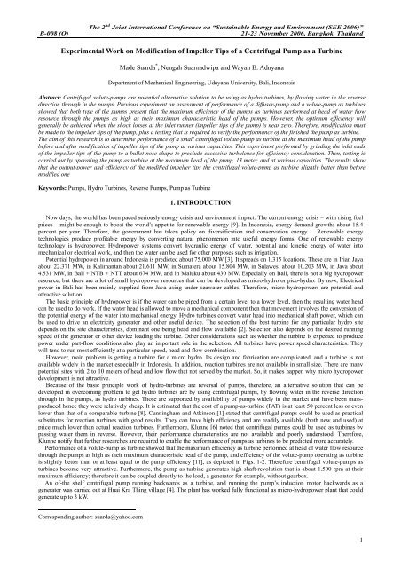
<str<strong>on</strong>g>Experimental</str<strong>on</strong>g> <str<strong>on</strong>g>Work</str<strong>on</strong>g> <strong>on</strong> Modificati<strong>on</strong> <strong>of</strong> <strong>Impeller</strong> <strong>Tips</strong> <strong>of</strong> a <strong>Centrifugal</strong> Pump as a Turbine<br />
Made Suarda * , Nengah Suarnadwipa and Wayan B. Adnyana<br />
Department <strong>of</strong> Mechanical Engineering, Udayana University, Bali, Ind<strong>on</strong>esia<br />
Abstract: <strong>Centrifugal</strong> volute-pumps are potential alternative soluti<strong>on</strong> to be using as hydro turbines, by flowing water in the reverse<br />
directi<strong>on</strong> through in the pumps. Previous experiment <strong>on</strong> assessment <strong>of</strong> performance <strong>of</strong> a diffuser-pump and a volute-pump as turbines<br />
showed that both type <strong>of</strong> the pumps present that the maximum efficiency <strong>of</strong> the pumps as turbines performed at head <strong>of</strong> water flow<br />
resource through the pumps as high as their maximum characteristic head <strong>of</strong> the pumps. However, the optimum efficiency will<br />
generally be achieved when the shock losses at the inlet runner (impeller tips <strong>of</strong> the pump) is near zero. Therefore, modificati<strong>on</strong> must<br />
be made to the impeller tips <strong>of</strong> the pump, plus a testing that is required to verify the performance <strong>of</strong> the finished the pump as turbine.<br />
The aim <strong>of</strong> this research is to determine performance <strong>of</strong> a small centrifugal volute-pump as turbine at the maximum head <strong>of</strong> the pump<br />
before and after modificati<strong>on</strong> <strong>of</strong> impeller tips <strong>of</strong> the pump at various capacities. This experiment performed by grinding the inlet ends<br />
<strong>of</strong> the impeller tips <strong>of</strong> the pump to a bullet-nose shape to preclude excessive turbulence for efficiency c<strong>on</strong>siderati<strong>on</strong>. Then, testing is<br />
carried out by operating the pump as turbine at the maximum head <strong>of</strong> the pump, 13 meter, and at various capacities. The results show<br />
that the output-power and efficiency <strong>of</strong> the modified impeller tips the centrifugal volute-pump as turbine slightly better than before<br />
modified <strong>on</strong>e<br />
Keywords: Pumps, Hydro Turbines, Reverse Pumps, Pump as Turbine<br />
1. INTRODUCTION<br />
Now days, the world has been paced seriously energy crisis and envir<strong>on</strong>ment impact. The current energy crisis – with rising fuel<br />
prices – might be enough to boost the world’s appetite for renewable energy [9]. In Ind<strong>on</strong>esia, energy demand growths about 15.4<br />
percent per year. Therefore, the government has taken policy <strong>on</strong> diversificati<strong>on</strong> and c<strong>on</strong>servati<strong>on</strong> energy. Renewable energy<br />
technologies produce pr<strong>of</strong>itable energy by c<strong>on</strong>verting natural phenomen<strong>on</strong> into useful energy forms. One <strong>of</strong> renewable energy<br />
technology is hydropower. Hydropower systems c<strong>on</strong>vert hydraulic energy <strong>of</strong> water, potential and kinetic energy <strong>of</strong> water into<br />
mechanical or electrical work, and then the water can be used for other purposes such as irrigati<strong>on</strong>.<br />
Potential hydropower in around Ind<strong>on</strong>esia is predicted about 75.000 MW [3]. It spreads <strong>on</strong> 1.315 locati<strong>on</strong>s. These are in Irian Jaya<br />
about 22.371 MW, in Kalimantan about 21.611 MW, in Sumatera about 15.804 MW, in Sulawesi about 10.203 MW, in Java about<br />
4.531 MW, in Bali + NTB + NTT about 674 MW, and in Maluku about 430 MW. Especially <strong>on</strong> Bali, there is not a big hydropower<br />
resource, but there are a lot <strong>of</strong> small hydropower resources that can be developed as micro-hydro or pico-hydro. By now, Electrical<br />
power in Bali has been mainly supplied from Java using under seawater cables. Therefore, micro hydropowers are potential and<br />
attractive soluti<strong>on</strong>.<br />
The basic principle <strong>of</strong> hydropower is if the water can be piped from a certain level to a lower level, then the resulting water head<br />
can be used to do work. If the water head is allowed to move a mechanical comp<strong>on</strong>ent then that movement involves the c<strong>on</strong>versi<strong>on</strong> <strong>of</strong><br />
the potential energy <strong>of</strong> the water into mechanical energy. Hydro turbines c<strong>on</strong>vert water head into mechanical shaft power, which can<br />
be used to drive an electricity generator and other useful device. The selecti<strong>on</strong> <strong>of</strong> the best turbine for any particular hydro site<br />
depends <strong>on</strong> the site characteristics, dominant <strong>on</strong>e being head and flow available [2]. Selecti<strong>on</strong> also depends <strong>on</strong> the desired running<br />
speed <strong>of</strong> the generator or other device loading the turbine. Other c<strong>on</strong>siderati<strong>on</strong>s such as whether the turbine is expected to produce<br />
power under part-flow c<strong>on</strong>diti<strong>on</strong>s also play an important role in the selecti<strong>on</strong>. All turbines have power speed characteristics. They<br />
will tend to run most efficiently at a particular speed, head and flow combinati<strong>on</strong>.<br />
However, main problem is getting a turbine for a micro hydro. Its design and fabricati<strong>on</strong> are complicated, and a turbine is not<br />
available widely in the market especially in Ind<strong>on</strong>esia. In additi<strong>on</strong>, reacti<strong>on</strong> turbines are not available in small size. There are many<br />
potential sites with 2 to 10 meters <strong>of</strong> head and low flow that not served by the market. So, it makes happen why micro hydropower<br />
development is not attractive.<br />
Because <strong>of</strong> the basic principle work <strong>of</strong> hydro-turbines are reversal <strong>of</strong> pumps, therefore, an alternative soluti<strong>on</strong> that can be<br />
developed in overcoming problem to get hydro turbines are by using centrifugal pumps, by flowing water in the reverse directi<strong>on</strong><br />
through in the pumps, as hydro turbines. Those are supported by availability <strong>of</strong> pumps widely in the market and have been massproduced<br />
hence they were relatively cheap. It is estimated that the cost <strong>of</strong> a pump-as-turbine (PAT) is at least 50 percent less or even<br />
lower than that <strong>of</strong> a comparable turbine [8]. Cunningham and Atkins<strong>on</strong> [1] stated that centrifugal pumps could be used as practical<br />
substitutes for reacti<strong>on</strong> turbines with good results. They can have high efficiency and are readily available (both new and used) at<br />
price much lower than actual reacti<strong>on</strong> turbines. Furthermore, Klunne [6] noted that centrifugal pumps could be used as turbines by<br />
passing water them in reverse. However, their performance characteristics are not available and poorly understood. Therefore,<br />
Klunne notify that further researches are required to enable the performance <strong>of</strong> pumps as turbines to be predicted more accurately.<br />
Performance <strong>of</strong> a volute-pump as turbine showed that the maximum efficiency as turbine performed at head <strong>of</strong> water flow resource<br />
through the pumps as high as their maximum characteristic head <strong>of</strong> the pump, and efficiency <strong>of</strong> the volute-pump operating as turbine<br />
is slightly better than or at least equal to the pump efficiency [11], as depicted in Figs. 1-2. Therefore centrifugal volute-pumps as<br />
turbines become very attractive. Furthermore, the pump as turbine generates high shaft-revoluti<strong>on</strong> that is about 1.500 rpm at their<br />
maximum efficiency; therefore it can be coupled directly to the load, a generator for example, without gearbox.<br />
An <strong>of</strong>-the shelf centrifugal pump running backwards as a turbine, and running the pump’s inducti<strong>on</strong> motor backwards as a<br />
generator was carried out at Huai Kra Thing village [4]. The plant has worked fully functi<strong>on</strong>al as micro-hydropower plant that could<br />
generate up to 3 kW.<br />
Corresp<strong>on</strong>ding author: suarda@yahoo.com<br />
1
The 2 nd Joint Internati<strong>on</strong>al C<strong>on</strong>ference <strong>on</strong> “Sustainable Energy and Envir<strong>on</strong>ment (SEE 2006)”<br />
B-008 (O) 21-23 November 2006, Bangkok, Thailand<br />
Performance <strong>of</strong> Volute Pump as Turbine vs Capacity<br />
40<br />
60<br />
35<br />
50<br />
30<br />
Efficiency (%)<br />
25<br />
20<br />
15<br />
10<br />
5<br />
0<br />
0.04 0.05 0.06 0.07 0.08 0.09<br />
40<br />
30<br />
20<br />
10<br />
0<br />
Output Power (Watt)<br />
Efficiency (%)<br />
35<br />
30<br />
25<br />
20<br />
15<br />
10<br />
5<br />
Efficiency <strong>of</strong> Volute Pump as Turbine vs Head<br />
Flow Capacity (m 3 /min)<br />
Efficiency<br />
Turbine Output Power (Watt)<br />
Fig. 1 Performance the volute pump as turbine<br />
at variati<strong>on</strong> <strong>of</strong> capacity<br />
0<br />
4.40 5.22 7.56 7.87 10.93 12.56<br />
Available Water Head (m)<br />
Fig. 2 Efficiency <strong>of</strong> the volute pump as turbine<br />
at variati<strong>on</strong> <strong>of</strong> the available head<br />
However, the optimum efficiency will generally be achieved when the shock losses at the inlet runner (pump<br />
impeller tips) is near zero [7]. Therefore, modificati<strong>on</strong> must be made to the impeller tips <strong>of</strong> the pump, plus a testing that<br />
is required to verify the performance <strong>of</strong> the finished the pump as turbine.<br />
Pump <strong>Impeller</strong> tip<br />
In-flow<br />
Pump vane<br />
<strong>Impeller</strong> peripheral<br />
<strong>Impeller</strong> tip Modificati<strong>on</strong><br />
Fig. 3 Rework <strong>on</strong> pump impeller tip for operati<strong>on</strong> as turbine<br />
2. METHODOLOGY<br />
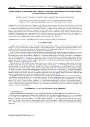
This experiment performed by grinding the inlet ends <strong>of</strong> the impeller tips <strong>of</strong> the pump to a bullet-nose shape to preclude excessive<br />
turbulence for efficiency c<strong>on</strong>siderati<strong>on</strong> as in Fig. 3. Then, testing is carried out by operating the pump as turbine at the maximum<br />
head <strong>of</strong> the pump, 13 meter, and at various capacities. Method <strong>of</strong> solving problem defined in problem formulati<strong>on</strong> is by experiment.<br />
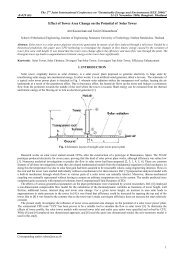
The first step <strong>of</strong> this experiment is to set all devices used as in Fig. 4. The next step is to vary capacity and head <strong>of</strong> water resource,<br />
and set for varying turbine load. Pumps that is used in this experiment is a centrifugal volute-type pump which have 0,13 m3/menit<br />
maximum capacity, 13 m maximum head, and 0.4 kW power <strong>of</strong> motor.<br />
2.1 Schematic <strong>of</strong> the experiment<br />
The wire <strong>of</strong> motor <strong>of</strong> the pump is removed then c<strong>on</strong>nected to torsi-meter and other equipments. Its arrangement is as in Fig. 4. In<br />
order to varying capacity <strong>of</strong> water supply is d<strong>on</strong>e by setting the degree open <strong>of</strong> valve (3). In order to varying load is d<strong>on</strong>e by setting<br />
the load <strong>on</strong> torque-meter.<br />
2.2 Procedure <strong>of</strong> the experiment<br />
1. Prepare the devices as in Fig. 4.<br />
2. Turn the valve and set <strong>on</strong> opened positi<strong>on</strong> that as water flow required.<br />
3. Set the load <strong>of</strong> torque-meter <strong>on</strong> run-way (without load).<br />
4. Record and tabulated the data such as flow Q; pressure p1, p2; scale reading <strong>on</strong> torque-meter m1, m2; and revoluti<strong>on</strong> <strong>of</strong><br />
turbine shaft, n.<br />
5. Repeat the steps 3 and 4 <strong>on</strong> variati<strong>on</strong> load <strong>of</strong> torque-meter up to full load (revoluti<strong>on</strong> is zero).<br />
2
The 2 nd Joint Internati<strong>on</strong>al C<strong>on</strong>ference <strong>on</strong> “Sustainable Energy and Envir<strong>on</strong>ment (SEE 2006)”<br />
B-008 (O) 21-23 November 2006, Bangkok, Thailand<br />
6. Repeat the steps 2 up to 5 <strong>on</strong> variati<strong>on</strong> <strong>of</strong> water flow capacity.<br />
7. Pull out the impeller <strong>of</strong> the pump, and modified the pump impeller tips.<br />
8. Repeat the steps 1 up to 7.<br />
The data that was recorded then manipulated as shown in Table 1.<br />
2<br />
1<br />
6<br />
5<br />
3<br />
7<br />
8<br />
H = 13 m<br />
1. Water supply tank<br />
2. Overflow<br />
3. Valve for regulating water flow capacity<br />
4. Pump as turbine<br />
5. Torque-meter<br />
6. Rpm-meter<br />
7. Pressure gauge, P1<br />
8. Pressure gauge, P2<br />
9. Draft tube<br />
10. V-notch weir<br />
11. Return water supply pump<br />
4<br />
9<br />
10<br />
11<br />
Fig. 4 Schematic <strong>of</strong> experiment <strong>of</strong> volute-type pump as turbine<br />
2.3 Theoretical water power<br />
Theoretical water power that is used to drive the turbine is<br />
P w = γ . Q.<br />
H (1)<br />
Where: P w = Theoretical water power (Watt); Q = Water flow capacity (m3/det); H = Head (m); and γ = Specific weight <strong>of</strong> water<br />
(N/m3)<br />
The head <strong>of</strong> water can be calculated by formula:<br />
v<br />
2<br />
p p<br />
v<br />
2<br />
( 2 − 1)<br />
( − )<br />
H = ( z − z ) + +<br />
2 1<br />
(2)<br />
2 1 γ 2g<br />
Where: z 1 , z 2 = lower and upper water elevati<strong>on</strong> to the turbine axis (m); p 1 , p 2 = input and output water static pressure (N/m 2 ); and v 1 ,<br />
v 2 = input and output water velocity (m/s)<br />
Velocity <strong>of</strong> water flow though in the turbine can be determined from flow capacity, which is measured using 90º v-notch weir<br />
[10]:<br />
2,50<br />
Q = 1,38.<br />
h<br />
(3)<br />
Where: Q = water flow capacity (m3/det); and h = water level at v-notch weir (m)<br />
2.4 Turbine performance<br />
The torque at shaft <strong>of</strong> pump as turbine is measured by using a manual pr<strong>on</strong>y-brake then can be calculated as follows [Keane &<br />
Phillips, 2003]:<br />
T = ( F1 − F2<br />
). R p = ( m1<br />
− m2<br />
).<br />
g.<br />
R<br />
p<br />
(4)<br />
where: F 1 , F 2 = the force <strong>on</strong> the belt <strong>of</strong> the pr<strong>on</strong>y brake (N); m 1 , m 2 = the scale reading <strong>on</strong> the pr<strong>on</strong>y brake (kg); g = accelerati<strong>on</strong> <strong>of</strong><br />
the gravity (m/det2); and R p = the pulley radius <strong>of</strong> the pr<strong>on</strong>y brake (m).<br />
Then, the power extracted from the pump as turbine is<br />
P t<br />
= T.ω (5)<br />
in which ω = 2πn/60 is the angular speed in rad/sec.<br />
Turbine efficiency is simply defined as<br />
Pt<br />
η<br />
t<br />
=<br />
(6)<br />
P<br />
w<br />
3
The 2 nd Joint Internati<strong>on</strong>al C<strong>on</strong>ference <strong>on</strong> “Sustainable Energy and Envir<strong>on</strong>ment (SEE 2006)”<br />
B-008 (O) 21-23 November 2006, Bangkok, Thailand<br />
3. RESULTS AND DISCUSSION<br />
3.1 Experiment Results<br />
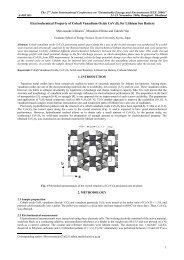
From the measurements and calculati<strong>on</strong> that have been d<strong>on</strong>e as presented in Table 1, then they are plotted in the graphs as in Figs.<br />
5. The graph shows that the power extracted from the turbine is increasing if the flow <strong>of</strong> water capacity is increased both <strong>on</strong> before<br />
and after modificati<strong>on</strong> <strong>of</strong> pump impeller tips. This is accordance with moment <strong>of</strong> momentum c<strong>on</strong>cept that turbine power proporti<strong>on</strong>al<br />
to mass flow rate. In additi<strong>on</strong>, the power and efficiency <strong>of</strong> the pump as turbine after modificati<strong>on</strong> is slightly higher than before<br />
modificati<strong>on</strong>. The maximum efficiency before modificati<strong>on</strong> is about 34.34% at water flow capacity about 0.002 m3/det which is<br />
close to the rated pump capacity at maximum efficiency i.e. 0.002 m3/det or 0.13 m3/det at head about 8 meter, as shown in Fig. 6. In<br />
the other hand, the maximum efficiency after modificati<strong>on</strong> is about 37.5% at lower water flow capacity, i.e. at 0.00149 m3/sec.<br />
Moreover, from Table 1 can be seen that the revoluti<strong>on</strong> <strong>of</strong> the pump as turbine high enough, that is about 1500 rpm at maximum<br />
efficiency therefore it can be directly coupled to a load such as a generator. Other interesting result <strong>of</strong> the pump as turbine is its<br />
efficiency is relatively stable <strong>on</strong> varying flow capacity from rated capacity up to maximum flow capacity. Therefore, it is could be<br />
operated at variati<strong>on</strong> load.<br />
Table 1 Performance <strong>of</strong> the pump as turbine before and after modificati<strong>on</strong><br />
Q H T (before) T (after) n (before) n (after) P t (before) P t (after) η t (before) η t (after)<br />
(m3/det) (m) (N.m) (N.m) (rpm) (rpm) (Watt) (Watt) (%) (%)<br />
0.00102 13.00 0.137 0.137 1,170 1,120 16.82 16.10 12.88 12.33<br />
0.00143 13.00 0.218 0.235 1,450 1,360 33.05 33.51 18.12 18.38<br />
0.00149 13.00 0.343 0.422 1,580 1,610 56.78 71.08 29.95 37.50<br />
0.00179 13.00 0.412 0.451 1,690 1,620 72.88 76.52 34.34 33.54<br />
0.00199 13.00 0.441 0.443 1,570 1,710 72.54 79.36 28.63 31.32<br />
Output-Power (Watt)<br />
90<br />
80<br />
70<br />
60<br />
50<br />
40<br />
30<br />
20<br />
10<br />
0<br />
90<br />
80<br />
70<br />
60<br />
50<br />
40<br />
30<br />
20<br />
10<br />
0<br />
0.0010 0.0014 0.0015 0.0018 0.0020<br />
Flow Capacity (m3/sec)<br />
Output-Power before modificati<strong>on</strong><br />
Efficiency before modificati<strong>on</strong><br />
Efficiency after modificati<strong>on</strong><br />
Output-Power after modificati<strong>on</strong><br />
Efficiency (%)<br />
Efficiency (%)<br />
30<br />
25<br />
20<br />
15<br />
10<br />
5<br />
Efficiency <strong>of</strong> Volute Pump, Model: CV-0512<br />
0<br />
0.00 0.02 0.04 0.06 0.08 0.10 0.12 0.13<br />
Flow Capacity (m 3 /min)<br />
13.0 11.8 10.9 9.7 8.0 5.8 1.9 0<br />
H ead <strong>of</strong> Pump (m)<br />
Fig. 5 Performance <strong>of</strong> the pump as turbine before and after modificati<strong>on</strong><br />
Fig. 6 Efficiency <strong>of</strong> the volute pump model CV-0512<br />
3.2 Discussi<strong>on</strong><br />
Performance <strong>of</strong> the volute pump as turbine after modificati<strong>on</strong> is <strong>of</strong>fers better efficiency than the before <strong>on</strong>e. Although this is<br />
changed just slightly in this experiment, where is the pump is very small but for the bigger pump as turbine will give higher effect.<br />
Although this efficiency <strong>of</strong> pump as turbine is still low enough, it is caused by its pump is very small and its efficiency is lower. From<br />
pump brochures can be seen that for the bigger pump it will <strong>of</strong>fer higher efficiency as well up to about 86%, therefore pumps as<br />
turbines are expected to present higher efficiency too. Moreover, this type <strong>of</strong> pump is widely available in the market from small to<br />
big size.<br />
Note that a pump is a turbine operated in reverse. This means that work is d<strong>on</strong>e to turn the impeller, which then imparts pressure<br />
to the fluid. The principles <strong>of</strong> operati<strong>on</strong> are identical. From the results can be summarized that in order to get the best performance <strong>of</strong><br />
a pump as turbine, it should be operated at its maximum pump head and at rated flow up to maximum flow capacity <strong>of</strong> the pump as is<br />
presented in its brochure. The volute-pump as turbine for bigger size <strong>of</strong> pump is recommended to be modified their impeller tips for<br />
better performance. However, for the smaller pumps, they were good enough directly operated as turbines because modificati<strong>on</strong> is<br />
just give slightly effect <strong>on</strong> their performance but they need hard work <strong>on</strong> modificati<strong>on</strong>.<br />
4
The 2 nd Joint Internati<strong>on</strong>al C<strong>on</strong>ference <strong>on</strong> “Sustainable Energy and Envir<strong>on</strong>ment (SEE 2006)”<br />
B-008 (O) 21-23 November 2006, Bangkok, Thailand<br />
4. CONCLUSION<br />
From the experiments and discussi<strong>on</strong>, the following c<strong>on</strong>clusi<strong>on</strong>s are obtained:<br />
1. Efficiency <strong>of</strong> the volute-pump operating as turbine after modificati<strong>on</strong> its impeller tips is slightly better than without modificati<strong>on</strong>.<br />
Furthermore, both pumps as turbines before and after modificati<strong>on</strong> generate high shaft-revoluti<strong>on</strong> that is about 1.500 rpm at their<br />
maximum efficiency; therefore it can be coupled directly to the load, a generator for example, without reducti<strong>on</strong> gear.<br />
2. The maximum efficiencies <strong>of</strong> the pump as turbine both <strong>on</strong> before and after modificati<strong>on</strong> are performed between the rated flow<br />
capacity <strong>of</strong> the pump at its maximum efficiency and the maximum flow capacity <strong>of</strong> the pump. In this flow range the efficiencies<br />
<strong>of</strong> the pump as turbine are relatively flatted <strong>on</strong> varying flow capacity, therefore, it is could be operated at variati<strong>on</strong> load.<br />
3. For bigger size <strong>of</strong> Volute-pumps as turbines are recommended to be modified their impeller tips for better performance.<br />
However, for the smaller pumps, they were good enough directly operated as turbines because modificati<strong>on</strong> is just give slightly<br />
effect <strong>on</strong> their performance but they need hard work <strong>on</strong> modificati<strong>on</strong>.<br />
5. ACKNOWLEDGMENTS<br />
The authors would like to express our gratitude to TPSDP project for providing financial support. Thanks are also extended to<br />
Mechanical Engineering Department – Udayana University, who provided me great assistances and supports.<br />
6. REFERENCES<br />
[1] Cunningham, P., and Atkins<strong>on</strong>, B. (1998) Micro Hydro Power in The Nineties, [Online, accessed: 7-4-2004], URL:<br />
http://www.elements.nb.ca/theme/energy/micro/micro.htm.<br />
[2] Evans, R.A. (2003) Waterpower, [Online, accessed: 12-4-2003], URL:http://www.evans.eu.com.<br />
[3] Departemen Energi dan Sumber Daya Mineral Republik Ind<strong>on</strong>esia (2004) Kebijakan Energi Nasi<strong>on</strong>al 2003 – 2020 : Kebijakan<br />
Energi yang Terpadu untuk Mendukung Pembangunan Nasi<strong>on</strong>al Berkelanjutan, Departemen Energi dan Sumber Daya Mineral,<br />
Jakarta<br />
[4] Greacen, C. (2006) Project Report – Huai Kra Thing Micro-hydro Project, 19 February 2006, [Online, accessed: 12-4-2003],<br />
URL: http://www.microhydro.com.<br />
[5] Keane and Phillips (2003) Characteristics <strong>of</strong> a Francis Reacti<strong>on</strong> Turbine, [Online, accessed: 26-6-2003], URL:<br />
http://www.microhydro.com.<br />
[6] Klunne, W. (2000) Micro Hydropower Basics, [Online, accessed: 12-4-2003], URL: http://www.microhydro.com.<br />
[7] Loban<strong>of</strong>f, V.S., Ross, R.R. (1996) <strong>Centrifugal</strong> Pumps: Design and Applicati<strong>on</strong>, Jaico Publishing House, Bombay, ch. 14.<br />
[8] Natural Resources Canada (2004) Micro-Hydropower Systems: A Buyer’s Guide, Her Majesty the Queen in Right <strong>of</strong> Canada.<br />
[9] Steindorf, S., dan Regan, T. (2001) New Turbine Can Extract Energy From Flowing Water, The Christian Science M<strong>on</strong>itor,<br />
[Online, accessed: 25-1-2004], URL:http://www.law.cornell.edu/ uscode/17/107.shtml.<br />
[10] Streeter, V.L., and Wylie, E.B. (1975) Fluid Mechanics, 6th editi<strong>on</strong>, McGraw-Hill Book Company, New York, ch. 8-9<br />
[11] Suarda, M. (2004) Assessment Of Performance Of A Diffuser-Pump And A Volute-Pump As Turbines, Proceeding <strong>of</strong> Research<br />
Grant Seminar <strong>of</strong> TPSDP Project, Surabaya.<br />
5