addendum #1 general specifications drawings - Oregon University ...
addendum #1 general specifications drawings - Oregon University ...
addendum #1 general specifications drawings - Oregon University ...

You also want an ePaper? Increase the reach of your titles
YUMPU automatically turns print PDFs into web optimized ePapers that Google loves.
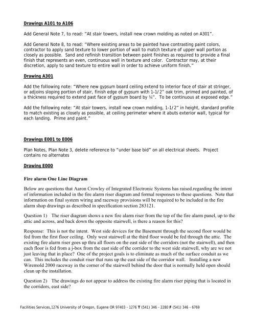
Drawings A101 to A106<br />
Add General Note 7, to read: “At stair towers, install new crown molding as noted on A301”.<br />
Add General Note 8, to read: “Where existing areas to be painted have contrasting paint colors,<br />
contractor to apply sand texture to lower portion of wall to match texture of upper wall portion as<br />
closely as possible. Sand and refinish transition between paint finishes as required to provide a final<br />
finish that represents an even, continuous wall in texture and color. Contractor may, at their<br />
discretion, apply to sand texture to entire wall in order to achieve uniform finish.”<br />
Drawing A301<br />
Add the following note: “Where new gypsum board ceiling extend to interior face of stair at stringer,<br />
or adjoins sloping portion of stair, finish edge of gypsum with 1-1/2” oak trim, primed and painted, of<br />
a thickness required to extend past face of gypsum board by ¼”. To be continuous at exposed edge.”<br />
Add the following note: “At stair towers, install new crown molding, 1-1/2” in height, standard profile<br />
to match existing as closely as possible, at ceiling perimeter where it abuts exterior wall, typical for<br />
each landing. Prime and paint.”<br />
Drawings E001 to E006<br />
Plan Notes, Plan Note 3, delete reference to “under base bid” on all electrical sheets. Project<br />
contains no alternates<br />
Drawing E000<br />
Fire alarm One Line Diagram<br />
Below are questions that Aaron Crowley of Integrated Electronic Systems has raised.regarding the intent<br />
of information included in the fire alarm riser diagram and formal responses to these questions. Note that<br />
information on final system wiring and raceway provisions will be required to be included in the fire<br />
alarm shop <strong>drawings</strong> as described in specification section 283121.<br />
Question 1) The riser diagram shows a new fire alarm riser from the top of the fire alarm panel, up to the<br />
attic and across, and back down the opposite stairwell, is there a reason for this<br />
Response: This is not the intent. West side devices for the Basement through the second floor would be<br />
fed from the first floor ceiling. Only west stairwell at the third floor would be fed through the attic. The<br />
existing fire alarm riser goes up thru all floors on the east side of the corridors (not the stairwell), and then<br />
each floor is fed from a j-box from the east side of the corridor to the west side stairwell, why are we not<br />
just leaving that in place One of the project goals is to eliminate as much of the surface conduit as we<br />
can. This includes the conduit riser that runs up the east side of the corridor wall. Installing a new<br />
Wiremold 2000 raceway in the corner of the stairwell behind the door that is normally held open should<br />
clean up the installation.<br />
Question 2) The <strong>drawings</strong> do not appear to address the existing fire alarm riser piping that is located in<br />
the corridors, east side<br />
Facilities Services,1276 <strong>University</strong> of <strong>Oregon</strong>, Eugene OR 97403 – 1276 T (541) 346 – 2280 F (541) 346 – 6769

![SOU Diversions Addendum _1[1]. - Oregon University System](https://img.yumpu.com/43178123/1/190x245/sou-diversions-addendum-11-oregon-university-system.jpg?quality=85)