Packaged Metering Manhole Specifications.pdf - Plasti-Fab, Inc.
Packaged Metering Manhole Specifications.pdf - Plasti-Fab, Inc.
Packaged Metering Manhole Specifications.pdf - Plasti-Fab, Inc.

Create successful ePaper yourself
Turn your PDF publications into a flip-book with our unique Google optimized e-Paper software.
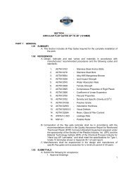
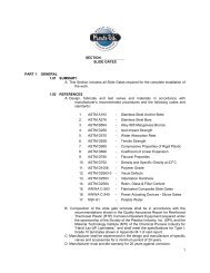
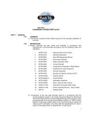
SECTION ____________<br />
PACKAGED METERING MANHOLE (PMM)<br />
PART 1<br />
GENERAL<br />
1.01 SUMMARY<br />
A. This Section includes all <strong>Packaged</strong> <strong>Metering</strong> <strong>Manhole</strong>s required for the<br />
complete installation of the work.<br />
1.02 REFERENCES<br />
A. Design, fabricate PMMs and materials in accordance with manufacturer’s<br />
recommended procedures and the following codes and standards:<br />
1. ASTM A193 - Stainless Steel Anchor Bolts<br />
2. ASTM D 256 - Izod Impact Strength<br />
3. ASTM D 570 - Water Absorption Rate<br />
4. ASTM D 638 - Tensile Strength<br />
5. ASTM D695 - Compressive Properties of Rigid <strong>Plasti</strong>c<br />
6. ASTM D 696 - Coefficient of Linear Expansion<br />
7. ASTM D 790 - Flexural Properties<br />
8. ASTM D792 - Density and Specific Gravity at 23 0 C<br />
9. ASTM D2563-0 - Visual Defects<br />
10. ASTM D 2583 - Indentation Hardness<br />
11. ASTM D2584 - Resin, Glass & Filler Content<br />
12. ASTM D3753-12 - Polyester <strong>Manhole</strong>s<br />
13. ISO1438/1-1980 - Open Channel Flow Measurement<br />
14. NSF-61 - Potable Water<br />
15. OSHA 1910.27 - Fixed Ladders<br />
B. Composition of the PMM laminate shall be in accordance with the<br />
recommendations shown in the Quality Assurance Report for Reinforced<br />
Thermoset <strong>Plasti</strong>c (RTP) Corrosion Resistant Equipment prepared under<br />
the sponsorship of the Society of the <strong>Plasti</strong>cs Industry, <strong>Inc</strong>. (SPI), and the<br />
Material Technology Institute (MTI) of the Chemical Process Industry for<br />
“Hand Lay-UP Laminates,” and shall meet the specifications for Type I,<br />
Grade 10 laminates shown in Appendix M-1 of said report.<br />
C. Manufacturer shall be experienced in the design and manufacture of specific<br />
PMMs and accessories for a minimum period of 20 years.<br />
D. Manufacturer must provide warranty for 25 years against corrosion.<br />
1
1.03 SUBMITTALS<br />
A. Submit the following for acceptance:<br />
1. Approval Drawings<br />
a. Showing all critical dimensions.<br />
b. Showing principal parts and materials.<br />
2. Spare parts list (when applicable).<br />
1.04 DELIVERY, STORAGE AND HANDLING<br />
A. Ship all PMMs with suitable packaging to protect products from damage.<br />
B. Protect PMM flanges, tabs and accessories from damage.<br />
C. The PMM shall be stored on a smooth flat surface, free of sharp objects, and<br />
if laid horizontally, shall be placed in such a way as to avoid structural<br />
damage.<br />
PART 2<br />
PRODUCTS<br />
2.01 MATERIALS<br />
A. PMM body shall be:<br />
1. Engineered composite fiberglass reinforced plastic (FRP).<br />
a. Molded in one piece to create a seamless corrosion barrier<br />
impervious to moisture.<br />
b. FRP resin shall be polyester / vinyl ester.<br />
2. PMM Hardware (when applicable): Type T-304L / T-316L / PREN __<br />
super duplex stainless steel.<br />
2.02 PMMS<br />
A. Acceptable Manufacturers:<br />
1. <strong>Plasti</strong>-<strong>Fab</strong> <strong>Inc</strong>.<br />
a. Shall be Model PMM________ (diameter x depth).<br />
2. The PMM fabrication, flume, engineering and customer support shall<br />
all be provided by the same company. Outsourcing any of these<br />
components is not acceptable.<br />
3. To assure quality control and single source accountability the same<br />
manufacturer shall fabricate and fully assemble the PMM and all<br />
components.<br />
4. Or approved equal. Pre-approved by Engineer at least 10 business<br />
days prior to bid date.<br />
a. Manufacturer must have a qualified Engineer on staff with at<br />
least 5 years experience with hydraulic measurement<br />
PMMs.<br />
2.03 DESIGN CRITERIA<br />
A. PMM shall conform to ASTM D3753-12.<br />
B. Composition of the PMM laminate shall be in accordance with the<br />
recommendations shown in the Quality Assurance Report for Reinforced<br />
Thermostat <strong>Plasti</strong>c (RTP) Corrosion Resistant Equipment prepared<br />
under the sponsorship the Society of the <strong>Plasti</strong>cs Industry, <strong>Inc</strong>. (SPI) and<br />
the Material Technology Institute of the Chemical Process Industries, <strong>Inc</strong>.<br />
(MTI) for “Hand Lay-up Laminates” and shall meet the specifications for<br />
Type 1, Grade 10 laminates shown in Appendix M-1 of said report.<br />
1. Visual inspection for defects shall be made without the aid of<br />
magnification and defects shall be classified as to type and level as<br />
shown in Table 1 of ANSI/ASTM D2563-0, approved 1977, (or any<br />
subsequent revision). Allowable surface tolerances are as follows:<br />
2
DEFECTS<br />
Cracks<br />
Crazing<br />
Blisters<br />
Chips<br />
Pits<br />
Dry Spots<br />
Fish Eyes<br />
Burned Areas<br />
Entrapped Air<br />
Wrinkles and solid blisters, not to<br />
exceed 1/8”<br />
Surface porosity (pinholes or pores<br />
in the laminate surface)<br />
Exposed Glass<br />
Exposure of cut edges<br />
Scratches<br />
Foreign Matter<br />
ALLOWABLE TOLERANCE<br />
None<br />
Maximum Deviation: 10% of<br />
thickness<br />
None<br />
None<br />
None more than .002” deep<br />
(.05mm)<br />
None<br />
C. Maximum Fiber Stress<br />
1. Ultimate or yield, whichever applies, does not exceed 2.5 times the<br />
working stress.<br />
2.04 CONSTRUCTION<br />
A. PMM<br />
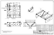
1. Each <strong>Packaged</strong> <strong>Metering</strong> <strong>Manhole</strong> shall be a complete integral unit<br />
consisting of: a corrosion resistant fiberglass reinforced plastic<br />
(FRP) manhole with sealed fiberglass bottom, fiberglass access<br />
ladder, metering flume and accessories as required.<br />
2. PMM body shall be totally manufactured of fiberglass reinforced<br />
polyester.<br />
3. Each PMM shall be molded individually to the exact dimensions<br />
specified.<br />
4. The thickness of the walls and floor of the PMM shall be not less than<br />
1/2" (12mm) thick.<br />
5. PMMs shall be manufactured of reinforced thermoset plastic in one<br />
integral piece that is structurally strong, lightweight, watertight and<br />
corrosion resistant to salt water, ground water, corrosive soil<br />
conditions and many commonly encountered industrial chemicals.<br />
6. PMM shall have UV Stabilizing pigment in the Resin to provide longterm<br />
protection from UV.<br />
7. PMM inside surface shall be smooth, isophthalic gelcoat of 10 - 20 mil<br />
(0.25 - 0.51mm) thickness. Exterior Surface shall be grey gel coat<br />
15-20 mil (0.25 – 0.51mm) thickness.<br />
8. The surface shall be free of exposed reinforcing fibers.<br />
9. The minimum glass content shall be 30% exclusive of gelcoat<br />
surfaces.<br />
10. Any portion of the flume or end adapters extending outside the<br />
manhole shall have a reinforced cover.<br />
3
11. The manhole sides, bottom and external flume sections shall be<br />
designed to withstand a static load of 150 lb/ft per foot (68<br />
kg/305mm) of depth with less than l/4" (6mm) deflection.<br />
12. There shall be no light duty angles of flanges protruding beyond the<br />
flume or manhole that can be damaged by shear or load forces.<br />
13. Inlet and Outlet Pipes: The FRP manhole and flume shall be provided<br />
with _____ inch / millimeter O.D. pipe stubs for connection to<br />
______ inch / millimeter O.D. incoming and outgoing (concrete /<br />
clay / fiberglass / cast iron / PVC) pipe. Flume end adapters shall<br />
allow a smooth flow transition from pipe flow to flume flow.<br />
a. Two neoprene boots with stainless steel clamping bands shall<br />
be supplied and sized to connect inlet and outlet pipe stubs<br />
to the pipeline.<br />
b. Pipe stubs shall have slip flanges for connection to existing line.<br />
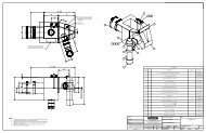
14. Cover<br />
a. The <strong>Packaged</strong> <strong>Metering</strong> <strong>Manhole</strong> will be furnished with a<br />
fiberglass cover equipped with heavy duty stainless steel<br />
hinges having l/2" (12mm) diameter hinge pins and<br />
stainless steel hasp for locking. The cover shall be<br />
sufficient strength to withstand 1000 lbs. (454kg) top load.<br />
The cover shall overlap the manhole and seat on a<br />
neoprene seal to prevent dirt, rain and debris from getting<br />
into the manhole.<br />
b. The <strong>Packaged</strong> <strong>Metering</strong> <strong>Manhole</strong> shall have a gastight<br />
aluminum lid for non-traffic loads mounted with a 20" / 24"<br />
(508mm / 610mm) concentric manway.<br />
c. The <strong>Packaged</strong> <strong>Metering</strong> <strong>Manhole</strong> shall have a concentric<br />
manway designed to withstand a 16,000 lb. (7257kg)<br />
vertical dynamic wheel load (H-20), plus lateral forces from<br />
earth loading, ground water and frozen soil. The manhole<br />
opening shall be a (4' (1219mm) diameter barrel use: 22-<br />
1/2" (572mm) I.D or 28" (711mm) I.D. - 5' (1524mm)<br />
diameter barrel use 22-1/2" (572mm) I.D., 28" (711mm) I.D.<br />
or 36" (914mm) I.D.) manway for use with a cast iron cover,<br />
suitable for H-20 highway loading.<br />
d. The <strong>Packaged</strong> <strong>Metering</strong> <strong>Manhole</strong> shall have aluminum hatch<br />
access ____ inch / millimeter x ____ inch / millimeter.<br />
15. Internal Ladder: The ladder rungs shall have a non-slip traction<br />
surface and internal stainless steel safety bar. The ladder shall<br />
meet or exceed OSHA General Industry Standards, Part 1910.27<br />
for "Fixed Ladders".<br />
16. Utility Tap: The manhole barrel shall be fitted with a 2" (51mm) FRP<br />
through-wall utility tap(s) having threaded connections to permit<br />
sub-grade entrance for power, sample or recording lines without<br />
damaging the watertight integrity of the manhole.<br />
17. A l/2” (12mm) thick expanded polystyrene bead board will be supplied<br />
for placement on the concrete slab under the manhole.<br />
4
18. The manhole shall be equipped with hold down brackets for anchoring<br />
the unit to a concrete slab.<br />
19. Options<br />
a. Instrument Shelf: Fiberglass shelf or bracket(s), as required,<br />
shall be furnished to allow installation of specific<br />
instrumentation described in (section / paragraph)<br />
_________ of the specification.<br />
b. Flume / Whole Bottom Cover: Fiberglass grating shall be<br />
installed over the flume to provide a walking surface and to<br />
prevent debris from falling into the flume.<br />
c. Head deflector / lid warning sign / ladder up with safety track.<br />
d. Vent piping / explosion proof fan.<br />
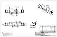
B. Flume<br />
1. Integral flume shall be <strong>Plasti</strong>-<strong>Fab</strong> model ____________<br />
2. Flume shall comply with Flume Specification in this Section.<br />
3. Nominal wall thickness shall be a minimum of l/4” (6mm) for areas<br />
inside the barrel and ½” (12mm) minimum for portions extending<br />
beyond the barrel.<br />
4. Flume extending beyond the manhole shall have a reinforced<br />
watertight fiberglass cover of sufficient strength to withstand soil<br />
loads up to 150 lb/ft per foot (68 kg/305mm) of depth when buried.<br />
2.05 PHYSICAL PROPERTIES<br />
A. Structural characteristics for a 1/8” (3mm) glass mat laminate shall meet the<br />
following minimum physical properties:<br />
Tensile strength<br />
Flexural Modulus<br />
Flexural Strength<br />
Compressive Strength<br />
Impact Strength<br />
Water absorption<br />
15,000 psi (1034 ksc)<br />
1,000,000 psi (70307 ksc)<br />
20,000 psi (1406 ksc)<br />
22,000 psi (1547 ksc)<br />
9.0 ft-lbs/in. (1.24 kgf/m)<br />
0.13% (in 24 hours)<br />
2.06 DIMENSIONS<br />
A. Fiberglass barrel shall be _____ 48” / 60” / 72” (1219mm / 1524mm /<br />
1829mm) diameter.<br />
B. <strong>Manhole</strong> shall be _____ feet / meters (invert to grade).<br />
5
PART 3<br />
EXECUTION<br />
3.01 INSTALLATION<br />
A. PMMS TOO LARGE TO SHIP FLATBED WILL BE SHIPPED IN FLANGED<br />
AND MATCH-DRILLED SECTIONS ALONG WITH STAINLESS STEEL<br />
FASTENERS FOR ONSITE ASSEMBLY.<br />
B. Verify that dimensions are correct and project conditions are suitable for<br />
installation. Do not proceed with installation until unsatisfactory<br />
conditions have been corrected.<br />
C. Thoroughly clean and remove all shipping materials prior to setting.<br />
D. Install products in accordance with engineer’s specifications, local codes,<br />
general comments below and the Manufacturer’s recommendations.<br />
E. Care shall be taken in the handling, storage and placement of the PMM in<br />
preparation for installation. The contractor shall become familiar with the<br />
recommended handling and installation procedures used with fiberglass<br />
<strong>Metering</strong> <strong>Manhole</strong>s to insure that the manhole is not damaged, and that<br />
the flume is installed in a manner that is consistent with obtaining good<br />
Open Channel flow results.<br />
F. Slinging will be accomplished using nylon or other fabric material. Under no<br />
circumstances shall cable or chain slings be used in direct contact with<br />
fiberglass surfaces<br />
G. The PMM shall be installed level end-to-end and side-to-side, and must<br />
remain level throughout installation. The flume is factory installed in the<br />
<strong>Metering</strong> <strong>Manhole</strong> so that it is absolutely level from front to back and<br />
from side to side, and must remain level after installation.<br />
H. The site shall be excavated wide enough to accommodate the manhole and<br />
to provide a safe working environment for workers.<br />
I. The contractor shall provide a level concrete slab with a smooth troweled<br />
surface. Pad elevation shall be as shown on the drawings, and<br />
positioned so that the invert of manhole piping matches that of the<br />
pipeline. Prior to manhole placement the slab shall be cleaned of all<br />
sharp objects and debris.<br />
J. The foam pad supplied with the manhole shall be placed in the proper<br />
position.<br />
K. If the pipe is already in place the neoprene boots and s/s bands shall be<br />
slipped onto the pipe ends before lowering manhole onto concrete slab.<br />
The neoprene boots can be slipped over pipe ends and the stainless<br />
steel clamps tightened securely. Under no circumstances shall<br />
petroleum lubricants of any type be used to install neoprene boots.<br />
L. <strong>Packaged</strong> <strong>Metering</strong> <strong>Manhole</strong> shall be lowered onto pad in accordance with<br />
the manufacturer's written recommendations.<br />
M. Flume level shall be checked and PMM adjusted if necessary.<br />
N. After the level is confirmed all anchor bolts shall be securely tightened.<br />
O. On larger flumes all open spaces under the flume shall be filled with grout to<br />
provide adequate structural support.<br />
P. Backfill<br />
1. Care shall be taken to avoid uneven backfill loads on the FRP<br />
manhole and flume.<br />
2. Groundwater or surface water runoff shall not be allowed to<br />
accumulate in the open excavation around a manhole that has not<br />
been completely backfilled.<br />
3. Backfill materials shall be placed evenly around the packaged<br />
manhole in approximately 12” (305mm) lifts.<br />
6
4. If materials other than pea gravel or sand are to be used as fill there<br />
shall be no soil lumps or sharp objects such as rocks or concrete,<br />
or other debris larger than 1” (25mm) in size.<br />
5. All fill work will be in compliance with local codes, and shall meet the<br />
inspection standards established by the engineer.<br />
6. Stable Soils: Bearing capacity greater than 2000 lbs/ft 2 (186 kg/m 2 ).<br />
Native soil, 1/4" x 3/8" (6mm x 9.5mm) round aggregate gravel or<br />
sand shall be used as backfill material, and placed in accordance<br />
with the above specifications.<br />
7. Unstable Soils and High Water Tables: Bearing capacity less than<br />
2000/lbs/ft 2 (186 kg/m 2 ). Sand or 1/4" x 3/8" (6mm x 9.5mm)<br />
rounded aggregate, compacted, shall be used in unstable soils<br />
such as expansive clays, marsh and/or where the water table may<br />
be less than 5’ (1524mm). from finished grade. Selected backfill<br />
shall be placed in maximum 12” (305mm) lifts, a minimum of 24”<br />
(610mm) surrounding the manhole, and compacted to 85%<br />
Standard Proctor Density.<br />
8. Finish to Grade: For concentric top, contractor shall finish to grade<br />
using brick and mortar or precast concrete rings to construct<br />
chimney of required height. Mortar bed and first grade ring shall<br />
be firmly supported on flat, bearing shoulder of the packaged<br />
manhole.<br />
3.02 ADJUSTMENT AND START UP<br />
A. Check Flume for being level both directons and PMM for meeting<br />
dimensional requirements and cleaned per manufacture’s instructions.<br />
B. Start up / calibration of meter per section __________ (when applicable).<br />
C. Site to be left clean and free of any debris.<br />
D. Representative shall complete a Certification of Proper Installation and<br />
provide copies to the Owner, Engineer, Contractor and Manufacturing<br />
Facility. (When applicable)<br />
3.03 FIELD TESTING (OPTIONAL)<br />
A. Qualified Factory representative shall provide (8) hours of training for facility<br />
employees. (Optional)<br />
B. Representative shall complete a Certification of Proper Installation and<br />
provide copies to the Owner, Engineer, Contractor and Manufacturing<br />
Facility. (When applicable)<br />
END OF SECTION<br />
7