M20R 3810 Rev A page.. - Delta Aviation LLC
M20R 3810 Rev A page.. - Delta Aviation LLC
M20R 3810 Rev A page.. - Delta Aviation LLC

Create successful ePaper yourself
Turn your PDF publications into a flip-book with our unique Google optimized e-Paper software.
MOONEY<br />
<strong>M20R</strong> - OVATION 2 GX<br />
SECTION VII<br />
AIRPLANE AND SYSTEM DESCRIPTION<br />
IGNITION SYSTEM<br />
Power from the engine crankshaft is transmitted through camshaft gear to the magneto drive<br />
gears, which in turn drives the magneto drive couplings. The left magneto incorporates an impulse<br />
coupling. As the rubber bushings in the drive gear turns the coupling drive lugs, counterweighted<br />
latch pawls inside the coupling cover, engage pins on the magneto case and hold back<br />
the latch plate until forced inward by the coupling cover. When the latch plate is released, the<br />
coupling spring spins the magneto shaft through its neutral position and the breaker opens to<br />
produce a high voltage surge in the secondary coil. The spring action permits the latch plate,<br />
magnet and breaker to be delayed through a lag angle of 30 degrees of drive gear rotation during<br />
the engine cranking period. Two lobes on the breaker cam produce two sparks per revolution of<br />
the drive shaft. After engine is running, counter--weights hold the latch pawls away from the stop<br />
pins and the magneto shaft is driven at full advance.<br />
The engine firing order is 1--6--3--2--5--4. Ignition harnesses are connected to the magnetos so<br />
right magneto fires the upper plugs on the right side and lower plugs on the left. The left magneto<br />
fires the upper plugs on the left and lower plugs on the right. The magneto cases, spark plugs,<br />
harnesses and connections are shielded to prevent radio interference.<br />
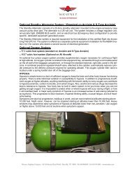
FILTER<br />
NACA AIR INLET<br />
FILTER CAN<br />
FUEL<br />
CONTROL<br />
UNIT<br />
ALT.<br />
AIR<br />
BOX<br />
ENGINE INDUCTION<br />
AIR SYSTEM<br />
FIGURE 7 -6 AIR INDUCTION SYSTEM SCHEMATIC<br />
AIR INDUCTION SYSTEM<br />
The engine air induction system consists of a NACA, flush--type air inlet duct located on front of<br />
lower cowling. The air inlet duct incorporates the air filter housing. This housing contains a<br />
throw--away, paper canister type air filter element. The optional air filter is cleanable and must be<br />
serviced at 100 hour intervals. Refer the maintenance manual for instructions.<br />
A secondary or alternate air source for combustion air is provided. This air inlet has a spring<br />
loaded door which normally remains closed. If the air filter or induction air inlet should become<br />
ORIGINAL ISSUE - 12-11-07<br />
<strong>Rev</strong>ision A -- 08-03-2010<br />
AIRPLANE FLIGHT MANUAL<br />
7--21