Model DNV-33D - Teledyne Hastings Instruments
Model DNV-33D - Teledyne Hastings Instruments
Model DNV-33D - Teledyne Hastings Instruments

Create successful ePaper yourself
Turn your PDF publications into a flip-book with our unique Google optimized e-Paper software.
TELEDYNE HASTINGS<br />
INSTRUCTION<br />
INSTRUCTION MANUAL<br />
INSTRUMENTS<br />
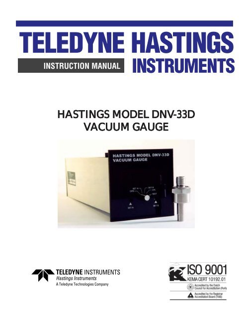
HASTINGS MODEL <strong>DNV</strong>-<strong>33D</strong><br />
VACUUM GAUGE<br />
page 1
Manual Print History<br />
The print history shown below lists the printing dates of all revisions and addenda created for<br />
this manual. The revision level letter increases alphabetically as the manual undergoes subsequent<br />
updates. Addenda, which are released between revisions, contain important change<br />
information that the user should incorporate immediately into the manual. Addenda are numbered<br />
sequentially. When a new revision is created, all addenda associated with the previous<br />
revision of the manual are incorporated into the new revision of the manual. Each new revision<br />
includes a revised copy of this print history page.<br />
Revision A (Document Number 156-122000) .................................................... December 2000<br />
Revision B (Document Number 156-082005) ..........................................................August 2005<br />
Visit www.teledyne-hi.com for WEEE disposal guidance.<br />
page 2<br />
<strong>Hastings</strong> <strong>Instruments</strong> reserves the right to change or modify the design of its equipment without<br />
any obligation to provide notification of change or intent to change.
Table of Contents<br />
I<br />
II<br />
GENERAL DESCRIPTION ..................................................................... 5<br />
OPERATION PRINCIPLE ....................................................................... 7<br />
1.0 SPECIFICATIONS<br />
................................................................................... 7<br />
2.0 INSTALLA<br />
ALLATION PROCEDURE<br />
............................................................. 8<br />
2.1 Panel Mounting .................................................................................................................. 8<br />
2.2 Gauge Tube Connections ................................................................................................... 8<br />
2.3 Connection of Relay Contacts and Output Terminals ....................................................... 8<br />
2.4 Gauge Tube Installation ..................................................................................................... 8<br />
3.0 OPERATION OF VACUUM GAUGE<br />
UGE......................................................<br />
9<br />
3.1 Powering of Vacuum Gauge ............................................................................................... 9<br />
3.2 Switch Position ................................................................................................................... 9<br />
4.0 CALIBRATION<br />
AND TROUBLESHOO<br />
OUBLESHOOTING GUIDE 9<br />
4.1 Check of Tube Accuracy .................................................................................................... 9<br />
4.2 <strong>DNV</strong>-33 Calibration ........................................................................................................ 10<br />
4.2.1 Reference Check .............................................................................................................. 10<br />
4.2.2 Recalibration for Length Gauge Tube Cable.................................................................... 10<br />
4.2.3 Optimizing Gauge Tube Accuracy ................................................................................... 10<br />
5.0 NOTES ON VACUUM MEASUREMENT ........................................... 10<br />
5.1 Effects of Condensable Vapors ......................................................................................... 10<br />
5.2 Outgassing........................................................................................................................ 11<br />
5.3 Ingassing .......................................................................................................................... 11<br />
5.4 Effect of Thermal Conductivity ...................................................................................... 11<br />
5.5 Effect of System Conductance ......................................................................................... 15<br />
6.0 WARRANTY<br />
........................................................................................... 12<br />
page 3
page 4
SECTION I<br />
General Description<br />
The <strong>Hastings</strong> Digital Vacuum Gauge, <strong>Model</strong> <strong>DNV</strong>-<strong>33D</strong>, incorporates proven <strong>Hastings</strong> thermopile<br />
technology to produce a linear vacuum gauge that covers the range of 1-1000 mTorr. The<br />
digital display reads directly in mTorr. The instrument provides an analog output signal which<br />
may be used to drive a remote indicator for recording, data logging, etc. The output is scale is<br />
1 volt for 1000 mTorr.<br />
The <strong>DNV</strong>-<strong>33D</strong> also includes dual set points (A set and B set) with LED indicators located on<br />
the front panel. Relay contacts are also provided for remote switching.<br />
The rear panel of the instrument provides access to terminal blocks for AC power cord, gauge<br />
tube, relays and analog output connections. The calibration adjustment potentiometers may also<br />
be accessed through the back panelof the unit. The instrument is factory calibrated on a standard<br />
average curve for <strong>DNV</strong>-33 vacuum gauges.<br />
page 5
page 6
SECTION II<br />
Operating Principle<br />
The operation of <strong>Hastings</strong> vacuum gauges uses a patented noble metal thermopile circuit. The<br />
hot junctions of the thermopile are heated directly by an AC current while an equal number of<br />
cold junctions are kept at ambient temperature by heavy mounting studs. Thus a DC voltage is<br />
then generated between the hot and cold junctions. As the pressure decreases, the lowering of<br />
the thermal conductivity of the gas surrounding the hot junction tends to increase the temperature<br />
of the hot junctions, thus increasing the output of the thermopile. This change in output is<br />
then amplified, linearized, and calibrated as a function of pressure.<br />
1.0 SPECIFICATIONS<br />
Indicator <strong>Model</strong> ....................................................................................................<strong>DNV</strong>-<strong>33D</strong><br />
Case Dimension ....................................................... Front Panel 96mm SQ. Depth 10 ¾”<br />
Gauge Tube Type ....................................................... DV-<strong>33D</strong>-1, DV-<strong>33D</strong>-2, DV-<strong>33D</strong>-3*<br />
Gauge Tube Shell ......................................................................Welded stainless steel shell<br />
Overpressure .............................................................................................1500 PSIG max.<br />
Panel Cut-out ................................................ 3-1/16” (77.5 mm) H x 3-5/8” (92mm)W<br />
Range .............................................................................................................. 1-1000 mTorr<br />
Readout ........................................................................................................... Digital Meter<br />
Power ....................................................................................... 115 VAC, less than 6 watts<br />
Outputs ................................................................. Linear 0-1 VDC analog @ 4 ma. Max.<br />
Calibration .............................................................................. Calibrated for air or nitrogen<br />
*Dash number Defines System Fitting Differences:<br />
-1 Weld Fitting<br />
-2 Cajon #SS-4 VCR Male Gland<br />
-3 Cajon #SS-4 VCR Female Gland<br />
page 7
2.0 INSTALLATION<br />
QUICK START<br />
Install DV-<strong>33D</strong> gauge tube in vacuum system (see section 2.4). Ensure system<br />
is leak free.<br />
Connect the tube to the <strong>DNV</strong>-<strong>33D</strong> power supply/display and apply 115 VAC.<br />
Allow 30 minutes for warm-up (see section 3.1).<br />
Set the switch on the <strong>DNV</strong>-<strong>33D</strong> to the “OPR” position for normal operation<br />
(factory calibration).<br />
Set the switch on the <strong>DNV</strong>-<strong>33D</strong> to the “Set A” position. The relay will now be<br />
energized when the pressure is less than the set point. The set point LED will be<br />
on when the relay is energized. The set point may be set by adjusting the appropriate<br />
potentiometer on the front panel.<br />
Set the switch on the <strong>DNV</strong>-<strong>33D</strong> to the “Set B” position. The relay will now be<br />
energized when the pressure is less than the set point. The set point LED will be<br />
on when the relay is energized. The set point may be set by adjusting the appropriate<br />
potentiometer on the front panel.<br />
Set the switch on the <strong>DNV</strong>-<strong>33D</strong> to the “CAL” position. This is to be used when<br />
zeroing the gauge with the tube at a pressure less than 0.1 mTorr.<br />
Set the switch on the <strong>DNV</strong>-<strong>33D</strong> to the “TEST” position. Use this position to<br />
check the <strong>DNV</strong>-<strong>33D</strong> and to set the gain for individual tubes.<br />
2.1 Panel Mounting<br />
The <strong>DNV</strong>-<strong>33D</strong> instrument package can be mounted in a 3-1/16 inch high by 3-5/8 inches wide<br />
hole. Secure the gauge with the mounting brackets provided.<br />
2.2 Connect the Gauge Tube wire to the gauge as follows:<br />
REAR PANEL GAUGE TUBE WIRE COLOR<br />
“TUBE” PIN #<br />
A A BLACK<br />
C C WHITE<br />
D D GREEN<br />
2.3 Connect other wires to relay contacts and output terminals<br />
minals.<br />
page 8<br />
2.4 Gauge Tube Installation<br />
tion<br />
Install the gauge tube in a clean, dry vacuum system with the open end pointing down so as to<br />
be self-draining should any vapors condense within the tube (See Sec. 5.1). For maximum<br />
accuracy, it is recommended that the tube be outgassed in the vacuum system for a minimum of<br />
4 hours.
3.0 OPERATION OF VACUUM GAUGE<br />
3.1 Power<br />
ering ing of Vacuum Gauge<br />
Plug the 8 ft. power cable into a single phase 115 VAC (<strong>DNV</strong>-<strong>33D</strong>) or 230 VAC (ENDV-<br />
<strong>33D</strong>)line. A line frequency of either 50 or 60 Hz is satisfactory. Allow 30-40 minutes for warmup.<br />
Plug the gauge tube cable onto the gauge tube. When the tube is exposed to a pressure greater<br />
than1000 mTorr, the analog output will be over 2 volts, and the display will read “1”.<br />
The relay will energize when the pressure is below the trip points. “Normal” relay position is deenergized<br />
(ATM pressure side of set point.)<br />
3.2 Switch Position<br />
“OPR” Normal operating position. Display reads pressure. Output on back panel reads 0-1<br />
volt.<br />
“SET A; SET B” Displays the trip point of the appropriate relay. If the pressure is below the trip<br />
point the relay is energized and the LED will be lit. The trip points can be set from 0-950 mTorr.<br />
The relay trip points are set by adjusting the appropriate pot located on the front panel.<br />
“CAL” Used when zeroing the vacuum gauge tube at hard vacuum. Adjust the Cal pot on the<br />
rear panel for 000 on the display.<br />
“Test” A voltage is injected into the 2 nd stage AMP so that the GAIN of the gauge can be set on<br />
the average curve. Adjust ‘GAIN’ pot on rear panel for “400” on the display. NOTE: The<br />
signal output will change when the switch is put in this position and the set points may trip. See<br />
section 4.2.1 Reference Check.<br />
4.0 CALIBRATION AND TROUBLESHOOTING GUIDE<br />
All <strong>Hastings</strong> vacuum gauges and tubes have been carefully checked and calibrated at the factory<br />
before shipment. If a calibration check is desired the methods in the following sections may<br />
prove helpful.<br />
4.1 Check of Tube<br />
Accuracy<br />
The simplest and quickest method of checking the operation and calibration of power supply/<br />
display and gauge tube is to keep a new, clean gauge tube on hand as a “standard”. To check<br />
operation, install both of the gauge tubes together in the same clean, dry vacuum system, and<br />
pump until a steady pressure is obtained. Plug the gauge onto both tubes alternately and check<br />
reading. Be sure to allow time for readings to settle. If the tube reads a considerably higher<br />
pressure than the tube being used as a standard, a calibration shift in the old tube has occured.<br />
This is most likely resulting from tube contamination. The tube calibration can possibley be<br />
restored by gently rinsing the interior of the tube with a solvent such as trichlorethylene. After<br />
cleaning, thoroughly dry the tube and degas it before reinstallation into a vacuum system. This<br />
is done to avoid system contamination by the solvent. If calibration cannot be restored by this<br />
precedure, replace the old tube with a new gauge tube.<br />
CAUTION: Do not attempt to measure the resistance of the gauge tube element while it is<br />
under vacuum. Some ohmmeters apply measuring voltages sufficient to burn out the thermopile<br />
while under vacuum. The resistance of the gauge tube can be measured safely at atmospheric<br />
pressure. This measurement is made between pins 3, 5 and 7 counting clockwise from<br />
the key looking at the base of the gauge tube. A measuring device such as the Triple <strong>Model</strong> 630<br />
Test Set with ohms switch on the “X10” range, is suitable for this purpose.<br />
page 9
4.2 <strong>DNV</strong>-33 -33 Calibration<br />
Warranty and Repair<br />
All calibration voltages are factory set and will rarely change. The methods for checking gauge<br />
calibration are detailed below:<br />
4.2.1 Reference Check<br />
The <strong>DNV</strong>-<strong>33D</strong> incorporates a quick reference check reading. To utilize this feature the front<br />
panel switch must be in the TEST position. In this position the digital display should read “400”<br />
(+3). If it does not read this the calibration GAIN pot should be adjusted to bring the reading<br />
back to “400”. This will bring the gauge back on the standard average calibration curve.<br />
NOTE: The signal output will change when the switch is put in this position and the set points<br />
may trip.<br />
Pump the gauge tube down to hard vacuum. Set the front panel switch to the ‘CAL’ position.<br />
Adjust the ‘CAL’ pot in the rear of the unit for 000 on the display. If there is a midscale reference<br />
available to the system, see section 4.2.3 on recalibration. Calibration is complete for use<br />
with the standard average curve.<br />
4.2.2 Recalibration for Different Length Gauge Tube Cables<br />
A maximum of 100 feet of gauge tube cable can be utilized by the <strong>DNV</strong>-<strong>33D</strong>. If the cable length<br />
or size (18 gauge) is changed, the unit must be recalibrated. The procedure for recalibration is<br />
described in section 4.2.1.<br />
4.2.3 Optimizing Gauge Tube<br />
Accuracy<br />
Individual tubes can be trimmed for best fit upscale on the curve by performing a calibration<br />
adjustment of the gain pot vs. tube output against an accurate reference standard, to do this:<br />
Pump the gauge tube down to hard vacuum. Set the front panel switch to the “CAL” position.<br />
Adjust the “CAL” potentiometer in the rear of the unit until the display reads 000.<br />
Pump the system to a known pressure using a reference in the system. At this pressure, adjust<br />
the gain potentiometer until the display reading matches the reference reading. The unit should<br />
now be calibrated. Best average fit to the curve will occur if 700 mTorr is used for this setting.<br />
Do not use this instrument with another tube unless resetting the gain to “400” per 4.2.1 or<br />
performing the above procedure for the specific tube.<br />
5.0 Notes on Vacuum Measurements<br />
5.1 Effects of Condensable Vapor<br />
apors<br />
If the readings of <strong>Hastings</strong> gauges are to be compared with readings of other types of gauges,<br />
consideration must be given to the possible effects of condensable vapors on other gauges. For<br />
example, none of the many types of McLeod gauges, give correct readings if condensable<br />
vapors such as water, alcohol, acetone, etc., are present in the gauge. The McLeod gauge<br />
operates by compressing residual gases and vapors to obtain a reading, and this compression will<br />
tend to compress vapors that are present. This usally results in pressure reading that is lower<br />
than the actual pressure. Furthermore two different McLeod gauges could be used and both<br />
may have different readings. Both of these readings however could be incorrect if vapors are<br />
page 10
present. <strong>Hastings</strong> thermopile gauges however, have the useful property of responding to the<br />
total pressure of all gases and vapors that are present in the gauge tube.<br />
To exclude vapors from a vacuum system, it is necessary to employ a trap of some kind that will<br />
absorb or condense vapors. Water vapor is by far the most common source of this difficulty. A<br />
cold trap cooled by liquid nitrogen is an effective means in removing vapors.<br />
It may be necessary to keep McLeod gauges constently under vacuum for several hours, or days<br />
with a trap before it will read correctly. The use of rubber or Tygon tubing connecting the gauge<br />
to the vacuum system can lead to gross errors due to excessive outgassing and or adsorbtion by<br />
the tube. It is recommended that only glass or metal tubing be used. Reference should be made<br />
to the instructions furnished by the manufacturer of the McLeod gauge to be sure that it is<br />
provided with a suitable trap.<br />
5.2 Outgassing<br />
<strong>Hastings</strong> gauge tubes are fabricated from materials which have been proven by years of usage to<br />
be relatively free from outgassing. However; all surfaces of glass and metal that are exposed to<br />
the vacuum system may liberate gases and vapors that were previously adsorbed during exposure<br />
to the atmosphere. If the surfaces are contaminated with foreign matter, this outgassing<br />
may be much more persistent than if the surfaces are clean. The possibility of outgassing must<br />
be considered in checking the accuracy of <strong>Hastings</strong> gauges or in checking for leaks. This is<br />
especially important when working with pressures of less than 10 mTorr where atmospheric<br />
gases are likely to flood the enclosure due to leaks.<br />
Also, if the system is being pumped continuously, gauges spaced at different distances from the<br />
pump will register different pressures. For a reliable comparison of different vacuum gauges, it<br />
is necessary then to insure that the vacuum system be free of any outgasses or other sources of<br />
apparent leaks. This can best be determined by closing off the system from the pumps and<br />
observing if there is any rise in pressure within the range of interest.<br />
5.3 Ingassing<br />
Ingassing is an effect opposite to outgassing and may also lead to erroneous readings. Ionization<br />
gauges exhibit a kind of pumping action that tends to clean up residual gasses in certain ranges<br />
of pressure and thereby lower the pressure. Also, if a cold trap is in a closed system, the total<br />
pressure may change considerable while condenseble vapors such as water, carbon dioxide and<br />
mercury and being condensed.<br />
5.4 Effects of Thermal Conductivity<br />
All <strong>Hastings</strong> vacuum gauges are originally calibrated in dry air. Since this calibration is a<br />
function of thermal conductivity, any gas having a thermal conductivity different from that of air<br />
will also have a different calibration. Contact factory for calibration in gases other than air.<br />
5.5 Effects of System Conductance<br />
Each element that makes up a vacuum system has associated with it a certain conductance (that<br />
is the opposite of resistance). For example, baffles, connecting tubing, and sharp turns may<br />
cause pressure drops throughout the system during pumping and during the time in which the<br />
system is reaching static equilibrium. It is not an uncommen occurence to measure different<br />
pressures at different locations in a vacuum system. In checking the calibration of a vacuum<br />
gauge, care must be taken to insure that the gauge and the reference are at the same pressure.<br />
page 11
SECTION 6<br />
Warranty<br />
6.1 Warranty Repair Policy<br />
<strong>Hastings</strong> <strong>Instruments</strong> warrants this product for a period of one year from the date of shipment to be free<br />
from defects in material and workmanship. This warranty does not apply to defects or failures resulting<br />
from unauthorized modification, misuse or mishandling of the product. This warranty does not apply to<br />
batteries or other expendable parts, nor to damage caused by leaking batteries or any similar occurrence.<br />
This warranty does not apply to any instrument which has had a tamper seal removed or broken.<br />
This warranty is in lieu of all other warranties, expressed or implied, including any implied warranty as to<br />
fitness for a particular use. <strong>Hastings</strong> <strong>Instruments</strong> shall not be liable for any indirect or consequential<br />
damages.<br />
<strong>Hastings</strong> <strong>Instruments</strong>, will, at its option, repair, replace or refund the selling price of the product if<br />
<strong>Hastings</strong> <strong>Instruments</strong> determines, in good faith, that it is defective in materials or workmanship during the<br />
warranty period. Defective instruments should be returned to <strong>Hastings</strong> <strong>Instruments</strong>, shipment prepaid,<br />
together with a written statement of the problem and a Return Material Authorization (RMA) number.<br />
Please consult the factory for your RMA number before returning any product for repair. Collect freight<br />
will not be accepted.<br />
.2 Non-Warranty Repair Policy<br />
Any product returned for a non-warranty repair must be accompanied by a purchase order, RMA form<br />
and a written description of the problem with the instrument. If the repair cost is higher, you will be<br />
contacted for authorization before we proceed with any repairs. If you then choose not to have the<br />
product repaired, a minimum will be charged to cover the processing and inspection. Please consult the<br />
factory for your RMA number before returning any product repair.<br />
TELEDYNE HASTINGS INSTRUMENTS<br />
804 NEWCOMBE AVENUE<br />
HAMPTON, VIRGINIA 23669 U.S.A.<br />
ATTENTION: REPAIR DEPARTMENT<br />
TELEPHONE (757) 723-6531<br />
1-800-950-2468<br />
FAX (757) 723-3925<br />
E MAIL<br />
hastings_instruments@teledyne.com<br />
INTERNET ADDRESS http://www.teledyne-hi.com/<br />
Repair Forms may be obtained from the “Information Request” section of the<br />
<strong>Hastings</strong> <strong>Instruments</strong> web site.<br />
page 12