HFM-401/405 - Teledyne Hastings Instruments
HFM-401/405 - Teledyne Hastings Instruments
HFM-401/405 - Teledyne Hastings Instruments
Create successful ePaper yourself
Turn your PDF publications into a flip-book with our unique Google optimized e-Paper software.
<strong>401</strong>-<strong>405</strong> SERIES - iv -
<strong>401</strong>-<strong>405</strong> SERIES - v -
CAUTIONThis instrument is available with multiple pin-outs.Ensure electrical connections are correct.CAUTIONThe 400-I series flow meters are designed for IECInstallation/Over voltage Category II – single phase receptacleconnected loads.NOTEThe <strong>Hastings</strong> 400 Series flow meters are designed forINDOOR and OUTDOOR operation.CAUTIONIn order to maintain the integrity of the Electrostatic Dischargeimmunity both parts of the remote mounted version of the <strong>HFM</strong>-I-400 instrument must be screwed to a well grounded structure.CAUTIONIn order to maintain the environmental integrity of the enclosurethe power/signal cable jacket must have a diameter of 0.12 -0.35” (3 – 9 mm) for the cable gland or 0.25 - 0.275” (6.5 – 7mm) for the circular connector. The nut on the cable gland mustbe tightened down sufficiently to secure the cable. This cablemust be rated for at least 85°C.<strong>401</strong>-<strong>405</strong> SERIES - vi -
5. WARRANTY......................................................................................................................................................235.1. WARRANTY REPAIR POLICY.........................................................................................................................235.2. NON-WARRANTY REPAIR POLICY................................................................................................................23APPENDICES............................................................................................................................................................246. APPENDICES .....................................................................................................................................................246.1. APPENDIX 1- VOLUMETRIC VERSUS MASS FLOW .........................................................................................246.2. APPENDIX 2 - GAS CONVERSION FACTORS...................................................................................................25<strong>401</strong>-<strong>405</strong> SERIES - viii -
1. General Information1. General Information1.1. Overview1.1.1. 400 Series FamilyThe <strong>Hastings</strong> 400 Series is a family of flow instruments which is specifically designed to meet the needsof the industrial gas flow market. The “I” family in the 400 Series features an IP-65 enclosure whichallows the use of the instrument in a wide variety of environments. The 400 I products consist of fourconfigurations: a flow meter, <strong>HFM</strong>-I-<strong>401</strong>, which has a nominal nitrogen full scale between 10 SLM and300 SLM and a corresponding flow controller, the HFC-I-403; a larger flow meter, <strong>HFM</strong>-I-<strong>405</strong>, whichranges from 100 SLM to 2500 SLM, and a corresponding flow controller, the HFC-I-407. Theseinstruments are configured in a convenient in-line flow-through design with standard fittings. Eachinstrument in the series can be driven by either a +24 VDC power supply or a bipolar ±15 volt supply.The electrical connection can be made via either a terminal strip located inside the enclosure oroptionally through an IP-65 compatible electrical connector. Also, these instruments include bothanalog and digital communications capabilities.1.1.2. 400 Series MetersThe <strong>Hastings</strong> <strong>HFM</strong>-I-<strong>401</strong> and <strong>HFM</strong>-I-<strong>405</strong> thermal mass flow meters are designed to provide veryaccurate measurements over a wide range of flow rates and environmental conditions. The design issuch that no damage will occur from moderate overpressure or overflows and no maintenance isrequired under normal operating conditions when using clean gases.1.1.3. Measurement ApproachThe instrument is based on mass flow sensing. This is accomplished by combining a high-speed thermaltransfer sensor with a parallel laminar flow shunt (see Figure 1-1). The flow through the meter is splitbetween the sensor and shunt in a constant ratio set by the full scale range. The thermal sensor consistsof a stainless steel tube with a heater at its center and two thermocouples symmetrically locatedupstream and downstream of the heater. The ends of the sensor tube pass through an aluminum blockand into the stainless steel sensor base. With no flow in the tube the thermocouples report the sameelevated temperature; however a forward flow cools the upstream thermocouple relative to thedownstream. This temperature difference generates a voltage signal in the sensor which is digitized andtransferred to the main processor in the electronics enclosure. The processor uses this real-timeinformation and the sensor/shunt characteristics stored in non-volatile memory to calculate and reportthe flow.To ensure an inherently linear response to flow, both the thermal sensor and the shunt have beenengineered to overcome problems common to other flow meter designs. For example, nonlinearities andperformance variations often arise in typical flow meters due to pressure-related effects at the entranceand exit areas of the laminar flow shunt. <strong>Hastings</strong> has designed the 400 Series meters such that the flowcriticalsplitting occurs at locations safely downstream from the entrance effects and well upstream fromthe exit effects. This vastly improves the stability of the flow ratio between the sensor and shunt. Theresult of this design feature is a better measurement when the specific gravity of the flowing mediumvaries, for instance due to changes in pressure or gas type. Also, a common problem in typical flowmeters is a slow response to flow changes. To improve response time, some flow meter designsintroduce impurities such as silica gel. Alternatively, <strong>Hastings</strong> has designed the 400 Series sensor withreduced thermal mass to improve the response time without exposing additional materials to the gasstream.1.1.4. Additional FunctionsThese instruments contain a number of functions in addition to reporting flow which include:• Settable alarms and warnings with semiconductor switch outputs<strong>401</strong>-<strong>405</strong> SERIES - 1 -
• A digitally reported status of alarms and warnings such as overflow/underflow• A flow totalizer to track the amount of gas added to a system• A digitizing channel for an auxiliary analog signal• An internal curve fitting routine for “fine tuning” the base calibration• An alternate calibration set of 8 different ranges/gases1.2. SpecificationsWARNINGDo not operate this instrument in excess of the specificationslisted below. Failure to heed this warning can result in seriouspersonal injury and/or damage to the equipment.Performance <strong>HFM</strong>-I-<strong>401</strong> <strong>HFM</strong>-I-<strong>405</strong>Full Scale Flow Ranges(in N 2 ) 0-10 slm up to 0-350 slm 0-100 slm up to 0-2500 slmAccuracy 1 Standard: ± 1% full scale Standard: ± 1% full scaleOptional: ± (0.5% reading + 0.2%FS)Optional: ± (0.5% reading + 0.2%FS)Repeatability ± 0.1% of F.S. ± 0.1% of F.S.Operating Temperature -20 to 70°C -20 to 70°CWarm up time 30 min for optimum accuracy 30 min for optimum accuracy2 min for ± 2% of full scale 2 min for ± 2% of full scaleSettling Time/ReponseTime < 2.5 seconds (to within ± 2% of full scale) < 2.5 seconds (to within ± 2% of full scale)Temperature Coefficientof Zero < ±0.05% of Full Scale /°C < ±0.05% of Full Scale /°CTemperature Coefficientof Span < ±0.16% of reading/°C < ±0.16% of reading/°COperating Pressure -Maximium Standard: 500 psig Standard: 500 psigOptional: 1500 psigOptional: 1000 psigPressure Coefficient ofSpan < 0.01%of reading /psi (N 2 , 0-1000 psig) < 0.01%of reading /psi (N 2 , 0-1000 psig)Pressure Drop(N 2 @14.7psia) < 1.1 psi at full scale flow < 5.1 psi at full scale flowAttitude Sensitivity ofZero < 2% of F.S. < 2% of F.S.Electrical18-38 VDC, 3.5 watts(Ethernet) 2.518-38 VDC, 3.5 watts(Ethernet) 2.5Power Requirements watts(RS232/485)watts(RS232/485)Analog Output Standard: 4 – 20 mA Standard: 4 – 20 mAOptional: 0-10 VDC, 0-20 mA, 0-5 VDC, 1-5 VDC Optional: 0-10 VDC, 0-20 mA, 0-5 VDC, 1-5 VDCDigital Output Standard: RS 232 Standard: RS 232Optional: RS 485 Optional: RS 485Optional: EthernetOptional: EthernetAnalog Connector Std: Terminal Block – M16 Cable Gland Std: Terminal Block – M16 Cable GlandOptional: 12 pin Circular ConnectorOptional: 12 pin Circular ConnectorDigital Connector 4 pin, D-coded M12 4 pin, D-coded M12<strong>401</strong>-<strong>405</strong> SERIES - 2 -
MechanicalFittings Standard: 1/2" Swagelok Standard: 1" SwagelokOptional: ½" VCO®, ½" VCR®, ¾” Swagelok, Optional: 1" VCO®,1" VCR®, ¾” Swagelok, ,10mm Swagelok, 3/8" male NPT, ½” male NPT1" male NPT, ¾” male NPT, 1 5/16"-12 straight12mm Swagelok, ¾"-16 SAE/MS straight thread threadLeak Integrity < 1x10 -8 sccs He < 1x10 -8 sccs HeWetted Materials 316L SS, Nickel 200, 302 SS, Viton® 316L SS, Nickel 200, 302 SS, Viton®Weight (approx.) 12 lb (5.5 kg) 18 lb (8 kg)Viton ® is a trademark of DuPont Dow Elastomers, LLC.Swagelok ® , VCO ® and VCR ® are trademarks of the Swagelok Company.<strong>401</strong>-<strong>405</strong> SERIES - 3 -
2. Installation2. InstallationCAUTIONMany of the functions described in this section require removingthe enclosure front plate. Care must be taken when reinstallingthis plate to ensure that the sealing gasket is properly positionedand the fasteners are secure to maintain an IP65 compliant seal.2.1. Receiving InspectionYour instrument has been manufactured, calibrated, and carefully packed so it is ready for operation.However, please inspect all items for any obvious signs of damage due to shipment. Immediately advise<strong>Teledyne</strong> <strong>Hastings</strong> and the carrier if any damage is suspected.Use the packing slip as a check list to ensure all parts are present (e.g. flow meter, power supply, cablesetc.) and that the options are correctly configured (output, range, gas, connector).If a return is necessary, obtain an RMA (Return Material Authorization) number from <strong>Teledyne</strong><strong>Hastings</strong>’ Customer Service Department at 1-800-950-2468 or hastings_instruments@teledyne.com.2.2. Environmental and Gas Requirements• Use the following guidelines prior to installing the flow meter:• Ensure that the temperature of all components and gas supply are between -20° and 70° C• Ensure that the gas line is free of debris and contamination• Ensure that the gas is dry and filtered (water and debris may clog the meter and/or affect itsperformance)• If corrosive gases are used, purge ambient (moist) air from the gas lines2.3. Mechanical ConnectionsThe meter can be mounted in any orientation unless using dense gases or pressures higher than 250 psigin which case a “flow horizontal” orientation is required. The meter’s measured flow direction isindicated by the arrow on the electronics enclosure.A straight run of tubing upstream or downstream is not necessary for proper operation of the meter. Theflow meter incorporates elements that pre-condition the flow profile before the measurement region. Sofor example, an elbow may be installed upstream from the flow meter entrance port without affectingthe flow performance.Compression fittings should be connected and secured according to recommended procedures for thatfitting. Two wrenches should be used when tightening fittings (as shown in the Quick Start Guide onpage iii) to avoid subjecting the flow meter body to undue torque and related stress.The fittings are not intended to support the weight of the meter. For mechanical structural support,four mounting holes (#1/4-20 thread, 3/8” depth) are located in the bottom of the meter. The positionof these holes is documented on the outline drawing in Appendix 3 (Section 6.3).Leak-check all fittings according to an established procedure appropriate for the facility.<strong>401</strong>-<strong>405</strong> SERIES - 4 -
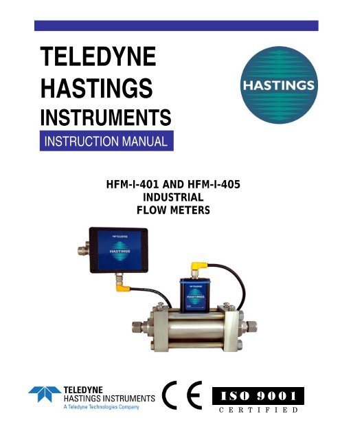
2.4. Mounting the Electronics RemotelyCAUTIONIn order to maintain the integrity of the Electrostatic Dischargeimmunity both parts of the remote mounted version of the <strong>HFM</strong>-I-400 instrument must be screwed to a well grounded structure.The ferrite that is shipped with the instrument must be installedon the cable next to the electronics enclosure.The electronics enclosure can be separatedand relocated up to 30 feet away from theflow meter base. This requires a cable whichis supplied with the instrument if ordered asa cable mounted unit. Alternatively, a 2, 5,or 10 meter cable can be purchasedseparately. See section 4.2 for orderinginformation and part numbers.When remote mounting the electronicsenclosure, the support bracket can remainattached to either the flow meter base or theelectronics. To separate the electronicsenclosure from the support bracket, removethe two screws located on the back of thesupport bracket. To separate the flow meterbase from the support bracket, remove thefour screws that mount the bracket to the topof the flow meter base. Unscrew theelectrical connector between electronics enclosure and the flow meter base. Remove the electronicsenclosure from the flow meter base. Connect the female endof the remote electronics cable to the flow meter base andthe male end to the electronics enclosure. The electronicsenclosure can be mounted remotely by using the twothreaded holes in the enclosure. The size and spacing ofthese two holes are specified on the outline drawing inAppendix 3 (Section 6.3). These holes may be used byinserting fasteners from behind through a new mountingbracket or they may be accessed from the front side bytemporarily removing the enclosure panel. This enablesmounting the enclosure to a wall or other solid structure.Alternatively, if the instrument was originally configured asa bracket mounted unit the bracket may be directlymounted to a support structure. The bracket mountingholes locations are the same as those for the flow meter basemounting. (See the outline drawing in Appendix 3, Section6.3.)2.5. Electrical ConnectionThere are two electrical connectors on the <strong>Hastings</strong> 400-ISeries flow meters—an analog terminal strip (locatedwithin the electronics enclosure) and a digital connector.The analog connector provides for the power supply tothe meter along with analog signals and functions. Assuch, its use is required for operation. The digitalconnector is used for communications in either of RS232,RS485, or Ethernet mode depending on the instrument’sFigure 2-1 Accessing the terminal stripTerminal Strip Pin-out(Pins numbered right to left asviewed from the front)1 - Power Supply2 + Power Supply3 - Flow Output4 + Flow Output5 + Auxiliary Input6 - Auxiliary Input7 No Connection8 Digital Common9 Remote Zero10 Alarm 111 Alarm 212 Alarm CommonFigure 2-2 Electricalconnections for analoginputs/outputs and powerconfiguration. The digital connector does not have to be used if the meter is operated as an analogonlyinstrument.<strong>401</strong>-<strong>405</strong> SERIES - 5 -
There are two possible connection methods to the analog terminalstrip. The standard method is by inserting a cable through thesupplied cable gland with an external jacket that meets thespecifications of the following caution note and tightening down thecable gland nut securely to seal against the cable jacket.There is also an optional sealed circular connector that may be orderedwith the instrument. If this connector is ordered the internal terminalboard will be connected to pins on the circular connector. This optionwill be supplied with the mating connector (if a power cable was notordered with the instrument). This mating connector has pins that mustbe soldered to wires (24 - 28 AWG) in a customer supplied cable thatmeets the specifications in the caution note below. Other sealing collets for cable diameters other thanspecified below can be ordered from Bulgin PX0482 (3 – 5 mm) or PX0483 (5 – 7 mm). Ensure thatthe parts are installed on the cable assembly correctly before assembling. Installation and removal of theouter housing may damage the latches and prevent the connector from making a leak-free seal.CAUTIONIn order to maintain the environmental integrity of the enclosurethe power/signal cable jacket must have a diameter of 0.12 -0.35” (3 – 9 mm) for the cable gland or 0.25 - 0.275” (6.5 – 7mm) for the circular connector. The nut on the cable gland mustbe tightened down sufficiently to secure the cable. This cablemust be rated for at least 85°C.2.5.1. Power SupplyEnsure that the power source meets the requirements detailed in the specifications section. <strong>Hastings</strong>offers several power supply and readout products that meet these standards and are CE marked. Ifmultiple flow meters or other devices are sharing the same power supply, it must have sufficientcapability to provide the combined maximum current.Power is delivered to the instrument through pins 1 and 2 of the analog terminal strip located within theelectronics enclosure (see Figure 2-1). As shown in the pin-out diagram Figure 2-2, the positive polarityof the power supply is connected to pin 2 and the negative is connected to pin 1. (For a unipolar powersupply, pin 1 is power common and pin 2 is +24V. For a bipolar ±15V power supply, pin 1 is -15V andpin 2 is + 15V.) To allow for inadvertent reversal of the power polarity, an internal diode bridge willensure that the proper polarity is applied to the internal circuitry. A green LED located next to theterminal strip will illuminate when the meter is properly powered. The power supply inputs aregalvanically isolated from all other analog and digital circuitry.2.5.2. Analog OutputThe indicated flow output signal is found on pins 3 and 4 of the terminal strip as shown in Figure 2-2.The negative output pin 3 is galvanically isolated from chasis ground and from the power supply inputcommon. The 400 Series meters can be configured to provide one of many available current and voltageoutputs; the standard 4 -20 mA or the optional 0 -20 mA, 0-5 Vdc, 1-5 Vdc, or 0-10 Vdc.NOTEWhen the meter is configured with milliamp output itcannot generate a signal that is below the zero currentvalue; therefore the 0-20 mA unit is limited in its abilityto indicate a negative flow with the analog signal.2.1.1.1. Current Loop OutputThe standard instrument output is a 4 - 20 mA signal proportional to the measured flow (i.e. 4 mA =zero flow and 20 mA = 100% FS). An optional current output of 0 – 20 mA (where 0 mA = zero flowand 20 mA = 100% FS) may be selected at the time of ordering.If either current loop output has been selected, the flow meter acts as a passive transmitter. It neithersources nor sinks the current signal. The polarity of the loop must be such that pin 4 is at a higherpotential than pin 3 on the flow meter terminal strip. Loop power must be supplied with a potential in<strong>401</strong>-<strong>405</strong> SERIES - 6 -
the range of 5-28 Vdc from a source external to the flow meter. The loop supply can be the same supplyas that for the instrument power or it can be an isolated loop supply.Figure 2-3 shows a typical setup using the same supply. This method requires a jumper from pin 2 topin 4 on the terminal strip while connecting pin 3 to a wire that carries this signal to the indicator (forexample, a process ammeter, data acquisition system, or PLC board). To complete the current loop,another wire carries the return signal from the flow indicator back to the negative end of the inputsupply.(Alternatively, the loop current can be measured on the “high potential side” by connecting theindicator between the pins 2 and 4 while connecting pin 3 to pin 1.)Figure 2-4 shows an arrangement using a separate loop supply which is isolated from the instrumentpower supply.<strong>401</strong>-<strong>405</strong> SERIES - 7 -
Figure 2-3 Wiring diagram showing the current loop supply powered by the instrument supplyFigure 2-4 Wiring diagram showing the current loop powered by an external supply<strong>401</strong>-<strong>405</strong> SERIES - 8 -
2.1.1.2. Voltage outputIf the flow meter is configured for a voltage output, the signal will be available as a positive potential onpin 4 relative to pin 3 of the terminal strip. Since these pins are galvanically isolated, the signal cannotbe read by an indicator between pin 4 and pin 1 of the terminal strip. Pin 3 must be used as the returnto properly read the output on pin 4. If an output that is referenced to power supply common is desiredthen pins 3 and 1 must be connected. It is recommended that these signals be transmitted throughshielded cable, especially for installations where long cable runs are required or if the cable is locatednear equipment that emits RF energy or uses large currents.Note: When the meter is configured with a voltage output it cannot generate a signal that is more than afew mV below the zero volt value; therefore the 0-5 volt and 0-10 volt units are limited in their ability toindicate a negative flow with the analog signal.2.6. Digital ConnectionThe digital signals are available on a sealed female D-coded M12 connector that is designed for use onindustrial Ethernet connections. There are many options for connecting to the M12. <strong>Hastings</strong> offers an8 foot cable (stock# CB-RS232-M12) with a compatible male M12 connector to a 9-pin D connectorsuitable for connecting the 400 I series instrument directly to the RS232 port on a PC. A cable toconvert USB to RS232 9-pin is available from <strong>Hastings</strong> (stock# CB-USB-RS232). Also, a 5 meter M12male–male cable suitable for digital communications can be purchased from <strong>Hastings</strong> (stock# CB-ETHERNET-M12). Other length cables are available from Lumberg (#0985 342 100/5 M) or Phoenix.Converters from the M12 connector to a standard modular Ethernet connector are available from<strong>Hastings</strong> or from Lumberg (#0981 ENC 100). A compatible M12 connector suitable for field wiringcan be acquired from Harting (21 03 281 1<strong>405</strong>) or Mouser (617-21-03-281-1<strong>405</strong>).The pin-out for the digital connector is shown in Figure 2-5.PINSRS232RS485ETHERNET1 243SHIELD1234GROUNDTRANSMITRECEIVEUNUSEDUNUSEDGROUNDTX+ (A)RX+ (A)TX- (B)RX- (B)GROUNDTD+RD+TD-RD-Figure 2-5 Digital connector pin-out2.7. Digital ConfigurationA <strong>Hastings</strong> 400-I Series flow meter is available with oneof three digital communications interfaces, RS232,RS485, or Ethernet. Unless specified differently at thetime of ordering, the flow meter is configured for RS232operation. For each interface, there are changes that canbe made to the configuration, either via software orhardware settings. A brief overview of these is includedhere. For more detailed information, consult the<strong>Hastings</strong> 400 Series Software Manual.2.7.1. RS-232Jumper Enabled Disabled1 RS485 RS2322 Half Duplex Full Duplex3 TX Terminated Unterminated4 RX Terminated Unterminated5 9600 Baud Software Selected6 Addr = 99 Software SelectedThe default configuration for the RS-232 interface is19200 baud, 8 data bits, no–parity, one stop bit. The Figure 2-6 Functions for digital jumper fieldbaud rate is software selectable and can be overriddenby a hardware setting. Hardware settings for RS-232 and RS-485 are enacted on 12 pin jumper fieldlocated on the left end of the top circuit board in the electronics enclosure. Only the state of jumpers 1,2, and 5 affect the RS-232 operation. These jumpers are installed vertically over two pins when enabledand are numbered from left to right. Jumper 1 must be disabled for RS-232; jumper 2 is used to select<strong>401</strong>-<strong>405</strong> SERIES - 9 -
half or full duplex; and jumper 5 is enabled when a hardware override of the baud rate (forcing it to9600) is desired. These functions are summarized in Figure 2-6.2.7.2. RS-485If RS485 is specified on the order, the flow meter isset to the default values: address 61, unterminated Txand Rx lines. While the default address is 61, allinstruments will respond to an address of FF.Hardware settings for RS-232 and RS-485 areenacted on 12 pin jumper field located on the left endof the top circuit board in the electronics enclosure.Only the state of jumpers 1, 3, 4, and 6 affect the RS-485 operation (see Figure 2-6). These jumpers areinstalled vertically over two pins when enabled andare numbered from left to right. Jumper 1 must beenabled for RS-485. Enabling jumpers 3 and 4 effecta 120 ohm resistance across the transmit and receivesignal pairs respectively. These should only beenabled in the last instrument on a long buss.Enabling jumper 6 forces the address to 99; this issometimes used when initiating communications.Figure 2-7 Web browser screen2.7.3. EthernetIf Ethernet is specified on the order, the flow meter has IPaddress 172.16.52.250 and communication port number10001. There are no hardware settings required or availableto modify the configuration. This IP address can be changedusing a web browser to access the configuration of theinstrument by typing the IP address into the URL section ofthe browser. Press OK to ignore the username/passwordscreen as shown in Figure 2-7. Select the new IP addressunder the network section of the web page configurationutility. If this address cannot be reached, the instrument canbe reconfigured by downloading and installing the LantronixDevice Installer routine from:http://www.lantronix.com/device-networking/utilitiestools/device-installer.html.A standard web browser cannot be used to send and receivemessages (such as flow readings) from the main processor ofthe flow meter. An Ethernet capable software program isrequired to communicate with the meter’s processor.Suitable examples of such programs are “Hyperterminal”(typically installed as standard on PCs and shown in Figure2-8) or custom Ethernet capable software such as LabView ® .For more information see the Software Manual.Figure 2-8 Example Hyperterminal window2.8. Alarm Output ConnectionThe <strong>Hastings</strong> 400 Series flow meters include two software settable hardware alarms. Each is an opencollectortransistor functioning as a semiconductor switch designed to conduct DC current whenactivated. (See Figure 2-9.) These sink sufficient current to illuminate an external LED or to activate aremote relay and can tolerate up to 70Vdc across the transistor. The alarm lines and the alarm commonare galvanically isolated from all other circuit components. The connections for Alarm 1, Alarm 2 andAlarm Common are available as pins 10, 11, and 12 respectively on the analog terminal strip (see QuickStart Guide on page iii).<strong>401</strong>-<strong>405</strong> SERIES - 10 -
Since the alarms act as switches they do not producea voltage or current signal. However, they can beused to generate a voltage signal on an Alarm Outline. This is done by connecting a suitable pull-upAlarm 1resistor between an external voltage supply and thedesired alarm line while connecting Alarm Commonto the common of the power supply. When activated,the alarm line voltage will be pulled toward the alarmcommon line generating a sudden drop in the signalAlarm 2line voltage.To use the alarm to illuminate an LED connect thepositive terminal of the LED to a suitable powersupply and connect the other end to a currentlimiting resistor. This resistor should be sized suchthat the current is less than 20 mA when the entiresupply voltage is applied. Connect the other end ofFigure 2-9 Alarm circuit diagramthe resistor to Alarm 1 or Alarm 2. Connect AlarmCommon to the circuit common of the power supply. When activated, the alarm line is pulled towardthe alarm common generating sufficient current through the LED to cause it to illuminate.Figure 2-10 shows an example of the LED circuit arrangement applied to Alarm 1 while Alarm 2 isconfigured with a suitable pull-up resistor to provide a voltage output on an Alarm Out line.Since the Alarm Common is ashared contact, if both alarmsare being used independentlythey must each be wired suchthat the current passesAlarm 1through the external signalingdevice before reaching theV +alarm line.The alarm settings andactivation status are availablevia software commands andqueries. The softwareinterprets an activated Alarm1 as an “Alarm” condition,while an activated Alarm2 isinterpreted as a “Warning”condition. The softwaremanual includes the detaileddescriptions for configuringand interpreting the activationof these alarms.Alarm 2Alarm CommonAlarm OutV -Alarm Common2.9. Auxiliary InputConnectionFigure 2-10 Alarm circuit diagram for LED operationThe <strong>Hastings</strong> 400 Series flow meters provide an auxiliary analog input function. The flow meter canread the analog value present between pins 5 and 6 on the terminal strip (as shown in Figure 2-2) andmake its value available via the digital interface. The accepted electrical input signal is the same as thatconfigured for the analog output signal (4 – 20 mA, 0 -20 mA, 0-5 Vdc, 1-5 Vdc, or 0-10 Vdc). Unlikethe analog output signal, which is isolated and capable operating at common mode offsets of over1000V, the analog input signal cannot be galvanically isolated from ground potential.<strong>401</strong>-<strong>405</strong> SERIES - 11 -
2.2. Rotary Gas SelectorThe <strong>Hastings</strong> 400 Series flow meters can have up to eight different calibrationsstored internally. These are referred to as gas records. These records are usedto select different gases, but they can also be useful in other ways; for instancereporting the flow in an alternate range, flow unit or reference temperature.The records are referred to by their number label from #0 – #7.The first six records will, by default, be setup for most common six gases asshown in Figure 2-11. If a gas other than one of these six is specified on thecustomer order it will be placed in record #6. If a second different gas isselected, it will be placed in record #7. If multiple different gases or ranges arespecified they will replace some of the standard six gases.The purchased calibration certificate is provided for the gas (orgases) specified by the customer when ordering. This gas will beindicated with an “X” on the Gas Label (diagram below) that islocated on the top of the 400 Series Mass flow meter’s electronicsenclosure. The remaining gas records will have a different full scalevalue and an unverified calibration. The full scale rangecan be calculated by using the Gas conversion factor orGCF. A comprehensive list is found in Appendix 2 inthis manual.X0 N21 Air2 He3 H24 Ar5 O267S/NX= cal reportgenerated(others use GCF)Record#Record# Gas0 Nitrogen1 Air2 Helium3 Hydrogen4 Argon5 Oxygen6 Custom7 CustomFigure 2-11 Gas record tableFull ScaleRangeGas0 Nitrogen 100 slm1 Air 100.15 slm2 Helium 140 slm3 Hydrogen 100.38 slm4 Argon 140.37 slm5 Oxygen 97.95 slm6 Custom7 CustomNot included ifnot specifiedNot included ifnot specifiedExample 1To convert the calibration of a full scale range of 100 slm of Nitrogen to the other full scale ranges:FS = FS21GCFGCF211. Calculate full scale value of HeliumCalibrated gas = Nitrogen (GCF1 = 1.000)Full scale range (FS1) = 100 slmSecondary gas (FS2) = Helium (GCF2 = 1.40)1.40/1 = 1.40, 1.40 x 100 = 140 slm of Helium2. Calculate full scale value of HydrogenCalibrated gas = Nitrogen (GCF1 = 1.000)Full scale range (FS1) = 100 slmSecondary gas (FS2) = Hydrogen (GCF2 = 1.0038)1.0038/1 = 1.0038, 1.0038 x 100 = 100.38 slm of Hydrogen<strong>401</strong>-<strong>405</strong> SERIES - 12 -
Example 2- Changing the active gas recordSelecting the active gas record is accomplished in one of two ways:1. Hardware setting2. Software settingHardware:The hardware setting is selected by accessing a rotary encoder on the upper PC board in the electronicsenclosure. When set to a number position from 0 to 7 it activates the corresponding gas record. If anumber greater than 7 is selected, then gas record control is passed to software.Software:See Section 3.9 Multi-Gas Calibrations and the software manual for more information about thesoftware control capabilities.The software setting will override the hardware settings. If gas records are changed through thesoftware setting and the rotary encoder is not changed, the software setting will be active. However,when the meter is powered down and subsequently powered up, the active setting will be based on therotary encoder setting.2.10. Electrical Remote Zero ConnectionThe <strong>Hastings</strong> 400 Series allows the flow meter zeroing operation to be activated remotely using pins 8and 9 of the analog terminal strip. (See Drawing in Quick Start Guide.) If these pins are connectedtogether, the meter initiates an internal routine that measures the current reading, stores it innonvolatile memory as a zero offset, and removes this value from all subsequent readings. When the pin9 is electrically isolated the flow meter operates normally. The typical implementation of this type ofremote zeroing operation involves connecting a remote switch or relay to pins 8 and 9 of the terminalstrip. (For more about the zeroing operation, see Section 3.4)2.11. Check Installation Prior to OperationBefore applying gas to the meter it is advisable to ensure that the mechanical and electrical connectionsand digital communications (if applicable) are established and operating properly. This can be done byfollowing the guideline procedure below:<strong>401</strong>-<strong>405</strong> SERIES - 13 -
<strong>401</strong>-<strong>405</strong> SERIES - 14 -
3. Operation3. OperationThe <strong>Hastings</strong> 400 Series flow meters are designed for operation with clean dry gas and in specifiedenvironmental conditions (See Section 1.2). The properly installed meter measures and reports themass flow as an analog signal and, depending on the configuration and set up, as a digital response.Other features can assist in the measurement operation and provide additional functions. The followingsections serves as a guide for correctly interpreting the analog and digital flow output, optimizing theperformance, and using the additional features of the instrument.3.1. Environmental and Gas ConditionsFor proper operation, the ambient and gas temperatures must be such that the flow meter remainsbetween -20 and 70°C. Optimal performance is achieved when the environment and gas temperaturesare equilibrated and stable. The 400 I series is intended for use with clean, non-condensing gases only.Particles, contamination, condensate, or any other liquids which enter the flow meter body mayobstruct critical flow paths in the sensor or shunt, thus causing erroneous readings.3.2. Interpreting the Analog OutputThe analog output signal is proportional to mass flow rate. Each instrument is configured to provideone of the available forms of analog output as described in Section 2.2. The signal read by an indicator(for example, a process ammeter, data acquisition system, or PLC board) can be mapped to themeasured flow rate by applying the proper conversion equation selected from the table below.Table 3-1 The Signal → Flow mapping equationsAnalog Output ConfigurationMapping Equation4 -20 mA Flow = FS flow * (Iout – 4)/ 160 -20 mA Flow = FS flow * Iout / 200 – 5 Vdc Flow = FS flow * Vout / 50 – 10 Vdc Flow = FS flow * Vout / 101 – 5 Vdc Flow = FS flow * (Vout -1)/ 4Alternatively an analog display meter can indicate the flow rate directly in the desired flow units bysetting the offset and scaling factors properly.The flow meter is typically able to measure and report flow which slightly exceeds the full scale value.Reverse or “negative” flows are indicated (to values up to 25% of full scale) by meters with 4-20 mA or1-5 volt output. However, meters with 0-5 Volt, 0-10 volt or 0-20 mA output are limited in their abilityto indicate a negative flow with the analog signal since negative currents or voltages cannot be generatedby the meter’s circuitry.3.3. Digital CommunicationsMany of the <strong>Hastings</strong> 400 Series flow meter’s operating parameters such as the flow measurement,alarm settings, status, or gas type can be read or changed by digital communications. The digitalcommunications commands and protocols for each particular interface (RS-232, RS-485, and Ethernet)are treated in detail in the Software Manual. However, the function and interpretation of flow outputand auxiliary input are also briefly presented here.<strong>401</strong>-<strong>405</strong> SERIES - 15 -
3.3.1. Digitally Reported Flow OutputThe flow rate can be read digitally by sending an ascii “F” command (preceded by the address for RS-485). The instrument will respond with an ascii representation of the numerical value of the flow rate inthe units of flow specified on the nameplate label.Example: A meter with RS-232 communications, calibrated for 500 slm FS N2Computer transmits: {F}<strong>HFM</strong> flow meter replies: {137.5}This is interpreted as 137.5 slm of nitrogen equivalent flow.In most situations, the flow meter can measure beyond its range (i.e. a flow that exceeds the full scale ora reverse flow) and report the value via the digital output. While the meter can perform beyond itsstated range, the accuracy of these values has not been verified during the calibration process. Flowsthat exceed 160% of the nominal shunt range (S46 response) should not be relied upon. See thesoftware manual for further information.3.3.2. Digitally Reported Analog InputThe flow meter can read the analog value present on pins 5 & 6 of the terminal strip (See Section 2.9).This function is typically used to read the analog output from a nearby sensor such as a pressure sensoror vacuum gauge. This value is spanned for the same range as the analog output signal; it reads volts forflow meter configured for 0-5, 0-10 or 1-5 volt output and milliamps for a flow meter configured for 0-20 or 4-20 milliamp output. The value is accessed via the “S26” software query as shown below.Example: A meter calibrated for 0-5 volt output and RS-232 communications.Computer transmits: {S26}<strong>HFM</strong> flow meter replies: {2.532}This is interpreted as 2.532 volts.3.4. Zeroing the InstrumentA proper zeroing of the flow meter is recommended after initial installation and warm-up. It is alsoadvisable to check the zero flow indication periodically during operation. Any uncertainty at zero flow isan offset value which affects all subsequent flow readings. The frequency of these routine checksdepends on factors such as: the environmental conditions, the desired level of accuracy, and the desireto measure low flow rates (relative to the meter full scale). To achieve the most precise flow readings,the zeroing procedure is done while the meter is at the expected operating conditions includingtemperature, line pressure, and gas type. This is especially true for cases where the flow meter isoperating at high pressure or with very dense gas.3.4.1. Preparing for a Zero CheckBefore checking or adjusting the meter’s zero, the following three requirements must be satisfied:Warm-up – The instrument must be powered and in the operating environment for at least 30minutes. Even though the meter will operate within a few minutes after power is applied, the entirewarm-up period is needed to establish a suitable zero reading.No Flow – There must be an independent method to ensure that all flow through the instrument hascompletely ceased before checking or adjusting the zero. Typically this is achieved by closing valvedownstream from the flow meter and waiting a sufficient time for any transient flow to decay. This isespecially critical for low flow units that have long piping lengths before or after the flow meter. In suchsituations, it can require a significant settling time for the flow cease and enable a precise zero.Stability – The flow meter must stabilize for at least 3 minutes at zero flow, especially following a highflow or overflow condition. This will allow all parts of the sensor to come to thermal equilibriumresulting in the best possible zero value.<strong>401</strong>-<strong>405</strong> SERIES - 16 -
3.4.2. Adjusting ZeroThe pre-conditions required for a zero check must also be followed when making a zero adjustment.The zero adjustment is a digitally controlled “reset” type operation. When commanded, the meterinitiates an internal routine that performs the following sequence: measure the current flow reading,store it in nonvolatile memory as a zero offset, and remove this value from all subsequent readings.NOTEIf the instrument is inadvertently or improperly zeroed, forexample while flow is passing through the instrument, the flowreading is subtracted from all future flow readings. This willproduce large flow indication errors.This offset value can be accessed via the “S40” software query. The reported value is relative to aninternal, un-spanned sensor voltage. As an interpretation guideline, an offset that exceeds 0.15 voltstypically indicates that a faulty zero value is present.There are three different methods to activate the zero reset function--manually, digitally, andelectrically.Manually – With the electronics enclosure cover plate removed, a pushbutton switch on the upperboard is pressed.CAUTIONAccessing the manual zero pushbutton requires removing theenclosure front plate. Care must be taken when reinstalling thisplate to ensure that the sealing gasket is properly positioned andthe fasteners are secure to maintain an IP65 compliant seal.Digitally – A “ZRO” (“*[address]ZRO” for RS485) command is received properly by the flow meter’smain processor.Electrically – An external contact closure generates continuity between pins 8 and 9 of the terminalstrip.3.4.2.3.5. Over-rangeThe thermal mass flow sensor heats a portion of the gas in order to measure the flow rate. As the flowincreases the heated tube is cooled and the slope of the sensor output versus the flow rate decreases.The sensor linearization function corrects for this effect while the flow rate is within the normaloperating region. If the flow exceeds the normal operating region the digital flow indication willcontinue to track this increase with a reduced accuracy. The analog flow will also indicate this overflowcondition until the circuitry reaches its limits (approximately 10 -25% over-range).As the flow continues to increase above the normal operating region the sensor will be cooledsufficiently that the output of the sensor will reach a peak value around 2 – 4 times the full scale flowrate. If the flow continues to increase the sensor output will begin decreasing and the digital flow willindicate a decreasing flow rate even though the flow is actually getting increasing. At approximately 3 –7 times the full scale flow rate the sensor output will drop within range of the normal output and eventhe analog output will record an on-scale flow rate when there is a very large over range flow rate.<strong>401</strong>-<strong>405</strong> SERIES - 17 -
250%Flow meter OutputIndicated Flow (% Full Scale)200%150%100%50%Analog OutputDigital Output0%0% 100% 200% 300% 400% 500% 600%Flow (% Full Scale)3.4.2.3.6. Reverse FlowIf the flow through the flowmeter reverses and flowbegins to enter the exit of theflow meter and leave throughthe entrance of the flow meterthe flow meter will measurethis flow and report it digitallywith reduced accuracy. Theanalog output will alsoindicate this by eithergenerating a negative outputvoltage or decreases thecurrent output below 4 mA,depending on whether avoltage or current output hasbeen selected.3.7. High PressureOperationWhen operating at highpressure, the meter’sperformance can be affectedin two distinct and separateways—a zero shift and a span(calibration) shift.Span Shift (% Reading)Pressure Effect876543210-10 200 400 600 800 1000Line Pressure (psig)Figure 3-1 The pressure effect on flow calibration (for nitrogen)<strong>401</strong>-<strong>405</strong> SERIES - 18 -
3.7.1. Zero ShiftThe zero offset can occur as the result of natural convection flow through the sensor tube if theinstrument is not mounted in a level orientation with flow horizontal. This natural convection effectcauses a zero shift proportional to the system pressure. The overall effect is more pronounced for gaseswith higher density. Normally the shift is within the allowable zero offset range and can be removed byactivating the zero reset at the operating pressure.3.7.2. Span ShiftThe gas properties which form the basis for the flow measurement, such as viscosity and specific heat,exhibit a slight dependence on the gas pressure. Fortunately, this pressure dependence is predictableand can be corrected for in cases where it has an impact on accuracy (typically only significant forpressures in excess of 100 psig). The graph shown in Figure 3-1 shows the expected span shift as afunction of pressure for nitrogen. This behavior is similar for most diatomic gases (O2, H2, etc), whereasthis effect is insignificant for the monatomic gases (He, Ar, etc). This span shift must be considered andaccounted for as appropriate for accurate flow measurements at high pressure conditions.3.8. Warnings/AlarmsThere are two alarm contacts on the terminal strip connector within the electronics enclosure (SeeSection 2.8). These function as isolated semiconductor switches sharing a single, isolated common line.In its normal state each switch is “open”; when an alarm is activated the switch is “closed”.The meter’s processor can be configured via the digital interface to establish the internal condition foractivating each alarm. There are many choices for internal alarms and warnings including overflow,underflow, or various instrument error conditions. Each alarm can also be given a selectable “waittime”—a period for which it must remain in the alarm condition before the physical alarm is activated.See the Software Manual for detailed alarm setting and configuration information.3.9. Multi-gas CalibrationsThe <strong>Hastings</strong> 400 Series flow meters can have up to eight different calibrations stored internally. Theseare referred to as gas records. These records are typically used to represent different gases, but they canalso be useful in other ways; for instance reporting the flow in an alternate range, flow unit or referencetemperature. The records are referred to by their number label from #0 – #7. The first six records are,by default, setup for the same range in the most common six gases as shown in Figure 2-11. If a gasother than one of these six is specified on the customer order it will be placed in record #6. If a seconddifferent gas is selected, it will be placed in record #7. If multiple different gases or ranges are specifiedthey will replace some of the standard six gases. Only the gas(es) specified on the order will be verified.The other records will use nominal gas factors to approximate the gas sensitivity until an actualcalibration is performed to correct for individual instrument variations. Selecting the active gas recordcan be done in one of two ways—a hardware setting or a software setting. The hardware setting is doneby accessing a rotary encoder on the upper PC board in the electronics enclosure. When set to anumber position from 0 to 7 it activates the corresponding gas record. When set to a number greaterthan 7, the gas record control is passed to software. If the software setting mode is enabled, then the“S6” digital command can be used to set the active gas record as shown in the example below.Example: To first determine and then change the active gas record using RS-232,Computer transmits: {S6}<strong>HFM</strong> flow meter replies: {0}This indicates that gas record #0 is currently active.Computer transmits: {S6=4}This changes the active gas record to #4.See the Software Manual for further information including how to setup a new gas record and how toreconfigure an existing gas record.<strong>401</strong>-<strong>405</strong> SERIES - 19 -
CAUTIONAccessing the rotary encoder requires removing the enclosurefront plate. Care must be taken when reinstalling this plate toensure that the sealing gasket is properly positioned and thefasteners are secure to maintain an IP65 compliant seal.NOTEThe software command to change the active gas record will notbe executed unless the rotary encoder is set to a number greaterthan 7. However, the software query will return the current activegas record number even when it has been set by the hardware.3.10. Flow TotalizationThe <strong>Hastings</strong> 400 Series flow meters are capable of providing a value for the “total amount of gas” thathas passed through the flow meter since the last time the totalization function was reset. This value canbe used to determine for example, the amount of gas used to fill a chamber or drawn from a supplyvessel. To initialize the totalization function, reset the totalized flow value to zero using the S36 digitalcommand as shown in the example below. All subsequent flow readings are added over time and storedas the totalized flow value. The totalized flow value can be read by querying the flow meter digitally asin the example below. The totalized flow is reported in the flow units chosen for the active gas withoutthe time unit. For example, if the flow units are standard liters per minute, the totalized flow is reportedin standard liters; if flow units are standard cubic feet per hour, the totalized flow is reported in standardcubic feet.Example: For a 100 slm FS flow meter, to first reset/start the flow totalization function and then later read thevalue using RS-232,Computer transmits: {S36=0}This resets the totalized value to zero and starts the totalization function. At some point later in time:Computer transmits: {S36}<strong>HFM</strong> flow meter replies: {45.7}This is interpreted as a total gas amount of 45.7 standard liters has passed through the meter since the flowtotalizer was started.3.11. Additional Digital CapabilitiesThe <strong>Hastings</strong> 400 series flow meters have a wide selection of other functions, operating parameters, andvalues that can be reported and configured via digital communications such as the calibration date, theinstrument temperature, the number of hours that gas has been flowing, etc. See the Software Manualfor detailed information on these additional digital features.<strong>401</strong>-<strong>405</strong> SERIES - 20 -
4. Parts and Accessories4. Parts & accessoriesThese are parts and accessories that are available by separate order from <strong>Teledyne</strong> <strong>Hastings</strong> <strong>Instruments</strong>.4.1. Power Pod – Power & Display unitsTHPS-100 Singel Channel Power SupplyThe <strong>Teledyne</strong> <strong>Hastings</strong> <strong>Instruments</strong> microprocessor based Power Pod -100 ThermalMass Flow Power Supply is a self-contained power supply and display for gas thermalmass flow meters, pressure transducers or any device with a voltage output. The unitfeatures an automatically generated set point (0-5V or 0-10V), making it ideal for usewith thermal mass flow controllers and pressure controllers. Features include4.5display, ±15 volt, 250mA transducer supply and an integrated +/- 15vdc @ 250mapower supply is available providing a well regulated, short circuit and thermal overloadprotected output, and CE compliance.See the <strong>Teledyne</strong> <strong>Hastings</strong> <strong>Instruments</strong> Product Bulletin for the complete specificationon this product.THPS-400 Four Channel Power SupplyThe <strong>Teledyne</strong> <strong>Hastings</strong> <strong>Instruments</strong> Digital 4-Channel Power Pod is featured in a halfrackprofile for simple drop-in replacement of the existing Model 200 and 400 units,or be used as a bench top unit.The Power Pod -400 is equipped with a four line by twenty-character, vacuumfluorescent display (VFD). The display emulates a liquid crystal display in itscommand structure but the VFD gives the unit a greater viewing angle than availablewith most conventional LED or LCD displays.The Power Pod incorporates many features including an integrated totalizer with acount-up or count-down option; user selected filtering of readings; serial or Ethernetcommunications.The unit also offers a simultaneous display of all four channels or selective blanking ofunused channels, ratio control with analog outputs for stacking multiple powersupplies, and easy to follow menu driven calibration and setup.The digital design of the Power Pod allows the user to set both the minimum andmaximum display values corresponding to specific voltage or current inputs. Oneadvantage of this approach is that it negates the need to access hard to reachtransducers to re-zero them. Should the analog signal from the transducer change dueto a zero shift, the digital counts seen by the Power Pod can be changed to display zeroeither manually from the front panel or via serial communication with the unit.<strong>401</strong>-<strong>405</strong> SERIES - 21 -
4.1. FittingsFittings<strong>Hastings</strong>#<strong>HFM</strong>-I-<strong>401</strong>1/2" Swagelok Fittings 41-03-0861/2" VCO Fittings 41-03-1191/2" VCR Fittings 41-03-0903/4" Swagelok Fitting 41-03-15210 mm Swagelok 41-03-1533/8" Male NPT 41-03-1541/2" Male NPT 41-03-15512 mm Swagelok 41-03-1603/4-16 SAE/MS Straight Female (no fitting) N/A<strong>HFM</strong>-I-<strong>405</strong>1" Swagelok fitting 41-03-1423/4" Swagelok 41-03-1491" VCO Fitting 41-03-1471" VCR fitting 41-03-1481" Male NPT 41-03-1503/4" Male NPT 41-03-1511 5/16-12 Female SAE/MS straight thread (no fitting) N/A4.2. CablesDescription<strong>Hastings</strong>Stock#Remote Electronics Cables2 meter cable remote mounting cable CB-8P-M12-2MRA5 meter remote mounting cable CB-8P-M12-5MRA10 meter remote mounting cable CB-8P-M12-10MRA<strong>401</strong> Local Bracket - mount direct to sensor 14-03-002<strong>405</strong> Local Bracket - mount direct to sensor 14-03-001Digital Communications9 pin RS232 to 400 series M12 connector CB-RS232-M12Digital M12 connector to M12 connector CB-ETHERNET-M12USB to 9 pin RS232 connectorCB-USB-RS232RJ45 Ethernet to M12 Ethernet connector CB-RJ45-M12Analog I/O8 foot D connector to 8 bare leads CB-D15-Lead-825 foot D connector to 8 bare leads CB-D15-Lead-25100 foot D connector to 8 bare leads CB-D15-Lead-100<strong>401</strong>-<strong>405</strong> SERIES - 22 -
5. WARRANTY5. Warranty5.1. Warranty Repair Policy<strong>Hastings</strong> <strong>Instruments</strong> warrants this product for a period of one year from the date of shipment to be freefrom defects in material and workmanship. This warranty does not apply to defects or failures resultingfrom unauthorized modification, misuse or mishandling of the product. This warranty does not apply tobatteries or other expendable parts, nor to damage caused by leaking batteries or any similar occurrence.This warranty does not apply to any instrument which has had a tamper seal removed or broken.This warranty is in lieu of all other warranties, expressed or implied, including any implied warranty asto fitness for a particular use. <strong>Hastings</strong> <strong>Instruments</strong> shall not be liable for any indirect or consequentialdamages.<strong>Hastings</strong> <strong>Instruments</strong>, will, at its option, repair, replace or refund the selling price of the product if<strong>Hastings</strong> <strong>Instruments</strong> determines, in good faith, that it is defective in materials or workmanship duringthe warranty period. Defective instruments should be returned to <strong>Hastings</strong> <strong>Instruments</strong>, shipmentprepaid, together with a written statement of the problem and a Return Material Authorization (RMA)number.Please consult the factory for your RMA number before returning any product for repair. Collect freightwill not be accepted.5.2. Non-Warranty Repair PolicyAny product returned for a non-warranty repair must be accompanied by a purchase order, RMA formand a written description of the problem with the instrument. If the repair cost is higher, you will becontacted for authorization before we proceed with any repairs. If you then choose not to have theproduct repaired, a minimum will be charged to cover the processing and inspection. Please consult thefactory for your RMA number before returning any product repair.TELEDYNE HASTINGS INSTRUMENTS804 NEWCOMBE AVENUEHAMPTON, VIRGINIA 23669 U.S.A.ATTENTION: REPAIR DEPARTMENTTELEPHONE (757) 723-65311-800-950-2468FAX (757) 723-3925E MAILhastings_instruments@teledyne.comINTERNET ADDRESS http://www.hastings-inst.comRepair Forms may be obtained from the “Information Request” section of the<strong>Hastings</strong> <strong>Instruments</strong> web site.<strong>401</strong>-<strong>405</strong> SERIES - 23 -
6. Appendices6. Appendices6.1. Appendix 1- Volumetric versus Mass FlowMass flow measures just what it says, the mass or weight of the gas flowing through the instrument.Mass flow (or weight per unit time) units are given in pounds per hour (lb/hour), kilograms per sec(kg/sec) etc. When your specifications state units of flow to be in mass units, there is no reason toreference a temperature or pressure. Mass does not change based on temperature or pressure.However, if you need to see your results of gas flow in volumetric units, like liters per minute, cubic feetper hour, etc. you must consider the fact that volume DOES change with temperature and pressure.A mass flow meter measures MASS (grams) and then converts mass to volume. To do this the density(grams/liter) of the gas must be known and this value changes with temperature and pressure.When you heat a gas, the molecules have more energy and they move around faster, so when theybounce off each other, they become more spread out, therefore the volume is different for the samenumber of molecules.Think about this:The density of Air at 0° C is 1.29 g/literThe density of Air at 25C is 1.19 g/literThe difference is 0.1 g/liter. If you are measuring flows of 100 liters per minute, and you don’t use thecorrect density factor then you will have an error of 10 g/minute!Volume also changes with pressure. Think about a helium balloon with a volume of 1 liter. If youcould scuba dive with this balloon and the pressure on it increases. What do you think happens to theweight of the helium? It stays the same. What would happen to the volume (1 liter)? It would shrink.Why is the word standard included with the volume terms liters and cubic feet in mass flowapplications?A mass flow meter measures mass …and we know we can convert to volume.To use density we must pick one (or standard) temperature and pressure to use in our calculation.When this calculation is done, the units are called standard liters per minute (SLM) or standard cubicfeet per minute (SCFM), etc because it is referenced to a standard temperature and pressure when thevolume is calculated.Using the example to the left, we can see astandard liter can be defined differently. Thefirst balloon contains 0.179 grams of Helium at0 ° C and 760 Torr (density of 0.179grams/liter). Heat up that balloon to roomtemperature and the volume increases, but themass has not changed – but the volume is not 1liter anymore, it is 1.08 liters.So to define a standard liter of Helium at 25 C,we must extract only one liter from the secondballoon and that liter weighs only 0.175 grams.If a mass flow meter is set up for STP at 0 C and1 Liter 1.08 Liter 1 Liter760 Torr, when it measures 0.179 grams of He,it will give you results of 1 SLM.0° C25 C25° C0..179 grams/1 0.179 g/1.08 0.164 grams If a second meter is set up for STP at 25 C andliterliters760 Torr, when it measures 0.164 grams, it willgive results of 1 SLM.<strong>401</strong>-<strong>405</strong> SERIES - 24 -
6.2. Appendix 2 - Gas Conversion FactorsThe gas correction factors (GCF’s) presented in this manual were obtained by one of four methods.The following table summarizes the different methods for determining GCF’s and will help identify forwhich gases the highest degree of accuracy may be achieved when applying a correction factor.1. Empirically determined2. Calculated from virial coefficients of other investigator’s empirical data3. From NIST tables4. Calculated from specific heat data at 0° C at 1 atmosphereThe most accurate method is by direct measurement. Gases that are easily handled with safety such asinert gases, gases common in the atmosphere or gases that are otherwise innocuous can be run througha standard flow meter and the GCF determined empirically.Many gases that have been investigated sufficiently by other researchers, can have their molar specificheat (C’ p) calculated. The gas correction factor is then calculated using the following ratio:GCF = C ’apN2C’apGasXGCF’s calculated in this manner have been found to agree with the empirically determined GCF’swithin a few tenths of a percent.The National Institute of Standards[LH1] and Technology (NIST) maintains tables of thermodynamicproperties of certain fluids. Using these tables, one may look up the necessary thermophysical propertyand calculate the GCF with the same degree of accuracy as going directly to the referenced investigator.Lastly, for rare, expensive gases or gases requiring special handling due to safety concerns, one may lookup specific heat properties in a variety of texts on the subject. Usually, data found in this manner appliesonly in the ideal gas case. This method yields GCF’s for ideal gases but as the complexity of the gasincreases, its behavior departs from that of an ideal gas. Hence the inaccuracy of the GCF increases.<strong>Hastings</strong> <strong>Instruments</strong> will continue to search for better estimations of the GCF’s of the difficult gasesand will regularly update the list. Most <strong>Hastings</strong> flow meters and controllers are calibrated usingnitrogen. The correction factors published by <strong>Hastings</strong> are meant to be applied to these instruments. Toapply the GCF’s, simply multiply the gas flow reading times the GCF for the process gas in use.Example:Calculate the actual flow of argon passing through a nitrogen-calibrated meter that reads 20 sccm,multiply the reading times the GCF for argon.20.000 x 1.3978 = 27.956Conversely, to determine what reading to set a nitrogen-calibrated meter in order to get a desired flowrate of a process gas other than nitrogen, you divide the desired rate by the GCF. For example, to get adesired flow of 20 sccm of argon flowing through the meter, divide 20 sccm by 1.397820.000 / 1.3978 = 14.308That is, you ` (adjust the gas flow) to read 14.308 sccm.<strong>401</strong>-<strong>405</strong> SERIES - 25 -
Some meters, specifically the high flow meters, are calibrated in air. The flow readings must then becorrected twice. Convert once from air to nitrogen, then from nitrogen to the gas that will be measuredwith the meter. In this case, multiply the reading times the ratio of the process gas’ GCF to the GCF ofthe calibration gas.Example:A meter calibrated in air is being used to flow propane. The reading from the meter is multiplied by theGCF for propane and then divided by the GCF of air.20 x (0.3499/1.0015) = 6.9875To calculate a target setting (20 sccm) to achieve a desired flow rate of propane using a meter calibratedto air, invert the ratio above and multiply.20 x (1.0015/0.3499) = 57.2449Gas Conversion Table for NitrogenRec# Gas Symbol GCF DerivedDensity(g/L) Z25° C / 1atm1 Acetic Acid C 2 H 4 F 2 0.4155 4 2.700 2.03012 Acetic Acid, Anhydride C 4 H 6 O 3 0.2580 4 4.173 2.33843 Acetone C 3 H 6 O 0.3556 4 2.374 1.75044 Acetonitryl C 2 H 3 N 0.5178 4 1.678 1.44625 Acetylene C 2 H 2 0.6255 4 1.064 0.97926 Air Air 1.0015 1 1.185 1.09307 Allene C 3 H 4 0.4514 4 1.638 1.38768 Ammonia NH 3 0.7807 2 0.696 0.64099 Argon Ar 1.4047 1 1.633 2.124310 Arsine AsH 3 0.7592 5 3.186 4.083911 Benzene C 6 H 6 0.3057 4 3.193 2.063612 Boron Trichloride BCl 3 0.4421 4 4.789 3.653113 Boron Triflouride BF 3 0.5431 4 2.772 2.410914 Bromine Br 2 0.8007 4 6.532 1.000015 Bromochlorodifluoromethane CBrClF 2 0.3684 4 6.759 4.278916 Bromodifluoromethane CHBrF 2 0.4644 4 5.351 4.399017 Bromotrifluormethane CBrF 3 0.3943 4 6.087 4.154618 Butane C 4 H 10 0.2622 2 2.376 1.689619 Butanol C 4 H 10 O 0.2406 4 3.030 1.923320 Butene C 4 H 8 0.3056 4 2.293 1.670021 Carbon Dioxide CO 2 0.7526 1 1.799 1.751122 Carbon Disulfide CS 2 0.6160 4 3.112 3.074423 Carbon Monoxide CO 1.0012 4 1.145 1.043324 Carbon Tetrachloride CCl 4 0.3333 4 6.287 3.619625 Carbonyl Sulfide COS 0.6680 4 2.456 2.423026 Chlorine Cl 2 0.8451 4 2.898 3.999527 Chlorine Trifluoride ClF 3 0.4496 5 3.779 2.897028 Chlorobenzene C 6 H 5 Cl 0.2614 4 4.601 2.495429 Chlorodifluoroethane C 2 H 3 ClF 2 0.3216 4 4.108 2.511930 Chloroform CHCl 3 0.4192 4 4.879 3.528431 Chloropentafluoroethane C 2 ClF 5 0.2437 4 6.314 2.977832 Chloropropane C 3 H 7 Cl 0.3080 4 3.210 2.075633 Cisbutene C 4 H 8 0.3004 4 2.293 1.667234 Cyanogen C 2 N 2 0.4924 4 2.127 1.762635 Cyanogen Chloride ClCN 0.6486 5 2.513 2.4<strong>405</strong>36 Cyclobutane C 4 H 8 0.3562 4 2.293 1.7091<strong>401</strong>-<strong>405</strong> SERIES - 26 -
37 Cyclopropane C 3 H 6 0.4562 4 1.720 1.444038 Deuterium H 2 2 1.0003 4 0.165 0.310239 Diborane B 2 H 6 0.5063 5 1.131 1.048640 Dibromodifluoromethane CBr2F2 0.3590 4 8.576 5.299841 Dichlorofluoromethane CHCl 2 F 0.4481 4 4.207 3.224942 Dichloromethane CH 2 Cl 2 0.5322 4 3.472 3.059243 Dichloropropane C 3 H 6 Cl 2 0.2698 4 4.618 2.529144 Dichlorosilane H 2 SiCl 2 0.4716 5 4.129 3.317645 Diethyl Amine C 4 H 11 N 0.2256 4 2.989 1.908046 Diethyl Ether C 4 H 10 O 0.2235 4 3.030 1.921547 Diethyl Sulfide C 4 H 10 S 0.2255 4 3.686 2.130048 Difluoroethylene C 2 H 2 F 2 0.4492 4 2.617 2.045749 Dimethylamine C 2 H 7 N 0.3705 4 1.843 1.479350 Dimethyl Ether C 2 H 6 O 0.4088 4 1.883 1.521151 Dimethyl Sulfide C 2 H 6 S 0.3623 4 2.540 1.845552 Divinyl C 4 H 6 0.3248 4 2.211 1.643353 Ethane C 2 H 6 0.4998 2 1.229 1.117554Ethane, 1-chloro-1,1,2,2-tetrafluoro- C 2 HClF 4 0.2684 4 5.578 2.862955Ethane, 1-chloro-1,2,2,2-tetrafluoro- C 2 HClF 4 0.2719 4 5.578 2.880656 Ethanol C 2 H 6 O 0.4046 4 1.883 1.518757 Ethylacetylene C 4 H 6 0.3256 4 2.211 1.643858 Ethyl Amine C 2 H 7 N 0.3694 4 1.843 1.478959 Ethylbenzene C 8 H 10 0.2001 4 4.339 2.309960 Ethyl Bromide C 2 H 5 Br 0.4124 4 4.454 3.172461 Ethyl Chloride C 2 H 5 Cl 0.4212 4 2.637 2.001862 Ethyl Fluoride C 2 H 5 F 0.4430 4 1.964 1.596763 Ethylene C 2 H 4 0.6062 1 1.147 1.047564 Ethylene Dibromide C 2 H 4 Br 2 0.3173 4 7.679 4.119665 Ethylene Dichloride C 2 H 4 Cl 2 0.3475 4 4.045 2.584666 Ethylene Oxide C 2 H 4 O 0.5308 4 1.801 1.549567 Ethyleneimine C 2 H 4 N 0.4790 4 1.719 1.455268 Ethylidene Dichloride C 2 H 4 Cl 2 0.3506 4 4.045 2.597669 Ethyl Mercaptan C 2 H 6 S 0.3654 4 2.540 1.849970 Fluorine F 2 0.9115 4 1.553 1.557471 Formaldehyde CH 2 O 0.7912 4 1.227 1.123272 Freon 11 CCl 3 F 0.3535 4 5.615 3.447373 Freon 12 CCl 2 F 2 0.3712 4 4.942 3.202674 Freon 13 CClF 3 0.3792 4 4.270 2.857275 Freon 14 CF 4 0.4422 4 3.597 2.724276 Freon 22 CHClF 2 0.4857 4 3.534 2.879477 Freon 23 CHF 3 0.5282 4 2.862 2.448778 Freon 114 C 2 Cl 2 F 4 0.2327 4 6.986 3.117479 Furan C 4 H 4 O 0.3889 4 2.783 2.025380 Helium He 1.4005 1 0.164 0.230481 Heptafluoropropane C 3 HF 7 0.1987 4 6.950 2.968182 Hexamethyldisilazane C 6 H 19 NSi 2 0.1224 4 6.597 3.271083 Hexamethyldisiloxane C 6 H 18 OSi 2 0.1224 4 6.637 3.279484 Hexane C 6 H 14 0.1828 4 3.522 2.106285 Hexafluorobenzene C 6 F 6 0.1733 4 7.605 3.077186 Hexene C 6 H 12 0.1918 4 3.440 2.067787 Hydrazine N 2 H 4 0.5506 4 1.310 1.175788 Hydrogen H 2 1.0038 1 0.082 0.389589 Hydrogen Bromide HBr 1.0028 4 3.307 7.697590 Hydrogen Chloride HCl 1.0034 4 1.490 1.518391 Hydrogen Cyanide CHN 0.7772 4 1.105 1.000392 Hydrogen Fluoride HF 1.0039 4 0.818 0.684593 Hydrogen Iodide HI 0.9996 4 5.228 1.000094 Hydrogen Selenide H 2 Se 0.8412 5 3.309 5.192095 Hydrogen Sulfide H 2 S 0.8420 4 1.393 1.3174<strong>401</strong>-<strong>405</strong> SERIES - 27 -
96 Isobutane C 4 H 10 0.2725 2 2.376 1.691297 Isobutanol C 4 H 10 O 0.2391 4 3.030 1.922898 Isobutene C 4 H 8 0.2984 4 2.293 1.666399 Isopentane C 5 H 12 0.2175 4 2.949 1.8975100 Isopropyl Alcohol C 3 H 8 O 0.2931 4 2.456 1.7335101 Isoxazole C 3 H 3 NO 0.4333 4 2.823 2.1501102 Ketene C 2 H 2 O 0.5732 4 1.718 1.5127103 Krypton Kr 1.4042 4 3.425 1.0000104 Methane CH 4 0.7787 1 0.656 0.6105105 Methanol CH 4 O 0.6167 4 1.310 1.1818106 Methyl Acetate C 3 H 6 O 2 0.3083 4 3.028 1.9967107 Methyl Acetylene C 3 H 4 0.4430 4 1.638 1.3847108 Methylamine CH 5 N 0.5360 4 1.269 1.1449109 Methyl Bromide CH 3 Br 0.6358 4 3.881 4.3841110 Methyl Chloride CH 3 Cl 0.6639 4 2.064 1.9480111 Methylcyclohexane C 7 H 14 0.1853 4 4.013 2.2334112 Methyl Ethyl Amine C 3 H 9 N 0.2692 4 2.416 1.7065113 Methyl Ethyl Ether C 3 H 8 O 0.2844 4 2.456 1.7285114 Methyl Ethyl Sulfide C 3 H 8 S 0.2743 4 3.113 1.9816115 Methyl Fluoride CH 3 F 0.7247 4 1.391 1.2790116 Methyl Formate C 2 H 4 O 2 0.3975 4 2.455 1.8491117 Methyl Iodide CH 3 I 0.6514 4 5.802 10.2105118 Methyl Mercaptan CH 4 S 0.5409 4 1.966 1.6930119 Methylpentene C 6 H 12 0.2037 4 3.440 2.0555120 Methyl Vinyl Ether C 3 H 6 O 0.3435 4 2.374 1.7377121 Neon Ne 1.4043 4 0.825 0.6173122 Nitric Oxide NO 0.9795 4 1.226 1.1430123 Nitrogen N 2 1.0000 1 1.145 1.0434124 Nitrogen Dioxide NO 2 0.7604 4 1.880 1.8624125 Nitrogen Tetroxide N 2 O 4 0.3395 4 3.761 2.4128126 Nitrogen Trifluoride NF 3 0.5406 5 2.902 2.5277127 Nitromethane CH 3 NO 2 0.4653 4 2.495 1.9912128 Nitrosyl Chloride NOCl 0.6357 4 2.676 2.6013129 Nitrous Oxide N 2 O 0.7121 1 1.799 1.7098130 n-Pentane C 5 H 12 0.2121 4 2.949 1.9008131 Octane C 8 H 18 0.1386 4 4.669 2.6119132 Oxygen O 2 0.9779 1 1.308 1.2483133 Oxygen Difluoride F 2 O 0.6454 4 2.207 2.0766134 Ozone O 3 0.7022 4 1.962 1.8868135 Pentaborane B 5 H 9 0.1499 5 2.580 1.9855136 Pentane C 5 H 12 0.2175 4 2.949 1.8975137 Perchloryl Fluoride ClFO 3 0.4155 4 4.188 3.0075138 Perfluorocyclobutane C 4 F 8 0.1711 4 8.176 3.1946139 Perfluoroethane C 2 F 6 0.2530 4 5.641 2.8112140 Perfluoropropane C 3 F 8 0.1818 4 7.685 3.0998141 Phenol C 6 H 6 O 0.2489 4 3.847 2.2089142 Phosgene COCl 2 0.4812 4 4.043 3.3063143 Phosphine PH 3 0.7859 5 1.390 1.2956144 Phosphorus Trifluoride PF 3 0.4973 5 3.596 2.9936145 Propane C 3 H 8 0.3499 1 1.802 1.4516146 Propyl Alcohol C 3 H 8 O 0.3061 4 2.456 1.7427147 Propyl Amine C 3 H 9 N 0.2860 4 2.416 1.7126148 Propylene C 3 H 6 0.4048 2 1.720 1.4223149 Pyradine C 5 H 5 N 0.3222 4 3.233 2.1151150 R32 CH 2 F 2 0.6197 2 2.126 1.9458151 R123 C 2 HCl 2 F 3 0.2583 2 6.251 3.0368152 R123A C 2 HCl 2 F 3 0.2699 4 6.251 3.1065153 R125 C 2 HF 5 0.2826 2 4.906 2.6844154 R134 C 2 H 2 F 4 0.2996 4 4.170 2.4595155 R134A C 2 H 2 F 4 0.3110 2 4.170 2.5001156 R143 C 2 H 3 F 3 0.3451 4 3.435 2.2693<strong>401</strong>-<strong>405</strong> SERIES - 28 -
<strong>HFM</strong>-I-<strong>405</strong>Flow meter<strong>401</strong>-<strong>405</strong> SERIES - 30 -
<strong>HFM</strong>-I-<strong>401</strong>Flow Meter<strong>401</strong>-<strong>405</strong> SERIES - 31 -


