Datasheet asi53xx_6316 - SLG Broadcast AG
Datasheet asi53xx_6316 - SLG Broadcast AG
Datasheet asi53xx_6316 - SLG Broadcast AG

Create successful ePaper yourself
Turn your PDF publications into a flip-book with our unique Google optimized e-Paper software.
02 September 2010<br />
ASI5308, ASI5316, ASI<strong>6316</strong><br />
PCI EXPRESS COBRANET SOUND CARDS<br />
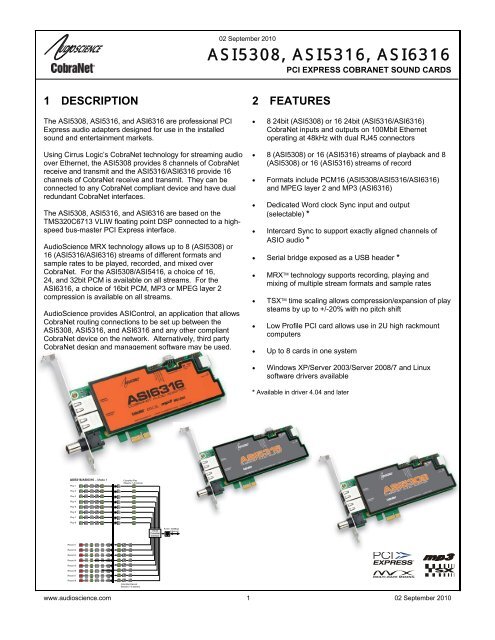
1 DESCRIPTION<br />
The ASI5308, ASI5316, and ASI<strong>6316</strong> are professional PCI<br />
Express audio adapters designed for use in the installed<br />
sound and entertainment markets.<br />
Using Cirrus Logic’s CobraNet technology for streaming audio<br />
over Ethernet, the ASI5308 provides 8 channels of CobraNet<br />
receive and transmit and the ASI5316/ASI<strong>6316</strong> provide 16<br />
channels of CobraNet receive and transmit. They can be<br />
connected to any CobraNet compliant device and have dual<br />
redundant CobraNet interfaces.<br />
The ASI5308, ASI5316, and ASI<strong>6316</strong> are based on the<br />
TMS320C6713 VLIW floating point DSP connected to a highspeed<br />
bus-master PCI Express interface.<br />
AudioScience MRX technology allows up to 8 (ASI5308) or<br />
16 (ASI5316/ASI<strong>6316</strong>) streams of different formats and<br />
sample rates to be played, recorded, and mixed over<br />
CobraNet. For the ASI5308/ASI5416, a choice of 16,<br />
24, and 32bit PCM is available on all streams. For the<br />
ASI<strong>6316</strong>, a choice of 16bit PCM, MP3 or MPEG layer 2<br />
compression is available on all streams.<br />
AudioScience provides ASIControl, an application that allows<br />
CobraNet routing connections to be set up between the<br />
ASI5308, ASI5316, and ASI<strong>6316</strong> and any other compliant<br />
CobraNet device on the network. Alternatively, third party<br />
CobraNet design and management software may be used.<br />
2 FEATURES<br />
• 8 24bit (ASI5308) or 16 24bit (ASI5316/ASI<strong>6316</strong>)<br />
CobraNet inputs and outputs on 100Mbit Ethernet<br />
operating at 48kHz with dual RJ45 connectors<br />
• 8 (ASI5308) or 16 (ASI5316) streams of playback and 8<br />
(ASI5308) or 16 (ASI5316) streams of record<br />
• Formats include PCM16 (ASI5308/ASI5316/ASI<strong>6316</strong>)<br />
and MPEG layer 2 and MP3 (ASI<strong>6316</strong>)<br />
• Dedicated Word clock Sync input and output<br />
(selectable) *<br />
• Intercard Sync to support exactly aligned channels of<br />
ASIO audio *<br />
• Serial bridge exposed as a USB header *<br />
• MRX technology supports recording, playing and<br />
mixing of multiple stream formats and sample rates<br />
• TSX time scaling allows compression/expansion of play<br />
steams by up to +/-20% with no pitch shift<br />
• Low Profile PCI card allows use in 2U high rackmount<br />
computers<br />
• Up to 8 cards in one system<br />
• Windows XP/Server 2003/Server 2008/7 and Linux<br />
software drivers available<br />
* Available in driver 4.04 and later<br />
ASI5316/ASI<strong>6316</strong> – Mode 1<br />
Play 1<br />
CobraNet Play<br />
Streams 1-8 (stereo)<br />
Play 2<br />
Play 3<br />
Play 4<br />
Play 5<br />
Play 6<br />
Play 7<br />
Play 8<br />
16x16<br />
CobraNet<br />
Interface<br />
RJ-45 100Mbps<br />
Ethernet<br />
Record 1<br />
Record 2<br />
Record 3<br />
Record 4<br />
Record 5<br />
Record 6<br />
Record 7<br />
Record 8<br />
CobraNet Record<br />
Streams 1-8 (stereo)<br />
www.audioscience.com 1 02 September 2010
ASI5308, ASI5316, ASI<strong>6316</strong><br />
3 SPECIFICATIONS<br />
COBRANET INPUT/OUTPUT<br />
Type<br />
Connector<br />
Precision<br />
Sample Rate<br />
Latency<br />
Control Protocol<br />
100BaseT Ethernet<br />
RJ-4<br />
16, 20 or 24bit PCM<br />
48kHz<br />
1.33, 2.66 or 5.33ms<br />
SNMP<br />
SIGNAL PROCESSING<br />
DSP<br />
Texas Instruments TMS320C6713@300MHz<br />
Memory<br />
8MB<br />
Audio Formats – ASI5308/ASI5316<br />
8 bit unsigned PCM<br />
16 bit signed PCM<br />
24 bit signed PCM<br />
32 bit signed PCM<br />
32 bit floating point PCM<br />
MRX Playback sample<br />
rates<br />
8 to 96kHz with 1Hz resolution<br />
Audio Formats – ASI<strong>6316</strong><br />
8 bit unsigned PCM<br />
16, 24 bit signed PCM<br />
32 bit floating point PCM<br />
MPEG-1 Layer 2<br />
MPEG-1 Layer 3(MP3) (MPEG Layer-3 audio coding technology licensed from Fraunhofer IIS<br />
and THOMSON multimedia)<br />
MRX Playback sample rates 8 to 96kHz with 1Hz resolution<br />
Record sample rates 8 to 96kHz with 1Hz resolution<br />
SRC THD+N<br />
-110dB<br />
GENERAL<br />
Bus<br />
Dimensions<br />
Weight<br />
Operating Temperature<br />
Power Requirements<br />
X1 PCI Express<br />
PCI form factor – 6.1" x 3.25" x 0.5" (155mm x 82mm x 13mm)<br />
8 oz (227g) max<br />
0C to 70C<br />
+3.3V@1.1A<br />
www.audioscience.com 2 02 August 2010
ASI5308, ASI5316, ASI<strong>6316</strong><br />
4 BLOCK DI<strong>AG</strong>RAMS<br />
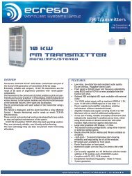
4.1 ASI5316/ASI<strong>6316</strong> Mode-1<br />
ASI5316/ASI<strong>6316</strong> – Mode 1<br />
Play 1<br />
Play 2<br />
Play 3<br />
Play 4<br />
Play 5<br />
Play 6<br />
Play 7<br />
Play 8<br />
CobraNet Play<br />
Streams 1-8 (stereo)<br />
Key:<br />
Play Stream<br />
Sample Rate Converter<br />
Channel Mode<br />
Volume<br />
Meter<br />
Mixer<br />
Record Stream<br />
Voice Operated Switch<br />
Multiplexer<br />
16x16<br />
CobraNet<br />
Interface<br />
RJ-45 100Mbps<br />
Ethernet<br />
Record 1<br />
Record 2<br />
Record 3<br />
Record 4<br />
Record 5<br />
Record 6<br />
Record 7<br />
Record 8<br />
CobraNet Record<br />
Streams 1-8 (stereo)<br />
4.2 ASI5316/<strong>6316</strong> Mono Mode<br />
ASI5316/ASI<strong>6316</strong> - Mono Mode<br />
Play 1<br />
Play 2<br />
Play 3<br />
Play 4<br />
Play 5<br />
Play 6<br />
Play 7<br />
Play 8<br />
Play 9<br />
Play 10<br />
Play 11<br />
Play 12<br />
Play 13<br />
Play 14<br />
Play 15<br />
CobraNet Play<br />
Streams 1-16 (mono)<br />
Play 16<br />
Record 1<br />
CobraNet Record<br />
Streams 1-16 (mono)<br />
16x16<br />
CobraNet<br />
Interface<br />
RJ-45 100Mbps<br />
Ethernet<br />
Record 2<br />
Record 3<br />
Record 4<br />
Record 5<br />
Record 6<br />
Record 7<br />
Record 8<br />
Record 9<br />
Record 10<br />
Record 11<br />
Record 12<br />
Record 13<br />
Record 14<br />
Record 15<br />
Record 16<br />
www.audioscience.com 3 02 August 2010
ASI5308, ASI5316, ASI<strong>6316</strong><br />
5 REVISIONS<br />
Date<br />
Description<br />
29 May 2009 Initial.<br />
30 October 2009 Removed rogue elements from block diagrams.<br />
25 January 2010 Added Clock Source Configurations sections.<br />
16 April 2010<br />
Added Serial Bridge Connections section.<br />
Corrected power requirements and bus type.<br />
21 April 2010 Updates to format and wording.<br />
17 May 2010<br />
Page 1: Added footnote that driver 4.04 or later is needed for noted<br />
functionalities.<br />
12 August 2010 Added ASI5308 and ASI5316.<br />
24 August 2010<br />
Updated CobraNet Audio Channel Mapping section.<br />
Added PCIe errata information.<br />
02 September 2010 Reworded second and third bulleted items under Features.<br />
www.audioscience.com 4 02 August 2010
ASI5308, ASI5316, ASI<strong>6316</strong><br />
6 CONTENTS<br />
1 DESCRIPTION................................................................................................................................................... 1<br />
2 FEATURES ........................................................................................................................................................ 1<br />
3 SPECIFICATIONS ............................................................................................................................................. 2<br />
4 BLOCK DI<strong>AG</strong>RAMS .......................................................................................................................................... 3<br />
4.1 ASI5316/ASI<strong>6316</strong> MODE-1 .........................................................................................................................................3<br />
4.2 ASI5316/<strong>6316</strong> MONO MODE........................................................................................................................................3<br />
5 REVISIONS........................................................................................................................................................ 4<br />
6 CONTENTS........................................................................................................................................................ 5<br />
7 INTRODUCTION................................................................................................................................................ 7<br />
7.1 COBRANET BACKGROUND ...........................................................................................................................................7<br />
7.1.1 CobraNet Routing 8<br />
7.1.2 CobraNet Audio Channel Mapping 9<br />
7.1.3 CobraNet Transmitters 10<br />
7.1.4 CobraNet Receivers 10<br />
7.1.5 CobraNet Sample Rate and Latency 10<br />
7.1.6 CobraNet References 10<br />
8 CONNECTORS................................................................................................................................................ 11<br />
9 CABLES........................................................................................................................................................... 11<br />
10 HARDWARE INSTALLATION......................................................................................................................... 11<br />
10.1 SETTING ADAPTER INDEX – ONE ADAPTER IN THE PC...............................................................................................11<br />
10.2 SETTING ADAPTER INDEX - TWO OR MORE ADAPTERS IN THE PC .............................................................................12<br />
10.3 CLOCK SOURCE CONFIGURATION...............................................................................................................................12<br />
10.3.1 Clock Obtained from the Network and Word Clock Output 13<br />
10.3.2 Clock Obtained from BNC 14<br />
10.3.3 Clock Obtained from Adjacent ASI5308/ASI5316/ASI<strong>6316</strong> 14<br />
10.4 SERIAL BRIDGE CONNECTIONS...................................................................................................................................15<br />
10.5 INTERCARD SYNC .......................................................................................................................................................15<br />
11 SOFTWARE INSTALLATION ......................................................................................................................... 16<br />
11.1 DRIVERS FOR WINDOWS 7/XP/SERVER 2003/SERVER 2008.......................................................................................16<br />
11.1.1 WAVE Driver 16<br />
11.1.2 WDM Driver 16<br />
11.1.3 Combo Driver 16<br />
11.1.4 ASIO 16<br />
11.1.5 Driver Failure 16<br />
11.2 DRIVERS FOR LINUX...................................................................................................................................................17<br />
11.3 APPLICATIONS FOR WINDOWS....................................................................................................................................17<br />
11.3.1 ASIControl 17<br />
11.3.2 ASIMixer 17<br />
12 OPERATION USING ASICONTROL............................................................................................................... 18<br />
12.1 USER INTERFACE........................................................................................................................................................18<br />
12.1.1 Adapter List Window 18<br />
12.1.2 Adapter Topology Window 18<br />
12.1.3 Node Controls Window 19<br />
www.audioscience.com 5 02 August 2010
ASI5308, ASI5316, ASI<strong>6316</strong><br />
12.2 CONTROLS..................................................................................................................................................................19<br />
12.2.1 Adapter Information 19<br />
12.2.2 Adapter Mode 20<br />
12.2.3 Player 20<br />
12.2.4 Recorder 22<br />
12.2.5 Volume 23<br />
12.2.6 Meter 24<br />
12.2.7 Channel_Mode 25<br />
13 ERRATA........................................................................................................................................................... 26<br />
13.1 “BUZZY” AUDIO .........................................................................................................................................................26<br />
13.2 PCIE-TO-PCI BRIDGE.................................................................................................................................................26<br />
www.audioscience.com 6 02 August 2010
ASI5308, ASI5316, ASI<strong>6316</strong><br />
7 INTRODUCTION<br />
The ASI5308/ASI5316/ASI<strong>6316</strong> are PCI audio adapter that support the CobraNet audio interface providing 8<br />
(ASI5308) or 16 (ASI5316/ASI<strong>6316</strong>) channels of CobraNet receive and transmit.<br />
The ASI5308/ASI5316/ASI<strong>6316</strong> feature a powerful Texas Instruments 32bit floating point DSP that allows<br />
sophisticated switching and mixing.<br />
AudioScience provides application software that may be used to set up the ASI5308/ASI5316/ASI<strong>6316</strong>.<br />
ASIControl sets up all internal features of the unit such as levels also allows CobraNet routing connections to be<br />
set up between the ASI5308/ASI5316/ASI<strong>6316</strong> and any other compliant CobraNet device on the network.<br />
7.1 CobraNet Background<br />
CobraNet is a combination of software, hardware and network protocol that allows distribution of many channels<br />
of real-time, high quality digital audio over an Ethernet network. It was developed by Peak Audio in the 1990s and<br />
is now owned by Cirrus Logic. Interoperability between CobraNet devices from different manufacturers is<br />
supported through a standard communications protocol. CobraNet compliant devices are based on a common<br />
silicon or hardware reference design from Cirrus Logic.<br />
The Cirrus Logic website, www.cobranet.info, is dedicated to CobraNet. Wikipedia has a useful introduction to<br />
CobraNet here.<br />
CobraNet delivers audio in standard Ethernet packets over 100Mbit Fast Ethernet. Switches, hubs, media<br />
converters and other gear that operate in compliance with the IEEE 802.3u specification for Fast Ethernet, will<br />
work with CobraNet. CobraNet does not support 10Mbit Ethernet varieties (10BASE-T, Coaxial) due to their<br />
limited bandwidth.<br />
CobraNet operates at the Data Link Layer also referred to as OSI Layer 2 or MAC layer. Because it does not use<br />
the higher IP layer for audio data transport, CobraNet does not suffer from IP latency limitations. In most cases<br />
data communications and CobraNet data can coexist on the same network without QOS issues. All audio is sent<br />
inside a custom Ethernet packet whose header that tells network devices that the packet contains CobraNet audio<br />
rather than plain data. The CobraNet term for an audio packet is "Bundle". A Bundle may contain from one to<br />
eight audio channels, each channel being composed of PCM samples of 16, 20 or 24 bits in length.<br />
www.audioscience.com 7 02 August 2010
ASI5308, ASI5316, ASI<strong>6316</strong><br />
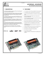
7.1.1 CobraNet Routing<br />
The whole point of network audio is to route digital audio from point A to point B. CobraNet introduces a concept<br />
called a “bundle” to define virtual audio routes from one CobraNet device to another one. A bundle is a logical<br />
collection of up to 8 channels that can be sent from on device to another. Each bundle is assigned a unique<br />
number between 1 and 9999. Bundles form the heart of the CobraNet routing capability.<br />
CobraNet<br />
Device 1<br />
CobraNet<br />
Device 2<br />
Bundle #300<br />
s1,s2,s3,s4,s5,s6,s7,s8<br />
The bundle number 300 is used to describe this collection of channels<br />
coming from Device 1. s1 to s8 represent audio samples. The bundle<br />
shown above consists of 1 to 8 samples of audio each taken from<br />
different channels of Device 1.<br />
Illustration of a CobraNet bundle going between 2 CobraNet devices.<br />
The above figure illustrates a bundle of audio being sent from one CobraNet device to another. Device 1 is<br />
transmitting the CobraNet bundle, while Device 2 is receiving it. In this case, both devices need to be set to<br />
bundle 300 for the audio link to be made. The CobraNet mechanism for transmitting bundles uses “transmitters”.<br />
Similarly, the mechanism for receiving bundles uses receivers. Each CobraNet device has several transmitters<br />
and receivers and so can simultaneously send and receive audio channels using several different bundle<br />
numbers. This capability supports audio links between many different CobraNet devices.<br />
www.audioscience.com 8 02 August 2010
ASI5308, ASI5316, ASI<strong>6316</strong><br />
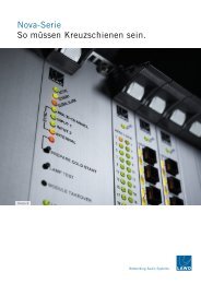
7.1.2 CobraNet Audio Channel Mapping<br />
Before further discussion of CobraNet transmitters and receivers, terminology useful for specifying audio channels<br />
within a bundle needs to be introduced. Somewhat obviously, Cirrus calls these channels ‘audio routing<br />
channels.’<br />
On an ASI5316/ASI<strong>6316</strong>, CobraNet audio routing channels 1-16 map to the ASI5316/<strong>6316</strong>’s line out 1-8 and<br />
CobraNet audio routing channels 33-49 map to the ASI5316/<strong>6316</strong>’s line in channels 1-8. Routing channel 1 maps<br />
to line out 1 left and routing channel 2 maps to line out 1 right and so on, and routing channel 33 maps to line in 1<br />
left and routing channel 34 maps to line in 1 right and so on. (The ASI5308 follows the same logic but with half as<br />
many channels/line ins/line outs.)<br />
When placed in mono mode, CobraNet audio routing channels 1-16 map to the ASI5316/<strong>6316</strong>’s Player channels<br />
1-16 and CobraNet audio routing channels 33-49 map to the ASI5316/<strong>6316</strong>’s Record channels 1-16. (The<br />
ASI5308 follows the same logic but with half as many channels/line ins/line outs.)<br />
CobaraNet_Ch 1<br />
CobaraNet_Ch 2<br />
CobaraNet_Ch 3<br />
CobaraNet_Ch 4<br />
CobaraNet_Ch 5<br />
CobaraNet_Ch 6<br />
CobaraNet_Ch 7<br />
CobaraNet_Ch 8<br />
CobaraNet_Ch 9<br />
CobaraNet_Ch 10<br />
CobaraNet_Ch 11<br />
CobaraNet_Ch 12<br />
CobaraNet_Ch 13<br />
CobaraNet_Ch 14<br />
CobaraNet_Ch 15<br />
CobaraNet_Ch 16<br />
CobaraNet_Ch 33<br />
CobaraNet_Ch 34<br />
CobaraNet_Ch 35<br />
CobaraNet_Ch 36<br />
CobaraNet_Ch 37<br />
CobaraNet_Ch 38<br />
CobaraNet_Ch 39<br />
CobaraNet_Ch 40<br />
CobaraNet_Ch 41<br />
CobaraNet_Ch 42<br />
CobaraNet_Ch 43<br />
CobaraNet_Ch 44<br />
CobaraNet_Ch 45<br />
CobaraNet_Ch 46<br />
CobaraNet_Ch 47<br />
CobaraNet_Ch 48<br />
Mono Mode<br />
line out 1 left<br />
line out 1 right<br />
line out 2 left<br />
line out 2 right<br />
line out 3 left<br />
line out 3 right<br />
line out 4 left<br />
line out 4 right<br />
line out 5 left<br />
line out 5 right<br />
line out 6 left<br />
line out 6 right<br />
line out 7 left<br />
line out 7 right<br />
line out 8 left<br />
line out 8 right<br />
line in 1 left<br />
line in 1 right<br />
line in 2 left<br />
line in 2 right<br />
line in 3 left<br />
line in 3 right<br />
line in 4 left<br />
line in 4 right<br />
line in 5 left<br />
line in 5 right<br />
line in 6 left<br />
line in 6 right<br />
line in 7 left<br />
line in 7 right<br />
line in 8 left<br />
line in 8 right<br />
49-64 unused<br />
Mode-1<br />
0 (silence)<br />
1<br />
2<br />
3<br />
4<br />
5<br />
6<br />
7<br />
8<br />
9<br />
10<br />
11<br />
12<br />
13<br />
14<br />
15<br />
16<br />
17-32 unused<br />
33<br />
34<br />
35<br />
36<br />
37<br />
38<br />
39<br />
40<br />
41<br />
42<br />
43<br />
44<br />
45<br />
46<br />
47<br />
48<br />
49-64 unused<br />
CobraNet audio<br />
channel used in<br />
transmitters and<br />
receivers<br />
txSubMap<br />
txSubMap<br />
txSubMap<br />
txSubMap<br />
rxSubMap<br />
rxSubMap<br />
rxSubMap<br />
rxSubMap<br />
rxSubMap<br />
rxSubMap<br />
rxSubMap<br />
rxSubMap<br />
Tx1<br />
Tx2<br />
Tx3<br />
Tx4<br />
Rx1<br />
Rx2<br />
Rx3<br />
Rx4<br />
Rx5<br />
Rx6<br />
Rx7<br />
Rx8<br />
Transmit bundles are<br />
sent out on Ethernet<br />
Receive bundles are<br />
received from Ethernet<br />
Figure 3. Mapping of inputs and outputs to CobraNet channels (the ASI5308 follows the same logic but<br />
with 8 channels)<br />
www.audioscience.com 9 02 August 2010
ASI5308, ASI5316, ASI<strong>6316</strong><br />
7.1.3 CobraNet Transmitters<br />
A CobraNet transmitter is a logical entity in the CobraNet interface that has the ability to send a bundle of audio<br />
samples on the CobraNet network. CobraNet devices typically have multiple transmitters. The ASI2416, for<br />
example, has 4 transmitters. An incomplete list of transmitter routing variables follows:<br />
• txBundle – this variable specifies the bundle number to transmit. A value of 0 indicates that the transmitter<br />
is disabled.<br />
• txSubMap – a sequence of up to 8 audio routing channel numbers that specify which audio samples<br />
should be placed in the bundle. A value of 0 indicates an unused slot in the bundle.<br />
• txSubFomat – a sequence of format specifiers that define how many bits per sample are placed in the<br />
bundle.<br />
• txSubCount – the number of channels in this bundle.<br />
7.1.4 CobraNet Receivers<br />
A CobraNet receiver is a logical entity in the CobraNet interface that has the ability to receiver a bundle of audio<br />
samples from the CobraNet network. CobraNet devices typically have multiple receivers. The ASI2416, for<br />
example, has 4 receivers. An incomplete list of receiver routing variables follows:<br />
• rxBundle – the number of the bundle to receive. This should be the same a bundle number being<br />
transmitted somewhere else on the network. A value of 0 indicates that the receiver is disabled.<br />
• rxSubMap – a sequence of up to 8 audio routing channel numbers that specify where incoming bundle<br />
samples should be routed.<br />
7.1.5 CobraNet Sample Rate and Latency<br />
The CobraNet sample rate supported by the ASI2416 and ASI6416 is fixed at 48kHz with three latency modes of<br />
5.33ms (default), 2.67ms or 1.33ms.<br />
7.1.6 CobraNet References<br />
This document is not intended to be an expansive guide to CobraNet networking and routing. The ASI2416 and<br />
ASI6416 adhere to the CobraNet standard through the use of off-the-self CobraNet silicon from Cirrus Logic.<br />
More detailed CobraNet information is available from them.<br />
The following links may be helpful:<br />
CobraNet Info: http://www.cobranet.info/en/support/cobranet/<br />
CobraNet Discovery:<br />
http://www.cobranet.info/dispatch/forms/sup/boardreg/breg/BregController.jpf<br />
Audio Routing Primer:<br />
http:// www.cirrus.com/en/pubs/appNote/CobraNet_AudioRoutingPrimer.pdf<br />
Hardware manual and programmer’s reference:<br />
http://www.cobranet.info/en/support/cobranet/developer/tech_data_sheet.html<br />
www.audioscience.com 10 02 August 2010
ASI5308, ASI5316, ASI<strong>6316</strong><br />
8 CONNECTORS<br />
The ASI5308/5316/<strong>6316</strong> uses standard, dual RJ-45 connectors.<br />
9 CABLES<br />
The ASI5308/5316/<strong>6316</strong> is connected to a CobraNet network using a standard Ethernet cable. The Ethernet<br />
cable is not supplied with the ASI5308/5316/<strong>6316</strong>.<br />
10 HARDWARE INSTALLATION<br />
This section explains how to install one or more AudioScience adapters in a computer.<br />
10.1 Setting Adapter Index – One Adapter in the PC<br />
1. Make sure your computer is turned off.<br />
2. PCI adapters should be installed in any empty PCI slot and PCIe adapters should be installed in any x1 (or<br />
greater) PCIe slot.<br />
3. Make sure the adapter jumper is set to adapter index #1, the factory default. For a new card no changes need<br />
to be made. For an AudioScience adapter from another installation, check that it is set to adapter index #1.<br />
Depending on the adapter family, there are different ways of setting the adapter index.<br />
For ASI5000 and ASI6000 families, there is<br />
an adapter jumper that must be set. The left<br />
most position represents adapter index #1.<br />
Adapter Jumper set<br />
to Adapter #1<br />
For ASI5300, ASI6300, ASI8700, and<br />
ASI8900 families, there is a rotary switch.<br />
NOTE: Position 0 (zero) represents adapter<br />
#1, position 1 is adapter #2, etc.<br />
Adapter Index switch<br />
set to Adapter #1<br />
4. Turn on the computer and let it boot. Under Windows, a dialog box will pop up informing you that the<br />
computer has detected a new Multimedia Audio card. Cancel out of this dialog box and proceed to the software<br />
installation section of this datasheet.<br />
www.audioscience.com 11 02 August 2010
ASI5308, ASI5316, ASI<strong>6316</strong><br />
10.2 Setting Adapter Index - Two or More Adapters in the PC<br />
1. Make sure your computer is turned off.<br />
2. PCI adapters should be installed in any empty PCI slots and PCIe adapters should be installed in any x1 (or<br />
greater) PCIe slots. Different adapter types can coexist in the same computer; for example, an ASI6416 and<br />
ASI8921 will work correctly if installed in the same PC. Different adapter types still require unique adapter index<br />
numbers.<br />
3. Each adapter in the PC needs to have its adapter jumper/rotary switch position set to unique numbers. For<br />
example if you are installing two adapters, the first one would be set to adapter index #1 and the second to<br />
adapter index #2.<br />
For ASI5000 and ASI6000 families, the position to the right of index #1, when jumpered, represents adapter index<br />
#2. The next position represents #3, and the rightmost position, when jumpered, represents #4.<br />
For ASI5300, ASI6300, ASI8700, and ASI8900 families, rotate the rotary switch to indicate what position is<br />
required.<br />
4. Turn on the computer and let it boot. Under Windows, a dialog box will pop up informing you that the computer<br />
has detected a new Multimedia Audio card. Cancel out of this dialog box and proceed to the software installation<br />
section of this datasheet.<br />
10.3 Clock Source Configuration<br />
The ASI5308/5316/<strong>6316</strong> can obtain its CobraNet sample clock from the following three sources:<br />
• The CobraNet network (default)*<br />
o Set using ASIControl; see Section 9.1 below<br />
• If using BNC out, need to also jumper WCLK OUTPUT IS BNC on J12<br />
• A word clock input through the ASI5308/5316/<strong>6316</strong>’s BNC connector (ASI5308/5326/<strong>6316</strong> is CobraNet<br />
conductor)<br />
o Set using ASIControl and jumpering WCLK INPUT IS BNC on J12; see Section 9.2 below<br />
• A word clock input from an adjacent ASI5308/5316/<strong>6316</strong><br />
o Set using another ASI5308/5316/<strong>6316</strong> in the same PC and a 10pin ribbon cable, see Section 9.3<br />
below<br />
*The default ASI5308/5316/<strong>6316</strong> clock source configuration is “Network”, which derives the CobraNet clock from<br />
the CobraNet network. This default setting will work correctly for 90% of installation scenarios. In this scenario the<br />
BNC connector can be ignored and there is no need to adjust any of the jumpers on J12. By default, the BNC<br />
connector is configured as an input Word clock with 75ohm termination.<br />
www.audioscience.com 12 02 August 2010
ASI5308, ASI5316, ASI<strong>6316</strong><br />
The following diagram shows the ASI5308/5316/<strong>6316</strong> and its various connectors/jumpers and headers. Most of<br />
the components seen below are hidden by the orange ASI5308/5316/<strong>6316</strong> faceplate; the labeled areas are not.<br />
No connection<br />
J12-4 - WCLK INPUT IS HEADER<br />
J12-3 - WCLK INPUT IS BNC<br />
J12-2 - WCLK OUTPUT IS BNC<br />
J12-1 - BNC 75Ω TERM<br />
J12<br />
ADAPTER<br />
INDEX<br />
1-8<br />
J9<br />
INTERCARD<br />
SYNC IN<br />
J10<br />
INTERCARD<br />
SYNC OUT<br />
USB-B<br />
Primary<br />
CobraNet<br />
Secondary<br />
CobraNet<br />
USB<br />
SERIAL<br />
PORT<br />
BNC<br />
connector<br />
10.3.1 Clock Obtained from the Network and Word Clock Output<br />
This is the default ASI5308/5316/<strong>6316</strong> clock source configuration. The ASI5308/5316/<strong>6316</strong> obtains its clock from<br />
the CobraNet network as a Performer or supplies it to the network as a Conductor. The diagram below shows (in<br />
bold) the clock signal flow. If the BNC is required to output the network clock, jumper the WCLK OUTPUT IS<br />
BNC Jumper on J12.<br />
INTERCARD SYNC<br />
HEADER – IN – J9<br />
To ASI<strong>6316</strong><br />
audio clocking<br />
WCLK INPUT<br />
IS HEADER<br />
J12-4<br />
CobraNet<br />
Network<br />
NETWORK<br />
WORD<br />
CobraNet<br />
clock<br />
generation<br />
INTERCARD SYNC<br />
HEADER – OUT – J10<br />
NETWORK<br />
WORD<br />
BNC 75Ω TERM<br />
J12-1<br />
WCLK OUTPUT<br />
IS BNC<br />
J12-2<br />
WCLK INPUT<br />
IS BNC<br />
J12-3<br />
BNC WORD<br />
CLOCK I/O<br />
www.audioscience.com 13 02 August 2010
ASI5308, ASI5316, ASI<strong>6316</strong><br />
10.3.2 Clock Obtained from BNC<br />
In this mode, the ASI5308/5316/<strong>6316</strong> takes a 48kHz word clock in on the BNC causing the CobraNet interface<br />
and the card to be synchronized. The clock is available on the INTERCARD SYNC HEADER OUT header to be<br />
sent to another ASI5308/5316/<strong>6316</strong> if needed. The ASI5308/5316/<strong>6316</strong> needs to be the CobraNet Conductor or<br />
the BNC clock needs to be synchronized to the CobraNet network clock.<br />
INTERCARD SYNC<br />
HEADER – IN – J9<br />
To ASI<strong>6316</strong><br />
audio clocking<br />
WCLK INPUT<br />
IS HEADER<br />
J12-4<br />
CobraNet<br />
Network<br />
NETWORK<br />
WORD<br />
CobraNet<br />
clock<br />
generation<br />
INTERCARD SYNC<br />
HEADER – OUT – J10<br />
NETWORK<br />
WORD<br />
BNC 75Ω TERM<br />
(if needed)<br />
J12-1<br />
WCLK OUTPUT<br />
IS BNC<br />
J12-2<br />
WCLK INPUT<br />
IS BNC<br />
J12-3<br />
BNC WORD<br />
CLOCK I/O<br />
10.3.3 Clock Obtained from Adjacent ASI5308/ASI5316/ASI<strong>6316</strong><br />
In this mode, one ASI5308/5316/<strong>6316</strong> receives its word clock from an adjacent ASI5308/5316/<strong>6316</strong> using a 10pin<br />
ribbon cable. Attach one end of the 10pin ribbon cable to J9 on one of the ASI5308/5316/<strong>6316</strong>s and attach the<br />
other end of the 10pin ribbon cable to J10 of the other ASI5308/5316/<strong>6316</strong>.<br />
INTERCARD SYNC<br />
HEADER – IN – J9<br />
To ASI<strong>6316</strong><br />
audio clocking<br />
WCLK INPUT<br />
IS HEADER<br />
J12-4<br />
CobraNet<br />
Network<br />
NETWORK<br />
WORD<br />
CobraNet<br />
clock<br />
generation<br />
INTERCARD SYNC<br />
HEADER – OUT – J10<br />
NETWORK<br />
WORD<br />
J9<br />
BNC 75Ω TERM<br />
(if needed)<br />
J12-1<br />
WCLK OUTPUT<br />
IS BNC<br />
J12-2<br />
WCLK INPUT<br />
IS BNC<br />
J12-3<br />
J10<br />
BNC WORD<br />
CLOCK I/O<br />
www.audioscience.com 14 02 August 2010
ASI5308, ASI5316, ASI<strong>6316</strong><br />
10.4 Serial Bridge Connections<br />
Most motherboards have internal USB headers. The ASI5308/5316/<strong>6316</strong>’s 5pin header at J8 can be connected<br />
to the motherboard’s USB header using a cable such as USB-F5RF5R from http://www.performance-pcs.com.<br />
Connection should only be made to J4 or J8 as they both interface to the same USB bus.<br />
CobraNet<br />
Network<br />
CobraNet<br />
Serial<br />
Bridge<br />
Data<br />
UART<br />
Serial to USB<br />
FT232R<br />
USB 2.0<br />
J4<br />
USB-B<br />
J8<br />
VBUS<br />
D-<br />
D+<br />
5-pin<br />
header<br />
N<br />
GND<br />
The motherboard should have a USB header with the following pinout:<br />
Motherboard Internal USB Header Pinouts<br />
+5V 1 2 +5V<br />
D- 3 4 D-<br />
D+ 5 6 D+<br />
GND 7 8 GND<br />
Key 9 10 NC<br />
10.5 Intercard Sync<br />
Intercard Sync across multiple ASI5308/5316/<strong>6316</strong>s supports exactly aligned channels of ASIO audio. 10pin<br />
ribbon cables are used to connect up to 8 ASI5308/5316/<strong>6316</strong>s for up to 128 channels of ASIO audio. Attach the<br />
cables with the PC powered down.<br />
1. Connect the ASI5308/5316/<strong>6316</strong>s. This is done by attaching one end of the 10pin ribbon cable to J9 on one of<br />
the ASI5308/5316/<strong>6316</strong>s and attaching the other end of the 10pin ribbon cable to J10 of the other<br />
ASI5308/5316/<strong>6316</strong> as shown in the image below. If connecting more than 2 ASI5308/5316/<strong>6316</strong>s together,<br />
daisy chain J9 to J10 on each ASI5308/5316/<strong>6316</strong> down the line.<br />
2. Aggregate all of the ASI5308/5316/<strong>6316</strong>s being used by<br />
placing a checkmark next to each ASI5308/5316/<strong>6316</strong> in the<br />
AsiAsio Control Panel’s Adapter and Sample Type Selection<br />
tab.<br />
J9<br />
The AsiAsio Control Panel can be found by going StartAll<br />
ProgramsAudioScienceAsiAsio Control Panel. In most<br />
ASIO applications, this Control Panel can also be accessed<br />
within the configuration area of the application.<br />
J10<br />
www.audioscience.com 15 02 August 2010
ASI5308, ASI5316, ASI<strong>6316</strong><br />
11 SOFTWARE INSTALLATION<br />
AudioScience makes audio adapters and drivers for various operating systems. Enhancements to an adapter’s<br />
utility come from the integrators software that uses the audio driver to implement sophisticated audio playback<br />
and recording functions.<br />
11.1 Drivers for Windows 7/XP/Server 2003/Server 2008<br />
The first step is what type of driver is needed for the adapter. There are two types of drivers for Windows: The<br />
WAVE driver and the WDM driver. Typically this will be decided by the application used with the AudioScience<br />
adapter. For any application that uses DirectSound, use the WDM driver.<br />
Driver 3.10 and later present the user with three install options during installation:<br />
• Install Standard PCI/PCIe Driver.<br />
• Install Standard + Network Audio Driver.<br />
• Remove all driver components<br />
Traditional installs should select the first of these options. Users of AudioScience CobraNet products should<br />
select the second option with the “+Network Audio Driver.” in the text.<br />
11.1.1 WAVE Driver<br />
Download the file named ASIWAVE_xxxxxx.EXE from www.audioscience.com and run it (_xxxxxx is the version<br />
number). After the EXE has run, reboot the computer and the audio adapter will be operational. If the cover is off<br />
the computer, one can see one or two blinking LEDs on top of the card indicating its DSP is running and<br />
communicating with the driver. Verify that the adapter is running using ASIControl (see ASIControl section in this<br />
document).<br />
11.1.2 WDM Driver<br />
Download the file named ASIWDM_xxxxxx.EXE from www.audioscience.com and run it (_xxxxxx is the version<br />
number). After the EXE has run, reboot the computer and the audio adapter will be operational. If the cover is off<br />
the computer, one can see one or two blinking LEDs on top of the card indicating its DSP is running and<br />
communicating with the driver.<br />
Verify that the adapter is running using ASIControl (see ASIControl section in this document).<br />
11.1.3 Combo Driver<br />
The Combo driver presents both Wave and WDM devices to the user. Download the file named<br />
ASICOMBOV_xxxxxx.EXE from www.audioscience.com and run it (_xxxxxx is the version number). After the EXE<br />
has run, reboot your computer and the audio adapter will be operational. If the cover is off the computer, one can<br />
see one or two blinking LEDs on top of the card indicating its DSP is running and communicating with the driver.<br />
Verify that the adapter is running using ASIControl (see ASIControl section in this document).<br />
11.1.4 ASIO<br />
All AudioScience drivers also install an ASIO driver interface. It is installed by default.<br />
11.1.5 Driver Failure<br />
In the event that an adapter’s driver fails to load correctly, the OS’s event viewer should be checked. The event<br />
log is viewed as follows:<br />
XP: The system event log is accessed from \Start\Control Panel\Administrative Tools\Event Viewer. The System<br />
view should be selected.<br />
7: The system event log is accessed from \Start\Control Panel\System and Maintenance\Administrative<br />
Tools\Event Viewer. The Windows Logs\System view should be selected.<br />
If two or more adapters are installed in the same system, the first thing to check is that the adapters were<br />
assigned unique adapter numbers. If issues persist, please email support@audioscience.com.<br />
www.audioscience.com 16 02 August 2010
ASI5308, ASI5316, ASI<strong>6316</strong><br />
11.2 Drivers for Linux<br />
The latest Linux driver can be downloaded from the AudioScience website – www.audioscience.com.<br />
11.3 Applications for Windows<br />
AudioScience provides two application for adapter set-up and configuration: ASIControl and ASIMixer.<br />
11.3.1 ASIControl<br />
All Windows drivers install an AudioScience application called ASIControl that can be used to setup and verify<br />
functionality of adapters. ASIControl provides a common interface for users across all driver types.<br />
The following list of controls are uniquely supported in ASIControl (as opposed to ASIMixer):<br />
ASI8700 tuner pre-emphasis<br />
ASI8900 tuner RBDS<br />
ASI8900 tuner FM stereo indication<br />
ASI8914 HD Radio PSD field<br />
ASI8914 HD Radio Digital status field<br />
ASI8914 HD Radio Digital program number selection<br />
From the Windows Start menu, navigate to StartProgramsAudioScience and run the ASIControl program.<br />
When started, ASIControl will look something like the following:<br />
11.3.2 ASIMixer<br />
ASIMixer is specific to the Wave and Combo drivers and is available from the AudioScience website. It uses the<br />
Wave/Mixer interface to control AudioScience adapters. Users of driver version 3.10 and later are encouraged to<br />
use ASIControl for manipulating adapter controls. See the list of controls in the previous section that that are only<br />
available in ASIControl.<br />
www.audioscience.com 17 02 August 2010
ASI5308, ASI5316, ASI<strong>6316</strong><br />
12 OPERATION USING ASICONTROL<br />
Using ASIControl, the ASI5308/5316/<strong>6316</strong> will look similar to the following:<br />
Adapter<br />
List<br />
Window<br />
Node<br />
Controls<br />
Window<br />
Adapter<br />
Topology<br />
Window<br />
12.1 User Interface<br />
ASIControl consists of three main windows: the adapter list in the top portion of the window, the adapter topology<br />
view on the left hand side and the node control list on the right hand side.<br />
12.1.1 Adapter List Window<br />
The top portion of ASIControl shows a list of all the adapters that the application has found. By default, only bus<br />
based (i.e. PCI and/or PCI Express) adapters will be shown. If network support has been installed with the driver<br />
then AudioScience and other 3rd party CobraNet devices will be shown.<br />
Adapters are listed in order of adapter index. For bus-based adapters, this is determined by the adapter index<br />
jumper on the card. For AudioScience CobraNet devices such as the ASI2416 this is calculated from the units<br />
MAC address. 3rd party CobraNet devices are listed last as they have no AudioScience index.<br />
12.1.2 Adapter Topology Window<br />
The left hand side of ASIControl contains the topology view of the adapter. It is essentially a block diagram of the<br />
device showing the available physical inputs and outputs on the right hand side. On the left hand side, bus based<br />
adapters show player and recorder streams, while CobraNet adapters show their network connections.<br />
www.audioscience.com 18 02 August 2010
ASI5308, ASI5316, ASI<strong>6316</strong><br />
Each of these inputs and outputs is referred to as a Node and each Node contains one or more Controls on it.<br />
The topology shows each Control as a small square icon. A non-exhaustive list of nodes follows:<br />
Line In<br />
Line Out<br />
AES/EBU In<br />
AES/EBU Out<br />
Player<br />
Recorder<br />
Tuner<br />
Clock Source In<br />
CobraNet In<br />
CobraNet Out<br />
Hovering the mouse over a particular node will highlight it. Clicking on a node will bring up the controls resident<br />
on that node in the right hand control list.<br />
There is an adapter node in the top left corner. Clicking on this will show adapter specific controls and properties<br />
on the right hand side.<br />
12.1.3 Node Controls Window<br />
The right hand side of ASIControl shows the controls associated with the selected node on the topology view.<br />
The controls are arranged, from top to bottom, in order of audio signal flow, i.e. the audio signal can be viewed as<br />
entering the node at the top control and leaving at the bottom control.<br />
12.2 Controls<br />
The following subsections list all of the controls for the ASI5308/5316/<strong>6316</strong>. Each control’s interface as it appears<br />
in ASIControl is detailed and where applicable, the API to use the control is described.<br />
12.2.1 Adapter Information<br />
This control displays information about the installed adapter or ASI2416.<br />
12.2.1.1 Interface<br />
Figure 1. Adapter information seen in right side of ASIControl.<br />
Serial Number:<br />
The serial number is displayed here.<br />
Hardware Revision:<br />
This lists the hardware revision.<br />
DSP Software Version:<br />
The DSP software version is displayed; usually the same as the driver version installed.<br />
DSP Utilization:<br />
This shows the loading of the adapter’s DSP in percent.<br />
Note: Utilization should be kept below 90%.<br />
www.audioscience.com 19 02 August 2010
ASI5308, ASI5316, ASI<strong>6316</strong><br />
12.2.2 Adapter Mode<br />
The Adapter_Mode control changes the number of players/recorders/lineouts that an adapter has. Not all sample<br />
rates/formats are supported; changing the mode of the adapter allows for best functionality with certain sample<br />
rates/formats. Not all adapters have the same modes, and not all adapters have modes. Please see datasheets<br />
on specific adapters, available at www.audioscience.com, to learn more.<br />
12.2.2.1 Interface<br />
Figure 2. Adapter_Mode in ASIControl.<br />
Selecting the appropriate mode from the list using the dropdown arrow changes the Adapter_Mode setting. A<br />
reboot is necessary after changing adapter mode. The mode setting is saved to the adapter’s EEPROM.<br />
The ASI5308/5316/<strong>6316</strong> supports four adapter modes: 16-Play, Mode 1, Mode 2, and Mono (Mono mode added<br />
in driver 3.14.00 and later).<br />
12.2.2.2 16-Play<br />
This mode supports 16 Play streams and 16 Record streams with restricted mixing capabilities (with driver<br />
3.14.00 and later, there are no mixing restrictions). It is recommended that play and record formats be<br />
constrained to 48 kHz mono PCM if all 16 devices are to be used.<br />
12.2.2.3 Mode 1 (default) – Standard Mixing<br />
This mode supports 8 Play streams and 8 Record streams with full mixing capabilities.<br />
12.2.2.4 Mode 2 – Minimal Mixing<br />
This mode supports playback from each Play device to a single LineOut and has no LineIn to LineOut mixing<br />
capabilities. This conserves DSP MIPS. Mode 2 supports recording stereo MP2 at 48 kHz on all 8 Record<br />
streams.<br />
12.2.2.5 Mono<br />
This mode supports 16 mono Play streams and 16 mono Record streams with full mixing capabilities. Mono<br />
mode supports PCM only. Mono mode supports mapping a single Play device to a mono CobraNet channel,<br />
allowing independent audio output on each channel.<br />
12.2.3 Player<br />
The Player control supports playback of an audio file from the computer’s hard drive.<br />
12.2.3.1 Interface<br />
Figure 3. A player in ASIControl.<br />
www.audioscience.com 20 02 August 2010
ASI5308, ASI5316, ASI<strong>6316</strong><br />
The first line of static text contains the selected playback file. Below the filename is the file information; playback<br />
time and playback bytes, the timescale select options, the player control buttons and the file repeat option.<br />
12.2.3.2 How To Play a File<br />
The first step in playing a file is to select the file to play. Use the file icon button to navigate to the desired file.<br />
After opening the file, the complete filename, including the path, will appear immediately to the left of the file open<br />
icon. At this point the file information is also filled in so that it contains the following fields: “Channels”, “Rate”,<br />
“Format”, and “Bit Rate”. Most of there are self-explanatory. The “Rate” refers to the sample rate of the audio<br />
recorded in the file. The “Bit Rate” applies only to MPEG compression and is set to 0 for all other formats.<br />
At this point the percentage time scaling without pitch shift can be set if desired. The default of 0 indicates that<br />
time scaling is disabled. The valid range of settings is +/- 20 percent.<br />
The “Repeat” check box indicates whether the file should be played again after playback has completed. It can be<br />
set either before playback has begun, or while playback is underway. The file is now ready to be played. To start<br />
playback press the play button. At this point the “Time” and “Bytes” fields report playback time and the number<br />
of bytes of the file that have been played. Once playback has started, the stop and pause buttons can be used<br />
to stop or pause the playback.<br />
12.2.3.3 Using embedded sine wave generator<br />
Manually typing in a filename of “~” and pressing play will cause a full-scale 1 kHz sine wave to be played at 48<br />
kHz. The format of the filename string is: "~w, c,f,a,m,s,t".<br />
w = waveform = SINE (default=SINE)<br />
c = channels = 1..8 (default = 2)<br />
f = frequency = 1000 for 1kHz (default=1000)<br />
a = amplitude = -1 for -1dBFs (default=0dBFS, i.e. full scale)<br />
m = channel mask = 10 for left only, 01 for right only, 11 for stereo etc (default=1 for all channels)<br />
t = sample type = (PCM8,PCM16,PCM24,PCM32,FLOAT32), (default=FLOAT32)<br />
s = sample rate = positive integer (default=48000) [validity depends on adapter]<br />
Defaults can be used if the complete string is not specified, i.e.<br />
"~" becomes "~wSINE,c2,f1000,a0,m11,s48000,tFLOAT32"<br />
Any subset of the options may be specified, the remaining options will be set to the defaults. e.g. "~f500" = 500Hz<br />
stereo sine wave at 0dBFS, 48kHz sample rate.<br />
12.2.3.4 Developer<br />
12.2.3.4.1 Windows APIs<br />
Wave – waveOutOpen(), waveOutWrite(), waveOutClose() etc.<br />
HPI – Output stream functions documented here.<br />
ASX – ASX Player control functions documented here.<br />
DirectSound – TBD.<br />
12.2.3.4.2 Linux APIs<br />
HPI – TBD.<br />
www.audioscience.com 21 02 August 2010
ASI5308, ASI5316, ASI<strong>6316</strong><br />
12.2.4 Recorder<br />
The Recorder control supports recording of an audio file.<br />
12.2.4.1 Interface<br />
Figure 4. A recorder in ASIControl.<br />
The first line of text contains the name given to the recorded file along with the location where it is to be saved.<br />
Below the filename is the file information, the record time and record bytes, the recorder control buttons and the<br />
file Append option.<br />
12.2.4.2 How To Record a File<br />
The first step in recording a file is to have audio coming into the adapter. This can be from a line-in or from one of<br />
the players in ASIControl. See appropriate sections in this datasheet to accomplish this. Next, the new file needs<br />
a name and place to be saved, or an existing audio file can be selected to be overwritten or appended to. Use the<br />
file icon button to navigate to the location to create the file and to give it a name, or to open a previously recorded<br />
file to overwrite or append to it. Next, from the dropdown arrows, select the number of “Channels”, the “Sample<br />
Rate”, the “Format”, and the “Bitrate” that the file should be recorded in.<br />
Check the Append checkbox to save the audio to the end of an already existing file.<br />
The file is now ready to be recorded. To start recording, press the record button. At this point the “Time’ and<br />
“Bytes’ fields report record time and the number of bytes of the file that have been recorded.<br />
Once recording has started, the stop and pause buttons can be used to stop or pause the playback.<br />
Developer<br />
Windows APIs<br />
Wave – use waveInOpen(), waveInStart() etc.<br />
HPI – use HPI_InStreamxxx() functions.<br />
ASX – use ASX_Recorder_xxx() functions.<br />
DirectSound – TBD.<br />
Linux APIs<br />
HPI – use HPI_InStreamxxx() functions.<br />
ASX – use ASX_Recorder_xxx() functions.<br />
ALSA – TBD<br />
www.audioscience.com 22 02 August 2010
ASI5308, ASI5316, ASI<strong>6316</strong><br />
12.2.5 Volume<br />
The Volume control allows the audio signal’s gain to be altered in the range of –100 to +20dB.<br />
12.2.5.1 Interface<br />
Figure 5. A Volume of a Player in ASIControl.<br />
Left and Right display boxes:<br />
Displays the gain settings that the slider bars are set to.<br />
Slider Bars:<br />
Click on the bar with the mouse and drag to desired gain. Once the bars are selected, the left and right arrow<br />
keys can also be used to change the settings.<br />
Lock:<br />
When checked, locks the left and right channels to the same gain value. When unchecked, allows the left and<br />
right channels to have independent gains.<br />
Autofade:<br />
When pressed, automatically fades the volume to the opposite end of the scale.<br />
12.2.5.2 Developer<br />
12.2.5.2.1 Windows APIs<br />
Wave/Mixer – MIXERCONTROL_CONTROLTYPE_VOLUME<br />
This is a Windows standard volume control. Settings are in the range of 0 to 65535, where 0 completely mutes<br />
the output and 65535 is the maximum volume.<br />
HPI – HPI_Volume APIs.<br />
ASX – ASX_Volume APIs.<br />
DirectSound – TBD.<br />
12.2.5.2.2 Linux APIs<br />
HPI –HPI_Volume APIs.<br />
ASX –ASX_Volume APIs.<br />
ALSA – TBD.<br />
www.audioscience.com 23 02 August 2010
ASI5308, ASI5316, ASI<strong>6316</strong><br />
12.2.6 Meter<br />
Meters in ASIControl are located on audio nodes and display the audio level as the audio signal passes through<br />
the node. Most AudioScience devices return both RMS and peak level readings and ASIControl displays both<br />
simultaneously.<br />
12.2.6.1 Interface<br />
Figure 6. A stereo peak meter display. The RMS is the green bar and the peak is the yellow bar.<br />
To the right of the peak meter is the absolute readings in dBFS. These can be useful when testing input tones of a<br />
specific known level.<br />
The ASI2416 has mono (single channel) peak meter, so only a single bar is displayed in that instance.<br />
12.2.6.2 Developer<br />
12.2.6.2.1 Windows APIs<br />
Wave/Mixer – Meters are read using mixerGetControlDetails() on a control of type signed and with type “Peak”<br />
the name “Peak Meter”. A minimum value is 0 and maximum is 32767. The interface returns the peak readings<br />
only, not the RSM level. It confirms to expected Windows functionality.<br />
HPI – Meters are read using the HPI_Meterxxx() API.<br />
ASX – Meters are read using the ASX_Meter_xxx() API.<br />
DirectSound – TBD.<br />
12.2.6.2.2 Linux APIs<br />
HPI – Meters are read using the HPI_Meterxxx() API.<br />
ASX – Meters are read using the ASX_Meter_xxx() API.<br />
ALSA – TBD.<br />
www.audioscience.com 24 02 August 2010
ASI5308, ASI5316, ASI<strong>6316</strong><br />
12.2.7 Channel_Mode<br />
The channel mode is a mechanism for handling mono to stereo conversions and directing the output to either left<br />
or right channels, as well as outputting left to stereo and right to stereo.<br />
12.2.7.1 Interface<br />
Figure 8. ASIControl view of a player’s channel mode control.<br />
Default playback of either mono or stereo files causes audio to be output from the player on both the left and right<br />
audio channels. The channel mode control can allow the audio to be directed to either the left only or the right<br />
only. Select a channel mode setting from the dropdown list.<br />
Valid settings are:<br />
Normal – left channel out left channel, right channel out right channel<br />
Left<br />
Right<br />
Swap – left channel out right channel and right channel out left channel<br />
Left<br />
Right<br />
Left_to_stereo – left channel out to both left and right channels<br />
Left<br />
Right<br />
Right_to_stereo – right channel out to both left and right channels<br />
Left<br />
Right<br />
Left<br />
Right<br />
Left<br />
Right<br />
Stereo_to_left – left and right channels out to left channel<br />
Left<br />
Right<br />
+<br />
Left<br />
Right<br />
Left<br />
Right<br />
Stereo_to_right – left and right channels out to right channel<br />
Left<br />
Right +<br />
Left<br />
Right<br />
Left<br />
Right<br />
The Stereo_to_left and Stereo_to_right operations perform a sum of the left and right channels and then divides<br />
the result by 2.<br />
www.audioscience.com 25 02 September 2010
ASI5308, ASI5316, ASI<strong>6316</strong><br />
13 ERRATA<br />
13.1 “Buzzy” audio<br />
If “buzzy” audio is heard from an ASI5308/5316/<strong>6316</strong>, the following may fix it:<br />
- (If needed, save current ASI5308/5316/<strong>6316</strong> settings using ASIControl by going to menu item<br />
AdapterSave Configuration.)<br />
- Open ASIControl and in the top pane right click on the ASI5308/5316/<strong>6316</strong> to select Configure<br />
CobraNet. If Persistence is set to on, change it to off.<br />
- Close ASIControl and restart the machine.<br />
13.2 PCIe-to-PCI Bridge<br />
This errata arises due to the poor audio playback performance of the XIO2000 PCIe-to-PCI bridge used<br />
on certain revisions (see below) of AudioScience PCIe audio adapters. The symptom is intermittent audio<br />
breakup when playing many channels of 32-bit PCM audio.<br />
This errata applies to the following PCIe adapters having more than 6 streams of stereo 32-bit<br />
PCM playback active at once:<br />
• ASI<strong>6316</strong> Rev D and earlier<br />
• ASI5316 Rev D and earlier<br />
The workaround is to restrict playback of many audio channels to 16-bit PCM audio format when using<br />
the adapters listed above.<br />
The issue has been resolved in later revisions of the adapters:<br />
• ASI<strong>6316</strong> Rev E and later<br />
• ASI5316 Rev E and later<br />
<br />
www.audioscience.com 26 02 August 2010