Stage Color User Manual (Rev. June 2005) - Elation Professional
Stage Color User Manual (Rev. June 2005) - Elation Professional
Stage Color User Manual (Rev. June 2005) - Elation Professional

You also want an ePaper? Increase the reach of your titles
YUMPU automatically turns print PDFs into web optimized ePapers that Google loves.
<strong>Stage</strong> <strong>Color</strong><br />
Introduction<br />
<strong>Rev</strong>ised 6/05<br />
STAGE COLOR<br />
<strong>User</strong> Instructions<br />
<strong>Elation</strong> <strong>Professional</strong>®<br />
4295 Charter Street<br />
Los Angeles CA 90058<br />
www.elationlighting.com<br />
Introduction: Thank you for purchasing the <strong>Elation</strong> <strong>Professional</strong>®<br />
<strong>Stage</strong> <strong>Color</strong>. To optimize the performance of this product, please<br />
read these operating instructions carefully to familiarize yourself with<br />
the basic operations of this unit. The <strong>Stage</strong> <strong>Color</strong> is a high output,<br />
color mixing Par64 Can, designed for stage and theatrical venues.<br />
Unpacking: Every <strong>Stage</strong> <strong>Color</strong> has been thoroughly tested and has<br />
been shipped in perfect operating condition. Carefully check the shipping<br />
carton for damage that may have occurred during shipping. If the<br />
carton appears to be damaged, carefully inspect your fixture for any<br />
damage and be sure all equipment necessary to operate the unit has<br />
arrived intact. In the event damage has been found or parts are missing,<br />
contact technical support for further instructions. Do not return the<br />
unit to your dealer without contacting technical support first<br />
Customer Support: <strong>Elation</strong> <strong>Professional</strong>® provides a customer support<br />
line, to provide set up help and to answer any question should you<br />
encounter problems during your set up or initial operation. You may<br />
also visit us on the web at www.elationlighting.com for any comments<br />
or suggestions. Service Hours are Monday through Friday 9:00 a.m. to<br />
5:00 p.m. Pacific Standard Time.<br />
Voice: (323) 582-3322<br />
Fax: (323) 582-3108<br />
E-mail: support@elationlighting.com<br />
Warning! To prevent or reduce the risk of electrical shock or fire, do<br />
not expose this unit to rain or moisture.<br />
Caution! There are no user serviceable parts inside this unit. Do not<br />
attempt any repairs yourself, doing so will void your manufactures warranty.<br />
In the unlikely event your unit may require service please contact<br />
<strong>Elation</strong> <strong>Professional</strong>.<br />
Safety Issues: This unit may blow a fuse if the maximum allotted<br />
channel load of 6 amps is reached. If any of the fuses need replacement,<br />
always replace the fuse with the same exact type that was<br />
removed, unless otherwise instructed by an authorized <strong>Elation</strong> <strong>Professional</strong>®<br />
service technician. Use of a different type fuse from that which<br />
is recommended may cause fire or electric shock and will void the<br />
manufactures warranty.<br />
©<strong>Elation</strong> <strong>Professional</strong>® - www.elationlighting.com - <strong>Stage</strong> <strong>Color</strong> Instruction <strong>Manual</strong> Page 2
<strong>Stage</strong> <strong>Color</strong><br />
<strong>Stage</strong> <strong>Color</strong><br />
• R. G. B. <strong>Color</strong> Mixing<br />
• Built-in 3 Channel Electronic Dimmer<br />
• 1800 Watts Maximum Output<br />
• 9 Preset Chase Programs Built-in<br />
• Chase Speed Adjustment<br />
• Fade Time Adjustment<br />
• 3 Operating Modes:<br />
Mode 1: RGB<br />
Mode 2: C&B,<br />
Mode 3: <strong>Color</strong> Scroll<br />
• 3 x ZB-HX600 120v - 575w - 3200k - 300hrs<br />
• Optional Lamps:<br />
ZB-HX601 120v - 575w - 3050k - 1500hrs<br />
ZB-HX400 120v - 400w - 3200k - 300hrs<br />
ZB-HX401 120v - 400w - 3040k - 1500hrs<br />
• Optional Lens<br />
Narrow 10˚ Lens<br />
Wide 16 x 30˚ Lens<br />
Product Registration<br />
The <strong>Stage</strong> <strong>Color</strong> carries a two year limited warranty. Please fill out<br />
the enclosed warranty card to validate your purchase. All returned<br />
service items whether under warranty or not, must be freight prepaid<br />
and accompany a return authorization (R.A.) number. The R.A.<br />
number must be clearly written on the outside of the return package.<br />
A brief description of the problem as well as the R.A. number should<br />
also be written down on a piece of paper included in the shipping<br />
carton. If the unit is under warranty, you must provide a copy of your<br />
proof of purchase invoice. You may obtain a R.A. number by contacting<br />
our customer support team on our customer support number. All<br />
packages returned to the service department not displaying a R.A.<br />
number on the outside of the package will be returned to the shipper.<br />
Features<br />
<strong>Stage</strong> <strong>Color</strong><br />
Safety Precautions<br />
• This unit may blow a fuse if the maximum allotted load of 6 amps is<br />
reached. If the fuse needs replacement, always replace the fuse<br />
with same exact type that was remove. Use of a different type fuse<br />
from that which is recommended may cause fire or electric shock<br />
and will void the manufactures warranty<br />
• To reduce the risk of electrical shock or fire, do not expose this unit<br />
rain or moisture<br />
• Do not spill water or other liquids into or on to your unit<br />
• Be sure that the local power outlet match that of the required voltage<br />
for your unit<br />
• Do not attempt to operate this unit if the power cord has been<br />
frayed or broken<br />
• Do not attempt to remove or break off the ground prong from the<br />
electrical cord. This prong is used to reduce the risk of electrical<br />
shock and fire in case of an internal short<br />
• Disconnect from main power before making any type of connection<br />
• Do not remove the cover under any conditions. There are no user<br />
serviceable parts inside<br />
• Never operate this unit when it’s cover is removed<br />
• Never plug this unit in to a dimmer pack<br />
• Always be sure to mount this unit in an area that will allow proper<br />
ventilation. Allow about 6” (15cm) between this device and a wall<br />
• Do not attempt to operate this unit, if it becomes damaged<br />
• This unit is intended for indoor use only, use of this product out<br />
doors voids all warranties<br />
• During long periods of non-use, disconnect the unit’s main power<br />
• Always mount this unit in safe and stable matter<br />
• Power cords should be routed so they are not likely to be walked<br />
on, pinched by items placed upon or against them.<br />
• Cleaning -The fixture should be cleaned only as recommended by<br />
the manufacturer. See page 14 for cleaning details<br />
• Heat -The appliance should be situated away from heat sources<br />
such as radiators, heat registers, stoves, or other appliances<br />
(including amplifiers) that produce heat.<br />
• The fixture should be serviced by qualified service personnel when:<br />
A. The power-supply cord or the plug has been damaged.<br />
B. Objects have fallen, or liquid has been spilled into the unit.<br />
C. The unit has been exposed to rain or water.<br />
©<strong>Elation</strong> <strong>Professional</strong>® www.elationlighting.com <strong>Stage</strong> <strong>Color</strong> Instruction <strong>Manual</strong> Page 3 ©<strong>Elation</strong> <strong>Professional</strong>® www.elationlighting.com <strong>Stage</strong> <strong>Color</strong> Instruction <strong>Manual</strong> Page 4
<strong>Stage</strong> <strong>Color</strong><br />
<strong>Stage</strong> <strong>Color</strong><br />
Description<br />
The <strong>Stage</strong> <strong>Color</strong>. is a 3 channel DMX, color mixing par can. With the<br />
use of a DMX controller, this unit can create up to 16,000,000 colors.<br />
The unit also includes a built-in dimmer that allows for full dimming<br />
functions and eliminates the need of an external dimmer pack. For<br />
added convenience the unit comes with a 4-digit LED display for function<br />
settings and easy DMX addressing.<br />
<strong>Stage</strong> <strong>Color</strong><br />
General Instructions<br />
To optimize the performance of this product, please read these<br />
operating instructions carefully to familiarize yourself with the basic<br />
operations of this unit. These instructions contain important safety<br />
information regarding the use and maintenance of this unit. Please<br />
keep this manual with the unit, for future reference.<br />
Set Up<br />
Power Supply: Before plugging your unit in, be sure the source voltage<br />
in your area matches the required voltage for your <strong>Elation</strong> <strong>Professional</strong>®<br />
<strong>Stage</strong> <strong>Color</strong>. The <strong>Stage</strong> <strong>Color</strong> is available in a 120v and<br />
220v version. Because line voltage may vary from venue to venue, you<br />
should be sure your unit voltage matches the wall outlet voltage before<br />
attempting to power up your fixture.<br />
DMX-512: DMX is short for Digital Multiplex. This is a universal protocol<br />
used as a form of communication between intelligent fixtures<br />
and controllers. A DMX controller sends DMX data instructions from<br />
the controller to the fixture. DMX data is sent as serial data that travels<br />
from fixture to fixture via the DATA “IN” and DATA “OUT” XLR terminals<br />
located on all DMX fixtures (most controllers only have a DATA<br />
“OUT” terminal).<br />
DMX Linking: DMX is a language allowing all makes and models of<br />
different manufactures to be linked together and operate from a single<br />
controller, as long as all fixtures and the controller are DMX compliant.<br />
To ensure proper DMX data transmission, when using several<br />
DMX fixtures try to use the shortest cable path possible. The order<br />
in which fixtures are connected in a DMX line does not influence the<br />
DMX addressing. For example; a fixture assigned a DMX address of 1<br />
may be placed anywhere in a DMX line, at the beginning, at the end,<br />
SOUND<br />
<strong>Stage</strong> <strong>Color</strong><br />
Set Up<br />
or anywhere in the middle. When a fixture is assigned a DMX address<br />
of 1, the DMX controller knows to send DATA assigned to address 1<br />
to that unit, no matter where it is located in the DMX chain.<br />
Data Cable (DMX Cable) Requirements (For DMX and Master/<br />
Slave Operation): The <strong>Stage</strong> <strong>Color</strong> can be controlled via DMX-512<br />
protocol. The <strong>Elation</strong> <strong>Professional</strong>® <strong>Stage</strong> <strong>Color</strong> can use up to three<br />
channels of DMX. The DMX address is set on the rear panel of the<br />
<strong>Stage</strong> <strong>Color</strong>. Your unit and your DMX controller<br />
require a standard 3-pin XLR connector for<br />
data input and data output (Figure 1). If you are<br />
REMOTE INPUT OUTPUT<br />
REMOTE INPUT OUTPUT<br />
making your own CONTROL cables, be sure to SOUND use standard CONTROL<br />
INPUT<br />
INPUT<br />
two conductor shielded cable (This cable may<br />
be purchased at almost all professional sound<br />
and lighting stores). Your cables should be made<br />
with a male and female XLR connector on either<br />
end of the cable. Also remember that DMX cable<br />
Figure 1<br />
POWER<br />
POWER<br />
must be daisy chained and can not be split.<br />
Notice: Be sure to follow figures two and three when making your own<br />
DMX512<br />
cables. Do not DMX+,DMX-,COMMON use the ground lug on the XLR connector. Do not connect<br />
the cable’s shield conductor to the ground lug or allow the shield<br />
conductor to come in contact with the XLR’s outer casing. Grounding<br />
the shield could cause a short circuit and erratic behavior.<br />
DMX512 OUT<br />
3-PIN XLR<br />
1<br />
3<br />
2<br />
COMMON<br />
DMX +<br />
DMX -<br />
XLR Male Socket<br />
XLR Female Socket<br />
1 Ground<br />
2 Cold 2 Cold<br />
1 Ground<br />
Figure 3<br />
3 Hot<br />
3 Hot<br />
3<br />
1<br />
2<br />
DMX512 IN<br />
3-PIN XLR<br />
Figure 2<br />
XLR Pin Configuration<br />
Pin 1 = Ground<br />
Pin 2 = Data Compliment (negative)<br />
Pin 3 = Data True (positive)<br />
3<br />
1<br />
2<br />
SOUND<br />
Termination reduces<br />
avoids signal transm<br />
and interference. It is<br />
to connect a DMX term<br />
120 Ohm 1/4 W) betw<br />
and PIN 3 (DMX +) o<br />
©<strong>Elation</strong> <strong>Professional</strong>® www.elationlighting.com <strong>Stage</strong> <strong>Color</strong> Instruction <strong>Manual</strong> Page 5<br />
©<strong>Elation</strong> <strong>Professional</strong>® www.elationlighting.com <strong>Stage</strong> <strong>Color</strong> Instruction <strong>Manual</strong> Page 6
INPUT<br />
INPUT<br />
3<br />
2<br />
1<br />
<strong>Stage</strong> <strong>Color</strong><br />
Set Up<br />
<strong>Stage</strong> <strong>Color</strong><br />
Controls and Functions<br />
N<br />
Special Note: Line POWER Termination. When DMX cable runs POWER exceed<br />
100ft, you will need to use a terminator on the last unit to avoid erratic<br />
behavior. A terminator is a 90-120 ohm 1/4 watt resistor which is connected<br />
between pins 2 and 3 of a male XLR connector (DATA + and<br />
DATA -). This unit is inserted in the female XLR connector of the last<br />
unit in your daisy chain to terminate the line. Using a cable terminator<br />
(ADJ part number ZDMX/T) will decrease the possibilities of erratic<br />
behavior.<br />
3<br />
1<br />
2<br />
DMX512 IN<br />
3-PIN XLR<br />
3<br />
1<br />
2<br />
Termination reduces signal errors and<br />
avoids signal transmission problems<br />
and interference. It is always advisable<br />
to connect a DMX terminal, (Resistance<br />
120 Ohm 1/4 W) between PIN 2 (DMX-)<br />
and PIN 3 (DMX +) of the last fixture.<br />
Figure 4<br />
13<br />
12<br />
11<br />
10<br />
9<br />
DMX<br />
Signal<br />
BLUE<br />
RED<br />
GREEN<br />
RGB<br />
C&B<br />
COLOR<br />
1<br />
2<br />
3<br />
4<br />
5<br />
6<br />
MODE<br />
UP<br />
DOWN<br />
5-Pin XLR DMX Connectors. Some manufactures use 5-pin XLR<br />
connectors for DATA transmission in place of 3-pin. 5-pin XLR fixtures<br />
may be implemented in a 3-pin XLR DMX line. When inserting standard<br />
5-pin XLR connectors in to a 3-pin line a cable adaptor must be<br />
used, these adaptors are readily available at most electric stores. The<br />
chart below details a proper cable conversion.<br />
Conductor<br />
Ground/Shield<br />
Data Compliment (- signal)<br />
Data True (+ signal)<br />
Not Used<br />
Not Used<br />
3-Pin XLR to 5-Pin XLR Conversion<br />
3-Pin XLR Female (Out)<br />
Pin 1<br />
Pin 2<br />
Pin 3<br />
5-Pin XLR Male (In)<br />
Pin 1<br />
Pin 2<br />
Pin 3<br />
Do Not Use<br />
Do Not Use<br />
8<br />
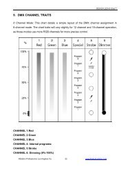
1. GREEN LAMP FUSE - This housing stores a 6 amp GMA protective<br />
fuse. The fuse is designed to protect the electronics in the event<br />
of severe power fluctuations. Always be sure to replace the fuse with<br />
an exact match as the one being replaced, unless otherwise told to do<br />
so by an authorized ©<strong>Elation</strong> service technician.<br />
2. RGB LED - When this LED is lit, the <strong>Stage</strong> <strong>Color</strong> is in RGB Mode.<br />
See Operatng Modes on page 11 for a description of this mode.<br />
3. C&B LED - When this LED is lit, the <strong>Stage</strong> <strong>Color</strong> is in C&B Mode.<br />
See Operatng Modes on page 11 for a description of this mode.<br />
4. COLOR LED - When this LED is lit, the <strong>Stage</strong> <strong>Color</strong> is in <strong>Color</strong><br />
Mode. See Operatng Modes on page 11 for a description of this<br />
mode<br />
5. DIGITAL DISPLAY - This 4-digit LED display shows the menu and<br />
operating functions that you can choose from. It also shows the unit’s<br />
current DMX address.<br />
7<br />
©<strong>Elation</strong> <strong>Professional</strong>® - www.elationlighting.com - <strong>Stage</strong> <strong>Color</strong> Instruction <strong>Manual</strong> Page 7 ©<strong>Elation</strong> <strong>Professional</strong>® - www.elationlighting.com - <strong>Stage</strong> <strong>Color</strong> Instruction <strong>Manual</strong> Page 8
<strong>Stage</strong> <strong>Color</strong><br />
Controls and Functions<br />
6. DOWN BUTTON - This button is used to scroll backwards through<br />
certain menu operations, and adjust the unit’s DMX address.<br />
7. XLR DMX IN - This jack is used to receive an incoming DMX<br />
signal or Master/Slave signal.<br />
8. XLR DMX OUT - This jack is used to transmit the incoming DMX<br />
signal to another DMX fixture, or transmit a Master/Slave signal to the<br />
next <strong>Stage</strong> <strong>Color</strong> in the chain. For best results in DMX or Master/<br />
Slave mode terminate this jack if it is the last unit in the chain. See<br />
“Terminator” on page 7.<br />
9. MODE BUTTON - This button is used to change the current operating<br />
mode, or access the unit’s internal menu options.<br />
10. UP BUTTON - This button is used to scroll forward through the<br />
system menu, and adjust the DMX address.<br />
11. DMX SIGNAL LED - This LED will flash repeatedly when the unit<br />
is receiving a DMX signal.<br />
12. BLUE LAMP FUSE - This housing stores a 6 amp GMA protective<br />
fuse. The fuse is designed to protect the electronics in the event of<br />
severe power fluctuations. Always be sure to replace the fuse with an<br />
exact match as the one being replaced, unless otherwise told to do so<br />
by an authorized ©<strong>Elation</strong> service technician.<br />
13. RED LAMP FUSE - This housing stores a 6 amp GMA protective<br />
fuse. The fuse is designed to protect the electronics in the event of<br />
severe power fluctuations. Always be sure to replace the fuse with an<br />
exact match as the one being replaced, unless otherwise told to do so<br />
by an authorized ©<strong>Elation</strong> service technician.<br />
<strong>Stage</strong> <strong>Color</strong><br />
Operation<br />
Operating Modes;<br />
The <strong>Stage</strong> <strong>Color</strong> can operate in several different modes and different<br />
operating modes may combined to function together. This section will<br />
describe the different modes, their function, and how to properly setup<br />
a unit for each function.<br />
• Stand alone mode - The unit can manually be set to any color<br />
combination or can chase through the built-in programs.<br />
• Master mode - You can daisy chain up to 16 units together to get<br />
a synchronized light show chasing through several built in programs.<br />
• Slave mode - Any unit set to slave mode will recieve it’s operating<br />
instruction from a master unit and must be linked to a unit functioning<br />
as a master unit. The slave function will work in either stand-alone or<br />
DMX modes.<br />
• DMX control mode - This function will allow you to individually<br />
control each of the traits with a standard DMX-512 controller such as<br />
the LSC® Show Designer. <br />
• RGB Mode - This mode is accessed when the unit is used in DMX<br />
mode with a DMX controller. In this mode the unit will function as a<br />
three channel color mixing par can. Each channel will have full dimmer<br />
functionallity. The first DMX channel will control the blue output,<br />
the second channel will control the red output, and the third will control<br />
the green output.<br />
• <strong>Color</strong> & Bright Mode - This mode is accessed when the unit is<br />
used in DMX mode with a DMX controller. In this mode the fixture wil<br />
function as a two channel DMX unit. In this mode channel one will<br />
control the color mixing and channel two will control the overall intensity.<br />
• <strong>Color</strong> Mode - This mode is accessed when the unit is used in DMX<br />
mode with a DMX controller. When <strong>Color</strong> mode is actvated, the overall<br />
output will be controlled by a single DMX channel. Intensity will be<br />
determinded by a preset level.<br />
©<strong>Elation</strong> <strong>Professional</strong>® - www.elationlighting.com - <strong>Stage</strong> <strong>Color</strong> Instruction <strong>Manual</strong> Page 9<br />
©<strong>Elation</strong> <strong>Professional</strong>® - www.elationlighting.com - <strong>Stage</strong> <strong>Color</strong> Instruction <strong>Manual</strong> Page 10
<strong>Stage</strong> <strong>Color</strong><br />
Operation<br />
Universal DMX Control: This function will allow you to control<br />
each of the fixtures DMX traits with a standard DMX 512 controller<br />
such as the LSC® Show Designer or DMX Operator. Operating<br />
through a DMX controller allows the freedom to create unique programs<br />
tailored to one’s individual needs.<br />
1. The <strong>Stage</strong> <strong>Color</strong> uses three DMX channels in RGB Mode, two<br />
channels in C & B Mode and one channel in <strong>Color</strong> Mode. (See<br />
page 11 for the description of the different modes.)<br />
2. To control your fixture in DMX mode, follow the unit set-up procedures<br />
beginning on page 5 as well as the set-up specifications<br />
that are included with your DMX controller.<br />
3. Use a 3-pin XLR data cables to form a connection between the<br />
<strong>Stage</strong> <strong>Color</strong> and a DMX Controller. Once a proper DMX connection<br />
is made, DMX activity will be indicated by a flashing LED in<br />
the digital display.<br />
4. In DMX address mode, the Display screen shows “A” followed by<br />
three numbers. You can select desired DMX address within 1- 512<br />
using UP/DOWN buttons.<br />
5. Once the DMX address has been set, press the MODE button to<br />
scroll to your desired mode.<br />
Stand Alone: This unit comes with 9 built-in chase programs that<br />
can be accessed without the use of a DMX controller. You are able<br />
to control the lamp intensity, the chase speed, and the fade time, of<br />
the built-in chase programs. (Please refer to page 14 for the Menu<br />
Structure).<br />
1. To access the chase program menu, press the MODE, UP and<br />
DOWN buttons, simultaneously..<br />
2. The LED screen will read P:10, meaning program number 10.<br />
3. By pressing the MODE button you can switch between the<br />
Program menu, and intensity adjustment for channel 1.<br />
4. When the unit is in Program menu, press and hold the MODE<br />
button, and press the either the UP or DOWN button. Pressing the<br />
UP button will take you to the Chase Speed Adjustment (SP:01). In<br />
<strong>Stage</strong> <strong>Color</strong><br />
this menu you can press either the UP or DOWN buttons to adjust<br />
the speed rate (1-99) in which the program chases.<br />
When you press and hold the MODE button and press the DOWN<br />
button takes you to Fade Time Adjustment (F:000). In this menu<br />
you can press either the UP or DOWN buttons to adjust the Fade<br />
Time (0-100%) of the unit.<br />
5. When the unit is in Channel 1 (blue) Intensity Adjustment, press<br />
and hold the MODE button and press either the UP or DOWN<br />
button. Pressing the UP button will take you to Channel 2 (red)<br />
Intensity Adjustment, while pressing the DOWN button will take<br />
you to Channel 3 (green) Intensity Adjustment. All Intensity levels<br />
can be adjusted from 0 - 100%.<br />
6. Pressing and holding the MODE button, UP button, and DOWN<br />
buttons will return the unit to the DMX address setting.<br />
Master/Slave Mode: Master/Slave mode allows you to link up to<br />
16 units together and operate without a controller. In Master-Slave<br />
operation one unit will act as the controlling unit and the others will<br />
react to the controlling units programs. Any unit can act as a Master<br />
or as a Slave. Follow the directions in Stand Alone mode to make<br />
adjustments to your selected program.<br />
1. Choose a unit to function as the Master and make all program<br />
adjustments on that unit. (See Stand Alone mode)<br />
2. Then simply daisy chain the units together using standard XLR<br />
microphone cables. Remember the Male XLR connector is the<br />
input and the Female XLR connector is the output. For longer<br />
cable runs we suggest a terminator at the last fixture.<br />
3. The slaves must be in DMX mode (address mode) to follow the<br />
masters’ program. The DMX address of the slaves does not matter.<br />
4. The slaves will now follow the masters’ program.<br />
Operation<br />
©<strong>Elation</strong> <strong>Professional</strong>® - www.elationlighting.com - <strong>Stage</strong> <strong>Color</strong> Instruction <strong>Manual</strong> Page 11 ©<strong>Elation</strong> <strong>Professional</strong>® - www.elationlighting.com - <strong>Stage</strong> <strong>Color</strong> Instruction <strong>Manual</strong> Page 12
<strong>Stage</strong> <strong>Color</strong> Menu Structure <strong>Stage</strong> <strong>Color</strong> Photometric Data<br />
Press Up or Down button<br />
Press and hold down Mode button<br />
d:050<br />
power on<br />
Setup Menu<br />
Structure:<br />
Overall<br />
intensity<br />
adjustment<br />
Mode<br />
d:100<br />
Mode+Up+Down<br />
To access Program menu,<br />
Press the Mode, Up, and<br />
Down buttons, Simultaneoulsy.<br />
50% to full<br />
intensity<br />
(50-100%)<br />
Master Mode<br />
Slave Mode<br />
Mode<br />
Press Mode<br />
button<br />
Mode<br />
Press Mode<br />
button<br />
Auto Mode<br />
<strong>Manual</strong> Mode<br />
Mode+Up Or<br />
Mode+Down<br />
While holding down<br />
Mode, press Up or<br />
Down<br />
Mode+Up<br />
Or<br />
While holding down<br />
Mode, press Up or<br />
Down<br />
<strong>Color</strong> Mode<br />
<strong>Color</strong> &<br />
Bright Mode<br />
RGB Mode<br />
A:001<br />
Mode+Down<br />
DMX<br />
Address<br />
adjustment<br />
Press Up or<br />
Down button<br />
to select between<br />
001 and 512<br />
P:01 SP:01 F:000<br />
1:001 2:001 3:001<br />
A:512<br />
Fade<br />
Time<br />
adjustment<br />
Chase<br />
Speed<br />
adjustment<br />
Chase<br />
Programs<br />
select<br />
intensity<br />
adjustment<br />
of channel 3<br />
intensity<br />
adjustment<br />
of channel 2<br />
intensity<br />
adjustment<br />
of channel 1<br />
Linkup function<br />
Press Up or Down button to adjust relevant parameter<br />
Press Up or Down button to select between 0 and 100<br />
1:100 2:100 3:100<br />
When two or more units are linked, the first unit will<br />
be assigned as the Master, and the other unit's as<br />
slaves.<br />
Fade Time<br />
0-100%<br />
1-99 chasing<br />
rates<br />
1-10 programs<br />
& a sequence<br />
of 10 programs<br />
Medium Lens<br />
©<strong>Elation</strong> <strong>Professional</strong>® - www.elationlighting.com - <strong>Stage</strong> <strong>Color</strong> Instruction <strong>Manual</strong> Page 13 ©<strong>Elation</strong> <strong>Professional</strong>® - www.elationlighting.com - <strong>Stage</strong> <strong>Color</strong> Instruction <strong>Manual</strong> Page 14<br />
Red<br />
Green<br />
Blue<br />
RGB<br />
Distance (feet)<br />
Beam Diameter (feet)<br />
Red<br />
Green<br />
Blue<br />
RGB<br />
Distance (feet)<br />
Beam Diameter (feet)<br />
Red<br />
Green<br />
Blue<br />
RGB<br />
Distance (feet)<br />
Beam Diameter (feet)<br />
540/50<br />
960/89<br />
280/26<br />
1720/160<br />
5<br />
5<br />
1030/96<br />
2200/205<br />
460/47<br />
2300/214<br />
490/45<br />
940/87<br />
282/26<br />
1260/117<br />
5<br />
7<br />
5<br />
3.5<br />
178/17<br />
320/30<br />
86/8<br />
520/49<br />
10<br />
10<br />
230/22<br />
560/52<br />
109/11<br />
820/77<br />
127/11<br />
265/24<br />
80/7<br />
320/30<br />
10<br />
14<br />
10<br />
5<br />
75/7<br />
169/16<br />
39/4<br />
218/21<br />
15<br />
15<br />
125/12<br />
250/24<br />
52/5<br />
420/39<br />
58/5<br />
120/11<br />
30/3<br />
178/17<br />
15<br />
21<br />
12° x 19°<br />
Beam Angle<br />
15<br />
10<br />
16° x 30°<br />
Beam Angle<br />
42/4<br />
103/10<br />
23/2<br />
144/14<br />
20<br />
20<br />
10°<br />
Beam Angle<br />
32/3<br />
67/6<br />
18/2<br />
110/11<br />
20<br />
28<br />
20<br />
15<br />
34/3<br />
62/6<br />
15/1<br />
92/9<br />
25<br />
25<br />
23/2<br />
48/4<br />
12/1<br />
67/7<br />
25<br />
35<br />
LUX/Foot-candles<br />
LUX/Foot-candles<br />
LUX/Foot-candles<br />
LUX/Foot-candles<br />
Optional Narrow Lens<br />
61/6<br />
140/13<br />
30/3<br />
220/21<br />
49/5 LUX/Foot-candles<br />
90/9 LUX/Foot-candles<br />
20/2 LUX/Foot-candles<br />
137/13 LUX/Foot-candles<br />
25<br />
20<br />
Optional Wide Lens<br />
LUX/Foot-candles<br />
LUX/Foot-candles<br />
LUX/Foot-candles<br />
LUX/Foot-candles
<strong>Stage</strong> <strong>Color</strong><br />
Beam Path<br />
<strong>Stage</strong> <strong>Color</strong><br />
RGB <strong>Color</strong> and DMX Value<br />
These illustrations represent the approximate intensity associated<br />
with a specific distance and beam diameter.<br />
DISTANCE (M) 1m 2m 6m 10m 16m<br />
Intensity<br />
(lux)<br />
0 (m) 1.1m 2.2m 5.32m 10.64m 15.96m<br />
Red<br />
Blue<br />
Green<br />
White<br />
<strong>Stage</strong> <strong>Color</strong><br />
4633<br />
6050<br />
6833<br />
9220<br />
DMX PROTOCAL (STAGE COLOR)<br />
1456 276 71<br />
32<br />
1782<br />
1891<br />
2840<br />
390<br />
325<br />
94<br />
79<br />
40<br />
37<br />
529 121 57<br />
DMX Traits<br />
--------- R G B MODE ----------<br />
DMX DMX Function Type of Control<br />
Channel Value<br />
1 0-255 Blue (Dimmer Intensity) Proportional<br />
Blue (0-off, 255-full Blue)<br />
2 0-255 Red (Dimmer Intensity) Proportional<br />
Red (0-off, 255-full red)<br />
3 0-255 Green (Dimmer Intensity) Proportional<br />
Green (0-off, 255-full Green)<br />
------- C & B MODE ----------<br />
DMX DMX Function Type of Control<br />
Channel Value<br />
1 0-255 <strong>Color</strong> Scroll Proportional<br />
Array of <strong>Color</strong>s from 0-100%<br />
2 0-255 Dimmer Intesity Proportional<br />
Gradual adjustment of the dimmer intensity<br />
From 0 to 100%<br />
------- COLOR MODE ----------<br />
DMX DMX Function Type of Control<br />
Channel Value<br />
1 0-255 <strong>Color</strong> Scroll Proportional<br />
Array of <strong>Color</strong>s from 0-100%<br />
RGB color and DMX value<br />
DMX Value<br />
Blue<br />
(Decimal) (Intensity, 0-100%)<br />
0 0<br />
1-2 100<br />
3-23 100<br />
34 100<br />
35-65 100-(N-34)x3<br />
66-69 0<br />
70-100 0<br />
101 0<br />
102-132 0<br />
133-136 0<br />
137-167 (N-136)x3<br />
168 100<br />
169-199 100<br />
200-206 100<br />
207 100<br />
208-210 100-(N-207)x12<br />
211 50<br />
212-215 50-(N-211)x6<br />
216-218 25-(N-215)x6<br />
219-222 (N-217)x6<br />
223-225 38+(N-223)x6<br />
226-228 50+(N-225)x12<br />
229 100<br />
230-232 100<br />
233 100<br />
234-236 100-(N-233)x12<br />
237 50<br />
238-240 50-(N-237)x6<br />
241-244 25-(N-241)x6<br />
245-247 (N-243)x6<br />
248-251 25+(N-247)x6<br />
252-254 50+(N-251)x12<br />
255 100<br />
Red<br />
(Intensity, 0-100%)<br />
0<br />
0<br />
(N-2)x3<br />
100<br />
100<br />
100<br />
100<br />
100<br />
100-(N-101)x3<br />
0<br />
0<br />
0<br />
0<br />
(N-199)x6<br />
50<br />
50+(N-207)x12<br />
100<br />
100<br />
100<br />
100<br />
100<br />
100<br />
100<br />
100-(N-229)x12<br />
50<br />
50-(N-233)x6<br />
25<br />
25-(N-237)x6<br />
(N-239)x6<br />
(N-239)x6<br />
50+(N-247)x12<br />
100<br />
100<br />
Green<br />
(Intensity, 0-100%)<br />
0<br />
0<br />
0<br />
0<br />
0<br />
0<br />
(N-69)x3<br />
100<br />
100<br />
100<br />
100<br />
100<br />
100-(N-168)x3<br />
(N-199)x12<br />
100<br />
100<br />
100<br />
100-(N-211)x12<br />
50-(N-215)x6<br />
25-(N-219)x6<br />
(N-221)x6<br />
25+(N-225)x6<br />
50<br />
50+(N-229)x12<br />
100<br />
100<br />
100<br />
100<br />
100<br />
100<br />
100<br />
100<br />
100<br />
NOTE:<br />
1. " N " denotes DMX value(0-255).<br />
For example:<br />
If DMX value is 239, blue intensity will be 50-(239-237)x6=38%,<br />
red intensity will be 25-(239-237)x6=13%, green intensity be 100%.<br />
2. " * " denotes unnameable color.<br />
<strong>Color</strong><br />
Black<br />
Blue<br />
*<br />
Blue & Red<br />
*<br />
Red<br />
*<br />
Red & Green<br />
*<br />
Green<br />
*<br />
Blue & Green<br />
*<br />
*<br />
*<br />
*<br />
*<br />
*<br />
*<br />
*<br />
*<br />
*<br />
*<br />
*<br />
*<br />
*<br />
*<br />
*<br />
*<br />
*<br />
*<br />
*<br />
White<br />
©<strong>Elation</strong> <strong>Professional</strong>® - www.elationlighting.com - <strong>Stage</strong> <strong>Color</strong> Instruction <strong>Manual</strong> Page 15<br />
©<strong>Elation</strong> <strong>Professional</strong>® - www.elationlighting.com - <strong>Stage</strong> <strong>Color</strong> Instruction <strong>Manual</strong> Page 16
<strong>Stage</strong> <strong>Color</strong><br />
Fuse & Lamp Replacement<br />
Halogen Lamp Warning! This fixture is fitted with<br />
halogen lamps which are highly susceptible to damage<br />
if improperly handled. Never touch the lamps<br />
with your bare fingers as the oil from your hands will<br />
shorten lamp life. Also, never move the fixture until<br />
the lamps have had ample time to cool. Remember,<br />
lamps are not covered under warranty conditions.<br />
Caution: Always replace with the exact same type lamps and fuses,<br />
unless otherwise specified by an authorized <strong>Elation</strong>® technician.<br />
Replacing with anything other than the specified part can damage<br />
the unit and will void the manufactures warranty.<br />
Warning: If after replacing a lamp or fuse, either one continues to<br />
blow, STOP using the unit. Contact customer support for further<br />
instructions, you may have to return the unit for servicing. Continuing<br />
to use the unit may cause serious damage.<br />
External Fuse Replacement: Disconnect the unit’s main power<br />
supply. Use a flat head screw driver to turn the fuse holder counter-clockwise,<br />
unlocking the fuse holder. Remove the fuse holder to<br />
expose the fuse. Remove the old fuse and discard it. Replace the<br />
fuse with the same type. Insert the fuse holder back into it’s housing<br />
and turn it in a clockwise direction to lock the holder in place.<br />
Internal Fuse Replacement: Disconnect the unit’s main power<br />
supply. Using a phillips screwdriver, unscrew and remove the three<br />
screws from the back cover of the <strong>Stage</strong> <strong>Color</strong>. Gently, pull the rear<br />
panel cover up. Be aware of the wires that are connected to the rear<br />
panel cover and unit. Let the cover rest to the side of the unit. Inside<br />
the unit located near the AC cord connection, is the internal fuse.<br />
Remove the old fuse and discard it. Replace the fuse with the same<br />
type, and reassemble in reverse order.<br />
Lamp Replacement: Caution! Never attempt to change the lamp<br />
while the fixture is plugged in. Always disconnect the main power and<br />
allow the unit ample time to cool before attempting to replace the lamp.<br />
1. Be sure to follow the proper handling procedures that deal with<br />
halogen lamps.<br />
2. Remove the three thumb screws located near the the front of the<br />
unit.<br />
3. Gently pull the lens assembly out of the unit by using the provid-<br />
©<strong>Elation</strong> <strong>Professional</strong>® - www.elationlighting.com - <strong>Stage</strong> <strong>Color</strong> Instruction <strong>Manual</strong> Page 17<br />
<strong>Stage</strong> <strong>Color</strong><br />
<strong>Stage</strong> <strong>Color</strong><br />
Fuse & Lamp Replacement<br />
ed handles. Be sure to be careful when removing the lens assembly.<br />
4. Carefully remove the old lamp(s) and discard it in the trash.<br />
Replace the lamp with an exact match.<br />
5. When reassembling pay attention, the lens assembly will only<br />
slide back in one way. Pay attention to the slots on the inside of<br />
the unit, one slot is fat and two slots are thin.<br />
Trouble Shooting<br />
Trouble Shooting: Listed below are a few common problems that<br />
you may encounter, with solutions.<br />
No light output from the unit;<br />
1. Be sure you have connected your unit into a standard 120V (or<br />
220v depending on the models voltage requirements) wall outlet.<br />
2. Be sure the external and internal fuse have not blown. The external<br />
fuse is located on the rear panel of the unit. Be sure the fuse<br />
holders are completely and properly seated.<br />
3. Remove the lamp cover and be sure the lamps are seated in their<br />
socket properly. Occasionally lamps become loose during shipping<br />
be sure the lamp is push in to its socket all the way.<br />
Remember: Do not touch the lamp with your bare fingers.<br />
<strong>Stage</strong> <strong>Color</strong><br />
Cleaning<br />
Fixture Cleaning: Due to fog residue, smoke, and dust cleaning<br />
the internal and external optical lenses should be carried out periodically<br />
to optimize light output. Cleaning frequency depends on the<br />
environment in which the fixture operates (I.e. smoke, fog residue,<br />
dust, dew). In heavy club use we recommend cleaning on a monthly<br />
basis. Periodic cleaning will ensure longevity, and crisp output.<br />
1. Use normal glass cleaner and a soft cloth to wipe down the outside<br />
casing.<br />
2. Use a brush to wipe down the cooling vents and fan grill.<br />
3. Clean the external lens with glass cleaner and a soft cloth every<br />
20 days.<br />
4. Clean the internal optics with glass cleaner and a soft cloth every<br />
30-60 days.<br />
5. Always be sure to dry all parts completely before plugging the unit<br />
back in.<br />
©<strong>Elation</strong> <strong>Professional</strong>® - www.elationlighting.com - <strong>Stage</strong> <strong>Color</strong> Instruction <strong>Manual</strong> Page 18
<strong>Stage</strong> <strong>Color</strong><br />
2-YEAR LIMITED WARRANTY<br />
Warranty<br />
A. <strong>Elation</strong> <strong>Professional</strong>® hereby warrants, to the original purchaser, <strong>Elation</strong> <strong>Professional</strong>®<br />
products to be free of manufacturing defects in material and workmanship for a period of 2<br />
Years (730 days) from the date of purchase. This warranty shall be valid only if the product<br />
is purchased within the United States of America, including possessions and territories.<br />
It is the owner’s responsibility to establish the date and place of purchase by acceptable<br />
evidence, at the time service is sought.<br />
B. For warranty service, send the product only to the <strong>Elation</strong> <strong>Professional</strong>® factory. All<br />
shipping charges must be pre-paid. If the requested repairs or service (including parts<br />
replacement) are within the terms of this warranty, <strong>Elation</strong> <strong>Professional</strong>® will pay return shipping<br />
charges only to a designated point within the United States. If the entire instrument<br />
is sent, it must be shipped in its original package. No accessories should be shipped with<br />
the product. If any accessories are shipped with the product, <strong>Elation</strong> <strong>Professional</strong>® shall<br />
have no liability whatsoever for loss of or damage to any such accessories, nor for the safe<br />
return thereof.<br />
C. This warranty is void if the serial number has been altered or removed; if the product is<br />
modified in any manner which <strong>Elation</strong> <strong>Professional</strong>® concludes, after inspection, affects the<br />
reliability of the product; if the product has been repaired or serviced by anyone other than<br />
the <strong>Elation</strong> <strong>Professional</strong>® factory unless prior written authorization was issued to purchaser<br />
by <strong>Elation</strong> <strong>Professional</strong>®; if the product is damaged because not properly maintained as set<br />
forth in the instruction manual.<br />
D. This is not a service contract, and this warranty does not include maintenance, cleaning<br />
or periodic check-up. During the period specified above, <strong>Elation</strong> <strong>Professional</strong>® will replace<br />
defective parts at its expense, and will absorb all expenses for warranty service and repair<br />
labor by reason of defects in material or workmanship. The sole responsibility of <strong>Elation</strong><br />
<strong>Professional</strong>® under this warranty shall be limited to the repair of the product, or replacement<br />
thereof, including parts, at the sole discretion of <strong>Elation</strong> <strong>Professional</strong>®. All products<br />
covered by this warranty were manufactured after January 1, 1990, and bear identifying<br />
marks to that effect.<br />
E. <strong>Elation</strong> <strong>Professional</strong>® reserves the right to make changes in design and/or improvements<br />
upon its products without any obligation to include these changes in any products<br />
theretofore manufactured.<br />
F. No warranty, whether expressed or implied, is given or made with respect to any accessory<br />
supplied with products described above. Except to the extent prohibited by applicable<br />
law, all implied warranties made by <strong>Elation</strong> <strong>Professional</strong>® in connection with this product,<br />
including warranties of merchantability or fitness, are limited in duration to the warranty<br />
period set forth above. And no warranties, whether expressed or implied, including warranties<br />
of merchantability or fitness, shall apply to this product after said period has expired.<br />
The consumer’s and or Dealer’s sole remedy shall be such repair or replacement as is<br />
expressly provided above; and under no circumstances shall <strong>Elation</strong> <strong>Professional</strong>® be liable<br />
for any loss or damage, direct or consequential, arising out of the use of, or inability to use,<br />
this product.<br />
G. This warranty is the only written warranty applicable to <strong>Elation</strong> <strong>Professional</strong>® Products<br />
and supersedes all prior warranties and written descriptions of warranty terms and conditions<br />
heretofore published.<br />
H. Lamps are not covered under this or any other warranty, either written or implied.<br />
©<strong>Elation</strong> <strong>Professional</strong>® - www.elationlighting.com - <strong>Stage</strong> <strong>Color</strong> Instruction <strong>Manual</strong> Page 19<br />
Model: <strong>Stage</strong> <strong>Color</strong><br />
Specifiations:<br />
Power Input:<br />
AC 120V~ 50-60Hz<br />
Lamps<br />
3 x ZB-HX600 120v-575w-3200k-300hrs<br />
Optional Lamps ZB-HX601, 120v-575w-3050k-1500hrs<br />
ZB-HX400, 120v-400w-3200k-300hrs<br />
ZB-HX401, 120v-400w-3040k-1500hrs<br />
External Fuse<br />
3 x 6A GMXA, 250V<br />
5x20mm<br />
Internal Fuse<br />
7A GMA, 250V 5x20mm<br />
DMX Channels<br />
3 Channels<br />
DMX Input/Output<br />
3-Pin<br />
Dimensions 10” x 8.5” x 18”<br />
258x220x458mm<br />
Weight<br />
10lbs / 4.65 Kg<br />
Warranty<br />
2 Years (720 Days)<br />
Please Note: Specifications and improvements in the design of<br />
this unit and this manual are subject to change without any prior<br />
written notice.<br />
<strong>Elation</strong> <strong>Professional</strong>®<br />
Part of the American DJ® Group of Companies<br />
©<strong>Elation</strong> <strong>Professional</strong>® World Headquarters:<br />
4295 Charter Street Los Angeles, CA 90058 USA<br />
Tel: 323-582-3322 Fax: 323-582-3311<br />
Web: www.elationlighting.com E-mail: info@elationlighting.com