Rolling Element Bearing Acceptance and Life Testing (BAT)
Rolling Element Bearing Acceptance and Life Testing (BAT)
Rolling Element Bearing Acceptance and Life Testing (BAT)

Create successful ePaper yourself
Turn your PDF publications into a flip-book with our unique Google optimized e-Paper software.
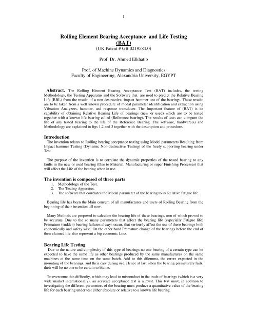
<strong>Rolling</strong> <strong>Element</strong> <strong>Bearing</strong> <strong>Acceptance</strong> <strong>and</strong> <strong>Life</strong> <strong>Testing</strong><br />
(<strong>BAT</strong>)<br />
(UK Patent # GB 0219584.0)<br />
Prof. Dr. Ahmed Elkhatib<br />
Prof. of Machine Dynamics <strong>and</strong> Diagnostics<br />
Faculty of Engineering, Alex<strong>and</strong>ria University, EGYPT<br />
Abstract. The <strong>Rolling</strong> <strong>Element</strong> <strong>Bearing</strong> <strong>Acceptance</strong> Test (<strong>BAT</strong>) includes, the testing<br />
Methodology, the <strong>Testing</strong> Apparatus <strong>and</strong> the Software that are used to predict the Relative <strong>Bearing</strong><br />
<strong>Life</strong> (RBL) from the results of a non-destructive, impact hammer test of the bearings. These results<br />
are to be taken from a well known procedure of modal parameter identification <strong>and</strong> extraction using<br />
Vibration Analyzers, hammer, <strong>and</strong> response transducer. The Important feature of (<strong>BAT</strong>) is its<br />
capability of obtaining Relative <strong>Bearing</strong> <strong>Life</strong> of bearings (new or used) which are to be tested<br />
together with a known life bearing called (Reference bearing). The results of tests can compare the<br />
life of any tested bearing to the life of the Reference <strong>Bearing</strong>. The software, hardware(s) <strong>and</strong><br />
Methodology are explained in figs 1,2 <strong>and</strong> 3 together with the description <strong>and</strong> procedure.<br />
Introduction<br />
The invention relates to <strong>Rolling</strong> bearing acceptance testing using Model parameters Resulting from<br />
Impact hammer <strong>Testing</strong> (Dynamic Non-destructive <strong>Testing</strong>) of the freely supporting bearing under<br />
Test.<br />
The purpose of the invention is to correlate the dynamic properties of the tested bearing to any<br />
faults in the new or used bearing (Due to Material, Manufacturing or super Finishing Processes) that<br />
will affect the <strong>Life</strong> of the bearing when in use.<br />
The invention is composed of three parts<br />
1. Methodology of the Test.<br />
2. The <strong>Testing</strong> Apparatus.<br />
3. The software that correlates the Modal parameter of the bearing to its Relative fatigue life.<br />
<strong>Bearing</strong> life has been the Main concern of all manufactures <strong>and</strong> users of <strong>Rolling</strong> <strong>Bearing</strong> from the<br />
beginning of their invention till now.<br />
Many Methods are proposed to calculate the bearing life of these bearings, non of which proved to<br />
be accurate. Due to the so many parameters that affect the bearing life (especially Fatigue life)<br />
Premature (sudden) bearing failures always occur, that seriously affect the use of these bearings both<br />
economically <strong>and</strong> safety wise. On the other h<strong>and</strong> Premature change of the bearings before the end of<br />
their claimed life also represent a big economic Loss.<br />
<strong>Bearing</strong> <strong>Life</strong> <strong>Testing</strong><br />
Due to the nature <strong>and</strong> complexity of this type of bearings no one bearing of a certain type can be<br />
expected to have the same life as other bearings produced by the same manufactures on the same<br />
machines at the same time on the same batch. Add to this dilemma, the errors expected in the<br />
mounting of the bearings, <strong>and</strong> their care during use. Hence at last when the bearing prematurely fails,<br />
their will be no one to be certain to blame.<br />
To overcome this difficulty, which may lead to misconduct in the trade of bearings (which is a very<br />
wide market internationally), an accurate acceptance test is a must. This test must, in addition to<br />
investigating the different parameters of the bearing must produce a quantitative value of the bearing<br />
life for each bearing under test either absolute or relative to a known life bearing.
A test of this kind must be simple, accurate <strong>and</strong> cheap. This invention introduces a br<strong>and</strong> new<br />
acceptance testing Methodology based on the bearing fatigue life <strong>and</strong> presents two types of apparatus<br />
for testing <strong>and</strong> at last a software for transforming the results of the dynamic tests into bearing life<br />
indices.<br />
The basics of the invention are depending on Modal testing that will need the presence of vibration<br />
analyzer (2-channels FFT at least), any analyzer in the market can fulfill this requirement.<br />
The bearing under test is to be freely supported either using Method (A) represented in fig. A or<br />
Method (B) represented in fig.(B) <strong>and</strong> in either support the bearing will receive several blows (at least<br />
4 blows) from an instrumented impact hammer (used in conjunction with vibration analyzer) <strong>and</strong> the<br />
results of the bearing response to these blows are taken via a vibration sensor (Accelerometer)<br />
attached (by wax) to the outer ring of the bearing. Each of the value of the strength of the hammer<br />
blows <strong>and</strong> the responses are fed to a separate channel of the vibration analyzer. The vibration<br />
analyzer (equipped with analysis software) will produce the Transfer Function of the bearing under<br />
test this transfer function represents the DNA of each bearing. To get accurate results the transfer<br />
function is monitored by a corresponding value called the coherence function (both functions are<br />
produced by the vibration analyzer). Values of transfer function at Resonance that corresponds to a<br />
coherence value of about (0.990) or more up to (1.000) is considered accurate. Values at coherence<br />
less than (0.99) should be discarded <strong>and</strong> the test repeated. This is taken care off in our invented<br />
software (<strong>BAT</strong>). This software taken automatically, the values of the modal parameters for accurate<br />
tests (Modal frequency) modal transfer function at resonance, <strong>and</strong> Modal damping) <strong>and</strong> correlates<br />
then to a value of bearing life that can be compared to the corresponding value for a given reference<br />
bearing (known to be of accepted life). The software (<strong>BAT</strong>) will produce a report for the modal<br />
parameters of all tested bearings (of same type) together with the reference bearing <strong>and</strong> will also<br />
produce the Relative <strong>Bearing</strong> life index, considering the bearing life of the reference bearing as unity<br />
<strong>and</strong> compares the values calculated for the bearing life of each tested bearing with that of the<br />
reference bearing to categorize each bearing according to the ratio of its bearing life value to the<br />
reference bearing.<br />
If this technique is used as a quality control test at the end of batch production line of bearing of a<br />
certain type <strong>and</strong> dimension at a bearing manufacture facility, absolute bearing life values can be<br />
obtained by applying the test for each produced bearing at the end of the bearing assembly line <strong>and</strong><br />
obtaining the bearing fatigue life value using (<strong>BAT</strong>) then one bearing of the batch is taken for an<br />
actual running test (under given conditions) until it fails.<br />
The actual life of this bearing is thus correctly known. This bearing can be considered as the<br />
reference bearing <strong>and</strong> absolute lives of All other bearings in the batch can thus be easily determined.<br />
Hence each bearing can be marked with its actual absolute life under the tested conditions.<br />
The bearing consumer can thus have an awareness technique that given then accurate values of<br />
bearing life for each bearing they are going to purchase.<br />
Thus this invention can be used either as an acceptance test or a quality control test.<br />
Procedure of Work<br />
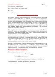
A. Manual <strong>Testing</strong> (Fig1):<br />
1. The Reference <strong>Bearing</strong> (<strong>Bearing</strong> recommended to be acceptable or of known life value) is to<br />
be hanged vertically, using an elastic rubber b<strong>and</strong>, to the rigid support.<br />
2. An Instrumented impact hammer (fitted with line drive amplifier <strong>and</strong> a force transducer) is<br />
to be used to strike the outer race of the bearing with four (4) repeated light impacts in a any<br />
chosen direction at any chosen point. The value of the impact signal is to be taken from the<br />
hammer to channel (1) of (at least) Two channel Vibration Analyzer.<br />
3. The response signal of the bearing to each hammer blow is taken through the accelerometer<br />
attached (by bees wax) to a point on the bearing at opposite side of the outer race (opposite<br />
to striking point). This accelerometer is connected to channel (2) of the Vibration Analyzer.
4. After averaging of the results of the 4 strikes, the analyzer will show the Transfer Function<br />
of the bearing represented as represented in a fig.4.This Transfer Function will contain the<br />
modal parameters (Modal frequency, Modal mobility, <strong>and</strong> Modal damping) for the first<br />
mode of vibration that will be extracted by (<strong>BAT</strong>) software.<br />
5. Steps 1-4 above are to be repeated for All bearings to be tested.<br />
6. <strong>BAT</strong> software will make the necessary calculations <strong>and</strong> will produce a report containing the<br />
modal parameters of all tested bearings together with their expected lives relative to the<br />
Reference <strong>Bearing</strong>.<br />
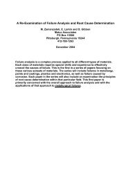
B. Automatic <strong>Testing</strong> (Fig2):<br />
1. Each bearing is to be clamped on the PVC collect rested on the bearing carriage which is<br />
moving (without friction) on the air pad.<br />
2. The motor is to be switch on, this will cause the bearing carriage to move a way from the<br />
hammer carriage.<br />
3. In its way, the bearing carriage will press the limit switch 1 which will release the motor<br />
power <strong>and</strong> will send the bearing carriage for- word to impact with the hammer tip situated<br />
on the other end of the air pad<br />
4. While the bearing is striking the hammer, the bearing carriage will press limit switch 2<br />
which will energize the motor again to pull the bearing carriage away from the striking<br />
position.<br />
5. Steps 3,4 are repeated many times (4 or more) governed by the counter circuitry given in<br />
fig.3 to average the results.<br />
6. The switches <strong>and</strong> the motor drive circuitry are given also in fig.3.<br />
7. Same procedure of signal detection, acquisition, Modal Parameter calculation <strong>and</strong> relative<br />
bearing life calculation as in (A) above, is used (step 4 to step 6).<br />
Rubber B<strong>and</strong><br />
Impact Hammer<br />
Rigid<br />
Support<br />
<strong>Bearing</strong><br />
Under Test<br />
Accelerometer<br />
Excitation signal<br />
(Channel 1)<br />
Figure (1)<br />
Response signal<br />
(Channel 2)
To Channel 1 To Channel 2<br />
Air jets<br />
Accelerometer<br />
Hammer Tip<br />
Force<br />
<strong>Bearing</strong> Under Test<br />
Transducer<br />
Air inlet<br />
S.V<br />
Air pad<br />
Limit switch 2<br />
Elevation<br />
Limit switch 1<br />
Linear Air-<strong>Bearing</strong><br />
Spring<br />
PVC Collet<br />
Motor<br />
Air Supply<br />
Hammer Carriage<br />
Spring<br />
<strong>Bearing</strong> Carriage<br />
Figure 2<br />
Plan<br />
Control of <strong>Bearing</strong> Carriage Motion<br />
1. Devices used for motion control<br />
a. DC Motor<br />
The DC Motor is connected to the bearing carriage mechanically by a string <strong>and</strong> pulley<br />
system at the end of the air pad<br />
b. Limit switches<br />
Limit switches are used to determine the bearing carriage position. The first limit<br />
switch (1) is positioned at the beginning of the carriage stroke. When the carriage is<br />
released the switch will generate a stop signal to stop the motor. The second limit<br />
switch (2) is positioned at the end of the bearing carriage stroke .At this point the<br />
bearing will strike the hammer <strong>and</strong> the switch will generate a start signal to start the<br />
motor <strong>and</strong> pull the bearing carriage back to the initial position.<br />
c. R-S Latches<br />
R-S Latches are used to reshape the pulse <strong>and</strong> eliminate any disturbing noise that may<br />
affect the control pulse.<br />
d. Toggle J-K flip-flop<br />
Toggle J-K flip-flop used to toggle the pulse that controls the operation of the motor<br />
(ON-OFF).<br />
e. Transistor:<br />
Transistor is used to amplify the J-K flip-flop output current.<br />
f. Normally Open Relay<br />
Normally open relay is used to operate the motor.<br />
2. Devices used for repeating the motion<br />
a. Divided /5 counter<br />
b. Seven segments display<br />
c. Reset circuit
Figure (3)
[N]<br />
400<br />
Time(Excitation) - Current<br />
Working : Input : Input : FFT Analyzer<br />
200<br />
0<br />
-200<br />
-400<br />
0 4m 8m 12m 16m 20m 24m 28m 32m 36m 40m 44m 48m 52m 56m 60m<br />
[s]<br />
[N²/Hz s]<br />
1.2m<br />
Autospectrum(Excitation) - Current<br />
Working : Input : Input : FFT Analyzer<br />
800u<br />
400u<br />
0<br />
0 400 800 1.2k 1.6k 2k 2.4k 2.8k 3.2k 3.6k 4k 4.4k 4.8k 5.2k 5.6k 6k 6.4k<br />
[Hz]<br />
Figure (4) time wave form <strong>and</strong> frequency spectrum for the applied<br />
impulse.<br />
[V]<br />
Time(Response) - Current<br />
Working : Input : Input : FFT Analyzer<br />
4<br />
0<br />
-4<br />
[V]<br />
20m<br />
16m<br />
12m<br />
8m<br />
4m<br />
0<br />
0 2m 4m 6m 8m 10m 12m 14m 16m 18m 20m 22m 24m<br />
[s]<br />
Autospectrum(Response) - Current<br />
Working : Input : Input : FFT Analyzer<br />
0 400 800 1.2k 1.6k 2k 2.4k 2.8k 3.2k 3.6k 4k 4.4k 4.8k 5.2k 5.6k 6k 6.4k<br />
[Hz]<br />
Figure (5) time wave form <strong>and</strong> frequency spectrum for the bearing<br />
response.
[V/N]<br />
200m<br />
160m<br />
Frequency Response H1(Response,Excitation) - Current (Magnitude)<br />
Working : Input : Input : FFT Analyzer<br />
Status<br />
5/7/02 14:18:07.759<br />
Averages: 4<br />
Overload: 0.00 %<br />
120m<br />
80m<br />
40m<br />
0<br />
0 400 800 1.2k 1.6k 2k 2.4k 2.8k 3.2k 3.6k 4k 4.4k 4.8k 5.2k 5.6k 6k 6.4k<br />
[Hz]<br />
Resonance<br />
Frequency = 3.1760k Hz<br />
Delta f 3dB = 986.54 Hz<br />
Damping Ratio = 15.5 %<br />
Residue = 318 V/N Hz<br />
Cursor Values<br />
Y = 102m V/N<br />
X = 3.1760k Hz<br />
[]<br />
Coherence(Response,Excitation) - Current<br />
Working : Input : Input : FFT Analyzer<br />
1<br />
800m<br />
Cursor Values<br />
Y = 997m<br />
X = 3.1760k Hz<br />
600m<br />
400m<br />
200m<br />
0<br />
0 400 800 1.2k 1.6k 2k 2.4k 2.8k 3.2k 3.6k 4k 4.4k 4.8k 5.2k 5.6k 6k 6.4k<br />
[Hz]<br />
Status<br />
5/7/02 14:18:07.759<br />
Averages: 4<br />
Overload: 0.00 %<br />
Fig(6) frequency response function <strong>and</strong> coherence function.