AUTOMATED BEARING WEAR DETECTION Alan Friedman DLI ...
AUTOMATED BEARING WEAR DETECTION Alan Friedman DLI ...
AUTOMATED BEARING WEAR DETECTION Alan Friedman DLI ...

Create successful ePaper yourself
Turn your PDF publications into a flip-book with our unique Google optimized e-Paper software.
<strong>AUTOMATED</strong> <strong>BEARING</strong> <strong>WEAR</strong> <strong>DETECTION</strong><br />
<strong>Alan</strong> <strong>Friedman</strong><br />
<strong>DLI</strong> Engineering<br />
253 Winslow Way W<br />
Bainbridge Island, WA 98110<br />
PH (206)-842-7656 - FAX (206)-842-7667<br />
info@dliengineering.com<br />
Published in Vibration Institute Proceedings 2004<br />
Abstract: The following paper will describe a methodology for automatically detecting and diagnosing<br />
rolling element bearing wear. The techniques involved have been proven in over 15 years of use in a huge<br />
variety of environments, machine types and applications. The techniques involved in diagnosing bearing<br />
wear will be described in detail and supported by a set of example graphs and an annotated diagnostic<br />
report.<br />
Key Words: Bearing wear; expert system; ball bearing fault detection; inner race fault; outer race fault;<br />
demodulation; cepstrum analysis; vibration analysis.<br />
Introduction: Rolling element bearing wear will create a variety of different patterns in spectral data<br />
depending on the geometry of the bearing, the type and degree of wear, and the operating condition of the<br />
machine. Therefore, an automated diagnostic system approach to bearing wear detection must be capable of<br />
interpreting a huge array of spectral patterns and differentiating bearing wear from other machine faults or<br />
external causes. Although knowledge of the bearing geometry may be useful in calculating expected fault<br />
frequencies, a versatile diagnostic system should be able to detect bearing wear without requiring this<br />
information. Both of these requirements have been met in this system.<br />
Summary of Techniques: The automated bearing wear detection algorithms combine a number of well<br />
proven techniques to detect and confirm the presence of bearing defects. These include:<br />
• Data normalization<br />
• Automated spectral peak extraction<br />
• Cepstrum analysis<br />
• Noise floor calculation<br />
• Bearing wear logical rules<br />
• Demodulation.<br />
Each of these concepts will be reviewed and explained in the following document with respect to its<br />
contribution to automating the detection of rolling element bearing wear.<br />
Data Normalization: Because bearing tones in a vibration spectrum are non-synchronous, in other words,<br />
they are not integer multiples of shaft speed, the first order of business is to determine shaft speed and<br />
exclude peaks that are synchronous. This is accomplished by an automated data normalization routine. If<br />
actual shaft speed is known via a tachometer, manual input or other mechanism, the algorithm will simply<br />
use this value. If the shaft speed is not known, which is typical in variable frequency drives, the algorithm<br />
will search for a peak at the nominal machine speed plus or minus a percentage window set by the user. Up<br />
to ten user-defined forcing frequencies are also used by the normalization routine. The forcing frequencies<br />
help determine the pattern of the expected spectrum and the algorithm can successfully match the pattern<br />
even if some peaks are missing, including a strong shaft rate peak.
Automated Spectral Peak Extraction: Once the data have been normalized, 10 user defined forcing<br />
frequencies are extracted from each of the spectra*. Next, the two highest undefined peaks are extracted<br />
from each spectrum. These are likely candidates for bearing tones. Data may be collected in all three axes<br />
and two frequency ranges for each test location, bringing the total number of potential bearing tone<br />
candidates to up to 12 per test location. When the human analyst attempts to find bearing tones, the same<br />
process is used. Known peaks are defined and excluded then un-defined, non synchronous peaks are<br />
considered as bearing tone candidates.<br />
Beyond the 10 user defined forcing frequencies, an array of related peaks will also be extracted and<br />
disregarded as possible bearing tones as described below. This is to say that there is a logical order of<br />
determining the likely source of a peak and the conclusion that it is a bearing tone only comes after all<br />
other logical explanations have been discredited. As an example of this, if the user defines the motor bar<br />
pass frequency, the system will automatically extract 2x line frequency sidebands around this peak and will<br />
disqualify them as bearing tones. (Even though they will be non synchronous and may not have been<br />
specifically defined by the user). These criteria would apply to a 2x line frequency peak in an AC motor as<br />
well, even if it was not defined. If the machine was defined as a diesel engine however, a peak at 120 Hz<br />
might be considered a bearing tone as 2x line frequency should not appear in this type of machine.<br />
*peak extraction footnotes: If bearing tones have been manually identified by the user, these may be<br />
included in the user defined forcing frequencies. Known external vibration or other spectral peaks that may<br />
be confused with bearing tones may also be defined and excluded from the bearing analysis, including<br />
whole harmonic families. Consistent external vibration may also be included in the baseline spectra and<br />
ignored in this fashion. An example of this might be the constant presence of diesel engine vibration in<br />
shipboard machinery.<br />
Cepstrum Analysis: Once a bearing tone candidate peak has been defined, it is important to determine if<br />
the peak is part of a family of peaks or not. Bearing tones, especially in later stages of wear, will have<br />
harmonics and may have sidebands; both of these are considered part of the same family of peaks in that<br />
they are related to the fundamental bearing tone. One may also say in a general sense that the more<br />
harmonics and sidebands present, the worse the condition of the bearing. Thus, not only does one wish to<br />
know if this peak is part of a larger family of peaks, one also wants to get an idea of how much energy is<br />
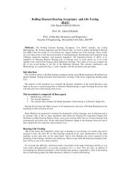
contained in the series. Cepstrum analysis is used for automating this task. The Cepstrum is a power<br />
spectrum of a power spectrum of a waveform; therefore, any periodicities in the spectrum (such as<br />
harmonic series or sideband families) will clearly appear as a peak in the Cepstrum.<br />
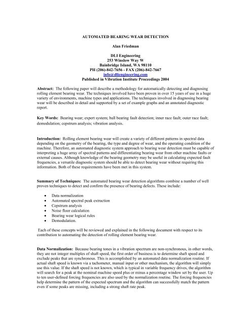
To better explain Cepstrum, let’s say we have a motor driving a fan via a belt. The motor runs at 1800 RM<br />
and will create a peak at 1800 RPM in the spectra along with harmonics (multiples) of this peak at 3600,<br />
5400, 7200 RPM etc. The fan is running at 1000 RPM and the belt at 90 RPM. Both of these components<br />
will create peaks at their frequencies plus harmonics. Thus, we now have 3 families of peaks in our<br />
spectrum, one related to the motor, one to the fan and one to the belt. If we do a Cepstrum of this plot, we<br />
will have only 3 peaks at 1800, 1000 and 90 RPM. Thus the Cepstrum reduces the complex spectra to its<br />
fundamental families. If there was a bearing tone in this spectrum at 9100 CPM with harmonics, an<br />
additional peak at 9100 will appear in the Cepstrum. A sample Cepstrum plot can be found in figure 1<br />
below.<br />
Additionally, if we had the following series of peaks in our spectrum: 6.2x, 9.3x, 12.4x, 15.5x, 21.7x, we<br />
could say that this is a series of harmonics of 3.1x, even though 3.1x is not present in the list, and neither is<br />
18.6x. Cepstrum would also announce that the fundamental frequency in this series is 3.1x because this is<br />
the spacing between each of these peaks. Thus, we can find bearing related peaks even if the fundamental<br />
bearing tone (3.1x in this case) is not present.<br />
Although fundamental bearing tones may be calculated if one knows the bearing geometry, in reality these<br />
fundamental tones may not be prominent in the spectral data even when a fault is present. In fact, bearing
wear can create all sorts of patterns in the spectral data that are not related to calculated frequencies. At the<br />
same time, there is a commonality to all bearing wear, and this is the presence of a series of nonsynchronous<br />
peaks and sideband families. Cepstrum analysis is used to extract periodicities from the<br />
spectrum and will therefore find bearing tones even when the fundamental bearing tone frequency is not<br />
present. In this sense, Cepstrum not only makes it unnecessary to know the bearing geometry, it also makes<br />
it more likely a bearing fault will be correctly diagnosed when the pattern produced is not a text book<br />
example of the fault.<br />
140<br />
CdB<br />
130<br />
120<br />
110<br />
100<br />
Bearing Tones<br />
1X Harmonics<br />
90<br />
80<br />
70<br />
60<br />
.006 .003 .002 .0015<br />
Time, Seconds<br />
(Figure 1: Cepstrum of a Single Shaft Machine with Bearing Wear)<br />
Noise Floor Calculation: Both impacts and random noise in a time waveform cause the spectrum to<br />
become elevated (as in Figure 3, below the largest peak). As bearings wear, they typically produce larger<br />
quantities of non-periodic vibration and impacts. This raises the noise floor of the spectrum. The automated<br />
diagnostic system uses an algorithm to calculate the level of the noise floor. This value is then compared to<br />
a baseline value if one is available. Increases in noise floor level add to the severity of the bearing wear<br />
diagnosis and may even trigger a diagnosis in certain cases when bearing tones are not evident.<br />
Other factors that may contribute to an increased severity are shaft rate harmonics and sub-harmonics. Both<br />
of these patterns are related to mechanical looseness, however, one can say that as bearings wear, the shaft<br />
may loosen up and therefore as the wear progresses, one may also witness more and more signs of<br />
mechanical looseness in the spectral data.<br />
Shaft rate harmonics and sub harmonics may be automatically extracted from the spectral data and used in<br />
this fashion. Calculations may also be performed on these groups of peaks and used in the rule base. For<br />
example, the sum of the exceedances of the first 10 harmonics of shaft rate will be used in some rules<br />
instead of the individual amplitudes of each harmonic.<br />
Bearing Wear Logical Rules: There are hundreds of individual rules for bearing wear in the bearing wear<br />
diagnostic system. These rules are activated by machinery component type as defined by the user. For<br />
example, a rule for bearing wear in a compressor will look slightly different from the rule for bearing wear<br />
in an AC motor. Each individual machine component type may have numerous rules for bearing wear that<br />
will be applied. If the requirements for a rule are satisfied, it means the condition exists.<br />
After information has been extracted from the spectra as described above, it is passed through all of the<br />
rules that apply to the general machine type to see if any faults exist. The rules are empirically based on<br />
thousands of machine tests collected over more than 20 years and are constantly refined as new information
ecomes available. If a rule is edited for any reason, the change is run through all of our historical data to<br />
ensure that it does not change any previously correct results. This is how the system “learns” and this is one<br />
reason why it is so accurate today.<br />
A typical rule looks something like this in terms of its logic:<br />
1. If the sum of the exceedance over baseline of all perceived bearing tones in all three axes and all<br />
test points (Cepstrum confirmed) is higher than a threshold, or the sum of the noise floor readings<br />
from all spectra has increased over the baseline or alarm by a certain amount, then the rule passes.<br />
2. If the sum of the amplitudes of all of the perceived bearing tones exceeds some threshold then the<br />
rule passes.<br />
3. If none of the perceived bearing tones are above a minimum threshold, the rule does not pass.<br />
4. If the sum of the shaft rate harmonics from 16x to 100x are above some value, add to the severity.<br />
5. If the noise floor is above some level add to the severity, and if it’s above a higher level, add more<br />
to the severity.<br />
6. If the sum of the other un-defined peaks that were not confirmed by Cepstrum are above some<br />
threshold, add more to the severity.<br />
7. If sub harmonics of the shaft rate have exceeded the baseline by a certain amount, add to the<br />
severity.<br />
Note that these rules are empirically based. Which is to say the absolute levels used, or the exceedances<br />
over a baseline used, have been tweaked until they come out with the correct answer. In other words, the<br />
thresholds mentioned in the example rule above, have been tuned to come out with the correct answer for<br />
any machine to which this particular rule applies. Additionally, there are sufficient rule templates for each<br />
machine type to catch practically all possible bearing wear patterns that may exist in the data.<br />
Once a fault has been diagnosed, the user will continue to monitor the machine and look for changes in<br />
severity of the fault. The rate at which the severity increases gives a good indication of when the bearings<br />
should be overhauled.<br />
Demodulation: High frequency demodulated data (demod) is also useful in diagnosing and confirming<br />
bearing wear. The automated diagnostic system approach utilizes demod to:<br />
• Add confidence to bearing wear diagnosis based on spectral analysis<br />
• Provide early warning of bearing wear<br />
• Give a better determination of which bearing is defective.<br />
Currently the automated diagnostic system analyzes demod data independently of spectral data, however, it<br />
does make comparisons between the demod and the spectral data and this information is presented in a<br />
common report. This was purposely done in order to allow users to collect spectra or demod or both.<br />
The demod analysis routine utilizes the normalized machine speed acquired from the spectral analysis. This<br />
is due to the fact that the demodulated data may not contain peaks that correspond to the shaft rate. As in<br />
spectral analysis, known forcing frequencies are excluded from peak extraction. The 3 highest nonsynchronous<br />
peaks are then extracted from the demod data and are run through an algorithm which<br />
determines how or if these peaks relate to other peaks in the demod spectrum. Specifically, the algorithm<br />
checks to see if these peaks have harmonics, shaft rate sidebands or cage rate sidebands. Shaft rate<br />
sidebands are easy to search for as the shaft rates have already been determined by data normalization. In<br />
order to search for cage rate sidebands, the algorithm simply makes an educated guess and assumes that<br />
any sidebands equally spaced less than 0.5x on either side of a peak in the demod are likely cage rate<br />
sidebands.<br />
The next step in demod analysis is to see if the peaks in the demod spectrum relate in any way to the<br />
bearing tone candidate peaks extracted from the spectrum. 3 types of relationships are sought:
• The peak may be an exact match (i.e. 3.1X was sited as a bearing tone in the spectral<br />
data and a peak at 3.1X also appears in the demod).<br />
• The peak may be cited as a harmonic (i.e. 3.1X appears in the demod and 9.3X was sited<br />
in the spectral data)<br />
• The peak may have sideband relationship (i.e. 3.1X appears in the demod and 4.1X was<br />
sited in the spectral data).<br />
There are two main reasons to cite a relationship between the demod data and the spectral data. The first<br />
reason is simply confirmation. Perhaps we have a series of peaks in the spectrum at 3.1x and harmonics<br />
that we assume is a bearing related. If there are no shaft rate or cage rate sidebands in the demod spectrum,<br />
there still exists the possibility that this series of peaks is actually external vibration coming from another<br />
source that happens to be vibrating at a frequency of 3.1X. The presence of these peaks in the demod<br />
excludes this possibility as the demod will not be sensitive to this external vibration.<br />
The second reason this is important is that the automated diagnostic system is designed to err on the<br />
conservative side. It is not unusual for example, to see clear bearing tones on a motor and the same exact<br />
tones across the coupling on the pump side of the machine. Typically when analyzing spectral data, the<br />
analyst will assume that the location at which the amplitudes are higher is in fact the location that has the<br />
problem. Or, if the bearings are of different models the analyst might consider how the frequencies<br />
coincide with calculated bearing frequencies. (Note: these may be overlaid on the graph for manual<br />
confirmation.) The automated diagnostic system in this case, will most likely report the problem on both<br />
sides of the machine but will give a higher severity rating to the side that appears worse and then leave it up<br />
to a human being to decide which side actually has the problem. Demod data, because it utilizes high<br />
frequency, will most likely not be able to travel across the coupling and is therefore more sensitive to<br />
location. What we have experienced a number of times is that although the bearing tones were higher on<br />
the motor side of the machine in the spectral data, the demod data coincided with the tones on the pump<br />
side – and this was indeed the side of the machine with the problem! This is also why the spectral analysis<br />
will report both sides of the machine instead of only reporting the side with the higher values.<br />
Note that distinguishing between the bad bearings within one machine component (i.e. between two motor<br />
bearings) is typically less important, as more often than not, both bearings will be replaced if one is worn.<br />
Obviously it is more important to determine if it is a pump bearing or motor bearing however, and this is<br />
one place where demod has proved exceptionally useful.<br />
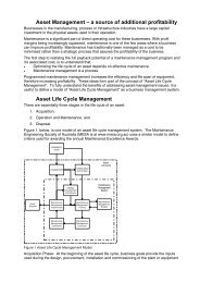
Report Format: The diagnostic report (figure 2) contains a variety of useful information which will be<br />
discussed in this section. In order to facilitate the description, the contents of the report will be described<br />
from top to bottom as they appear in the figure. At top is the machine name (A), followed by the date the<br />
data was acquired and the report run (B) and (C). This is followed by the actual shaft speed as detected by<br />
the data normalization routine (D). In this case, the motor shaft was running at 1191 CPM, and as<br />
mentioned earlier, this is the first calculation made on the data. If the normalization routine failed or the<br />
machine speed was not identified correctly, the rest of the analysis will be invalid.<br />
The machine shaft speed is followed by “Averages: 3” (E). This means that the new data is being compared<br />
to an average + one sigma baseline calculated from 3 separate and prior tests of this machine or tests of<br />
identical machines that an analyst deemed to be representative of the machine in relatively good health.<br />
Average baseline data is not necessary for the bearing wear detection algorithm to be successful but it can<br />
be very useful. If no baseline data is present, new data will be compared to a threshold that can be defined<br />
by the user.<br />
The following line in the report mentions the maximum level detected in all of the data screened from this<br />
machine (F). This information is not relevant to the diagnosis. A repair recommendation (G) follows. This<br />
recommendation is derived from a hierchical rulebase which takes into account the individual faults found<br />
in the machine and their corresponding severities. Although the context of this paper is relegated to the<br />
bearing detection routine, it should be noted that hundreds of other machine faults can be detected by the<br />
system. Thus, if misalignment, unbalance, electrical problems and bearing problems are all reported on a
motor, the recommendation might say “Overhaul Motor” instead of directing the user to balance, align,<br />
replace bearings and check windings.<br />
There are 4 levels of recommendation priorities each relating to different suggested actions. These are “No<br />
Recommendation”, “Desirable”, “Important” and “Mandatory”. These coincide loosely with four levels of<br />
fault severities (H): “Slight”, Moderate”, “Serious”, and “Extreme”. Thus, a “slight motor bearing wear”<br />
fault might result in “No Recommendation” and a “Moderate Motor Bearing Wear” fault might result in<br />
“Desirable: Monitor Motor Bearings for Increased Vibration”. More information on how the severity levels<br />
relate to recommended repair actions can be obtained from <strong>DLI</strong>.<br />
The evidence of the fault (I – M) is displayed below the fault diagnosis (H). These peaks and patterns are<br />
what the diagnostic system has encountered in the data that caused it to report this particular fault. This<br />
allows a human analyst to quickly verify the diagnosis by referring to the spectral plots. Note that it is not<br />
the presence of these peaks alone that caused the diagnosis to be cited, which is to say that this is not a<br />
matter of a simple alarm system. These peaks and others were passed through hundreds of logical rules and<br />
they caused the one cited to become “true”. Definitions of items (I) – (M) as marked in figure 2 follow:<br />
(I)<br />
(J)<br />
(K)<br />
(L)<br />
(M)<br />
Level of Spectral peak<br />
Exceedance of average baseline data (or alarm limit if baseline data is not present)<br />
Units (Note, these could be any engineering units such as in/s, mm/s, g’s, etc.)<br />
Frequency of peak in orders (i.e. multiples of shaft rate)<br />
Measurement location and axis. The measurement location “2” is defined later in the report as<br />
the motor coupled end of the machine. “A” is axial or in the direction of the shaft.<br />
As mentioned in the section titled: “Noise Floor Calculation”, an increase in the noise floor level is an<br />
indication of impacting and non-periodic (or random) vibration. Both of these are associated with later<br />
stage bearing wear. Evidence of an increased noise floor level is displayed in this particular report (N).<br />
Within the particular rule template that was activated in this report, the increase in noise floor level added<br />
to the severity of this fault.<br />
The next section of the report (O) contains an analysis of the demod data and its relationship to the spectral<br />
data. The format of this part of the report is slightly different from the spectral report in that it contains<br />
more text. In this example, the demod part of the report is saying that there is a peak in the demod at 9.33x<br />
that directly matches one of the bearing tone candidates cited in the spectral data. 9.33 is actually the third<br />
harmonic of 3.1x which is the fundamental bearing tone, but 9.33 was evident enough to be extracted from<br />
the normal spectrum as well. Had 9.33 not been extracted, the demod report would have said that there was<br />
a peak at 9.33x that had a harmonic relationship with the spectral data. This would have led to the same<br />
conclusion either way, which is that the demod data supports the diagnosis based on the spectral data.
Example Data<br />
(A) FIRE PUMP #2<br />
(B) Report generated on: 8/19/03 11:07:22 AM<br />
(C) Acquired: 8/19/03 10:35:38 AM (D) 1xM = 1191 RPM (E) Averages: 3<br />
(F) Maximum level: 0.222 (-7) in/s at 3xM on 3T in low range<br />
RECOMMENDATIONS:<br />
(G) MANDATORY: REPLACE MOTOR <strong>BEARING</strong>S<br />
DIAGNOSES:<br />
(H) EXTREME MOTOR <strong>BEARING</strong> <strong>WEAR</strong><br />
(I) (J) (K) (L) (M)<br />
0.056 (+0.042) in/s at 3.11xM on 2A in low range<br />
0.028 (+0.025) in/s at 6.2xM on 2A in low range<br />
0.039 (+0.030) in/s at 9.33xM on 2R in low range<br />
0.079 (+0.077) in/s at 9.33xM on 2T in low range<br />
0.001 (+0.000) in/s at 24.8xM on 2A in high range<br />
0.088 (+0.084) in/s at 3.11xM on 2R in low range<br />
0.022 (+0.021) in/s at 15.5xM on 2R in high range<br />
0.022 (+0.011) in/s at 12.5xM on 2R in high range<br />
0.039 (+0.036) in/s at 3.11xM on 2T in low range<br />
0.022 (+0.019) in/s at 12.5xM on 2T in high range<br />
0.011 (+0.010) in/s at 52.7xM on 2T in high range<br />
0.001 (+0.001) in/s noise floor (N)<br />
0.002 (+0.001) in/s noise floor<br />
0.001 (+0.001) in/s noise floor<br />
(O) MOTOR BALL <strong>BEARING</strong> DEMOD<br />
Bearing tone harmonics in demod spectrum with direct match between<br />
regular and demod spectrum in 2R<br />
21 dB peak at 9.33x on 2R<br />
(P) POSITION LEGEND:<br />
POSITION 2 IS: MOTOR 2<br />
POSITION 3 IS: PUMP 3<br />
(Figure 2: Bearing Diagnostic Report)<br />
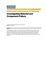
Motor End Spectral Data: In figure 3 below, the X-axis of the graph is labeled in “orders” where “1”<br />
corresponds to 1 times the motor shaft rate. The vertical axis is in inches / second pk.
(Figure 3: Motor Spectral Data – Low Range)<br />
The first item to note when discussing bearing tones is that they frequently appear at frequencies between 3<br />
and 12 times the shaft rate. This is the reason we are looking at a “Low Range” graph with a frequency<br />
range of 0 to 10x the shaft rate in this example. Data collected from 0 to 100x were also collected and used<br />
for this analysis. The data were collected in all three axes on 2 locations on the machine. The second item<br />
to note is that bearing tones rarely show up as integer multiples of the shaft rate. This is to say that they<br />
may show up at 4.6x, 7.2x, 5.8x etc. but rarely at exactly 3x, 4x or 5x. Therefore, after determining the<br />
shaft rate peak (marked “1x”) and its multiples or harmonics (marked 2x, 3x, 4x), we look for peaks that<br />
are not multiples of the shaft rate. These peaks are termed “Non synchronous” and may be bearing tones.<br />
The peak marked with the arrow, towards the left hand side of the graph is at a frequency of 3.1x and is<br />
therefore a good candidate for a bearing tone. The other two peaks marked with arrows are at 6.2x and<br />
9.3x. These are harmonics (multiples) of the tone at 3.1x. Please note that these are the peaks that are cited<br />
on the report in figure 2 above.<br />
Note now the peaks marked with ball point arrows. These peaks are at 4.1x and 5.1x. and are called “1X<br />
Sidebands”, which are common in bearings. These peaks are caused by an effect termed “amplitude<br />
modulation”. Basically, if one has a fault on the inner race of the bearing, this fault rotates in and out of the<br />
load zone, and balls hitting the fault hit it harder in the load zone and softer out of the load zone. To<br />
complete 1 cycle of this increase and decrease, the shaft need turn 1 revolution, and it is this cycle time that<br />
determines the distance between the sidebands. This is why they are separated by a distance of 1X on either<br />
side of the tone at 3.1x.<br />
The automated diagnostic system extracted the two highest non-synchronous peaks from this spectrum<br />
(3.1x and 9.3x). Then Cepstrum analysis was used to see if either of these are part of a harmonic series –<br />
which they are.<br />
Demodulation: Demodulation data were also collected on this machine and are displayed in figure 4<br />
below. Here we can also see a peak at 3.1x (the left most peak marked with an arrow) and harmonics. Even
though 3.1x is the fundamental bearing tone frequency, for some reason, 9.3x is the highest peak in the<br />
demod data and was therefore extracted first. In section “O” of the report, we see this peak at 9.3x cited by<br />
the diagnostic system. The report also mentions that there was a direct match between the demod and the<br />
spectral data. This is to say that the peak at 9.3X was also found in the spectral bearing routine and it<br />
coincides with the peak found in the demod. Thus we have further confirmation that this is in fact a bearing<br />
problem on the motor end of the machine.<br />
Note that the shaft related peaks (1x, 2x, 3x etc.) are filtered out of the demodulated spectrum and only the<br />
bearing tones remain. The demodulation or enveloping technique is quite good at filtering out machine<br />
noise and zooming in on the little clicks made by a ball passing a fault on a race. Because demodulation is<br />
discussed in detail in a variety of other papers available from <strong>DLI</strong> Engineering, we will leave the discussion<br />
here.<br />
(Figure 4: Motor Demodulation Data)<br />
Summary of Example: In diagnosing a bearing problem in this motor, the automated diagnostic system<br />
first began by identifying the motor shaft rate peak and its harmonics via a data normalization routine. The<br />
results of this are found in the report (D). The system then extracted the defined forcing frequencies from<br />
the machine and peaks related to these via a peak extraction routine, followed by the two highest nondefined<br />
peaks in each of the spectra. These 2 next highest peaks were found at 3.1x and 9.3x, and these<br />
peaks were considered bearing tone candidates. A noise floor calculation was also made and stored at this<br />
point.<br />
Cepstrum analysis was then performed to extract families of peaks from the spectra. These families of<br />
peaks are then compared to the possible bearing tones extracted from the spectrum to look for matches. In<br />
this example, it was determined that the peaks at 3.1x and 9.3x are part of a larger family of peaks
including harmonics and sidebands. It is apparent from the spectral graph that these peaks are in fact part of<br />
a larger family of peaks (marked with arrows). The Cepstrum routine simply allows the system to<br />
determine this automatically.<br />
The demodulation algorithm was then run to compare demod spectra to the peaks found in the unfiltered<br />
spectra. The conclusion in this case was that there was a direct correlation between the demod data and the<br />
spectral data, adding confidence to any eventual bearing wear diagnosis.<br />
The extracted peaks and demod information were then sent through all of the applicable rules for this<br />
machine type. If the machine did not have rolling element bearings for example, rolling element bearing<br />
rules would not be applied to this machine. Based on the information sent to the rule base, one of the<br />
several rules for bearing wear “passed” and thus the fault appeared in the report (H) with a corresponding<br />
severity as well as evidence supporting the diagnosis (I – N). Finally, a recommendation with a<br />
corresponding severity (G) was provided based on the faults that were diagnosed in the machine.<br />
Conclusion: The algorithms described in this paper have been in use commercially for well over 15 years<br />
with great success. In minutes, the bearing wear diagnostic system can sort through hundreds of machine<br />
tests that would take an analyst several days to review manually. The fact that the system does not rely on<br />
bearing make or model makes it both easier to configure and more accurate in its diagnosis. If you would<br />
like to learn more about this automated diagnostic system, additional information can be found at<br />
www.<strong>DLI</strong>engineering.com .<br />
About the author:<br />
In 12 years at <strong>DLI</strong> Engineering, <strong>Alan</strong> <strong>Friedman</strong> has worked in software development, expert system<br />
development, data analysis, training, and installation of predictive maintenance programs. He is a<br />
graduate of Tufts University with a B.S. in mechanical engineering.