XAP GWARE 102 Shure MX392 Installation and Configuration ...
XAP GWARE 102 Shure MX392 Installation and Configuration ...
XAP GWARE 102 Shure MX392 Installation and Configuration ...

You also want an ePaper? Increase the reach of your titles
YUMPU automatically turns print PDFs into web optimized ePapers that Google loves.
<strong>XAP</strong> <strong>GWARE</strong> <strong>102</strong><br />
<strong>Shure</strong> <strong>MX392</strong> <strong>Installation</strong> <strong>and</strong> <strong>Configuration</strong><br />
Description<br />
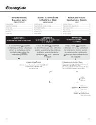
The <strong>Shure</strong> <strong>MX392</strong> is a tabletop boundary microphone designed to work with logic <strong>and</strong> control wiring to<br />
control external devices. The microphone has a switching membrane <strong>and</strong> DIP switches to program the<br />
microphone functionality. This document is an explanation of the correct way to interface the <strong>Shure</strong><br />
MX932 to allow the microphone to control the muting functions on a <strong>XAP</strong> conferencing system.<br />
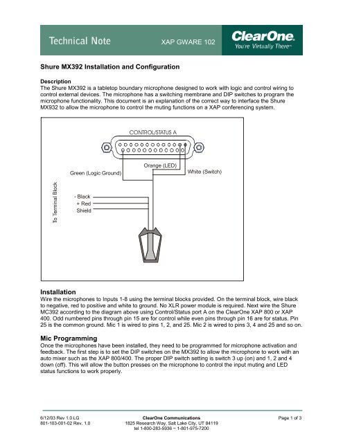
CONTROL/STATUS A<br />
Green (Logic Ground)<br />
Orange (LED)<br />
White (Switch)<br />
- Black<br />
+ Red<br />
Shield<br />
<strong>Installation</strong><br />
Wire the microphones to Inputs 1-8 using the terminal blocks provided. On the terminal block, wire black<br />
to negative, red to positive <strong>and</strong> white to ground. No XLR power module is required. Next wire the <strong>Shure</strong><br />
MC392 according to the diagram above using Control/Status port A on the ClearOne <strong>XAP</strong> 800 or <strong>XAP</strong><br />
400. Odd numbered pins through pin 15 are for control while even pins through pin 16 are for status. Pin<br />
25 is the common ground. Mic 1 is wired to pins 1, 2, <strong>and</strong> 25. Mic 2 is wired to pins 3, 4 <strong>and</strong> 25 <strong>and</strong> so on.<br />
Mic Programming<br />
Once the microphones have been installed, they need to be programmed for microphone activation <strong>and</strong><br />
feedback. The first step is to set the DIP switches on the <strong>MX392</strong> to allow the microphone to work with an<br />
auto mixer such as the <strong>XAP</strong> 800/400. The proper DIP switch setting is switch 3 up (on) <strong>and</strong> 1, 2 <strong>and</strong> 4<br />
down (off). This will allow the button presses on the microphone to control the input muting <strong>and</strong> LED<br />
status functions to work properly.<br />
6/12/03 Rev 1.0 LG ClearOne Communications Page 1 of 3<br />
801-103-001-02 Rev. 1.0 1825 Research Way, Salt Lake City, UT 84119<br />
tel 1-800-283-5936 ~ 1-801-975-7200
<strong>XAP</strong> <strong>GWARE</strong> <strong>102</strong><br />
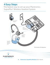
Push to Talk, Push to Mute Control/Status Pin Programming<br />
Control <strong>and</strong> Status pin programming for the <strong>XAP</strong> product is done using the GPIO Builder in G-Ware.<br />
For a microphone that will be functioning as Push to Talk, Push to Mute, program the control pins with an<br />
active (low) comm<strong>and</strong> of # .. Mute 1 M 2. There is no need to set up an inactive (high) comm<strong>and</strong>.<br />
The status pin for the microphone LED is programmed with the active (low) comm<strong>and</strong> of # .. Mute 1 M 1<br />
<strong>and</strong> the inactive (high) comm<strong>and</strong> of # .. Mute 1 M 0. This will allow the LED to follow the mute state of the<br />
microphone. For example, when the mic is muted the LED will be lit <strong>and</strong> when the mic is unmuted, the<br />
LED will not be lit.<br />
6/12/03 Rev 1.0 LG ClearOne Communications Page 2 of 3<br />
801-103-001-02 Rev. 1.0 1825 Research Way, Salt Lake City, UT 84119<br />
tel 1-800-283-5936 ~ 1-801-975-7200
<strong>XAP</strong> <strong>GWARE</strong> <strong>102</strong><br />
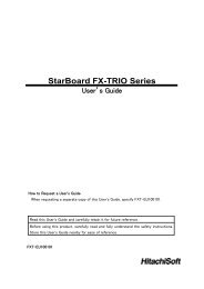
Push to Talk, Release to Mute Control/Status Pin Programming<br />
For a microphone that is Push to Talk, Release to Mute, program the control pins with an active (low)<br />
comm<strong>and</strong> of # .. Mute 1 M 0 to disable the mute <strong>and</strong> an inactive (high) comm<strong>and</strong> of # .. Mute 1 M 1 to<br />
enable the mute.<br />
The status pins will follow the same format for the microphone LED to toggle properly. When the<br />
microphone is unmuted the LED will be off, when the microphone is muted the LED will be on.<br />
6/12/03 Rev 1.0 LG ClearOne Communications Page 3 of 3<br />
801-103-001-02 Rev. 1.0 1825 Research Way, Salt Lake City, UT 84119<br />
tel 1-800-283-5936 ~ 1-801-975-7200