AVerVision SPB370 User Manual
AVerVision SPB370 User Manual
AVerVision SPB370 User Manual

Create successful ePaper yourself
Turn your PDF publications into a flip-book with our unique Google optimized e-Paper software.
FCC NOTICE (Class A)<br />
This device complies with Part 15 of the FCC Rules. Operation is subject to the<br />
following two conditions: (1) this device may not cause harmful interference, and<br />
(2) this device must accept any interference received, including interference that<br />
may cause undesired operation.<br />
Federal Communications Commission Statement<br />
NOTE- This equipment has been tested and found to comply with the limits for a Class A<br />
digital device, pursuant to Part 15 of the FCC Rules. These limits are designed to provide<br />
reasonable protection against harmful interference in a residential installation. This<br />
equipment generates uses and can radiate radio frequency energy and, if not installed<br />
and used in accordance with the instructions, may cause harmful interference to radio<br />
communications. However, there is no guarantee that interference will not occur in a<br />
particular installation. If this equipment does cause harmful interference to radio or<br />
television reception, which can be determined by tuning the equipment off and on, the<br />
user is encouraged to try to correct the interference by one or more of the following<br />
measures:<br />
Reorient or relocate the receiving antenna.<br />
Increase the separation between the equipment and receiver.<br />
Connect the equipment into an outlet on a circuit different from that to which the<br />
receiver is connected.<br />
Consult the dealer or an experienced radio/television technician for help.<br />
Class A ITE:<br />
Class A ITE is a category of all other ITE which satisfies the class A ITE limits but not the<br />
class B ITE limits. Such equipment should not be restricted in its sale but the following<br />
warning shall be included in the instructions for use:<br />
Warning - This is a class A product. In a domestic environment this product may cause<br />
radio interference in which case the user may be required to take adequate measures.<br />
CE Class A (EMC)<br />
This product is herewith confirmed to comply with the requirements set out in<br />
the Council Directives on the Approximation of the laws of the Member States<br />
relating to Electromagnetic Compatibility Directive 2004/108/EEC.<br />
Warning - This is a Class A product. In a domestic environment this product may cause<br />
radio interference in which case the user may be required to take adequate measures to<br />
correct this interference.<br />
DISCLAIMER<br />
No warranty or representation, either expressed or implied, is made with respect to the<br />
contents of this documentation, its quality, performance, merchantability, or fitness for a<br />
particular purpose. Information presented in this documentation has been carefully<br />
checked for reliability; however, no responsibility is assumed for inaccuracies. The<br />
information contained in this documentation is subject to change without notice.<br />
In no event will AVerMedia be liable for direct, indirect, special, incidental, or<br />
consequential damages arising out of the use or inability to use this product or<br />
documentation, even if advised of the possibility of such damages.<br />
TRADEMARKS<br />
<strong>AVerVision</strong> is registered trademarks of AVerMedia Information, Inc. IBM PC is a<br />
registered trademark of International Business Machines Corporation. Macintosh is a<br />
registered trademark of Apple Computer, Inc. Microsoft is a registered trademark and<br />
Windows is a trademark of Microsoft Corporation. All other products or corporate names<br />
mentioned in this documentation are for identification and explanation purposes only, and<br />
may be trademarks or registered trademarks of their respective owners.<br />
COPYRIGHT<br />
© 2008 by AVerMedia Information, Inc. All rights reserved. No part of this publication may<br />
be reproduced, transmitted, transcribed, stored in a retrieval system, or translated into<br />
any language in any form by any means without the written permission of AVerMedia<br />
INFORMATION, Inc.<br />
THE MARK OF CROSSED-OUT WHEELED BIN INDICATES THAT THIS<br />
PRODUCT MUST NOT BE DISPOSED OF WITH YOUR OTHER<br />
HOUSEHOLD WASTE. INSTEAD, YOU NEED TO DISPOSE OF THE<br />
WASTE EQUIPMENT BY HANDING IT OVER TO A DESIGNATED<br />
COLLECTION POINT FOR THE RECYCLING OF WASTE ELECTRICAL<br />
AND ELECTRONIC EQUIPMENT. FOR MORE INFORMATION ABOUT<br />
WHERE TO DROP OFF YOUR WASTE EQUIPMENT FOR RECYCLING,<br />
PLEASE CONTACT YOUR HOUSEHOLD WASTE DISPOSAL SERVICE OR<br />
THE SHOP WHERE YOU PURCHASED THE PRODUCT.
Remote Control Battery Safety Information<br />
- Store batteries in any cool & dry place.<br />
- Do not dispose used batteries in domestic waste. Dispose batteries at special<br />
collection points or return to stores if applies.<br />
- Remove the batteries if they are not in use for long period of time. Battery<br />
leakage and corrosion can damage the remote control, dispose batteries safely.<br />
- Do not mix and use old and new batteries.<br />
- Do not mix and use different types of batteries: alkaline, standard (carbon-zinc)<br />
or rechargeable (nickel-cadmium).<br />
- Do not dispose batteries in a fire.<br />
- Do not attempt to short circuit the battery terminals.<br />
Remote Control Class 2 Laser Product<br />
LASER RADIATION<br />
DO NOT STARE INTO THE BEAM<br />
CLASS 2 LASER PRODUCT
Table of Contents<br />
Introduction .................................................................................... 1<br />
Package Contents ........................................................................... 1<br />
Optional Accessories ...................................................................... 1<br />
AVerMedia® <strong>AVerVision</strong> <strong>SPB370</strong> Parts ............................................ 2<br />
Making the Connections.................................................................. 3<br />
Rear Panel........................................................................................................ 3<br />
Left Panel.......................................................................................................... 3<br />
Right Panel ....................................................................................................... 4<br />
Connecting a VGA, Mac Monitor or LCD/DLP Projector.................................. 4<br />
Connecting a Monitor or LCD/DLP Projector with DVI interface ...................... 5<br />
Connecting a TV............................................................................................... 5<br />
Connecting the Power Adapter......................................................................... 6<br />
Connecting a Computer.................................................................................... 6<br />
Connecting a Microphone................................................................................. 6<br />
Connecting to Audio Output Device ................................................................. 7<br />
Connecting a Computer via USB Connection .................................................. 7<br />
Inserting and Ejecting a SD Card ..................................................................... 8<br />
Setting Up <strong>SPB370</strong> .......................................................................... 8<br />
Arm ................................................................................................................... 8<br />
Camera Head ................................................................................................... 8<br />
Overhead Light ................................................................................................. 9<br />
Infrared Sensor ................................................................................................. 9<br />
Light Box........................................................................................................... 9<br />
Anti-glare .......................................................................................................... 9<br />
Microscope Connection .................................................................................. 10<br />
Control Panel Light Color ............................................................................... 10<br />
Using Web Browser to Control <strong>SPB370</strong>.......................................... 10<br />
Using the Infrared Remote Control................................................. 11<br />
Touch Button Control Panel .......................................................... 13<br />
Using <strong>AVerVision</strong> <strong>SPB370</strong> as a Mass Storage ................................ 14<br />
OSD Navigation Tree ..................................................................... 15<br />
Menu Functions ............................................................................ 16<br />
Technical Specifications................................................................ 19<br />
RS-232C Diagram Connection ....................................................... 20<br />
RS-232C Cable Spec...................................................................... 20<br />
RS-232C Transmission Spec ......................................................... 20<br />
RS-232C Communication Format................................................... 20<br />
Send Command Format ................................................................................. 20<br />
Set Value Format............................................................................................ 21<br />
Get Value Format ........................................................................................... 22<br />
Troubleshooting............................................................................ 22<br />
Limited Warranty....................................................................... 23
Introduction<br />
Thank you for purchasing<br />
the AVerMedia ®<br />
<strong>AVerVision</strong> <strong>SPB370</strong>. This<br />
document camera<br />
displays documents,<br />
negatives, transparencies<br />
and 3D objects onto a TV,<br />
LCD or DLP projector<br />
making demonstrations a<br />
snap.<br />
The advanced features of<br />
the <strong>AVerVision</strong> <strong>SPB370</strong><br />
make it a versatile and<br />
multi-functional product.<br />
Integrated with the new<br />
powerful zoom feature,<br />
AVEROPTICAL Zoom is a<br />
combination of optical<br />
zoom with AVERZOOM.<br />
AVERZOOM is an<br />
AVerMedia patented<br />
technology which digitally<br />
zooms in and pans on an<br />
image while maintaining<br />
optical zoom image<br />
quality. You can save still<br />
images in the built-in<br />
memory, or SD memory<br />
card. When connected to<br />
a computer via USB<br />
connection and with the<br />
bundled software, you can<br />
capture and save still<br />
images and video clips to<br />
your hard drive directly. It<br />
also comes with a fullyfeatured<br />
remote control.<br />
Package Contents<br />
Your AVerMedia ® <strong>AVerVision</strong> <strong>SPB370</strong> package contains the following:<br />
AVerMedia ® <strong>AVerVision</strong> <strong>SPB370</strong><br />
DUST COVER<br />
Dust Cover<br />
Anti-glare Sheet<br />
Remote Control<br />
(batteries included)<br />
<strong>User</strong> <strong>Manual</strong><br />
Installation CD<br />
RCA Cable (2X)<br />
Power Adapter<br />
S-Video Cable<br />
Power Cord<br />
* The power cord varies depending on the<br />
standard power outlet of the country where it is<br />
sold.<br />
RGB Cable<br />
USB Cable<br />
Optional Accessories<br />
34mm Microscopic<br />
Adapter<br />
28mm Microscopic<br />
Adapter<br />
1
RGB IN 2<br />
RGB IN 1<br />
RS-2 32<br />
IO IO I<br />
IOIOI<br />
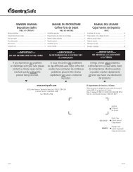
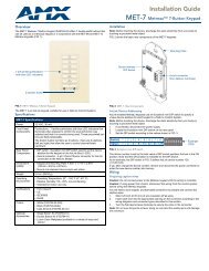
1. Overhead light<br />
2. Camera head<br />
3. Camera lens<br />
4. Left panel<br />
5. Control panel<br />
6. Light box<br />
7. Arm<br />
8. Label slot<br />
9. IR sensors<br />
10. Rear panel<br />
11. Right panel<br />
12. MIC IN port<br />
13. Video output switch<br />
14. Light box power<br />
button<br />
15. DC 12V port<br />
16. RGB output port<br />
17. S-Video output port<br />
18. Video output port<br />
(RCA/Composite)<br />
19. DVI-I output port<br />
20. USB port<br />
21. SD card slot<br />
22. RGB IN 1 port<br />
23. RGB IN 2 port<br />
24. Audio out port<br />
25. RS-232 port<br />
26. Ethernet (RJ-45) port<br />
27. Antitheft slot<br />
AVerMedia® <strong>AVerVision</strong> <strong>SPB370</strong> Parts<br />
The illustrations below identify the parts of <strong>SPB370</strong>.<br />
(1)<br />
(2)<br />
(3)<br />
(4)<br />
(5)<br />
(6)<br />
Left Panel (12)<br />
MIC IN VIDEO OUTPUT LIGHT BOX<br />
TV RGB<br />
(13)<br />
(14)<br />
AUDIO OU T<br />
ET HERNE T<br />
(7)<br />
(8)<br />
(9)<br />
(10)<br />
(11)<br />
MIC IN<br />
VIDEO OUTPU T<br />
LIGHT BOX<br />
<strong>SPB370</strong><br />
TV<br />
RGB<br />
Rear Pane l<br />
DC 12V<br />
RGB<br />
OUTPUT<br />
S-VIDEO VIDEO<br />
OUTPUT OUTPUT<br />
DVI-I OUTPUT USB SD CARD<br />
(15)(16) (17) (18) (19) (20)(21)<br />
Righ t Panel<br />
(22)<br />
(23)<br />
(24)<br />
AUDIO OU T<br />
RGB IN 2<br />
RGB IN 1<br />
RS-232<br />
ETHERNET<br />
(25)<br />
(26)<br />
(27)<br />
IOIOI<br />
AUDIO OUT<br />
RGB IN 2<br />
RGB IN 1<br />
RS-232<br />
ETHERNET<br />
2
Making the Connections<br />
The ports on the rear, left and right panel of <strong>SPB370</strong> enable you to connect the unit to a<br />
computer, graphics display monitor or LCD/DLP projector, TV or other device. Illustrated<br />
below are the ports that are located at the rear and right panel of <strong>SPB370</strong> with their<br />
corresponding labels.<br />
Rear Panel<br />
DC 12V<br />
RGB<br />
OUTPUT<br />
S-VIDEO VIDEO<br />
OUTPUT OUTPUT<br />
DVI-I OUTPUT USB SD CARD<br />
Name<br />
(1) (2) (3) (4) (5) (6) (7)<br />
Function<br />
(1) DC 12V : Connect the power adapter into this port.<br />
(2) RGB output : Output the signal from the camera, RGB IN port, or the<br />
captured images from the memory source on a VGA/Mac<br />
monitor or LCD/DLP projector.<br />
(3) S-Video output : Output the signal from the camera or the captured images<br />
from the memory source on TV or Video equipment.<br />
(4) Video output<br />
(RCA/Composite)<br />
: Output the signal from the camera or the captured images<br />
from the memory source on TV or Video equipment.<br />
(5) DVI-I output : Output the signal from the camera, RGB IN port, or the<br />
captured images from the memory source on a VGA/Mac<br />
monitor or LCD/DLP projector with DVI-I interface. If the<br />
display device does not support DVI-I, it can only display<br />
the signal from the camera and the captured images.<br />
(6) USB : Use <strong>SPB370</strong> as a USB Camera or Mass Storage to<br />
transfer the captured images from <strong>SPB370</strong> memory<br />
source to PC.<br />
(7) SD card : Insert the SD card with the label facing up. It can support<br />
16MB~2GB card capacity and only accepts FAT16<br />
formatted card.<br />
Left Panel<br />
MIC IN<br />
VIDEO OUTPU T<br />
LIGHT BOX<br />
<strong>SPB370</strong><br />
TV<br />
RGB<br />
Name<br />
(1)(2)(3)<br />
Function<br />
1. MIC IN : Connect a Ф 6.3mm jack microphone into this port.<br />
2. VIDEO OUTPUT : Select to output video signal between RGB (RGB & DVI-I)<br />
or TV (Composite Video/S-Video) display output.<br />
3. LIGHT BOX : Turn on/off the light box.<br />
3
DC 12V<br />
RGB<br />
OUTPUT<br />
S-VIDEO<br />
OUTPUT<br />
VIDEO<br />
OUTPUT<br />
DVI-I OUTPUT USB SD CARD<br />
IOIOI<br />
Right Panel<br />
AUDIO OUT<br />
RGB IN 2<br />
RGB IN 1<br />
RS-232<br />
ETHERNET<br />
Name<br />
Function<br />
(1) (2) (3)(4) (5)<br />
(1) Audio Out : Output the microphone audio signal to an amplifier, on TV, or<br />
AV equipment audio input port. Or, Use an RCA Jack to 3.5mm<br />
Mono Plug Adapter to connect to computer line-in port.<br />
(2) RGB IN 1 &<br />
RGB IN 2<br />
: Takes as input the signal from a computer or other sources<br />
and pass it through to the RGB Output and DVI-I port only.<br />
Connect this port to the VGA output port of the computer.<br />
(3) RS-232 : Receive command from the computer to operate <strong>SPB370</strong>.<br />
Connect this port to the RS-232 port of the computer.<br />
(4) Ethernet : Use an RJ-45 Ethernet cable and connect it to RJ-45 Ethernet<br />
port. This connection allows using any Web browser to access<br />
the embedded web server and remotely control <strong>SPB370</strong>. Make<br />
sure <strong>SPB370</strong> is connected to IP-based network. Also see<br />
“Using Web Browser to Control <strong>SPB370</strong>”.<br />
(5) Antitheft slot : Attach a Kensington compatible security lock or antitheft<br />
device.<br />
Connecting a VGA, Mac Monitor or LCD/DLP Projector<br />
Locate the RGB (VGA) input port of the display device and connect it to RGB OUTPUT port<br />
of <strong>SPB370</strong>.<br />
Make sure the Video Output switch is set to RGB.<br />
RGB cable<br />
LCD/DLP projector<br />
CRT monitor<br />
MAC<br />
Monitor Adapter<br />
(not supplied)<br />
MAC monitor<br />
LCD monitor<br />
4
DC 12V<br />
DC 12V<br />
RGB<br />
OUTPUT<br />
RGB<br />
OUTPUT<br />
S-VIDEO<br />
OUTPUT<br />
S-VIDEO<br />
OUTPUT<br />
VIDEO<br />
OUTPUT<br />
VIDEO<br />
OUTPUT<br />
DVI-I OUTPUT USB SD CARD<br />
DVI-I OUTPUT USB SD CARD<br />
Connecting a Monitor or LCD/DLP Projector with DVI<br />
interface<br />
Locate the DVI input port of the display device and connect it to DVI-I OUTPUT port of<br />
<strong>SPB370</strong>.<br />
Make sure the Video Output switch is set to RGB.<br />
LCD Monitor<br />
with DVI interface<br />
DVI cable<br />
(not supplied)<br />
LCD/DLP projector<br />
with DVI interface<br />
Connecting a TV<br />
Locate the VIDEO (yellow), S-VIDEO or SCART RGB input port of the TV or Video<br />
equipment (i.e., VCR) to record your presentation on a videotape and connect it to S-VIDEO<br />
or VIDEO OUTPUT port of <strong>SPB370</strong>.<br />
- Make sure the Video Output switch is set to TV.<br />
- For better video quality, we strongly suggest using S-VIDEO connection.<br />
I N P U T<br />
RCA to SCART cable<br />
(not supplied)<br />
SCART<br />
RCA cable<br />
VIDEO<br />
P r o j e c t o r<br />
S-Video cable<br />
S-VIDEO<br />
S-Video to SCART cable<br />
(not supplied)<br />
SCART<br />
Te l e v i s i o n<br />
V C R<br />
5
MIC IN<br />
VIDEO OUTPUT<br />
TV<br />
RGB<br />
DC 12V<br />
LIGHT BOX<br />
RGB<br />
OUTPUT<br />
S-VIDEO<br />
OUTPUT<br />
VIDEO<br />
OUTPUT<br />
DVI-I OUTPUT USB SD CARD<br />
IOIOI<br />
Connecting the Power Adapter<br />
Connect the power adapter to a standard 100V~240V AC power source.<br />
Wall outlet<br />
Power adapter<br />
Power cord<br />
Connecting a Computer<br />
Locate the RGB (VGA) output port of the computer or laptop to display your PC presentation<br />
on screen and connect it to RGB IN 1 or RGB IN 2 ports of <strong>SPB370</strong>. The video signal from<br />
the RGB INPUT port is streamed to RGB and DVI-I OUTPUT ports only, and displayed on<br />
the screen even in stand-by mode. Press SOURCE button on the control panel or remote to<br />
switch to PC-1 or PC-2.<br />
Computer<br />
Laptop<br />
RGB cable<br />
MAC<br />
Monitor Adapter<br />
(not supplied)<br />
Connecting a Microphone<br />
Plug a Ф 6.3mm jack Microphone to MIC IN port.<br />
<strong>SPB370</strong><br />
M i c r o p h o n e<br />
( n o t s u p p l i e d )<br />
6
DC 12V<br />
RGB<br />
OUTPUT<br />
S-VIDEO<br />
OUTPUT<br />
VIDEO<br />
OUTPUT<br />
DVI-I OUTPUT USB SD CARD<br />
IOIOI<br />
Connecting to Audio Output Device<br />
Locate the audio input port (red/white) of the Audio Output device and connect it to AUDIO<br />
OUT port of <strong>SPB370</strong>. For computer, use an RCA Jack To 3.5mm Mono Plug Adapter and<br />
connect it to Line-in port (blue) with this symbol or Mic In port.<br />
I NPUT<br />
Te l e v i s i o n<br />
V C R<br />
AUDIO<br />
RCA cable<br />
S t e r e o<br />
Desktop<br />
Laptop<br />
RCA Jack to 3.5mm<br />
Mono Plug Adapter<br />
(not supplied)<br />
RCA cable<br />
Connecting a Computer via USB Connection<br />
Locate the USB port of the computer or laptop and connect it to USB port of <strong>SPB370</strong>. This<br />
enables you to use <strong>SPB370</strong> as a USB Camera and to transfer the captured images from the<br />
memory source and to computer. Also see “Using <strong>AVerVision</strong> <strong>SPB370</strong> as a Mass Storage”.<br />
Computer<br />
Laptop<br />
USB cable<br />
MAC<br />
7
V IDEO OUTPU T<br />
TV<br />
RGB<br />
LIGHT BOX<br />
VIDEO OUTP UT<br />
TV<br />
RGB<br />
LIGHT BOX<br />
SPB350<br />
RGB<br />
LIGHT BOX<br />
90° 90°<br />
SP B350<br />
Inserting and Ejecting a SD Card<br />
Insert the card with the label facing up until it reaches the end. To remove, pull the card out.<br />
The supported SD card capacity is from 16MB to 2GB. Make sure the card is formatted to<br />
FAT16. <strong>SPB370</strong> automatically creates and stores the images in AVERJPG folder.<br />
Setting Up <strong>SPB370</strong><br />
S D c a r d<br />
( n o t s u p p l i e d )<br />
This section provides useful tips on how to adjust the <strong>SPB370</strong> to meet your needs.<br />
Arm<br />
The arm must be unfolded fully in upright position.<br />
90°<br />
Correct Operating Position<br />
Wrong Operating Position<br />
90°<br />
SPB350<br />
Camera Head<br />
The camera head can be folded up 90° and turned 90° to the left and right. To display an<br />
object more than 50cm away from the camera, unscrew the close-up lens. Do not forget to<br />
screw back the close-up lens afterwards.<br />
90°<br />
50cm<br />
8
MIC IN<br />
V IDE O OUTPUT<br />
TV<br />
RGB<br />
LIGHT B OX<br />
8Kg (+ )<br />
Overhead Light<br />
Press LAMP button on the control panel to turn on and off light.<br />
90°<br />
<strong>SPB370</strong><br />
Infrared Sensor<br />
Aim the remote control at the infrared sensors to operate the unit.<br />
Light Box<br />
Press LIGHT BOX button on the left panel of <strong>SPB370</strong> to turn on and off light. Use this to<br />
view negatives film, x-rays, and 35mm slides.<br />
: DO NOT place an object weighing more than 8kg on top of the light box.<br />
light weight object<br />
photos<br />
negative film<br />
document<br />
Light Box Button<br />
Anti-glare<br />
The anti-glare sheet is a special coated film that helps eliminate any glare that may be<br />
encountered while displaying very shiny objects or glossy surfaces such as magazines and<br />
pictures. To use, simply place the anti-glare sheet on top of the shiny document to reduce<br />
reflected light.<br />
9
AUDIO OUT<br />
RGB IN 2<br />
RGB IN 1<br />
RS-232<br />
IOIOI<br />
ETHERNET<br />
Microscope Connection<br />
Connecting the <strong>SPB370</strong> to a microscope enables you to examine microscopic objects on a<br />
big screen without straining your eyes.<br />
1. Change the image display mode to<br />
Microscope. Press MENU > select<br />
SETTING > MODE > MICROSCOPE and<br />
press ENTER.<br />
2. Adjust the microscope focus to its best<br />
clarity. Then, select the appropriate<br />
adapter size that would fit the microscope<br />
eyepiece.<br />
Close-up Lens<br />
3. Unscrew the close-up lens from the<br />
camera head.<br />
4. Remove the microscope eyepiece from<br />
the microscope and connect it to the<br />
microscope adapter. Then, fasten the 3<br />
bolts until the adapter secures the<br />
eyepiece.<br />
Microscope<br />
Adapter<br />
(optional)<br />
Microscope<br />
We suggest using a microscope with<br />
an eye relief of 15.5mm or higher for<br />
better view.<br />
5. Screw the microscope adapter to the<br />
<strong>AVerVision</strong> camera head. Then, connect it<br />
to the microscope.<br />
Control Panel Light Color<br />
The LED power button on the control panel of <strong>SPB370</strong> indicates the status of the unit.<br />
Color<br />
Blue<br />
Orange<br />
Description<br />
: The unit is in operating mode.<br />
: The unit is in standby mode.<br />
Using Web Browser to Control <strong>SPB370</strong><br />
This enables you to remotely control <strong>SPB370</strong> thru any web browser (i.e. Microsoft Internet<br />
Explorer). Make sure <strong>SPB370</strong> is connected to an IP-based network.<br />
To use web browser to control <strong>SPB370</strong>:<br />
1. Use an RJ-45 Ethernet cable and connect it from the Ethernet port of <strong>SPB370</strong> to RJ-45<br />
wall jack or Ethernet hub.<br />
RJ-45 wall jack<br />
RJ-45 Cable<br />
(not supplied)<br />
2. Set the IP, NETMASK and GATEWAY address of <strong>SPB370</strong>.<br />
To set the network address:<br />
Press MENU > select SETTING > ETHERNET and press ENTER. In the ETHERNET<br />
menu, select DHCP and press ► to turn DHCP ON to automatically request for network<br />
address or OFF to manually set the network address.<br />
10
To manually set the network address:<br />
In the ETHERNET menu, use the ▲or▼ buttons to make a<br />
selection and to change value, press ► to enter or to move<br />
to the next digit, and press ENTER to apply the new setting.<br />
Make sure to set the correct address for each setting. For<br />
assistance, contact your network administrator.<br />
ETHERNET<br />
DHCP OFF<br />
IP 010.001.004.016<br />
NETMASK 000.000.000.000<br />
GATEWAY 000.000.000.000<br />
3. Type the IP address of <strong>SPB370</strong> in the web browser. The Web browser will access the<br />
embedded web server and can remotely control <strong>SPB370</strong>. To use the <strong>SPB370</strong> remote<br />
control interface, refer to section “Using the Infrared Remote Control”.<br />
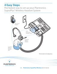
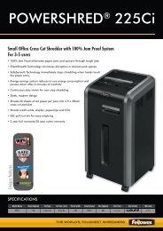
Using the Infrared Remote Control<br />
Use the <strong>SPB370</strong> Remote Control to enhance your presentation by having the ability to switch<br />
between three (3) presentation modes and access various features. To use the remote<br />
control, first insert the batteries (2 “AAA” size batteries are provided) into the battery<br />
compartment at the back of the remote. Use the figure and descriptions below as a reference<br />
for remote control functions.<br />
(13)<br />
(14)<br />
(15)<br />
(16)<br />
(17)<br />
(1)<br />
(2)<br />
(3)<br />
(4)<br />
(5)<br />
(6)<br />
(7)<br />
(8)<br />
(9)<br />
(10)<br />
(11)<br />
(12)<br />
Name<br />
11<br />
Function<br />
(1) POWER Turn the unit on/off.<br />
(2) LASER Turn on the laser pointer.<br />
(3) Shuttle<br />
Wheel<br />
DO NOT look directly at the laser pointer and avoid<br />
aiming the laser at any surface that may reflect the<br />
beam (i.e., a mirror or mirrored surface).<br />
- Turn the shuttle wheel clockwise to<br />
zoom in and counter-clockwise to zoom<br />
out the image optically and digitally in<br />
Camera and Playback mode only.<br />
When it exceeds the maximum optical<br />
zoom level of about 8X, you may still<br />
continue to AVEROPTICAL zoom up to<br />
2.5X AVerZoom and 8X digitally zoom.<br />
Press ENTER to return to normal view<br />
(100%). The zoom bar indicator will turn<br />
from blue to aqua to indicate that you<br />
can pan around the image.<br />
- Press the shuttle wheel ▲,▼,◄, & ► to<br />
pan the image while in digital zoom<br />
mode, to make a selection on 16-<br />
thumbnail images or move to the next or<br />
previous single full screen preview in<br />
Playback mode, or to make a selection<br />
or adjustment on the OSD main-menu<br />
and sub-menu (See Menu Functions for<br />
more details).
Name<br />
Function<br />
(4) ENTER Make a selection in Playback mode and OSD menu. Use this to quick zoom<br />
to 200% or back to 100% in Camera mode only.<br />
(5) AF (Auto Focus) Adjust the focus automatically.<br />
(6) Source Switch between Camera, Playback, PC mode.<br />
- Camera mode displays the video signal from the built-in camera.<br />
- Playback mode displays the captured image from the memory source in<br />
16-thumbnail images. Use ▲,▼,◄, & ► buttons or rotate the shuttle<br />
wheel to make a selection and ENTER to display the selected image in full<br />
screen.<br />
Press MENU to display the Playback menu. Select SLIDE SHOW to start<br />
or set the time interval between frames in second, MEMORY SOURCE to<br />
select the image location between the built-in memory or SD card, and<br />
DELETE to permanently remove the selected image from the selected<br />
memory source.<br />
- PC mode displays the video signal from the RGB IN 1 and RGB IN 2 port<br />
of <strong>SPB370</strong>. It will first display the signal from RGB IN 1. To display the<br />
signal from RGB IN 2, press the SOURCE button again. The PC LED light<br />
will remain on when it is in PC 1 and PC2.<br />
(7) CAP/DEL - Capture a still image in Camera mode. The captured image is saved in the<br />
selected memory source at 1600 x 1200 resolution and the built-in memory<br />
can store up to 80 images.<br />
- Remove the selected picture from the selected memory source<br />
permanently in Playback mode.<br />
(8) ROTATE Turn the image by 90°in Camera mode and 180 in full screen Playback mode.<br />
(9) TIMER Display the OSD timer menu and use ▲or▼ buttons to select SET TIME to<br />
set the time value, START to begin the countdown timer, PAUSE/RESUME<br />
to temporarily halt or continue, and STOP to end. Press MENU to hide the<br />
timer menu.<br />
(10) PROFILE Recall and switch from the 3 saved user setting profile selections (See MENU<br />
Functions – SAVE for more details).<br />
(11) PIP Display/hide a thumbnail of the captured image from the memory source at<br />
the corner of the screen while in Camera mode.<br />
Use ◄ or ► buttons to move to the previous or next image and ENTER to<br />
display the image in full screen. To move the mini playback screen to different<br />
corners, press MENU, go to PIP and select the position of the mini playback<br />
screen.<br />
(12) PRESENTER Select to turn on/off AVerBox or AVerVisor. Only one feature can be used at<br />
a time.<br />
AVerBox overlays a frame on the presentation<br />
screen. Selecting SHADE changes the opacity of<br />
the area outside the box from 0%, 50% and 100%,<br />
COLOR to change the frame color from red, green<br />
and blue, and RESIZE to change the size of the<br />
frame. To resize or move the frame around the<br />
presentation screen, press the shuttle wheel<br />
▲,▼,◄, & ►.<br />
AVerVisor covers part of the presentation<br />
screen. The upper part of the presentation<br />
screen is slightly exposed when it is being<br />
called each time. To expose part of the covered<br />
area, press the shuttle wheel ▲,▼,◄, &►.<br />
Select SHADE to change the darkness of the<br />
shaded area between 50% or 100%.<br />
(13) MENU Pull up and exit the OSD main-menu and sub-menu.<br />
(14) AUTO IMAGE Automatically adjust and set the white balance and exposure setting.<br />
(15) FREEZE Toggle to pause or resume the camera.<br />
12
Name<br />
Function<br />
(16) EFFECT Convert and display the image in BW, Negative or Color in Camera and<br />
Playback mode only.<br />
(17) SPLIT SCRN Turn on/off split screen mode. Split Screen divides the screen into two parts.<br />
One side displays the live image from the <strong>SPB370</strong> camera and the other side<br />
displays the captured images from the memory source in 8-thumbnail<br />
preview.<br />
Use the ▲,▼,◄, &► buttons to make a selection and ENTER to enlarge the<br />
selected image in split screen mode. To horizontally or vertically pan the<br />
enlarged image, use the ◄ & ► or ▲&▼ buttons. To switch to different split<br />
screen type, press MENU, go to SPLIT SCREEN and select between vertical<br />
or horizontal splitting type.<br />
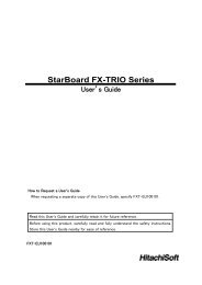
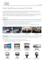
Touch Button Control Panel<br />
The touch button control panel located on the top side of <strong>AVerVision</strong> <strong>SPB370</strong> provides quick<br />
access to commonly used functions.<br />
(1) (2) (3) (4) (5) (6) (7) (8)<br />
POWER<br />
SOURCE<br />
MENU<br />
AUTO IMAGE<br />
CAP/DEL<br />
RGB<br />
CAMERA<br />
FREEZE<br />
ROTATE<br />
TV<br />
PLAYBACK<br />
PC<br />
LAMP<br />
AUTO FOCUS<br />
BRIGHTNESS<br />
(14)<br />
(13) (12) (11)<br />
(10) (9)<br />
Name<br />
Function<br />
(1) POWER Turn the unit on/off.<br />
(2) SOURCE Switch between Camera, Playback, PC mode.<br />
- Camera mode displays the video signal from the built-in camera.<br />
- Playback mode displays the captured image from the memory<br />
source in 16-thumbnail images. Use ▲,▼,◄, & ► buttons or<br />
rotate the shuttle wheel to make a selection and ENTER to display<br />
the selected image in full screen.<br />
Press MENU to display the Playback menu. Select SLIDE SHOW<br />
to start or set the time interval between frames in second,<br />
MEMORY SOURCE to select the image location between the<br />
built-in memory or SD card, and DELETE to permanently remove<br />
the selected image from the selected memory source.<br />
- PC mode displays the video signal from the RGB IN 1 and RGB IN<br />
2 port of <strong>SPB370</strong>. It will first display the signal from RGB IN 1. To<br />
display the signal from RGB IN 2, press the SOURCE button<br />
again. The PC LED light will remain on when it is in PC 1 and PC2.<br />
(3) MENU Pull up and exit the OSD main-menu and sub-menu.<br />
(4) ENTER Make a selection in Playback mode and OSD menu.<br />
(5) AUTO IMAGE Automatically adjust and set the white balance and exposure setting.<br />
(6) FREEZE Toggle to pause or resume the camera.<br />
(7) CAP/DEL - Capture a still image in Camera mode. The captured image is<br />
saved in the selected memory source at 1600 x 1200 resolution<br />
and the built-in memory can store up to 80 images.<br />
- Remove the selected picture from the selected memory source<br />
permanently in Playback mode.<br />
13
Name<br />
Function<br />
(8) ROTATE Turn the image by 90°in Camera mode and 180 in full screen<br />
Playback mode.<br />
(9) BRIGHTNESS Adjust the brightness level in Camera mode to improve the visibility.<br />
(10) AUTO FOCUS Adjust the focus automatically.<br />
(11) SHUTTLE<br />
WHEEL<br />
- Turn the shuttle wheel clockwise to zoom in and counter-clockwise<br />
to zoom out the image optically and digitally in Camera and<br />
Playback mode only.<br />
When it exceeds the maximum optical zoom level of about 8X, you<br />
may still continue to AVEROPTICAL zoom up to 2.5X AVerZoom<br />
and 8X digitally zoom. Press ENTER to return to normal view<br />
(100%). The zoom bar indicator will turn from blue to aqua to<br />
indicate that you can pan around the image.<br />
- Press the shuttle wheel ▲,▼,◄, & ► to pan the image while in<br />
digital zoom mode, to make a selection on 16-thumbnail images or<br />
move to the next or previous single full screen preview in Playback<br />
mode, or to make a selection or adjustment on the OSD mainmenu<br />
and sub-menu (See Menu Functions for more details).<br />
(12) LAMP Turn the overhead light on/off.<br />
(13) Source LED<br />
Indicator<br />
(14) Video Output<br />
LED Indicator<br />
Indicate the selected Source mode either in Camera, Playback or<br />
PC.<br />
Indicate the setting of the Video Output switch to which the video<br />
signal is being sent out.<br />
Using <strong>AVerVision</strong> <strong>SPB370</strong> as a Mass Storage<br />
This enables you to transfer the captured image to and from the memory source and PC.<br />
You MUST read and follow the instructions below BEFORE connecting the USB<br />
cable.<br />
Every time when using the <strong>SPB370</strong> as Mass Storage, the following MUST be done:<br />
1. Select the memory source.<br />
To select the memory source, press MENU ><br />
select SETTING > MEMORY > SOURCE ><br />
EMBEDDED or SD and press ENTER; then<br />
press MENU to exit.<br />
2. MUST set the USB CONNECTION as MASS<br />
STORAGE.<br />
To set the USB connection type, press MENU ><br />
select SETTING > USB CONNECTION > MASS<br />
STORAGE and press ENTER; then press<br />
MENU to exit.<br />
3. When “MASS STORAGE” appears at the<br />
lower left corner of the presentation screen,<br />
you may now connect the USB cable (See<br />
“Connecting a Computer via USB Connection”<br />
for illustration).<br />
4. Upon connecting the USB cable, the system automatically detects the new removable<br />
disk.<br />
5. In the Removable Disk dialog box, select Open folder to view files and then click OK.<br />
You may now transfer the file to and from your PC hard disk.<br />
14
OSD Navigation Tree<br />
VIDEO OUTPUT OSD<br />
For TV output, RESOLUTION is not included in the menu list.<br />
PLAYBACK OSD<br />
MENU<br />
SLIDE SHOW<br />
MEMORY SOURCE<br />
DELETE<br />
SLIDE SHOW<br />
START<br />
INTERVAL<br />
EMBEDDED<br />
SD CARD<br />
1<br />
1<br />
10<br />
NO<br />
YES<br />
15
Menu Functions<br />
The MENU functions of <strong>SPB370</strong> enhance fine-tuning your screen display, set the timer,<br />
select OSD language and more. Press the MENU button to call up and exit from the main<br />
menu or sub-menu display. Then use ▲or▼ buttons to select the items in the menu list.<br />
Use ►/ENTER button to enter sub-menu and ◄/ ENTER to return to main menu. To<br />
adjust the setting, press ◄or► buttons. To make a selection, press ENTER.<br />
OSD Menu<br />
MENU<br />
EFFECT<br />
MIRROR<br />
PRESENTER<br />
SPLIT SCREEN<br />
PIP<br />
SETTING<br />
TIMER<br />
CAPTURE<br />
RECALL<br />
DEFAULT<br />
MENU<br />
EFFECT<br />
MIRROR<br />
PRESENTER<br />
SPLIT SCREEN<br />
PIP<br />
SETTING<br />
TIMER<br />
CAPTURE<br />
RECALL<br />
DEFAULT<br />
MENU<br />
EFFECT<br />
MIRROR<br />
PRESENTER<br />
SPLIT SCREEN<br />
PIP<br />
SETTING<br />
TIMER<br />
CAPTURE<br />
RECALL<br />
DEFAULT<br />
COLOR<br />
B / W<br />
NEGATIVE<br />
ON<br />
OFF<br />
AVERBOX OFF<br />
AVERVISOR OFF<br />
SHADE<br />
COLOR<br />
RESIZE<br />
Description<br />
EFFECT<br />
Press ► and use ▲or▼ buttons to select and display the image in<br />
Camera mode into positive (true color), monochrome (black and white) or<br />
negative. Then press ►/ENTER to make a selection.<br />
MIRROR<br />
Press ► and use ▲or▼ buttons to select turning on/off MIRROR to flip<br />
the image in Camera mode. Then press ►/ENTER to make a selection.<br />
PRESENTER<br />
Press ► and use ▲or▼ buttons to select and turn on either AVERBOX or<br />
AVERVISOR. Then press ►/ENTER to make a selection. Only one<br />
feature can be used at a time.<br />
AVerBox overlays a frame on the presentation screen. Selecting SHADE<br />
changes the opacity of the area outside the box from 0%, 50% and 100%,<br />
COLOR to change the frame color from red, green and blue, and RESIZE<br />
to change the size of the frame. To resize or move the frame around the<br />
presentation screen, press the shuttle wheel ▲,▼,◄, & ►.<br />
AVerVisor covers part of the presentation screen. The upper part of the<br />
presentation screen is slightly exposed when it is being called each time.<br />
To expose part of the covered area, press the shuttle wheel ▲,▼,◄, & ►.<br />
Select SHADE to change the darkness of the shaded area between 50%<br />
or 100%.<br />
MENU<br />
EFFECT<br />
MIRROR<br />
PRESENTER<br />
SPLIT SCREEN<br />
PIP<br />
SETTING<br />
TIMER<br />
CAPTURE<br />
RECALL<br />
DEFAULT<br />
VERTICAL<br />
HORIZONTAL<br />
SPLIT SCREEN<br />
Press ► and use ▲or▼ buttons to select dividing the screen either<br />
vertically or horizontally. Then press ►/ENTER to make a selection.<br />
This function divides the screen into two parts. One side displays the live<br />
image from the <strong>SPB370</strong> camera and the other side displays the captured<br />
images from the memory source in 8-thumbnail preview.<br />
Use the ▲,▼,◄, &► buttons to make a selection and ENTER to enlarge<br />
the selected image in split screen mode. To horizontally or vertically pan<br />
the enlarged image, use the ◄ & ► or ▲or▼ buttons.<br />
16
OSD Menu<br />
MENU<br />
EFFECT<br />
MIRROR<br />
PRESENTER<br />
SPLIT SCREEN<br />
PIP<br />
SETTING<br />
TIMER<br />
CAPTURE<br />
RECALL<br />
DEFAULT<br />
MENU<br />
EFFECT<br />
MIRROR<br />
PRESENTER<br />
SPLIT SCREEN<br />
PIP<br />
SETTING<br />
TIMER<br />
CAPTURE<br />
RECALL<br />
DEFAULT<br />
NEAR<br />
IMAGE<br />
EXPOSURE<br />
WHITE BALANCE<br />
BRIGHTNESS<br />
CONTRAST<br />
RESOLUTION<br />
IMAGE<br />
EXPOSURE<br />
WHITE BALANCE<br />
BRIGHTNESS<br />
CONTRAST<br />
RESOLUTION<br />
LOWER LEFT<br />
UPPER LEFT<br />
UPPER RIGHT<br />
LOWER RIGHT<br />
MODE<br />
MANUAL FOCUS<br />
IMAGE<br />
LANGUAGE<br />
MEMORY<br />
USB CONNECTION<br />
SAVE<br />
ETHERNET<br />
MODE<br />
TEXT<br />
GRAPHICS<br />
HIGH FRAME<br />
MICROSCOPE<br />
MANUAL FOCUS<br />
FAR<br />
AUTO<br />
MANUAL<br />
FLICKER<br />
NIGHT VIEW<br />
MANUAL<br />
21<br />
FLICKER<br />
50 HZ<br />
60 HZ<br />
NIGHT VIEW<br />
AUTO<br />
OFF<br />
AUTO<br />
RED<br />
BLUE<br />
RED<br />
0 65<br />
BLUE<br />
0 65<br />
255<br />
255<br />
Description<br />
PIP<br />
Press ► and use ▲or▼ buttons to select the location of the mini playback<br />
screen. Then press ►/ENTER to make a selection.<br />
Display a thumbnail of the captured image from the memory source at the<br />
corner of the screen while in Camera mode.<br />
Use ◄ or ► buttons to move to the previous or next image and ENTER to<br />
display the image in full screen.<br />
SETTING<br />
Press ►, then use ▲or▼ buttons to select the items in SETTING list and<br />
press ►/ENTER.<br />
SETTING > MODE<br />
Use ▲or▼ buttons to select between Text, Graphics and High Frame<br />
enhancement mode and then ENTER to make a selection.<br />
Text - corrects the intensity of the adjacent pixel making it more uniform<br />
producing sharper and clearer images.<br />
Graphics - adjusts the gradient of the adjacent pixel making it appears<br />
to have a smooth image.<br />
High Frame - increases the frame rate capture and can visually tracks<br />
the motion and react quickly. Sufficient lighting is required when using<br />
this mode.<br />
Microscope - automatically fixes the optical zoom and displays the<br />
microscope image more clearly.<br />
SETTING > MANUAL FOCUS<br />
Use ◄or► buttons to manually adjust the focus and then press ENTER to<br />
save the setting and exit.<br />
SETTING > IMAGE > EXPOSURE<br />
Press ► and use ▲or▼ buttons to select between Auto, <strong>Manual</strong>, Flicker<br />
and Night View. Then press ►/ENTER to make a selection.<br />
Select AUTO to automatically adjust the camera exposure to determine<br />
how much light is required.<br />
SETTING > IMAGE > EXPOSURE > MANUAL<br />
Use ►or◄ buttons to manually adjust the exposure level then press<br />
ENTER to save the setting and exit.<br />
SETTING > IMAGE > EXPOSURE > FLICKER<br />
Use ▲or▼ buttons to select between 50Hz or 60Hz. Some display<br />
devices cannot handle high refresh rates. The image will flicker a couple<br />
of times as the output is switched to another refresh rate.<br />
SETTING > IMAGE > EXPOSURE > NIGHT VIEW<br />
Use ▲or▼ buttons to turn Night View AUTO or OFF.<br />
If you are presenting in a low-light condition, Night View enables the<br />
image of the object to appear as though under normal lighting conditions.<br />
<strong>SPB370</strong> can automatically adjust the exposure to compensate for the<br />
adverse condition, but the captured image will appear to be in slow<br />
motion.<br />
SETTING > IMAGE > WHITE BALANCE<br />
Press ► and use ▲or▼ buttons to select between auto or manually<br />
adjust the red and blue color to suit the lighting condition or color<br />
temperature. Then press ►/ENTER to make a selection.<br />
SETTING > IMAGE > WHITE BALANCE > RED<br />
Use ►or◄ buttons to manually adjust the red color level then press<br />
ENTER to save the setting and exit.<br />
SETTING > IMAGE > WHITE BALANCE >BLUE<br />
Use ►or◄ buttons to manually adjust the blue color level then press<br />
ENTER to save the setting and exit.<br />
17
OSD Menu<br />
IMAGE<br />
EXPOSURE<br />
WHITE BALANCE<br />
BRIGHTNESS<br />
CONTRAST<br />
RESOLUTION<br />
0<br />
17<br />
63<br />
IMAGE<br />
EXPOSURE<br />
WHITE BALANCE<br />
BRIGHTNESS<br />
CONTRAST<br />
RESOLUTION 0 172 255<br />
IMAGE<br />
EXPOSURE<br />
WHITE BALANCE<br />
BRIGHTNESS<br />
CONTRAST<br />
RESOLUTION 800 x 600<br />
1024 x 768<br />
1280 x 960<br />
1600 x 1200<br />
1280 x 720<br />
1920 x 1080<br />
LANGUAGE<br />
ENGLISH<br />
ESPAÑOL<br />
日 本 語<br />
繁 體 中 文<br />
MEMORY<br />
SOURCE<br />
FORMAT<br />
MEMORY<br />
SOURCE<br />
FORMAT<br />
USB CONNECTION<br />
USB CAMERA<br />
MASS STORAGE<br />
SAVE<br />
PROFILE 1<br />
PROFILE 2<br />
PROFILE 3<br />
EMBEDDED<br />
SD CARD<br />
NO<br />
YES<br />
ETHERNET<br />
DHCP OFF<br />
IP 000.000.000.000<br />
NETMASK 000.000.000.000<br />
GATEWAY 000.000.000.000<br />
MENU<br />
EFFECT<br />
MIRROR<br />
PRESENTER<br />
SPLIT SCREEN<br />
PIP<br />
SETTING<br />
TIMER<br />
CAPTURE<br />
RECALL<br />
DEFAULT<br />
MENU<br />
EFFECT<br />
MIRROR<br />
PRESENTER<br />
SPLIT SCREEN<br />
PIP<br />
SETTING<br />
TIMER<br />
CAPTURE<br />
RECALL<br />
DEFAULT<br />
MENU<br />
EFFECT<br />
MIRROR<br />
PRESENTER<br />
SPLIT SCREEN<br />
PIP<br />
SETTING<br />
TIMER<br />
CAPTURE<br />
RECALL<br />
DEFAULT<br />
START<br />
PAUSE<br />
STOP<br />
SET TIME<br />
SINGLE<br />
CONTINUOUS<br />
INTERVAL<br />
5 SECS<br />
PROFILE 1<br />
PROFILE 2<br />
PROFILE 3<br />
Description<br />
SETTING > IMAGE > BRIGHTNESS<br />
Use ►or◄ buttons to increase or decrease the brightness level and<br />
improve the visibility of the image. The brightness level can be set up to<br />
63.<br />
SETTING > IMAGE > CONTRAST<br />
Use ►or◄ buttons to emphasize or reduce the difference between light<br />
and dark conditions. The contrast level can be adjustable up to 255.<br />
SETTING > IMAGE > RESOLUTION<br />
Press ► and use ▲or▼ buttons to choose from different display<br />
resolutions then press ►/ENTER to make the selection.<br />
This selection will not be available in TV output (Composite/S-Video)<br />
SETTING > LANGUAGE<br />
Use ▲or▼ buttons to select from different languages then press<br />
►/ENTER to make the selection.<br />
SETTING > MEMORY<br />
Use ▲or▼ buttons to select either SOURCE or FORMAT.<br />
SOURCE – select the image storage in Camera mode or the source of<br />
the image to display in Playback mode either in the built-in memory or<br />
SD card.<br />
FORMAT – select NO to exit or YES to format and delete all the images<br />
saved in the memory source then press ►/ENTER.<br />
Please wait till the message “FORMAT” disappear to finish the process.<br />
SETTING > USB CONNECTION<br />
Use ▲or▼ buttons to select the USB function between USB Camera and<br />
Mass Storage.<br />
USB Camera - can be used as a computer webcam or with our bundled<br />
software as video recorder and capture still image.<br />
Mass Storage - transfer the captured images from the memory source<br />
to computer hard disk.<br />
SETTING > SAVE<br />
Use ▲or▼ buttons to select which user setting profile number to save<br />
your preferred setting. Only effect, mode, brightness and contrast<br />
SETTING can be saved.<br />
SETTING > ETHERNET<br />
Select DHCP and press ► to turn DHCP ON to automatically request for<br />
network address or OFF to manually set the network address. For detailed<br />
instruction, refer to “Using Web Browser to Control <strong>SPB370</strong>”.<br />
TIMER<br />
Press ► and use ▲or▼ buttons to select SET TIME to set the time value,<br />
START to begin the countdown timer, PAUSE/RESUME to temporarily<br />
halt or continue, and STOP to end.<br />
CAPTURE<br />
Press ► and use ▲or▼ buttons to select SINGLE or CONTINUOUS<br />
capture mode. Then press ►/ENTER to make a selection.<br />
SINGLE saves one still image only<br />
CONTINUOUS saves successive still images until the memory source<br />
is full or when the CAP/DEL button is being press again to stop.<br />
Use ►or◄ buttons to increase or decrease the capture time interval<br />
between frames and then press ENTER to save the setting and exit.<br />
The time interval can be set from 5 to 600 sec.<br />
RECALL<br />
Press ►and use ▲or▼ buttons to select from the list to change to the<br />
preferred saved user setting profile number then press ►/ENTER to make<br />
the selection.<br />
18
OSD Menu<br />
MENU<br />
EFFECT<br />
MIRROR<br />
PRESENTER<br />
SPLIT SCREEN<br />
PIP<br />
SETTING<br />
TIMER<br />
CAPTURE<br />
RECALL<br />
DEFAULT<br />
NO<br />
YES<br />
Description<br />
Technical Specifications<br />
Image<br />
Sensor<br />
Total Pixel Count<br />
Frame Rate<br />
White Balance<br />
Exposure<br />
Theme<br />
Effect<br />
Analog RGB Output<br />
S-Video, Composite Video Output<br />
Image Capture<br />
Built-In Memory<br />
Optics<br />
Lens<br />
Shooting Area<br />
AVEROPTICAL Zoom<br />
Digital Zoom<br />
Power<br />
Power Source<br />
Consumption<br />
Lighting<br />
Overhead light<br />
Base light<br />
Input/Output<br />
RGB Input (2X)<br />
RGB Output<br />
DVI-I Output<br />
S-Video Output<br />
Video/Audio Output<br />
USB<br />
RS-232<br />
Ethernet<br />
MIC Input<br />
Dimension<br />
Fully Unfolded<br />
Folded<br />
Weight<br />
Card Supported<br />
Secure Digital (SD)<br />
DEFAULT<br />
Press ► and use ▲or▼ buttons to select YES to restore to original<br />
factory default setting or NO to exit then press ►/ENTER to make the<br />
selection.<br />
1/2.5” CMOS color image sensor<br />
5 mega pixels<br />
30 fps (max.)<br />
Auto / <strong>Manual</strong><br />
Auto / <strong>Manual</strong> / Flicker / Night View<br />
Text / Graphics / High Frame / Microscope<br />
Color / BW / Negative<br />
SVGA, XGA, 1280 x 960, UXGA, HD720, HD1080<br />
NTSC or PAL<br />
Up to 80 Frames<br />
32MB NAND Flash Memory<br />
F3.5 ; f=6~60 mm ; Auto Focus<br />
310mm x 233mm (max.)<br />
25.6x (8x optical + 3.2x AVERZOOM in SVGA) ;<br />
20x (8x optical + 2.5x AVERZOOM in XGA) ;<br />
16x (8x optical + 2x AVERZOOM in HD720p) ;<br />
12.8x (8x optical + 1.6x AVERZOOM in UXGA) ;<br />
10.6x (8x optical + 1.33x AVERZOOM in HD1080p)<br />
Digital 8x<br />
AC/DC100-240V, 50-60 Hz<br />
16 watts (lamp on); 13.6 watts (lamp off) ;<br />
14.6 watts (light box on)<br />
LED Lamp<br />
LED Lamp<br />
15-Pins D-sub (VGA)<br />
15-Pins D-sub (VGA)<br />
DVI-I Type<br />
Mini-DIN Jack<br />
RCA Jack<br />
USB2.0<br />
9-Pins D-sub<br />
RJ-45<br />
Phone Jack<br />
480mm x 380mm x 505mm<br />
480mm x 380mm x 150mm<br />
7.4 kg (about 16.1 lb)<br />
16MB~2GB<br />
19
IOIOI<br />
RS-232C Diagram Connection<br />
<strong>SPB370</strong> can be controlled using a PC through RS-232 connection.<br />
Computer<br />
Laptop<br />
RS-232C Cable Spec<br />
20<br />
RS-232 cable<br />
(not supplied)<br />
Make sure the RS-232 cable matches the cable spec design.<br />
PC COM Port<br />
DSUB-9P (Female)<br />
5<br />
9<br />
4<br />
8<br />
3<br />
7<br />
2<br />
6<br />
1<br />
CD<br />
RXD<br />
TXD<br />
DTR<br />
SG<br />
DSR<br />
1<br />
2<br />
3<br />
4<br />
5<br />
6<br />
RTS 7<br />
CTS<br />
RI (CI)<br />
RS-232C Transmission Spec<br />
Star bit :1 bit<br />
Data bit :8 bit<br />
Stop bit :1 bit<br />
Parity bit :None<br />
X parameter :None<br />
Baud rate(Communication speed) :9600bds<br />
RS-232C Communication Format<br />
Send Command Format<br />
8<br />
9<br />
1<br />
2<br />
3<br />
4<br />
5<br />
6<br />
7<br />
8<br />
9<br />
<strong>AVerVision</strong> RS-232 Port<br />
DSUB-9P (Female)<br />
Send Format..0x52 + 0x05 + 0x01 + Command + 0x53 + CheckSum<br />
Receive Format..0x53 + 0x00 + 0x01 + 0x05 + 0x53 + 0x57<br />
FUNCTION DATA CODE CHECKSUM CODE<br />
POWER ON 0x40 0x17<br />
POWER OFF 0x41 0x16<br />
POWER ON/OFF 0x01 0x56<br />
MENU 0x07 0x50<br />
UP 0x03 0x54<br />
DOWN 0x04 0x53<br />
LEFT 0x05 0x52<br />
RIGHT 0x06 0x51<br />
ENTER / FULLSCREEN 0x02 0x55<br />
SOURCE 0x09 0x5E<br />
CAMERA MODE 0x20 0x77<br />
PLAYBACK MODE 0x21 0x76<br />
PC-1 PASS THROUGH 0x22 0x75<br />
PC-2 PASS THROUGH 0x3F 0x68<br />
LAMP ON/OFF 0x3C 0x6B<br />
LIGHT BOX ON/OFF 0x3D 0x6A<br />
AF 0x08 0x5F<br />
NEAR 0x38 0x6F<br />
TXD<br />
RXD<br />
SG<br />
5<br />
9<br />
4<br />
8<br />
3<br />
7<br />
2<br />
6<br />
1
FUNCTION DATA CODE CHECKSUM CODE<br />
FAR 0x39 0x6E<br />
ZOOM IN 0x35 0x62<br />
ZOOM OUT 0x34 0x63<br />
ZOOM RESET 0x36 0x61<br />
FREEZE 0x0C 0x5B<br />
ROTATE 0x0D 0x5A<br />
MIRROR 0x32 0x65<br />
EFFECT 0x0E 0x59<br />
BRT UP 0x2F 0x78<br />
BRT DOWN 0x30 0x67<br />
AUTO IMAGE 0x0A 0x5D<br />
TIMER 0x0F 0x58<br />
PROFILE 0x10 0x47<br />
CAPTURE / DELETE 0x0B 0x5C<br />
SPLIT SCRN 0x11 0x46<br />
PIP 0x13 0x44<br />
AVERBOX ON / OFF 0x26 0x71<br />
AVERVISOR ON / OFF 0x27 0x70<br />
AVERBOX COLOR 0x29 0x7E<br />
Set Value Format<br />
Send Format..0x52 + 0x0B + 0x03 + Data[0] + Data[1] + Data[2] + 0x53 + CheckSum<br />
Receive Format..0x53 + 0x00 + 0x01 + 0x0B + 0x53 + 0x59<br />
Function Data[0] Data[1] Data[2] CheckSum Code<br />
Flicker 50Hz 0x00 0x00 0x00 0x5B<br />
Flicker 60Hz 0x00 0x01 0x00 0x5A<br />
Exposure Value 0x01 Value[0 ~ 95] 0x00 *1<br />
WB Red Value 0x02 0x00 Value[0~255] *1<br />
WB Blue Value 0x02 0x01 Value[0~255] *1<br />
Brightness Value 0x03 Value[0 ~ 63] 0x00 *1<br />
Contrast Value 0x04 Value[0 ~ 255] 0x00 *1<br />
Rotate 0 degree 0x06 0x00 0x00 0x5D<br />
Rotate 90 degree 0x06 0x01 0x00 0x5C<br />
Rotate 180 degree 0x06 0x02 0x00 0x5F<br />
Rotate 270 degree 0x06 0x03 0x00 0x5E<br />
Effect Color 0x07 0x00 0x00 0x5C<br />
Effect B/W 0x07 0x01 0x00 0x5D<br />
Effect Negative 0x07 0x02 0x00 0x5E<br />
Mode Text 0x08 0x00 0x00 0x53<br />
Mode Graphics 0x08 0x01 0x00 0x52<br />
Mode High Frame 0x08 0x02 0x00 0x51<br />
Mode Microscope 0x08 0x03 0x00 0x50<br />
OPTICAL ZOOM 1X 0x0A 0x00 0x00 0x51<br />
OPTICAL ZOOM 8X 0x0A 0x01 0x00 0x50<br />
SPLIT SCRN VERTICAL 0x0B 0x00 0x00 0x50<br />
SPLIT SCRN HORIZONTAL 0x0B 0x01 0x00 0x51<br />
PIP LOWER LEFT 0x0C 0x00 0x00 0x57<br />
PIP UPPER LEFT 0x0C 0x01 0x00 0x56<br />
PIP UPPER RIGHT 0x0C 0x02 0x00 0x55<br />
PIP LOWER RIGHT 0x0C 0x03 0x00 0x54<br />
CAPTURE SINGLE 0x0D 0x00 0x00 0x56<br />
21
Function Data[0] Data[1] Data[2] CheckSum Code<br />
CAPTURE CONTINUOUS 0x0D 0x01 0x00 0x57<br />
*1 :CheckSum = 0x0B xor 0x03 xor Data[0] xor Data[1] xor Data[2] xor 0x53<br />
Get Value Format<br />
Send Format..0x52 + 0x0A + 0x01 + Data[0] + 0x53 + CheckSum<br />
Receive Format..0x53 + 0x0C + 0x01 + ReData[0] + 0x53 + ReCheckSum<br />
Function Data[0] CheckSum Code ReData[0] ReCheckSum Code<br />
Red Value 0x02 0x5A Value[0~255] *1<br />
Blue Value 0x03 0x5B Value[0~255] *1<br />
Power Status 0x04 0x5C 0 : OFF 1: ON *1<br />
Lamp Status 0x05 0x5D 0 : OFF 1: ON *1<br />
Display Status 0x06 0x5E<br />
Video Output<br />
Status<br />
0: Camera Mode<br />
1: Source Input<br />
2: Playback Mode<br />
0x07 0x5F 0: VGA 1: TV *1<br />
Freeze Status 0x08 0x50 0 : OFF 1: ON *1<br />
Brightness Value 0x0A 0x52 Value[0~63] *1<br />
Contrast Value 0x0B 0x53 Value[0~255] *1<br />
LIGHT BOX<br />
Status<br />
0x0C 0x54 0 : OFF 1: ON *1<br />
*1 :ReCheckSum = 0x0C xor 0x01 xor ReData[0] xor 0x52<br />
Troubleshooting<br />
This section provides useful tips describing how to solve common problems while using<br />
the <strong>AVerVision</strong> <strong>SPB370</strong>.<br />
There is no picture on the presentation screen.<br />
1. Check all the connectors again as illustrated in this manual.<br />
2. Check the remote control’s on/off switch on your display output device.<br />
3. Verify the setting of the display output device.<br />
4. If you are using a notebook or computer, you may have to switch the source to<br />
VGA.<br />
5. Make sure the TV/RGB switch is properly set based on your display output.<br />
There is no computer signal on the presentation screen.<br />
When you turn on the computer, it will auto-detect the type of monitor you have. During<br />
auto-detection, there won’t be any display on your presentation screen. To avoid this<br />
problem, connect your computer and all the necessary cables to the <strong>AVerVision</strong> <strong>SPB370</strong><br />
first before you power on your computer.<br />
Unable to capture and save still image or is not responding.<br />
- The message “FULL” is displayed. It means the memory source has reached the<br />
maximum capacity. Just transfer the images to PC or format the memory source.<br />
- The message “SD PROTECT” is displayed. It means the SD card is write protected.<br />
Just remove the SD card from the slot and unlock it.<br />
- The Capture setting could be in Continuous mode and the time interval is very long.<br />
Press MENU > select Capture > Single or change the Continuous mode interval setting.<br />
The picture on the presentation screen is distorted or the image is blurry.<br />
- If the image is blurry or out of focus, press the Auto Focus button to automatically<br />
adjust the focus.<br />
- If the Auto Focus button does not work and still unable to adjust the focus, the lens<br />
motor must be misaligned. Unplug and plug the power to realign the lens motor.<br />
22<br />
*1
Limited Warranty<br />
For a period of time beginning on the date of purchase of the applicable product and extending as<br />
set forth in the “Warranty Period of AVerMedia Product Purchased” section of the warranty<br />
card, AVerMedia Information, Inc. (“AVerMedia”) warrants that the applicable product (“Product”)<br />
substantially conforms to AVerMedia’s documentation for the product and that its manufacture and<br />
components are free of defects in material and workmanship under normal use. “You” as used in<br />
this agreement means you individually or the business entity on whose behalf you use or install<br />
the product, as applicable. This limited warranty extends only to You as the original purchaser.<br />
Except for the foregoing, the Product is provided “AS IS.” In no event does AVerMedia warrant<br />
that You will be able to operate the Product without problems or interruptions, or that the Product<br />
is suitable for your purposes. Your exclusive remedy and the entire liability of AVerMedia under<br />
this paragraph shall be, at AVerMedia’s option, the repair or replacement of the Product with the<br />
same or a comparable product. This warranty does not apply to (a) any Product on which the<br />
serial number has been defaced, modified, or removed, or (b) cartons, cases, batteries, cabinets,<br />
tapes, or accessories used with this product. This warranty does not apply to any Product that has<br />
suffered damage, deterioration or malfunction due to (a) accident, abuse, misuse, neglect, fire,<br />
water, lightning, or other acts of nature, commercial or industrial use, unauthorized product<br />
modification or failure to follow instructions included with the Product, (b) misapplication of service<br />
by someone other than the manufacturer’s representative, (c) any shipment damages (such claims<br />
must be made with the carrier), or (d) any other causes that do not relate to a Product defect. The<br />
Warranty Period of any repaired or replaced Product shall be the longer of (a) the original<br />
Warranty Period or (b) thirty (30) days from the date of delivery of the repaired or replaced product.<br />
Limitations of Warranty<br />
AVerMedia makes no warranties to any third party. You are responsible for all claims, damages,<br />
settlements, expenses, and attorneys’ fees with respect to claims made against You as a result of Your<br />
use or misuse of the Product. This warranty applies only if the Product is installed, operated,<br />
maintained, and used in accordance with AVerMedia specifications. Specifically, the warranties do not<br />
extend to any failure caused by (i) accident, unusual physical, electrical, or electromagnetic stress,<br />
neglect or misuse, (ii) fluctuations in electrical power beyond AVerMedia specifications, (iii) use of the<br />
Product with any accessories or options not furnished by AVerMedia or its authorized agents, or (iv)<br />
installation, alteration, or repair of the Product by anyone other than AVerMedia or its authorized agents.<br />
Disclaimer of Warranty<br />
EXCEPT AS EXPRESSLY PROVIDED OTHERWISE HEREIN AND TO THE MAXIMUM EXTENT<br />
PERMITTED BY APPLICABLE LAW, AVERMEDIA DISCLAIMS ALL OTHER WARRANTIES WITH<br />
RESPECT TO THE PRODUCT, WHETHER EXPRESS, IMPLIED, STATUTORY OR OTHERWISE,<br />
INCLUDING WITHOUT LIMITATION, SATISFACTORY QUALITY, COURSE OF DEALING, TRADE<br />
USAGE OR PRACTICE OR THE IMPLIED WARRANTIES OF MERCHANTABILITY, FITNESS FOR A<br />
PARTICULAR PURPOSE OR NONINFRINGEMENT OF THIRD PARTY RIGHTS.<br />
Limitation of Liability<br />
IN NO EVENT SHALL AVERMEDIA BE LIABLE FOR INDIRECT, INCIDENTAL, SPECIAL,<br />
EXEMPLARY, PUNITIVE, OR CONSEQUENTIAL DAMAGES OF ANY NATURE INCLUDING, BUT<br />
NOT LIMITED TO, LOSS OF PROFITS, DATA, REVENUE, PRODUCTION, OR USE, BUSINESS<br />
INTERRUPTION, OR PROCUREMENT OF SUBSTITUTE GOODS OR SERVICES ARISING OUT OF<br />
OR IN CONNECTION WITH THIS LIMITED WARRANTY, OR THE USE OR PERFORMANCE OF<br />
ANY PRODUCT, WHETHER BASED ON CONTRACT OR TORT, INCLUDING NEGLIGENCE, OR<br />
ANY OTHER LEGAL THEORY, EVEN IF AVERMEDIA HAS ADVISED OF THE POSSIBILITY OF<br />
SUCH DAMAGES. AVERMEDIA’S TOTAL, AGGREGATE LIABILITY FOR DAMAGES OF ANY<br />
NATURE, REGARDLESS OF FORM OF ACTION, SHALL IN NO EVENT EXCEED THE AMOUNT<br />
PAID BY YOU TO AVERMEDIA FOR THE SPECIFIC PRODUCT UPON WHICH LIABILITY IS BASED.<br />
Governing Law and Your Rights<br />
This warranty gives You specific legal rights; You may also have other rights granted under state law.<br />
These rights vary from state to state.<br />
For warranty period, please refer to the warranty card.<br />
23