PRE-INSTALLATION GUIDE - Air Techniques, Inc.
PRE-INSTALLATION GUIDE - Air Techniques, Inc.
PRE-INSTALLATION GUIDE - Air Techniques, Inc.

Create successful ePaper yourself
Turn your PDF publications into a flip-book with our unique Google optimized e-Paper software.
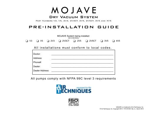
Dry Vacuum System<br />
Part Numbers V3, V5, 2V3, 2V3CT, 2V5, 2V5CT, 3V5 and 4V5<br />
<strong>PRE</strong>-<strong>INSTALLATION</strong> <strong>GUIDE</strong><br />
MOJAVE System being installed:<br />
(AS CHECKED)<br />
q V3 q V5 q 2V3 q 2V3CT q 2V5 q 2V5CT q 3V5 q 4V5<br />
All installations must conform to local codes.<br />
Doctor:<br />
Address:<br />
Phone#:<br />
Dealer:<br />
Dealer Address:<br />
__________________________________________________<br />
__________________________________________________<br />
__________________________________________________<br />
__________________________________________________<br />
__________________________________________________<br />
All pumps comply with NFPA 99C level 3 requirements<br />
MOJAVE is a trademark of <strong>Air</strong> <strong>Techniques</strong>, <strong>Inc</strong>.<br />
© <strong>Air</strong> <strong>Techniques</strong>, <strong>Inc</strong>. Copyright 2012 • P/N H5187, Rev. A, March 2012
MOJAVE SYSTEM CONFIGURATIONS<br />
System Components<br />
V3 V5 2V3 2V3CT 2V5 2V5CT 3V5 4V5<br />
V3 Pump Assembly 1 0 2 2 0 0 0 0<br />
From<br />
Treatment<br />
Room<br />
Gas/Liquids/<br />
Solids<br />
Gas<br />
Exhaust to<br />
Outside Vent<br />
V5 Pump Assembly 0 1 0 0 2 2 3 4<br />
MT10 Tank Assembly 1 1 1 0 1 0 0 0<br />
MT10<br />
Separator<br />
Tank<br />
CT20 Tank Assembly 0 0 0 1 0 1 1 1<br />
Liquids/Solids<br />
Master Controller Assembly 1 1 1 1 1 1 1 1<br />
Maximum Users 3 5 6 6 10 10 15 20<br />
Sewer<br />
Drain<br />
Check<br />
Valve<br />
Gate<br />
Valve<br />
V3 or V5<br />
Vacuum<br />
Pump<br />
Heat<br />
Exchanger<br />
Typical MOJAVE System Installation<br />
Recommended Number of Simultaneous HVE/SE Users<br />
V3 V5 2V3 or 2V3CT 2V5 or 2V5CT 3V5 4V5<br />
HVE SE HVE SE HVE SE HVE SE HVE SE HVE SE<br />
3 + 0 5 + 0 6 + 0 10 + 0 15 + 0 20 + 0<br />
2 + 2 4 + 2 5 + 2 9 + 2 14 + 2 18 + 4<br />
0 + 6 2 + 6 3 + 6 7 + 6 12 + 6 13 + 14<br />
0 + 10 1 + 10 5 + 10 9 + 12 10 + 20<br />
0 + 12 3 + 14 6 + 18 8 + 24<br />
Note: HVE = 2 SE’s<br />
1 HVE = 2 Nitrous Scavengers<br />
1 + 18 2 + 26 5 + 30<br />
0 + 20 0 + 30 0 + 40<br />
Master Controller<br />
Assembly<br />
MT10<br />
10 Gallon<br />
Physical Characteristics<br />
Tanks Typical V3 or V5 System Pump Configurations<br />
CT20<br />
Continuum<br />
MT10 Tank Stacked onto<br />
One V3 or V5 Pump<br />
One<br />
V3 or V5 Pump<br />
Two V3 or V5 Pumps<br />
Stacked<br />
Three<br />
V5 Pumps Stacked<br />
Width 11 in. (28 cm) 25 in. (64 cm) 25 in. (64 cm) 25 in. (64 cm) 25 in. (64 cm) 25 in. (64 cm) 25 in. (64 cm)<br />
Depth 3 in. (8 cm) 17 in. (43 cm) 20 in. (51 cm) 19 in. (48 cm) 19 in. (48 cm) 19 in. (48 cm) 19 in. (48 cm)<br />
Height 10 in. (24 cm) 23 in. (58 cm) 42 in. (107 cm) 50 in. (127 cm) 17 in. (43 cm) 34 in. (86 cm) 51 in. (130 cm)<br />
Weight 20 Lbs. (9 kg) 75 Lbs. (34 kg) 150 Lbs. (68 kg) 220 Lbs. (100 kg) 145 Lbs. (66 kg) 290 Lbs. (132 kg) 435 Lbs. (197 kg)
Assembly Dimensions<br />
11 in.<br />
(28 cm)<br />
13.5 in. (34 cm)<br />
11 in. (28 cm)<br />
3 in.<br />
(8 cm)<br />
10 in.<br />
(24 cm)<br />
Important:<br />
Never stack a CT20 Tank on top of any Pump.<br />
Never stack a Pump on top of any Tank.<br />
Recommend pumps only be stacked a maximum of two high.<br />
Leave a 4 inch service space around the Master Controller.<br />
All units shipped with all leveling feet set to lowest position.<br />
28.5 in.<br />
(72 cm)<br />
20 in.<br />
(51 cm)<br />
25 in.<br />
(64 cm)<br />
Master Controller Assembly Dimensions<br />
17 in.<br />
(43 cm)<br />
20 in.<br />
(51 cm)<br />
19 in.<br />
(48 cm)<br />
15.5 in.<br />
(39 cm)<br />
17 in.<br />
(43 cm)<br />
25 in.<br />
(64 cm)<br />
33 in.<br />
(84 cm)<br />
42 in.<br />
(107 cm)<br />
V3 and V5 Vacuum Pump Dimensions<br />
MT10 10 Gallon Tank Dimensions<br />
CT20 Continuum Tank Dimensions<br />
19 in.<br />
(48 cm)<br />
50 in.<br />
(127 cm)<br />
33 in.<br />
(84 cm)<br />
34 in.<br />
(86 cm)<br />
50 in.<br />
(127 cm)<br />
34 in.<br />
(86 cm)<br />
2V3 or 2V5 System Installation<br />
Recommended Stacked Pumps with Tank on Side<br />
V3 & V5 System Dimensions<br />
2V3CT or 2V5CT System Installation<br />
Recommended Stacked Pumps with CT20 Tank on Side
Sub FLOOR <strong>INSTALLATION</strong> -<br />
Recommended system installation layout should be used<br />
whenever possible.<br />
Ceiling<br />
Junction<br />
Box<br />
See Note 2.<br />
Treatment room PLUMBING <strong>INSTALLATION</strong>S<br />
Interior Wall<br />
1/2 - <strong>Inc</strong>h Diameter Riser Minimum Slope:<br />
1/4 inch per 10 Feet<br />
MAIN LINE See Notes 2, 3 & 4.<br />
Sub Floor<br />
Riser<br />
Connection<br />
See B.<br />
Main<br />
Line Turn<br />
Connection<br />
See A.<br />
Notes:<br />
1. 10-foot Maximum Height from Main<br />
Line to Tank.<br />
2. Consult Dental Unit Manufacturer's<br />
Guidelines for correct reduced size<br />
and height of termination of vacuum<br />
line inside junction box.<br />
3. Limit branches. Orient main line<br />
under junction box or cabinet.<br />
4. When piping line is above 3/4" I.D.<br />
or larger, use 45° Y's & elbows only.<br />
5. Recommend installing separate line<br />
connection for scavenger when using<br />
Nitrous scavengers in overhead<br />
piping installations.<br />
Main Line Riser for connection to<br />
tank input. See Note 1.<br />
Overhead <strong>INSTALLATION</strong> -<br />
Alternate system installation layout should be used only when<br />
unable to use the sub-floor plumbing layout.<br />
Minimum Slope:<br />
1/4 inch per 10 Feet<br />
Interior Wall<br />
1/2-<strong>Inc</strong>h Diameter Riser<br />
10-FT Maximum Height<br />
from Riser Trap to Main<br />
Line<br />
CONNECTOR DETAILS - ALL <strong>INSTALLATION</strong>S<br />
Ceiling<br />
Junction<br />
Box<br />
See Note 2.<br />
Riser Trap<br />
See D.<br />
Overhead Riser<br />
See C.<br />
MAIN LINE<br />
See Notes 2, 3<br />
4 & 5.<br />
q<br />
q<br />
q<br />
q<br />
Use only 45° elbows to make turns in main line.<br />
Make sure to use the proper pipe type for associated system.<br />
If piping is diverted to clear an obstruction, DO NOT MAKE A TRAP.<br />
See detail A, Main Line Turn Connections.<br />
DO NOT use standard 90° elbows.<br />
Important:<br />
All installation pipes and fittings provided by plumber.<br />
All installations must conform to local codes.<br />
A B C D<br />
45° Elbow<br />
Clearing &<br />
Obstruction<br />
Making<br />
Turns<br />
45° Elbow<br />
45°ELL<br />
Main<br />
Line<br />
To Dental Unit<br />
Junction Box<br />
1/2 <strong>Inc</strong>h Riser<br />
45°Y<br />
To<br />
Tank<br />
45°Elbow<br />
Main<br />
Line<br />
1" Min<br />
45°Elbow<br />
1/2 <strong>Inc</strong>h Riser<br />
1/2 <strong>Inc</strong>h<br />
Diameter<br />
45°Y<br />
To<br />
Tank<br />
1/2-<strong>Inc</strong>h<br />
Riser<br />
To Main<br />
Line<br />
1/2-<strong>Inc</strong>h<br />
To<br />
Dental Unit<br />
Junction<br />
Box<br />
Main Line Turn Connections<br />
Sub Floor Riser to Main Line Detail<br />
Overhead Riser to Main Line Detail<br />
(Prevents liquids from draining down the 1/2” riser.)<br />
Riser Trap Detail (45° Elbows)
Typical Equipment room floor plan layout<br />
4"<br />
D<br />
12"<br />
20"<br />
<strong>INSTALLATION</strong> NOTES:<br />
E<br />
48"<br />
4"<br />
Sewer Drain<br />
F<br />
C<br />
24"<br />
MT10 or CT20<br />
Tank<br />
B<br />
76"<br />
G<br />
62"<br />
4"<br />
H<br />
A<br />
12"<br />
J<br />
Single or<br />
Stacked Pumps<br />
(V3 or V5)<br />
107"<br />
1"<br />
4"<br />
24"<br />
Single or<br />
Stacked Pumps<br />
(V3 or V5)<br />
A<br />
K<br />
Pump/Tank<br />
Connection Manifold<br />
4"<br />
80"<br />
L<br />
23"<br />
1<br />
2<br />
Closed<br />
Vented<br />
Drain<br />
Top 3 <strong>Inc</strong>h<br />
45° Y<br />
Bottom<br />
3 <strong>Inc</strong>h<br />
45° Y<br />
OR<br />
2” Exhaust<br />
for Top Pump<br />
Connection<br />
2” Exhaust for<br />
Bottom Pump<br />
Connection<br />
Open<br />
Drain Pipe<br />
Bottom<br />
2 <strong>Inc</strong>h<br />
45° Y<br />
2” Exhaust for<br />
One Pump<br />
Connection<br />
2” Pipe for Addition of<br />
Drip Leg. See Note c.<br />
Notes: See Installation Note K below for required pipe material.<br />
a. A third 45° Y fitting may be added when preparing the<br />
site for a 3-pump system. All piping and fittings must<br />
be 4-inch instead of 3-inch on dual systems.<br />
b. Use a second dual 45° Y fitting configuration when<br />
preparing the site for a 4-pump system.<br />
c. Pipe required for the installation of a Drip Leg kit<br />
supplied with each pump. See exhaust ventilation<br />
requirements proved on the back cover.<br />
A. PUMP <strong>INSTALLATION</strong> SPACE - Area for stacked V3 or V5 pumps in typical side by side installations. Only stack up to 2 pumps in one area.<br />
B. TANK <strong>INSTALLATION</strong> SPACE - Area for MT10 or CT20 tank in typical side by side installations. Never install the CT20 tank on top of a pump.<br />
C. SEWER DRAIN - Provide a drain for the removal of waste liquids from the MOJAVE tank. Use an open drain pipe (1 ½” inch P-Trap with 1 inch air gap<br />
or floor sink) or a closed vented drain. See detail 1.<br />
D. TANK WASHOUT - Provide a water source terminated with a ½” inch FNPT shut-off valve providing water pressure between 20 and 100 psi for daily<br />
tank washout. Valve location must be no more than 10 feet from the tank installation to allow connection of supplied 10-foot 3/8-inch Poly tubing to<br />
the tank washout port. Provisions for backflow prevention may be required. Check local code requirements.<br />
E. MASTER CONTROLLER UNIT - Locate near pump and also allow a space around the Master Controller of at least 4 inches for the connection of wiring<br />
and the line cord during installation and servicing.<br />
F. MASTER CONTROLLER ELECTRIC OUTLET - Master Controller requires a dedicated standalone 120V, 5 AMP grounded receptacle.<br />
G. PUMP ELECTRIC SERVICE - Each Mojave pump is wired directly with a dedicated 220V, 20 AMP, single phase 60 Hz circuit. If Main Circuit panel is<br />
not located in equipment room, a disconnect box with approved ground is needed for each pump. Disconnect boxes should be mounted no more<br />
than 3 feet of each other and 3 feet of installation center line.<br />
H. Sub FLOOR <strong>INSTALLATION</strong> VACUUM LINE - See Plumbing Requirements for connection to tank input via supplied hose.<br />
J. Overhead <strong>INSTALLATION</strong> VACUUM LINE - See Plumbing Requirements for connection to tank input via supplied hose.<br />
K. HEAT EXHAUST - See Plumbing Requirements for the exhaust vent line required for specific Mojave configurations. Use metal pipe on systems whenever<br />
the Heat Exchanger is removed. Schedule 40 pipe can normally be used on typical Mojave configuration installations with a Heat Exchanger. When<br />
installing two pumps, a reducing Y adapter (shown by detail 2 above) is needed to connect both vent tubes to a common 3-inch exhaust vent line.<br />
L. PUMP/TANK MANIFOLD - User fabricated to connect 3 or 4 pumps to a tank. Used with 3V5 and 4V5 systems. See Pump/Tank Connection Manifold.
SITE REQUIREMENTS<br />
Electrical V3 V5 2V3 & 2V3CT 2V5 & 2V5CT 3V5 4V5 Master Controller<br />
Voltage Rating All pumps 220 Volts Single Phase AC, 60 Hz 120<br />
Voltage Minimum/Maximum 205/240 Volts AC All pumps 108/132 Volts AC<br />
Wire Size AWG Minimum Gauge<br />
#12 AWG<br />
(Qty 1)<br />
#12 AWG<br />
(Qty 1)<br />
#12 AWG<br />
(Qty 2)<br />
#12 AWG<br />
(Qty 2)<br />
#12 AWG<br />
(Qty 3)<br />
#12 AWG<br />
(Qty 4)<br />
Minimum Circuit Breaker Rating 20A 20A 20A (Qty 2) 20A (Qty 2) 20A (Qty 3) 20A (Qty 4) 15A<br />
#14 AWG<br />
<strong>Inc</strong>oming Power<br />
Hard wire Connection (Each pump is supplied with a 4 x 4 handy box and a 4 foot whip)<br />
NEMA 5-15R<br />
(Supplied 6 ft. line cord)<br />
Plumbing V3 V5 2V3 OR 2V3CT 2V5 OR 2V5CT 3V5 4V5<br />
Exhaust Vent Pipe Using<br />
Heat Exchanger<br />
2” PVC Sch. 40 2” PVC Sch. 40<br />
One 3” or two 2” PVC<br />
Sch. 40<br />
One 3” or two 2” PVC<br />
Sch. 40<br />
One 4” or three 2”<br />
PVC Sch. 40<br />
Two 3” or four 2” PVC<br />
Sch. 40<br />
Exhaust Vent Pipe Not<br />
Using Heat Exchanger<br />
(See note 1)<br />
2” Metal Pipe 2” Metal Pipe<br />
One 3” or two 2” Metal<br />
Pipe<br />
One 3” or two 2” Metal<br />
Pipe<br />
One 4” or three 2”<br />
Metal Pipe<br />
Two 3” or four 2”<br />
Metal Pipe<br />
Minimum Suction Line Pipe 1” PVC Sch. 40 1 ½” PVC Sch. 40 1 ½” PVC Sch. 40 2” PVC Sch. 40 3” PVC Sch. 40 3” PVC Sch. 40<br />
Maximum Suction Line Pipe<br />
(See note 2)<br />
1 ½” PVC Sch. 40 2” PVC Sch. 40 2” PVC Sch. 40 2 ½” PVC Sch. 40 4” PVC Sch. 40 4” PVC Sch. 40<br />
Riser Pipe ½” PVC Sch. 40 ½” PVC Sch. 40 ½” PVC Sch. 40 ½” PVC Sch. 40 ½” PVC Sch. 40 ½” PVC Sch. 40<br />
Vacuum Line Termination 1 ½” FNPT 2” FNPT 2” FNPT 2” FNPT 2” FNPT 2” FNPT<br />
Branch Line Pipe<br />
Size requirement of Branch piping differs by the number of operatories being serviced.<br />
Up to two operatories use 1” PVC Schedule 40<br />
Three to six operatories use 1 ½” PVC Schedule 40<br />
More that six operatories use 2” PVC Schedule 40<br />
Drain Line Pipe 1 ½” PVC Sch. 40<br />
Wash-Out Water Line<br />
½” FNPT Shut-off Valve<br />
NOTES<br />
1. Recommended for all new installations.<br />
2. Use maximum internal diameter for the main line when preparing any new installation.
PUMP/TANK CONNECTION MANIFOLD<br />
Pump/Tank Connection Manifold Using Accessory Kit<br />
3” PVC or Copper<br />
Tubing & Elbow<br />
(Supplied by Plumber)<br />
Sanitary Tee with 1-1/2” FNPT End<br />
Fitting. 3 or 4 depending on system<br />
configuration. (Supplied by Plumber)<br />
<strong>Air</strong> Flow<br />
3” PVC or Copper<br />
Clean-out Plug Used with P/N MIK4<br />
(Supplied by Plumber)<br />
2” PVC or Copper<br />
Tubing for Tank Hose<br />
(Supplied by Plumber)<br />
1.5 ft<br />
1 ft<br />
3 or 4 Supplied Check<br />
Valve Assemblies -<br />
See Kit<br />
P/N MIK4<br />
Check Valve Installed<br />
Flat Side Facing Up<br />
Horizontal to Floor<br />
Barbed Connector<br />
to Pump<br />
Flat Side Installed<br />
Facing Up<br />
1-1/2” FNPT to<br />
Sanitary Tee<br />
Note: Hang using at least<br />
3 pipe supports supplied by<br />
Plumber.<br />
Hoses From<br />
Manifold To Pumps<br />
Hose Between Manifold<br />
and CT20 Tank Secured<br />
by Flexible Couplers<br />
Check Valve<br />
Assembly Side View<br />
Hose Between<br />
Manifold and<br />
CT20 Tank<br />
Secured by<br />
Flexible Couplers<br />
Hoses From<br />
Manifold To Pumps<br />
V3 & V5<br />
PUMP HOSE<br />
CONNECTION<br />
DETAIL<br />
Hose from Manifold Connected to Pump<br />
via <strong>Air</strong> Input Filter Barbed Adapter<br />
CLASSIFIED<br />
MEDICAL ELECTRICAL EQUIPMENT<br />
WITH RESPECT TO ELECTRICAL SHOCK, FIRE, MECHANICAL<br />
AND OTHER SPECIFIED HAZARDS ONLY<br />
IN ACCORDANCE WITH UL-60601-1, CAN/CSA C22.2 NO.601.1 66CA
EXHAUST VENTILATION REQUIREMENTS<br />
HEAT EXHAUST CONNECTION NOTES<br />
Heat<br />
Exchanger<br />
1. VENT LINE - The exhaust vent line required for MOJAVE systems using<br />
the Heat Exchanger and systems with the Heat Exchanger removed<br />
have different requirements.<br />
Use metal pipe on systems without a Heat Exchanger while PVC<br />
Schedule 40 pipe can be used on systems with a Heat Exchanger.<br />
Do not make a trap in the exhaust vent piping.<br />
Also see Exhaust Vent Protection and Ventilation Requirements below.<br />
2. V3 & V5 PUMP EXHAUST VENT CONNECTION - Connection between<br />
the pump and exhaust vent piping is typically made via the supplied 2-inch<br />
Black Flex tubing.<br />
Typical Flex<br />
Tubing<br />
See Note 2.<br />
4”<br />
Exhaust Vent<br />
See Note 1.<br />
35”<br />
V3 or V5 Pump Top View<br />
2” Flexible Coupler<br />
2” PVC Reducing Bushing<br />
Vent Pipe<br />
17-<strong>Inc</strong>h Long<br />
Flex Tubing<br />
3. DRIP LEG - The supplied drip leg must be installed at the lower<br />
end of the vent pipe to collect condensation produced during pump<br />
operation. The bottom of drip leg should be located a minimum of 4<br />
inches from floor. Attach the drain tube to the drip leg quick-connect fitting<br />
to allow drainage into floor drain/sink.<br />
4”<br />
Drip Leg<br />
See Detail<br />
& Note 3.<br />
18”<br />
V3 & V5 Pump Heat Exchanger Connection<br />
3/4” MNPT X 1/4” FNPT PVC Bushing<br />
1/4” MNPT X 1/4” Push Elbow<br />
Drip Leg Detail View<br />
Exhaust Vent Protection.<br />
If the exhaust piping is venting to the outside of the building, precautions must be taken to protect<br />
the equipment room from weather elements and animal intrusion. This can be accomplished by<br />
using one of the three methods shown on the right.<br />
Roof-Mounted Outside Vent Protection<br />
Screen<br />
Shroud &<br />
Screen<br />
Shroud &<br />
Screen<br />
Wall-Mounted Outside<br />
Vent Protection<br />
Exhaust Vent Requirements.<br />
The MOJAVE equipment must be used in a controlled-temperature environment. Maintain<br />
equipment room temperature between 40 and 105 degrees Fahrenheit. An exhaust fan is<br />
necessary if room temperature is not maintained by other methods.<br />
Adequate forced ventilation must be provided across the unit by placing an appropriate<br />
exhaust fan opposite an equivalent air intake vent . The fan should be placed higher than the<br />
associated intake vent. Recommended minimum exhaust fan requirements for each MOJAVE<br />
unit are listed to the right.<br />
MOJAVE<br />
Unit<br />
Watts<br />
(Idle)<br />
Watts<br />
(Max)<br />
BTU<br />
(Idle)<br />
BTU<br />
(Max)<br />
V3 1,800 2,500 6,140 8,530<br />
V5 1,800 3,500 6,140 12,942<br />
2V3 & 2V3CT 3,600 5,000 12,280 17,060<br />
2V5 & 2V5CT 3,600 7,000 12,280 25,884<br />
3V5 5,400 7,500 18,420 38,826<br />
4V5 7,200 14,000 24,560 51,768