DT Series Technical Manual - MECS
DT Series Technical Manual - MECS
DT Series Technical Manual - MECS
Create successful ePaper yourself
Turn your PDF publications into a flip-book with our unique Google optimized e-Paper software.
INDUSTRIAL<br />
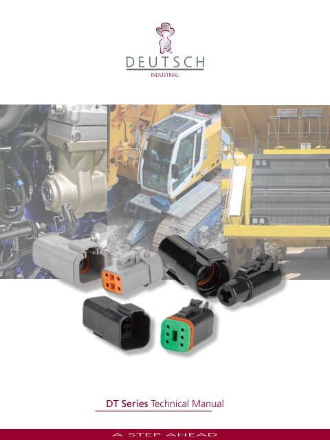
<strong>DT</strong> <strong>Series</strong> <strong>Technical</strong> <strong>Manual</strong><br />
A STEP AHEAD<br />
<strong>DT</strong> <strong>Series</strong> <strong>Manual</strong> #50907.indd 1<br />
7/31/2008 5:14:33 PM
<strong>DT</strong> <strong>Series</strong> <strong>Technical</strong> <strong>Manual</strong><br />
Table of Contents<br />
Introduction<br />
2, 3<br />
Contact Retention System<br />
10<br />
Features & Benefits<br />
3<br />
Assembly Contact Insertion / Removal<br />
11<br />
Product Line Overview<br />
4<br />
Accessories<br />
12<br />
Material Specifications<br />
5<br />
Shrink Boot Adaptor<br />
12<br />
General Specifications<br />
5<br />
Removal Tools / Sealing Plugs<br />
12<br />
Ordering Information<br />
6<br />
<strong>DT</strong> Mounting Clips<br />
13<br />
Insert Arrangements<br />
7, 8<br />
Back Shells<br />
14, 15<br />
Contacts & Application Data<br />
9<br />
Environmentally-Sealed Transportation Connectors<br />
Deutsch <strong>DT</strong>M <strong>Series</strong><br />
Deutsch <strong>DT</strong>M <strong>Series</strong> of transportation connectors feature a<br />
miniature contact with an enhanced design based on the<br />
world class, field-proven Deutsch <strong>DT</strong> <strong>Series</strong>.<br />
The <strong>DT</strong>M is the connector to be used in harsh environmental<br />
application where reliable signal circuits are critical to<br />
operating performance. Typical applications include on or<br />
around the engine, the transmission and under the hood.<br />
Deutsch <strong>DT</strong> <strong>Series</strong><br />
An environmentally-sealed connector designed specifically for<br />
cable to cable applications on the engine or transmission, under<br />
the hood, on the chassis or in the cab. On signal level circuits in<br />
harsh environmental conditions, where even a small degradation<br />
in connection may be critical, the Deutsch <strong>DT</strong> <strong>Series</strong> general<br />
purpose connectors will provide the reliability and performance<br />
at the lowest cost.<br />
2<br />
A STEP AHEAD<br />
<strong>DT</strong> <strong>Series</strong> <strong>Manual</strong> #50907.indd 2<br />
7/31/2008 5:14:33 PM
<strong>DT</strong> <strong>Series</strong> <strong>Technical</strong> <strong>Manual</strong><br />
Deutsch <strong>DT</strong>P <strong>Series</strong><br />
Deutsch’s <strong>DT</strong>P <strong>Series</strong> connectors are the answer to all of<br />
your most demanding power application requirements.<br />
<strong>DT</strong>P <strong>Series</strong> connectors offer the proven reliability and<br />
quality of Deutsch’s <strong>DT</strong> <strong>Series</strong>, combined with the added<br />
flexibilty of using power contacts.<br />
Deutsch <strong>DT</strong>HD <strong>Series</strong><br />
Deutsch developed the <strong>DT</strong>HD <strong>Series</strong> for those applications<br />
requiring a complete, environmentally sealed, single power circuit<br />
termination. The plug features an integral coupling latch that<br />
provides tactile and audible feedback during coupling. The rugged<br />
thermoplastic receptacle is designed as an inline for cable to cable<br />
applications and is supplied with an integral Vee-Groove to accept<br />
mounting, clips, brackets and flanges.<br />
Deutsch <strong>DT</strong> Bussed <strong>Series</strong><br />
Utilizing the Deutsch <strong>DT</strong> receptacle shell, Deutsch has<br />
combined the rugged characteristics of the <strong>DT</strong> product<br />
line with a bussing device allowing the elimination of<br />
various harness splices. By using internal stamped bussed<br />
contacts this product can be configured in whatever<br />
arrangement meets your individual needs in the <strong>DT</strong> shell<br />
size that matches your requirements. Complete bussing<br />
flexibility in a compact, economical package.<br />
Features<br />
Integral Connector Latch<br />
Rugged Thermoplastic Housing<br />
-55 o C to +125 o C Operating Temperature<br />
Available Configurations:<br />
<strong>DT</strong>M/<strong>DT</strong> 2, 3, 4, 6, 8 & 12 - Size 20/16<br />
<strong>DT</strong>P 2 & 4 - Size 12<br />
<strong>DT</strong>HD 1 - Size 4, 8 & 12<br />
Silicone Seals:<br />
<strong>DT</strong>M: Accepts AWG 22 - 16 wire<br />
<strong>DT</strong>: Accepts AWG 20 - 14 wire<br />
<strong>DT</strong>P: Accepts AWG 14 - 10 wire<br />
<strong>DT</strong>HD: Accepts AWG 14 - 6 wire<br />
Crimp Contacts with Option of Gold or Nickel<br />
Finish, Solid or Stamped Construction<br />
Current rating all contacts @ 125 0 C no derating<br />
<strong>DT</strong>M - 7.5 Amps<br />
<strong>DT</strong> - 13 Amps<br />
<strong>DT</strong>P - 25 Amps<br />
<strong>DT</strong>HD - 25 to 100 Amps<br />
Fail-Safe Secondary Locks All (Except <strong>DT</strong>HD)<br />
Hand Insertable/Removable Contacts<br />
Budget Minded<br />
Benefits<br />
Tactile and Audible Assembly Feedback<br />
Field Proven Long Service Life<br />
Engine Compartment Rated<br />
Meets Most Harness Design Requirements<br />
Superior Environmental Seal<br />
Seals on .053” to .120 dia.(1.35mm to 3.05mm)<br />
Seals on .053” to .145 dia.(1.35mm to 3.68 mm)<br />
Seals on .097” to .170 dia.(2.46mm to 4.32mm)<br />
Seals on .134 to .292 dia. (3.40mm to 7.42mm)<br />
Low Costs, High Reliability Terminals for Data &<br />
Signal Transmission<br />
Meets Most Signal Requirements<br />
Positive Contact Retention<br />
No Special Tools Required (Except <strong>DT</strong>HD)<br />
Low Installation Costs<br />
3<br />
A STEP AHEAD<br />
<strong>DT</strong> <strong>Series</strong> <strong>Manual</strong> #50907.indd 3<br />
7/31/2008 5:14:34 PM
<strong>DT</strong> <strong>Series</strong> <strong>Technical</strong> <strong>Manual</strong><br />
Product Line Overview<br />
Deutsch <strong>DT</strong>M <strong>Series</strong><br />
Deutsch <strong>DT</strong>M <strong>Series</strong> of transportation connectors feature a<br />
miniature contact with an enhanced design based on the world<br />
class, field-proven Deutsch “<strong>DT</strong> <strong>Series</strong>”.<br />
The <strong>DT</strong>M is the connector to be used in harsh environmental<br />
applications where reliable signal circuits are critical to operating<br />
performance. Typical applications include on or around the<br />
engine, the transmission and under the hood. In fact, everywhere<br />
data signals or critical electronic circuits go, the field proven<br />
Deutsch design of the <strong>DT</strong>M will provide reliable peak connector<br />
performance.<br />
The low cost, size 20 contacts terminate AWG 16 to 22 gauge<br />
wire (0.5mm 2 to 1.5mm 2 ). Closed entry socket (female) contacts<br />
featuring spring action fingers are protected by a stainless steel<br />
hood. This allows for positive axial alignment while mating and<br />
prevents probe damage during testing.<br />
Thermoplastic housings offer a wide operating temperature<br />
range (-55 0 C to +125 0 C). Silicone rear wire and internal<br />
peripheral interface seals allow the <strong>DT</strong>M to withstand moisture<br />
and fluids.<br />
Deutsch <strong>DT</strong>P <strong>Series</strong><br />
Building on both the <strong>DT</strong> and <strong>DT</strong>M design strengths, the <strong>DT</strong>P<br />
connector line was developed to fill the need for higher amperage,<br />
multi-pin, inexpensive connectors. The series meets the same<br />
specifications as the <strong>DT</strong>M and <strong>DT</strong> but offers the designer the ability<br />
to use multiple 12 gauge contacts, each with a 25 amp continuous<br />
capacity, within a single shell.<br />
Based on the <strong>DT</strong>M overall design, it offers the protected interfacial<br />
seal located within the receptacle shell. Standard multi-seal grommet<br />
is used in both the plug and receptacle. Currently available in two and<br />
four pin configurations.<br />
Deutsch <strong>DT</strong> Bussed <strong>Series</strong><br />
These standard “<strong>DT</strong>” receptacle shells feature internal pin type<br />
contact buss bar arrangements that allow common connections<br />
from 3 to 12 size 16 contacts. Buss bars are available in standard<br />
nickel or gold to match common Deutsch Industrial contacts.<br />
Other features include the use of standard “<strong>DT</strong>” plugs to mate<br />
with these environmental receptacles. Plugs with any Deutsch<br />
modification are intermatable.<br />
Deutsch <strong>DT</strong> <strong>Series</strong><br />
Deutsch <strong>DT</strong> <strong>Series</strong> of environmentally-sealed, connectors are<br />
designed specifically for cable to cable applications on the engine<br />
or transmission, under the hood, on the chassis or in the cab.<br />
Where signal level circuits in harsh environmental conditions,<br />
where even a small degradation in connection may be critical,<br />
the Deutsch <strong>DT</strong> <strong>Series</strong> general purpose connectors will provide<br />
the reliability and performance at the lowest cost.<br />
Thermoplastic (-55 0 C to + 125 0 C rated) housings and silicone<br />
seals are used to allow the connector to withstand conditions<br />
of extreme temperature and moisture. The connector may be<br />
employed with either solid-copper crimp type contacts for critical<br />
circuits or budget-minded stamped and formed contacts. In<br />
either selection, the spring action is designed in the socket and<br />
shrouded by a stainless steel hood that provides closed entry for<br />
positive axial alignment during mating, and eliminates probe<br />
damage from occurring. Contact insertion and withdrawal require<br />
no special tools and are retained in locked position by dielectic<br />
fingers, molded as an integral part of the housing. Secondary<br />
locks are assembled at the mating interfaces. If by chance the<br />
secondary locks are not properly seated during assembly, they<br />
will be pressed into locked position during the mating of the<br />
connector.<br />
Deutsch <strong>DT</strong>HD <strong>Series</strong><br />
Deutsch developed the <strong>DT</strong>HD <strong>Series</strong> for those applications requiring a<br />
complete, environmentally sealed, single power circuit termination.<br />
<strong>DT</strong>HD plugs and receptacles can be permanently assembled with<br />
thermoplastic end caps that prevent removal of the silicone wire<br />
seal grommets. Designed for diesel engine, electronic fuel injectors,<br />
automatic transmissions, ABS brakes and other applications that<br />
involve fuel and oil exposure. These end caps provide the additional<br />
reliability required for critical wiring circuits.<br />
4<br />
A STEP AHEAD<br />
<strong>DT</strong> <strong>Series</strong> <strong>Manual</strong> #50907.indd 4<br />
7/31/2008 5:14:35 PM
<strong>DT</strong> <strong>Series</strong> <strong>Technical</strong> <strong>Manual</strong><br />
MATERIAL SPECIFICATIONS<br />
Plug/Receptacle<br />
Shell: Thermoplastic<br />
Wedge: Thermoplastic<br />
Grommet: Silicone Rubber<br />
Contacts<br />
Pin:<br />
Socket:<br />
Finish:<br />
Sealing Plugs<br />
Thermoplastic: (All sizes)<br />
Copper Alloy<br />
Copper Alloy<br />
Nickel (optional - gold) Plated<br />
GENERAL SPECIFICATIONS<br />
Dielectric Withstanding Voltage<br />
Current leakage less than 2 milliamps at 1500 VAC<br />
Insulation Resistance:<br />
1000 megohms minimum at 25 0 C.<br />
Current Rating (Contact current rating @ 125 0 C (continuous)<br />
Size 20: 7.5 amps<br />
Size 16: 13 amps<br />
Size 12: 25 amps<br />
Size 8: 60 amps<br />
Size 4: 100 amps<br />
Submersion:<br />
Properly wired and mated connection will withstand immersion under<br />
three feet of water without loss of electronic qualities or leakage.<br />
Fluid Resistance:<br />
Connectors show no damage when exposed to most fluids used in<br />
industrial applications.<br />
Vibration:<br />
No unlocking or unmating and exhibits no mechanical or physical<br />
damage after sinusoidal vibration levels of 20 G’s at 10 to 2000<br />
Hz in each of the three mutually perpendicular planes. No electrical<br />
discontinuities longer than 1 microsecond.<br />
Thermal Cycle:<br />
No cracking, chipping or leaking after 20 test cycles from<br />
-55 0 C to +125 0 C.<br />
Durability:<br />
No electrical or mechanical defects after 100 cycles of<br />
engagement and disengagement.<br />
CONTACT<br />
SIZE<br />
20<br />
CONTACT RESISTANCE<br />
WIRE GAUGE<br />
AWG(mm 2 )<br />
20 (.50)<br />
18 (.80)<br />
16 (1.0)<br />
16 20 (.50)<br />
18 (.80)<br />
16 (1.0)<br />
Test Current<br />
(Amps)<br />
Resistance (mV)<br />
Solids<br />
Resistance (mV)<br />
Stamped & Formed<br />
7.5 60 100<br />
7.5 60 100<br />
7.5 60 100<br />
7.5 60 100<br />
10 60 100<br />
13 60 100<br />
14 (2.0) 13 60 100<br />
12 14 (2.0) 18 60 100<br />
12 (3.0) 25 60 100<br />
8<br />
4<br />
8 (8.60)<br />
10 (5.60)<br />
CONTACT SIZE<br />
#20<br />
#16<br />
#12<br />
#8<br />
#4<br />
60<br />
60<br />
60 N/A<br />
60 N/A<br />
6 (13.0) 100 60 N/A<br />
WIRE SEALING RANGE<br />
RECOMMENDED WIRE INSULATION O.D.<br />
N-SEAL<br />
.053-.120<br />
(1.35-3.05)<br />
.088-.145<br />
(2.24-3.68)<br />
.134-.170<br />
(3.40-4.32)<br />
.190-.240<br />
(4.83-6.10)<br />
.280-.292<br />
(7.11-7.42)<br />
E-SEAL<br />
N/A<br />
.053-.120<br />
(1.35-3.05)<br />
.097-.158<br />
(2.46-4.01)<br />
N/A<br />
N/A<br />
Temperature:<br />
Operative at temperatures from -55 0 C to +125 0 C. Continuous at rated<br />
current.<br />
Contact Retention:<br />
Contacts withstand a minimum load of:<br />
20 lbs (89N) for size 20<br />
25 lbs (111N) for size 16<br />
30 lbs (133N) for size 12<br />
35 lbs (156N) for size 8<br />
35 lbs (156N) for size 4<br />
5<br />
A STEP AHEAD<br />
<strong>DT</strong> <strong>Series</strong> <strong>Manual</strong> #50907.indd 5<br />
7/31/2008 5:14:35 PM
<strong>DT</strong> <strong>Series</strong> <strong>Technical</strong> <strong>Manual</strong><br />
PART NUMBERING SYSTEM (<strong>DT</strong>M)<br />
<strong>DT</strong>M 06 - 2 S * - ****<br />
<strong>Series</strong> Prefix<br />
04 = Receptacle<br />
06 = Plug<br />
Number of Contacts<br />
Special Modifications<br />
Polarizing Position (If Applicable)<br />
08 + 12 Only<br />
Contact Type<br />
P = Pin Receptacle Only<br />
S = Socket Plug Only<br />
PART NUMBERING SYSTEM (<strong>DT</strong> & <strong>DT</strong> Bussed)<br />
<strong>DT</strong> 06 - 2 S * - ****<br />
<strong>Series</strong> Prefix<br />
04 = Receptacle<br />
06 = Plug<br />
Number of Contacts<br />
Special Modifications<br />
Polarizing Position<br />
(If Applicable)<br />
Contact Type<br />
P = Pin Receptacle Only<br />
S = Socket Plug Only<br />
PART NUMBERING SYSTEM (<strong>DT</strong>P)<br />
<strong>DT</strong>P 06 - 2 S * - ****<br />
<strong>Series</strong> Prefix<br />
04 = Receptacle<br />
06 = Plug<br />
Number of Contacts<br />
Special Modifications<br />
Polarizing Position<br />
(If Applicable)<br />
Contact Type<br />
P = Pin Receptacle Only<br />
S = Socket Plug Only<br />
PART NUMBERING SYSTEM (<strong>DT</strong>HD)<br />
<strong>DT</strong>HD 06 - 1 - 4 S - ****<br />
<strong>Series</strong> Prefix<br />
04 = Receptacle<br />
06 = Plug<br />
Single Terminal<br />
Contact Size<br />
4 = Size 4<br />
8 = Size 8<br />
12 = Size 12<br />
Special Modifications<br />
Contact Style<br />
P = Pin Receptacle Only<br />
S = Socket Plug Only<br />
6<br />
A STEP AHEAD<br />
<strong>DT</strong> <strong>Series</strong> <strong>Manual</strong> #50907.indd 6<br />
7/31/2008 5:14:35 PM
<strong>DT</strong> <strong>Series</strong> <strong>Technical</strong> <strong>Manual</strong><br />
<strong>DT</strong>M <strong>Series</strong> Size 20 Contacts<br />
2<br />
2 size 20<br />
3<br />
3 size 20<br />
4<br />
4 size 20<br />
6<br />
6 size 20<br />
8<br />
8 size 20<br />
12<br />
12 size 20<br />
<strong>DT</strong> & <strong>DT</strong> BUSSED <strong>Series</strong> Size 16 Contacts<br />
2<br />
2 size 16<br />
3<br />
3 size 16<br />
4<br />
4 size 16<br />
6<br />
6 size 16<br />
8<br />
8 size 16<br />
12<br />
12 size 16<br />
<strong>DT</strong>P <strong>Series</strong> Size 12 Contacts<br />
2<br />
2 size 12<br />
4<br />
4 size 12<br />
<strong>DT</strong>HD <strong>Series</strong> Size 4, 8 & 12<br />
1<br />
1 size 4<br />
1<br />
1 size 8<br />
1<br />
1 size12<br />
7<br />
A STEP AHEAD<br />
<strong>DT</strong> <strong>Series</strong> <strong>Manual</strong> #50907.indd 7<br />
7/31/2008 5:14:35 PM
<strong>DT</strong> <strong>Series</strong> <strong>Technical</strong> <strong>Manual</strong><br />
<strong>DT</strong> <strong>Series</strong> BUSSED Arrangements<br />
Standard <strong>DT</strong> Receptacles Bussed to Customer Specifications<br />
1 4<br />
2 3<br />
DEUTSCH<br />
1 6<br />
2<br />
5<br />
DEUTSCH<br />
4<br />
3<br />
6<br />
1<br />
2<br />
5<br />
DEUTSCH<br />
4<br />
3<br />
4 PIN 6 PIN<br />
6 PIN<br />
8<br />
7<br />
6 5<br />
8<br />
7<br />
6 5<br />
8<br />
7<br />
6 5<br />
1 2<br />
DEUTSCH<br />
8 PIN<br />
4 3<br />
1 2<br />
DEUTSCH<br />
8 PIN<br />
4 3<br />
2 1<br />
DEUTSCH<br />
8 PIN<br />
4 3<br />
12<br />
11<br />
10 9<br />
8<br />
7<br />
12 11 10 9 8 7<br />
4<br />
2 1 5<br />
3<br />
DEUTSCH<br />
6<br />
1<br />
2<br />
3<br />
4<br />
DEUTSCH<br />
6 5<br />
12 PIN<br />
12 PIN<br />
12 11 10 9 8 7<br />
1<br />
2<br />
3<br />
DEUTSCH<br />
4<br />
6 5<br />
12 PIN<br />
Arrangements shown are currently available. For additional arrangements contact factory.<br />
ALL PART NUMBERS ARE<br />
FOR “BLACK”<br />
MAX CURRENT RATINGS<br />
NICKEL BUSS P/N<br />
GOLD BUSS P/N<br />
MATING PLUG P/N<br />
4 PIN = 26 AMPS<br />
<strong>DT</strong>04-4P-EP13<br />
<strong>DT</strong>04-4P-EP12<br />
<strong>DT</strong>06-4S-****<br />
6 PIN = 39 AMPS<br />
<strong>DT</strong>04-6P-EP13<br />
<strong>DT</strong>04-6P-EP12<br />
<strong>DT</strong>06-6S-****<br />
3 PIN = 13 AMPS<br />
<strong>DT</strong>04-6P-EP14<br />
<strong>DT</strong>04-6P-EP15<br />
<strong>DT</strong>06-6S-****<br />
8 PIN = 52 AMPS<br />
<strong>DT</strong>-8PB-P021<br />
<strong>DT</strong>04-8PB-P016<br />
<strong>DT</strong>06-08SB-****<br />
5 PIN = 26 AMPS<br />
<strong>DT</strong>04-8PB-PO28<br />
<strong>DT</strong>04-8PB-PO29<br />
<strong>DT</strong>06-08SB-****<br />
4 PIN = 26 AMPS<br />
<strong>DT</strong>04-8PB-P026<br />
<strong>DT</strong>04-8PB-P027<br />
<strong>DT</strong>06-08SB-****<br />
3 PIN = 13 AMPS<br />
<strong>DT</strong>04-3P-***<br />
<strong>DT</strong>04-3P-***<br />
<strong>DT</strong>06-3S-****<br />
12 PIN = 76 AMPS<br />
<strong>DT</strong>04-12PB-P021<br />
<strong>DT</strong>04-12PB-P016<br />
<strong>DT</strong>06-12SB-****<br />
6 PIN = 39 AMPS<br />
<strong>DT</strong>04-12PB-P026<br />
<strong>DT</strong>04-12PB-P027<br />
<strong>DT</strong>06-12SB-****<br />
3 PIN = 13 AMPS<br />
<strong>DT</strong>04-12PB-P030<br />
<strong>DT</strong>04-12PB-P031<br />
<strong>DT</strong>06-12SB-****<br />
PLEASE CONSULT FACTORY FOR AVAILABILITY AND ALTERNATE KEYING<br />
8<br />
A STEP AHEAD<br />
<strong>DT</strong> <strong>Series</strong> <strong>Manual</strong> #50907.indd 8<br />
7/31/2008 5:14:36 PM
<strong>DT</strong> <strong>Series</strong> <strong>Technical</strong> <strong>Manual</strong><br />
CONTACTS AND APPLICATION DATA<br />
Solid Contacts<br />
SIZE<br />
20<br />
16<br />
16<br />
12<br />
8<br />
4<br />
Socket<br />
PIN<br />
SOLID CONTACT<br />
PART NUMBERS<br />
SOCKET<br />
0460-202-20** 0462-201-20**<br />
0460-202-16** 0462-201-16**<br />
0460-215-16** 0462-209-16**<br />
0460-204-12** 0462-203-12**<br />
0460-204-08** 0462-203-08**<br />
0460-204-04** 0462-203-04**<br />
Solid Contacts<br />
INSPECTION HOLE<br />
WIRE SIZE<br />
AWG (mm 2 )<br />
20<br />
(0.50)<br />
16-20<br />
(1.0 - 0.50)<br />
14<br />
(2.0)<br />
12-14<br />
(3.0 - 2.0)<br />
8-10<br />
(8.0 - 5.0)<br />
6<br />
(13.0)<br />
RECOMMENDED<br />
STRIP LENGTH<br />
INCHES (mm)<br />
.156-.218<br />
(3.96 - 5.54)<br />
.250 - .312<br />
(6.35 - 7.92)<br />
.250 - .312<br />
(6.35 - 7.92)<br />
.222 - .284<br />
(5.64 - 7.21)<br />
.430 - .492<br />
(10.92 - 12.50)<br />
.430-.492<br />
(10.92-12.50)<br />
* See Envelope Print 0425-205-0000. Consult factory for alternate finishes.<br />
MIN CONTACT<br />
RETENTION<br />
LBS (N)<br />
Stamped and Formed Contacts<br />
Pin<br />
20<br />
(89)<br />
25<br />
(111)<br />
25<br />
(111)<br />
30<br />
(134)<br />
35<br />
(156)<br />
35<br />
(156)<br />
REF CRIMP<br />
TENSILE<br />
LBS (N)<br />
MAX RATED<br />
AMPS AT 125 0 C<br />
CONTINUOUS<br />
20<br />
7.5<br />
(89)<br />
35-20<br />
13<br />
(156-89)<br />
70<br />
(311)<br />
13<br />
75-70<br />
(334 - 311)<br />
25<br />
125-90<br />
(556-400) 60<br />
300<br />
(1334)<br />
Socket<br />
100<br />
Pin<br />
INSPECTION HOLE<br />
Stamped & Formed Contacts<br />
SIZE<br />
20<br />
20<br />
20<br />
16<br />
16<br />
16<br />
16<br />
16<br />
16<br />
16<br />
16<br />
12<br />
12<br />
STAMPED & FORMED CONTACT<br />
PART NUMBERS<br />
PIN<br />
SOCKET<br />
1060-20-01** 1062-20-01**<br />
1060-20-02** 1062-20-02**<br />
N/A 1062-20-03**<br />
1060-14-01** 1062-14-01**<br />
1060-14-10** 1062-14-10**<br />
1060-16-01** 1062-16-01**<br />
1060-16-06** 1062-16-06**<br />
1060-16-07** 1062-16-07**<br />
1060-16-09** 1062-16-09**<br />
1060-16-12** 1062-16-12**<br />
N/A 1062-16-14**<br />
1060-12-01** 1062-12-01**<br />
1060-12-02** 1062-12-02**<br />
CARRIER<br />
STRIP<br />
IDENTIFICATION<br />
20 - 01<br />
20 - 02<br />
20 - 03<br />
14-16<br />
14 -16<br />
16 - 18<br />
0.5 - 1.0<br />
0.75 - 2.0<br />
16 - 18<br />
1.0 - 2.5<br />
14 - 16<br />
12 - 14<br />
10 - 12<br />
WIRE SIZE<br />
AWG (mm2)<br />
16 - 22<br />
(1.0 - 0.35)<br />
16 - 22<br />
(1.0 - 0.35)<br />
16 - 22<br />
(1.0 - 0.35)<br />
14 - 18<br />
(2.0 - .75)<br />
14 - 18<br />
(2.0 - .75)<br />
14 - 18<br />
(2.0 - .75)<br />
16 - 20<br />
(1.0 - 0.50)<br />
14 - 18<br />
(2.0 - .75)<br />
14 - 18<br />
(2.0 - .75)<br />
12 - 16<br />
(2.5 - 1.0)<br />
12 - 16<br />
(2.5 - 1.0)<br />
12 - 14<br />
(4.0 - 2.0)<br />
10 - 12<br />
(6.0 - 4.0)<br />
WIRE<br />
INSULATION<br />
O.D. RANGE<br />
.075 - .125<br />
(1.91 - 3.15)<br />
.051 - .085<br />
(1.30 - 2.16)<br />
.075 - .125<br />
(1.91 - 3.15)<br />
.095 - .150<br />
(2.41 - 3.81)<br />
.095 - .150<br />
(2.41 - 3.81)<br />
.075 - .140<br />
(1.91 - 3.55)<br />
055 - .100<br />
(1.40 - 2.54)<br />
.075 - .140<br />
(1.91 - 3.55)<br />
.075 - .140<br />
(1.91 - 3.55)<br />
.075 - .140<br />
(1.91 - 3.55)<br />
.075 - .140<br />
(1.91 - 3.55)<br />
.113 - .176<br />
(2.87 - 4.47)<br />
.140 - .204<br />
(3.56 - 5.18)<br />
RECOMMENDED<br />
STRIP LENGTH<br />
INCHES (mm)<br />
.150 - .200<br />
(3.81 - 5.08)<br />
.150 - .200<br />
(3.81 - 5.08)<br />
.150 - .200<br />
(3.81 - 5.08)<br />
.150 - .200<br />
(3.81 - 5.08)<br />
.150 - .200<br />
(3.81 - 5.08)<br />
.150 - .200<br />
(3.81 - 5.08)<br />
.150 - .200<br />
(3.81 - 5.08)<br />
.150 - .200<br />
(3.81 - 5.08)<br />
.150 - .200<br />
(3.81 - 5.08)<br />
.175 - .225<br />
(4.45 - 5.72)<br />
.175 - .225<br />
(4.45 - 5.72)<br />
.225 - .275<br />
(5.72 - 6.991)<br />
.225 - .275<br />
(5.72 - 6.99)<br />
MIN CONT.<br />
RETENTION<br />
LBS (N)<br />
20<br />
(89)<br />
20<br />
(89)<br />
20<br />
(89)<br />
25<br />
(111)<br />
25<br />
(111)<br />
25<br />
(111)<br />
25<br />
(111)<br />
25<br />
(111)<br />
25<br />
(111)<br />
25<br />
(111)<br />
25<br />
(111)<br />
30<br />
(134)<br />
30<br />
(134)<br />
REF CRIMP<br />
TENSILE<br />
LBS (N)<br />
20 - 10<br />
(89 - 45)<br />
20 - 10<br />
(89 - 45)<br />
20 - 10<br />
(89 - 45)<br />
25<br />
(111)<br />
25<br />
(111)<br />
25<br />
(111)<br />
25 - 15<br />
(111 - 67)<br />
25<br />
(111)<br />
25<br />
(111)<br />
25<br />
(111)<br />
25<br />
(111)<br />
70<br />
(311)<br />
70<br />
(311)<br />
MAX RATED<br />
AMPS AT 125 0 C<br />
CONTINUOUS<br />
7.5<br />
7.5<br />
7.5<br />
13<br />
13<br />
13<br />
13<br />
13<br />
13<br />
13<br />
13<br />
25<br />
25<br />
** For proper dies and stamped & formed crimp dimensions - See Envelope 0425-208-0000 12 Size Consult factory for alternate finishes<br />
0425-203-0000 16 Size<br />
0425-207-0000 20 Size<br />
0425-059-0000 16,20 Size<br />
0425-039-0000 16 Size<br />
0425-041-0000 12 Size<br />
9<br />
A STEP AHEAD<br />
<strong>DT</strong> <strong>Series</strong> <strong>Manual</strong> #50907.indd 9<br />
7/31/2008 5:14:36 PM
<strong>DT</strong> <strong>Series</strong> <strong>Technical</strong> <strong>Manual</strong><br />
Contact Retention System (<strong>DT</strong>HD)<br />
Rquired Removal Tool (See page 12)<br />
LOCKING FINGERS<br />
CONTACT<br />
UNLOCKED POSITION<br />
CONTACT INSERTION<br />
CONTACT LOCKED POSITION<br />
Contact Insertion Procedure<br />
TOOL INSERTED TO UNLOCK CONTACT<br />
TOOL AND CONTACT REMOVED<br />
Contact Insertion System (<strong>DT</strong>M/<strong>DT</strong>/<strong>DT</strong>P)<br />
CONTACT<br />
LOCKING FINGER<br />
UNLOCKED POSITION<br />
CONTACT INSERTION<br />
CONTACT LOCKED IN POSITION<br />
Contact Removal Procedure (<strong>DT</strong>M/<strong>DT</strong>/<strong>DT</strong>P)<br />
SCREW DRIVER INSERTED TO UNLOCK CONTACT<br />
CONTACT REMOVED<br />
10<br />
A STEP AHEAD<br />
<strong>DT</strong> <strong>Series</strong> <strong>Manual</strong> #50907.indd 10<br />
7/31/2008 5:14:36 PM
<strong>DT</strong> <strong>Series</strong> <strong>Technical</strong> <strong>Manual</strong><br />
Assembly Contact Insertion (<strong>DT</strong>M, <strong>DT</strong>, <strong>DT</strong>P)<br />
1. Grasp crimped contact<br />
approximately 1.0” (25.4mm)<br />
behind the contact barrel.<br />
2. Hold connector with rear<br />
grommet facing you.<br />
3. Push contact straight into<br />
connector grommet until a click<br />
is felt. A slight tug will confirm<br />
that it is properly locked in<br />
place.<br />
4. Once all contacts are in place,<br />
insert orange wedge: receptacles<br />
- with half holes aligning with<br />
contacts. Plugs - with contacts<br />
aligning behind full holes. The<br />
orange wedge will snap into<br />
place.<br />
NOTE: The receptacle is shown<br />
- use the same procedure for<br />
plug.<br />
Contact Removal<br />
1. Remove orange wedge using<br />
needlenose pliers to pull wedge<br />
straight out.<br />
2. To remove the contacts,<br />
gently pull wire backwards,<br />
while at the same time releasing<br />
the locking finger by moving it<br />
away from the contact with a<br />
screwdriver.<br />
3. Hold the rear seal in place,<br />
as removing the contact will<br />
displace the seal.<br />
11<br />
A STEP AHEAD<br />
<strong>DT</strong> <strong>Series</strong> <strong>Manual</strong> #50907.indd 11<br />
7/31/2008 5:14:37 PM
<strong>DT</strong> <strong>Series</strong> <strong>Technical</strong> <strong>Manual</strong><br />
Accesso-<br />
Accessories<br />
To meet the application requirements where wires are to be protected, the <strong>DT</strong> <strong>Series</strong> may be supplied with boot adaptors. These<br />
will accept shaped boots / sleeves or shrink tubing. Parts for standard or thin wall wire are available.<br />
Shrink Boot Adaptor Modification Numbers<br />
Part Number - Plugs<br />
Part Number - Receptacles<br />
Number<br />
of<br />
Ways<br />
Basic<br />
Part Number<br />
Grey<br />
Std. Thin<br />
Wall<br />
Std.<br />
Black<br />
Thin<br />
Wall<br />
Number<br />
of<br />
Ways<br />
Basic<br />
Part Number<br />
Grey<br />
Thin<br />
Std.<br />
Wall<br />
Std.<br />
Black<br />
Thin<br />
Wall<br />
2<br />
<strong>DT</strong>06-2S<br />
-E008<br />
-CE04<br />
-EP11<br />
-CE13<br />
2<br />
<strong>DT</strong>04-2P<br />
-E008<br />
-CE04<br />
-EE11<br />
-CE09<br />
3<br />
<strong>DT</strong>06-3S<br />
-E008<br />
-CE04<br />
-EP11<br />
-CE13<br />
3<br />
<strong>DT</strong>04-3P<br />
-E008<br />
-CE04<br />
-EE11<br />
-CE09<br />
4<br />
<strong>DT</strong>06-4S<br />
-E008<br />
-CE04<br />
-EP11<br />
-CE13<br />
4<br />
<strong>DT</strong>04-4P<br />
-E008<br />
-CE04<br />
-EE11<br />
-CE09<br />
6<br />
<strong>DT</strong>06-6S<br />
-E008<br />
-CE04<br />
-EP11<br />
-CE13<br />
6<br />
<strong>DT</strong>06-6P<br />
-E008<br />
-CE04<br />
-EE11<br />
-CE09<br />
8<br />
<strong>DT</strong>06-8SA<br />
-E008<br />
-CE04<br />
-EP11<br />
-CD13<br />
8<br />
<strong>DT</strong>04-8PA<br />
-E008<br />
-CE04<br />
-EE11<br />
-CE09<br />
12<br />
<strong>DT</strong>06-12SA<br />
-E008<br />
-CE04<br />
-EP11<br />
-CD13<br />
12<br />
<strong>DT</strong>04-12PA<br />
-E008<br />
-CE04<br />
-EE11<br />
-CE09<br />
<strong>DT</strong>HD Removal Tools<br />
Sealing Plugs<br />
NORMAL WIRE SEALS (N)<br />
EXTRA THIN WALL WIRE SEALS (E)<br />
SEALING PLUG<br />
PART NO.<br />
SIZE<br />
WIRE RANGE AWG<br />
PART NO.<br />
SIZE<br />
WIRE RANGE AWG<br />
CONTACT SIZE<br />
PART NO.<br />
114010<br />
114008<br />
114009<br />
12<br />
8<br />
4<br />
12-14<br />
8-10<br />
6<br />
0411-337-1205<br />
0411-353-0805<br />
114009<br />
12<br />
8<br />
4<br />
12-14<br />
8-10<br />
6<br />
20<br />
16 -12<br />
8<br />
4<br />
0413-204-2005<br />
114017<br />
114018<br />
114019<br />
Wire Sealing Range: Standard - 2.24mm - 3.68mm wire insulation diameter Thin wall - 1.35mm - 3.05mm wire<br />
insulation diameter<br />
12<br />
A STEP AHEAD<br />
<strong>DT</strong> <strong>Series</strong> <strong>Manual</strong> #50907.indd 12<br />
7/31/2008 5:14:37 PM
<strong>DT</strong> <strong>Series</strong> <strong>Technical</strong> <strong>Manual</strong><br />
Accessories<br />
<strong>DT</strong> Mounting Clips<br />
Metal Mounting Clips<br />
1027-001-0800 1027-003-1200<br />
1027-004-1200<br />
1027-005-1200<br />
1027-014-0800<br />
1011-026-0205<br />
(Thru Hole)<br />
1011-027-0805<br />
(Thru Hole)<br />
1011-030-0205<br />
(Snap Fit)<br />
1011-310-0205<br />
(W/Self Mounting Stud)<br />
Metal Mounting Clips<br />
Part Number Used On Material<br />
Hole O.D.<br />
in. (mm)<br />
Part Number<br />
Plastic Mounting Clips<br />
Used On Material Color<br />
1027-003-1200<br />
<strong>DT</strong>M (all)<br />
<strong>DT</strong> 2, 3, 4, 6, 12<br />
<strong>DT</strong>P (all)<br />
<strong>DT</strong>HD (all)<br />
Stainless Steel<br />
.433 (11.0)<br />
1011-026-0205<br />
<strong>DT</strong>M (all)<br />
<strong>DT</strong> 2, 3, 4, 6, 12<br />
<strong>DT</strong>P (all)<br />
<strong>DT</strong>HD (all)<br />
Plastic<br />
Gray<br />
1027-005-1200<br />
<strong>DT</strong>M (all)<br />
<strong>DT</strong> 2, 3, 4, 6, 12<br />
<strong>DT</strong>P (all)<br />
<strong>DT</strong>HD (all)<br />
Stainless Steel<br />
.512 (13.0)<br />
1011-027-0805<br />
<strong>DT</strong> 8 Cavity Only<br />
Plastic<br />
Gray<br />
1027-004-1200<br />
<strong>DT</strong>M (all)<br />
<strong>DT</strong> 2, 3, 4, 6, 12<br />
<strong>DT</strong>P (all)<br />
<strong>DT</strong>HD (all)<br />
Stainless Steel<br />
w/Zinc Plating<br />
.512 (13.0)<br />
1011-027-0805<br />
<strong>DT</strong>M (all)<br />
<strong>DT</strong> 2, 3, 4, 6, 12<br />
<strong>DT</strong>P (all)<br />
<strong>DT</strong>HD (all)<br />
Plastic<br />
Black<br />
1027-001-0800<br />
<strong>DT</strong> 8 cavity only<br />
Stainless Steel<br />
.433 (11.0)<br />
1027-014-0800<br />
<strong>DT</strong> 8 cavity only<br />
Stainless Steel<br />
w/Zinc Plating<br />
.323 (8.2)<br />
13<br />
A STEP AHEAD<br />
<strong>DT</strong> <strong>Series</strong> <strong>Manual</strong> #50907.indd 13<br />
7/31/2008 5:14:38 PM
<strong>DT</strong> <strong>Series</strong> <strong>Technical</strong> <strong>Manual</strong><br />
Back Shells<br />
Accessories<br />
The Deutsch range of Back Shells is designed to snap fix onto the full range of standard <strong>DT</strong> connectors (i.e. without end cap). The innovative design<br />
allows each unit to accommodate several different sizes of slit or unslit corrugated tubes.<br />
They are available for both plugs and receptacles and the options include straight (180 0 ) and right angled (90 0 ) adaptors for 2, 3, 4, 6, 8 and 12 way,<br />
additionally a version equipped with strain relief features 2, 3, 4 and 6 way for jacked cables.<br />
Material: PA 6.6 / black<br />
Operating Temperatures: -40 to 125 0 C<br />
IP rating: IP40<br />
Handling Temperature: -5 to 45 0 C<br />
Envelope Dimensions (mm)<br />
Connector Outlet Strain Relief<br />
a b L H<br />
Item No. Part No.<br />
<strong>DT</strong>04-2P 180<br />
x<br />
18,0 17,0 54,5<br />
- 61031-23 1011-257-0205<br />
180<br />
18,0 17,0 54,5<br />
- 61031-33 1011-229-0205<br />
90<br />
x<br />
18,0 17,0 40,0 37,0 61031-24 1011-258-0205<br />
90<br />
18,0 17,0 40,0 37,0 61031-34 1011-230-0205<br />
<strong>DT</strong>06-2S 180<br />
x<br />
16,0 17,0 45,5<br />
- 61031-25 1011-255-0205<br />
180<br />
16,0 17,0 45,5<br />
- 61031-35 1011-227-0205<br />
90<br />
x<br />
16,0 17,0 31,0 37,0 61031-26 1011-256-0205<br />
90<br />
16,0 17,0 31,0 37,0 61031-36 1011-228-0205<br />
<strong>DT</strong>04-3P 180<br />
x<br />
25,0 23,0 64,5<br />
- 61051-23 1011-261-0305<br />
180<br />
25,0 23,0 64,5<br />
- 61051-33 1011-233-0305<br />
90<br />
x<br />
25,0 23,0 44,0 48,0 61051-24 1011-262-0305<br />
90<br />
25,0 23,0 44,0 48,0 61051-34 1011-234-0305<br />
<strong>DT</strong>06-3S 180<br />
x<br />
21,0 23,0 56,0<br />
- 61051-25 1011-259-0305<br />
180<br />
21,0 23,0 56,0<br />
- 61051-35 1011-231-0305<br />
90<br />
x<br />
21,0 23,0 36,0 48,0 61051-26 1011-260-0305<br />
90<br />
21,0 23,0 36,0 48,0 61051-36 1011-232-0305<br />
<strong>DT</strong>04-4P 180<br />
x<br />
22,0 22,0 59,5<br />
- 61048-23 1011-265-0405<br />
180<br />
22,0 22,0 59,5<br />
- 61048-33 1011-237-0405<br />
90<br />
x<br />
22,0 22,0 43,0 45,0 61048-24 1011-266-0405<br />
90<br />
22,0 22,0 43,0 45,0 61048-34 1011-238-0405<br />
<strong>DT</strong>06-4S 180<br />
x<br />
20,0 22,0 53,0<br />
- 61048-25 1011-263-0405<br />
180<br />
20,0 22,0 53,0<br />
- 61048-35 1011-235-0405<br />
90<br />
x<br />
20,0 22,0 35,0 45,0 61048-26 1011-264-0405<br />
90<br />
20,0 22,0 35,0 45,0 61048-36 1011-236-0405<br />
<strong>DT</strong>04-6P 180<br />
x<br />
26,0 21,5 64,0<br />
- 61057-23 1011-269-0605<br />
180<br />
26,0 21,5 64,0<br />
- 61057-33 1011-241-0605<br />
90<br />
x<br />
26,0 21,5 43,0 50,0 61057-24 1011-270-0605<br />
90<br />
26,0 21,5 43,0 50,0 61057-34 1011-242-0605<br />
<strong>DT</strong>06-6S 180<br />
x<br />
23,5 20,0 55,5<br />
- 61057-25 1011-267-0605<br />
180<br />
23,5 20,0 55,5<br />
- 61057-35 1011-239-0605<br />
90<br />
x<br />
23,5 21,0 38,0 50,0 61057-26 1011-268-0605<br />
90<br />
23,5 21,0 38,0 50,0 61057-36 1011-240-0605<br />
<strong>DT</strong>-04-8P 180<br />
27,5 28,0 62,0<br />
- 61049-33 1011-245-0805<br />
90<br />
27,5 28,0 47,5 50,5 61049-34 1011-246-0805<br />
<strong>DT</strong>06-8S 180<br />
26,5 28,5 57,0<br />
- 61049-35 1011-243-0805<br />
90<br />
24,5 28,5 39,5 49,0 61049-36 1011-244-0805<br />
<strong>DT</strong>04-12P 180<br />
26,0 35,5 63,5<br />
- 61052-33 1011-249-1205<br />
90<br />
26,0 36,5 53,0 50,5 61052-34 1011-250-1205<br />
<strong>DT</strong>06-12S 180<br />
23,0 36,0 58,5<br />
- 61052-35 1011-247-1205<br />
90<br />
23,0 36,0 43,5 50,0 61052-36 1011-248-1205<br />
Tube Size by Connector and Additional Length (mm) needed<br />
L<br />
L<br />
L<br />
L<br />
a<br />
a<br />
H<br />
a<br />
a<br />
H<br />
14<br />
b<br />
Receptacle 180 0<br />
b<br />
Receptacle 90 0<br />
b<br />
Plug 180 0<br />
b<br />
Plug 90 0<br />
A STEP AHEAD<br />
<strong>DT</strong> <strong>Series</strong> <strong>Manual</strong> #50907.indd 14<br />
7/31/2008 5:14:38 PM
<strong>DT</strong> <strong>Series</strong> <strong>Technical</strong> <strong>Manual</strong><br />
Accessories<br />
Back Shells<br />
Pull Off Strength**<br />
F P<br />
F T F T<br />
F P<br />
Connector<br />
F P<br />
(N)<br />
F P<br />
(N)<br />
<strong>DT</strong>04-2P / <strong>DT</strong>06-2S<br />
<strong>DT</strong>04-3P / <strong>DT</strong>06-3S<br />
<strong>DT</strong>04-4P / <strong>DT</strong>06-4S<br />
<strong>DT</strong>04-6P / <strong>DT</strong>06-6S<br />
<strong>DT</strong>04-8P / <strong>DT</strong>06-8S<br />
<strong>DT</strong>04-12P / <strong>DT</strong>06-12S<br />
50 / 50<br />
50 / 50<br />
50 / 50<br />
50 / 50<br />
50 / 50<br />
50 / 50<br />
50 / 10<br />
50 / 50<br />
50 / 25<br />
50 / 30<br />
50 / 35<br />
50 / 40<br />
** Valid for unslit corrugated tubes. Follow also connector<br />
mounting instruction: no force must apply to wires and<br />
connector to maintain continuous tightness of the connection.<br />
90 0 90 0 Strain Relief<br />
Tube size by connector and additional length (mm) needed<br />
Connector NW6 NW7,5 NW8,5 NW10 NW13 NW17<br />
<strong>DT</strong>04-2P / <strong>DT</strong>06-2S<br />
<strong>DT</strong>04-3P / <strong>DT</strong>06-3S<br />
<strong>DT</strong>04-4P / <strong>DT</strong>06-4S<br />
<strong>DT</strong>04-6P / <strong>DT</strong>06-6S<br />
<strong>DT</strong>04-8P / <strong>DT</strong>06-8S<br />
<strong>DT</strong>04-12P / <strong>DT</strong>06-12S<br />
X + 16,0<br />
X + 18,0<br />
X + 16,0<br />
-<br />
-<br />
-<br />
X + 16,0<br />
X + 18,0<br />
X + 16,0<br />
-<br />
-<br />
-<br />
X + 10,0<br />
X + 12,5<br />
X + 10,0<br />
X + 20,0<br />
X + 20,0<br />
-<br />
X + 7,0<br />
X + 7,0<br />
X+ 13,0<br />
X + 14,0<br />
X + 24,5<br />
-<br />
-<br />
-<br />
-<br />
X + 7,0<br />
X + 8,0<br />
X + 16,0<br />
-<br />
-<br />
-<br />
-<br />
-<br />
X + 10,0<br />
Corrugated<br />
Tube Details<br />
D<br />
P<br />
9,3<br />
2,8<br />
10,0<br />
2,7<br />
11,7<br />
2,4<br />
13,0<br />
2,7<br />
15,8<br />
2,7<br />
21,2<br />
3,3<br />
X = Tube length needed for harness<br />
Ribs to be used for tube mounting*<br />
Connector<br />
<strong>DT</strong>04-2P / <strong>DT</strong>06-2S<br />
<strong>DT</strong>04-3P / <strong>DT</strong>06-3S<br />
<strong>DT</strong>04-4P / <strong>DT</strong>06-4S<br />
<strong>DT</strong>04-6P / <strong>DT</strong>06-6S<br />
<strong>DT</strong>04-8P / <strong>DT</strong>06-8S<br />
<strong>DT</strong>04-12P / <strong>DT</strong>06-12S<br />
NW6 NW7,5 NW8,5 NW10 NW13 NW17<br />
6<br />
7<br />
6<br />
-<br />
-<br />
-<br />
6<br />
7<br />
6<br />
-<br />
-<br />
-<br />
4<br />
5<br />
4<br />
7<br />
7<br />
-<br />
3<br />
3<br />
3<br />
5<br />
5<br />
7<br />
-<br />
-<br />
-<br />
3<br />
3<br />
5<br />
-<br />
-<br />
-<br />
-<br />
-<br />
3<br />
* The corrugated tube must be placed into the ribs as per the above table.<br />
D<br />
NW<br />
P<br />
Tube details (sectional view)<br />
Rib No.: 6 3 1<br />
15<br />
A STEP AHEAD<br />
<strong>DT</strong> <strong>Series</strong> <strong>Manual</strong> #50907.indd 15<br />
7/31/2008 5:14:39 PM
Deutsch Industrial UK<br />
Stanier Road<br />
St. Leonards On Sea<br />
East Sussex TN 38 9RF<br />
England<br />
Ph. 44 (0) 1424 852 722<br />
Fax 44 (0) 1424 855 979<br />
industrialuk@deutsch.net<br />
Deutsch Industrial Europe<br />
Fraunhoferstrasse 11b<br />
82152 Martinsried<br />
Germany<br />
Ph. +49 (0) 89 899157-0<br />
Fax +49 (0) 89 857 4684<br />
info.eu@deutsch.net<br />
Deutsch Connectors Trading<br />
(Shanghai) Co., Ltd.<br />
Room 1032, 10F Central Plaza,<br />
381 Huai Hai Zhong Road,<br />
Shanghai 200020, China<br />
Tel/Fax: 86-21-6391 5902<br />
E-mail: salesdichina@deutsch.net<br />
Deutsch Industrial US<br />
3850 Industrial Ave.<br />
Hemet, CA 92545<br />
USA<br />
Ph. +1 (951) 765-2250<br />
Fax +1 (951) 765-2255<br />
insidesales-ipd@deutsch.net<br />
Deutsch India Power Connectors Pvt.Ltd.<br />
104, Prestige Omega EPIP zone,<br />
1st Phase, White Field,<br />
Bangalore - 560 066.<br />
INDIA.<br />
Ph: +91 80 40466525<br />
Mobile: +91 98454 03301<br />
Deutsch Industrial Japan<br />
NIHON Deutsch Ltd.<br />
44-10, Ohyamakanai-cho<br />
Itabashi-ku, Tokyo 173-0024<br />
Japan<br />
Ph. + 81-3-5995-5192<br />
Fax + 81-305995-5193<br />
rtakemura@nihon-deutsch.co.jp<br />
INDUSTRIAL<br />
3850 Industrial Avenue, Hemet, California 92545 Tel.: (951) 765-2250 - Fax: (951) 765-2255<br />
Web: www.deutsch.net - Edition 2007<br />
A STEP AHEAD<br />
A STEP AHEAD<br />
<strong>DT</strong> <strong>Series</strong> <strong>Manual</strong> #50907.indd 16<br />
7/31/2008 5:14:39 PM


