SPCA 001-010RSB
SPCA 001-010RSB
SPCA 001-010RSB

You also want an ePaper? Increase the reach of your titles
YUMPU automatically turns print PDFs into web optimized ePapers that Google loves.
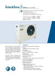
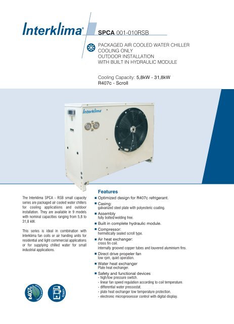
<strong>SPCA</strong> <strong>001</strong>-<strong>010RSB</strong><br />
PACKAGED AIR COOLED WATER CHILLER<br />
COOLING ONLY<br />
OUTDOOR INSTALLATION<br />
WITH BUILT IN HYDRAULIC MODULE<br />
Cooling Capacity: 5,8kW - 31,8kW<br />
R407c - Scroll<br />
The Interklima <strong>SPCA</strong> - RSB small capacity<br />
series are packaged air cooled water chillers<br />
for cooling applications and outdoor<br />
installation. They are available in 9 models<br />
with nominal capacities ranging from 5,8 to<br />
31,8 kW.<br />
This series is ideal in combination with<br />
Interklima fan coils or air handing units for<br />
residential and light commercial applications<br />
or for supplying chilled water for small<br />
industrial applications.<br />
Features<br />
Optimized design for R407c refrigerant.<br />
Casing:<br />
galvanized steel plate with polyesteric coating.<br />
Assembly<br />
fully bolted/welding free.<br />
Built in complete hydraulic module.<br />
Compressor:<br />
hermetically sealed scroll type.<br />
Air heat exchanger:<br />
cross fin coil.<br />
internally grooved copper tubes and louvered aluminium fins.<br />
Direct drive propeler fan<br />
low rpm, quiet operation.<br />
Water heat exchanger<br />
Plate heat exchanger.<br />
Safety and functional devices<br />
- high/low pressure switch.<br />
- linear fan speed regulation according to coil temperature.<br />
- differential water pressostat.<br />
- plate heat exchanger low temperature protection.<br />
- electronic microprosessor control with digital display.
NOMENCLATURE<br />
1 Range<br />
S-small M-mid L-large R-screw-series<br />
2 Packaged Chiller Air-cooled<br />
PCA<br />
3 Model number<br />
<strong>001</strong>-002-003-004-005-006-007-010<br />
4 Cool / Heat Model<br />
R-cooling only H-heat pump<br />
5 Compressor type<br />
S-scroll M-tandem scroll R-reciprocating<br />
T-twin screw<br />
6 Refrigerant type<br />
A-R22 B-R407c<br />
7 Electrical Characteristic<br />
-1 Single phase -Ommited Three phase
Contents<br />
1.Technical Description<br />
2. Specifications<br />
3. Capacity Tables<br />
4. Available External Water<br />
Pressure Curves<br />
5. Operation Range<br />
6. Sound Data<br />
7. Outlook Drawings<br />
8. Refrigerant Circuit Diagrams<br />
9. Wiring Diagrams<br />
10. Installation<br />
11. Guide Specifications<br />
Interklima Hydronic systems<br />
<strong>SPCA</strong> <strong>001</strong>-<strong>010RSB</strong> ñ R407c/Scroll 3
1. Technical Description<br />
General<br />
The <strong>SPCA</strong>-RSB series air-cooled water chillers consists of 9<br />
models covering capacities from 5,8 up to 31,8kW.<br />
It is the end result of a thorough study, and accurate design by<br />
experienced Interklima research and development teams, to<br />
develop a small size chiller series with compact shape, high<br />
performance, and reliability of the highest quality standards.<br />
This series meets the highest levels of aesthetic and technical<br />
requirements using the latest technological innovations including<br />
environmentally friendly R407c refrigerant that is Chlorine-free<br />
and has zero ozone depletion potential. <strong>SPCA</strong>-RSB units are<br />
therefore ideal for installation in urban environments due to their<br />
elegant design, selected materials and low operating sound levels.<br />
Casing<br />
All units use metal parts fabricated from heavy gauge galvanized<br />
steel sheets, formed to ensure maximum rigidity that guarantees and<br />
preserves the units operation during the years. After fabrication metal<br />
parts are degreased, phosphatised, and electrostatically powder<br />
coated with an epoxy-polyester RAL 9002 coating of a thickness of<br />
60-70Ì. This fully automatic process ensures superior corrosion<br />
resistance against the most aggressive ambient conditions. The<br />
treatment can successfully withstand a salt spray test of 500 hours,<br />
according to ASTM B-117.<br />
All components are assembled together using bolts thus avoiding<br />
the need for welding which may harm the galvanization of the<br />
steel, and ensures that the whole assembly can fully withstand<br />
adverse weather conditions.<br />
The compact footprint of the unit arises from detailed study and<br />
design by our engineering teams and results in a machine, which<br />
fits easily in restricted areas and is simple and easy to install and<br />
maintain, and has been designed with special fittings for easy<br />
transport and lifting.<br />
Removable panels with special locks are used to permit access only<br />
to authorized personnel to internal components of the unit for<br />
inspection and maintenance.<br />
Compressor<br />
All units' use low-noise, maintenance free, Hermetic Scroll<br />
compressor with low vibration levels, specially optimized for use<br />
with R407c refrigerant, selected from world class suppliers.<br />
They are equipped with a crankcase electrical heater for the oil,<br />
and are internally protected against potential overloading or<br />
electrical spikes.<br />
The compressors are mounted on special antivibration rubber<br />
mounts to eliminate vibration from the unit's operation.<br />
Hydraulic kit<br />
All units are equipped, as standard, with a complete hydraulic kit<br />
comprising of a circulating pump, buffer and expansion tank,<br />
automatic fill and make up water valve with manometer, safety<br />
valve, airvent, water filter, differential water pressure switch, and<br />
evacuation valve.<br />
Condenser coil<br />
All unit air heat exchangers are manufactured from high quality inner<br />
grooved seamless copper tubes according to ASTM B-280, having<br />
an outside diameter of 9,52 mm (3/8"). The fins are manufactured<br />
from aluminium and form the secondary extended heat transfer<br />
surface. The fins are continuous across the heat exchanger and are<br />
fabricated in high precision dedicated press lines. The fin surface is<br />
waffle formed, so as to increase the fin rigidity, and have special<br />
louvers that help increase heat transfer. The combination of<br />
internally grooved Copper-tubing and louvered fins has resulted in a<br />
heat transfer performance 30% superior to that of a conventional<br />
coil for this particular application. The assembly of the finned pack<br />
is achieved by mechanical expansion of the tubes in such a way as<br />
to form a perfect mechanical bond with the fins. For this purpose,<br />
the fin holes have a peripheral extrusion (collar) of adjustable height.<br />
This extrusion serves to define the distance between fins (and<br />
consequently the total heat transfer surface) and to ensure perfect<br />
contact of the fins to the tubes.<br />
Alternative fin materials are available upon request such as epoxy<br />
- coated aluminium or copper for applications in especially<br />
aggressive environments.<br />
Evaporator<br />
All units are equiped with a water - refrigerant Plate Heat<br />
Exchanger, selected from world class manufacturers.<br />
It is made of stainless steel plates (AISI 3161.4401) specially<br />
formed to achieved a large heat transfer surface and assembled<br />
by means of an automatic brazing proccess under vaccum.<br />
Condenser fans<br />
All unit fans are of the axial type, single phase, 6 poles, internally<br />
protected against potential overheating, silent and suitable for<br />
outdoor installation. Due to the sophisticated aerodynamic design<br />
of the blades and inlet cones, as well as the perfect static and<br />
dynamic balancing, their operation is completely vibration-free. The<br />
fan-motor assembly has a protective grid against accidental<br />
contact with moving parts, which is designed according to ISO<br />
regulations. Fan motors are of the external rotor type,<br />
aerodynamically shaped so as not to interfere with the airflow, and<br />
4<br />
Interklima Hydronic systems<br />
<strong>SPCA</strong> <strong>001</strong>-<strong>010RSB</strong> ñ R407c/Scroll
have permanently lubricated bearings that do not require servicing.<br />
Continuous linear fan speed regulation control is achieved<br />
according to coil temperatures including fan silent mode operation.<br />
This standard feature for Interklima <strong>SPCA</strong> units saves energy and<br />
reduces sound levels dramatically, optimizing capacity.<br />
Microprocessor controller<br />
All units are equipped with a sophisticated controller easily<br />
accessible from outside through a transparent plastic cover that<br />
combines intelligence with operating simplicity. The controller<br />
constantly monitors all machine parameters and precisely<br />
manages among others:<br />
ñ Automatic compressor control function through return water<br />
temperature.<br />
ñ Continuous fan speed control based on coil heat exchanger<br />
temperature.<br />
ñ Hydraulic circuit pump control.<br />
ñ Compressor start up time delay function.<br />
ñ Over 150 programmable parameters.<br />
ñ Fan motor overload protection.<br />
ñ Auto diagnostic stop function due to low water circulation,<br />
high/low operating pressures, and compressor thermal<br />
overload.<br />
ñ Auto diagnostic function and digital display of approximately<br />
30 possible error codes including thermistor faults.<br />
ñ Digital displays of water inlet / outlet as well as coil<br />
temperatures.<br />
ñ Remote on/ off switch.<br />
ñ Remote alarm indication capability.<br />
ñ Many optional control capabilities (listed in optional<br />
accessories).<br />
Optional accessories<br />
Microprocessor controller options<br />
ñ Remote keyboard.<br />
ñ Dynamic set point program via a 4-20ma proportional signal<br />
ñ BMS module interface kit for Modbus connection.<br />
ñ Parallel chiller operation with more than 2 units with optional<br />
controller.<br />
ñ Microprocessor parameter reprogramming card.<br />
Other unit accessories/option<br />
ñ R407c or R22 refrigerant.<br />
ñ Antifreeze protection.<br />
ñ Condenser fins made of copper or prepainted aluminum, or<br />
blygold treatment for corrosion protection.<br />
ñ Glycol application for chilled water temperature down to -5 o C.<br />
ñ Pressure relief valve on compressor discharge.<br />
ñ High / Low pressure manometers.<br />
ñ Phase sequence - phase failure - reverse phase and voltage<br />
monitoring device.<br />
ñ Compressor noise reduction jacket.<br />
ñ Compressor chamber noise reduction kit.<br />
ñ Other custom built options upon request.<br />
Refrigerant circuit<br />
All units have a single refrigerant circuit with one compressor.The<br />
circuit consists, depending on the size, of either a capillary or<br />
thermal expansion valve. Other components fitted are solenoid<br />
valve, and a large capacity filter dryer.<br />
Unit protection is provided by a high-pressure switch with manual<br />
reset, low-pressure protection is via a low-pressure switch.<br />
Interklima Hydronic systems<br />
<strong>SPCA</strong> <strong>001</strong>-<strong>010RSB</strong> ñ R407c/Scroll 5
2. Technical specifications<br />
2.1 <strong>SPCA</strong> <strong>001</strong>-<strong>010RSB</strong><br />
Type<br />
Nominal cooling capacity<br />
Construction<br />
Compressor<br />
Quantity<br />
Absorbed power<br />
Nominal operating current<br />
Maximum operating current<br />
Air heat exchanger<br />
Water heat exchanger<br />
Quantity<br />
Water content<br />
Max. Operating pressure<br />
Connections<br />
Nominal water flow<br />
Water pressure drop<br />
Minimum system water content<br />
Maximum unit operating water pressure<br />
Fan<br />
Quantity<br />
Speed<br />
Total air flow<br />
Absorbed power<br />
Nominal operating current<br />
Maximum operating current<br />
Pump<br />
Absorbed power<br />
Maximum operating current<br />
Available external water head<br />
Electrical characteristics<br />
Total absorbed power<br />
Nominal operating current<br />
Maximum operating current<br />
Compressor carter resistance power<br />
Power cables cross section<br />
Fuses<br />
Voltage operating limits<br />
Refrigerant circuit<br />
Number of circuits<br />
Expansion device<br />
Refrigerant type<br />
Noise level at 5m<br />
Dimensions<br />
Shipping weight<br />
kW<br />
RT<br />
Btu/h<br />
Material/Color<br />
kW<br />
A<br />
A<br />
l<br />
Water side bar<br />
Refrigerant side bar<br />
l/h<br />
kpa<br />
l<br />
bar<br />
rpm<br />
m 3 /h<br />
kW<br />
A<br />
A<br />
kW<br />
A<br />
Kpa<br />
kW<br />
A<br />
A<br />
W<br />
mm 2 A<br />
V<br />
dB(A)<br />
Width mm<br />
Length mm<br />
Heigth mm<br />
kg<br />
<strong>SPCA</strong>-<strong>001</strong>-1 <strong>SPCA</strong>-002-1 <strong>SPCA</strong>-002 <strong>SPCA</strong>-003 <strong>SPCA</strong>-004<br />
5,8<br />
1,6<br />
19.773<br />
1<br />
2,00<br />
9,40<br />
14,80<br />
1<br />
0,57<br />
30<br />
30<br />
3/4"<br />
998<br />
26,5<br />
29<br />
3,0<br />
1<br />
920<br />
2.500<br />
0,12<br />
0,57<br />
0,63<br />
0,13<br />
0,58<br />
35,0<br />
2,3<br />
10,6<br />
16,0<br />
70<br />
4<br />
25<br />
1<br />
45<br />
474<br />
1022<br />
932<br />
100<br />
6,9<br />
2,0<br />
23.523<br />
1<br />
2,40<br />
11,10<br />
17,30<br />
1<br />
0,66<br />
30<br />
30<br />
3/4"<br />
1.187<br />
27,6<br />
35<br />
3,0<br />
6,9<br />
2,0<br />
23.523<br />
1<br />
2,32<br />
4,40<br />
5,60<br />
Brazed plate<br />
1<br />
0,66<br />
30<br />
30<br />
3/4"<br />
1.187<br />
27,6<br />
35<br />
3,0<br />
Axial type<br />
8,1<br />
2,3<br />
27.614<br />
Galvanized steel / Light grey-beige (RAL 9002)<br />
SCROLL<br />
1<br />
920<br />
2.350<br />
0,12<br />
0,57<br />
0,63<br />
0,13<br />
0,58<br />
32,0<br />
2,7<br />
12,3<br />
18,5<br />
70<br />
4<br />
25<br />
1<br />
45<br />
474<br />
1022<br />
932<br />
108<br />
1<br />
920<br />
2.350<br />
0,12<br />
0,57<br />
0,63<br />
0,13<br />
0,58<br />
32,0<br />
2,6<br />
5,6<br />
6,8<br />
70<br />
2,5<br />
3x16<br />
1<br />
Capillary tubes<br />
R407c<br />
46<br />
474<br />
1022<br />
932<br />
108<br />
1<br />
2,70<br />
5,00<br />
7,00<br />
1<br />
0,76<br />
30<br />
30<br />
1"<br />
1.393<br />
29,2<br />
41<br />
3,0<br />
1<br />
920<br />
4.000<br />
0,17<br />
0,80<br />
0,90<br />
0,13<br />
0,58<br />
30,0<br />
3,0<br />
6,4<br />
8,5<br />
70<br />
2,5<br />
3x16<br />
1<br />
48<br />
474<br />
1222<br />
982<br />
140<br />
12,2<br />
3,5<br />
41.591<br />
1<br />
4,02<br />
7,80<br />
11,00<br />
High capacity cross finned coil with internally grooved tubes and louver fins<br />
230 V/1 ph/50 Hz 400 V/3 ph/50 Hz<br />
220-240 V<br />
360-440 V<br />
1<br />
1,14<br />
30<br />
30<br />
1"<br />
2.098<br />
29,9<br />
61<br />
3,0<br />
2<br />
920<br />
4.600<br />
0,24<br />
1,14<br />
1,26<br />
0,25<br />
1,1<br />
42,0<br />
4,5<br />
10,0<br />
13,4<br />
70<br />
2,5<br />
3x16<br />
1<br />
48<br />
522<br />
1462<br />
1002<br />
180<br />
6<br />
Interklima Hydronic systems<br />
<strong>SPCA</strong> <strong>001</strong>-<strong>010RSB</strong> ñ R407c/Scroll
Type<br />
Nominal cooling capacity<br />
Construction<br />
Compressor<br />
Quantity<br />
Absorbed power<br />
Nominal operating current<br />
Maximum operating current<br />
Air heat exchanger<br />
Water heat exchanger<br />
Quantity<br />
Water content<br />
Max. Operating pressure<br />
Connections<br />
Nominal water flow<br />
Water pressure drop<br />
Minimum system water content<br />
Maximum unit operating water pressure<br />
Fan<br />
Quantity<br />
Speed<br />
Total air flow<br />
Absorbed power<br />
Nominal operating current<br />
Maximum operating current<br />
Pump<br />
Absorbed power<br />
Maximum operating current<br />
Available external water head<br />
Electrical characteristics<br />
Total absorbed power<br />
Nominal operating current<br />
Maximum operating current<br />
Compressor carter resistance power<br />
Power cables cross section<br />
Fuses<br />
Voltage operating limits<br />
Refrigerant circuit<br />
Number of circuits<br />
Expansion device<br />
Refrigerant type<br />
Noise level at 5m<br />
Dimensions<br />
Shipping weight<br />
kW<br />
RT<br />
Btu/h<br />
Material/Color<br />
kW<br />
A<br />
A<br />
l<br />
Water side bar<br />
Refrigerant side bar<br />
l/h<br />
kpa<br />
l<br />
bar<br />
rpm<br />
m 3 /h<br />
kW<br />
A<br />
A<br />
kW<br />
A<br />
Kpa<br />
kW<br />
A<br />
A<br />
W<br />
mm 2 A<br />
V<br />
dB(A)<br />
Width mm<br />
Length mm<br />
Heigth mm<br />
kg<br />
<strong>SPCA</strong>-005 <strong>SPCA</strong>-006 <strong>SPCA</strong>-007 <strong>SPCA</strong>-010<br />
14,6<br />
4,14<br />
49.773<br />
1<br />
4,70<br />
8,30<br />
13,00<br />
1<br />
1,35<br />
30<br />
30<br />
1"<br />
2.511<br />
34,1<br />
73<br />
3,0<br />
2<br />
920<br />
6.200<br />
0,34<br />
1,60<br />
1,80<br />
0,30<br />
2,00<br />
130,0<br />
5,3<br />
11,9<br />
16,8<br />
70<br />
4<br />
3x25<br />
1<br />
Capillary tubes<br />
51<br />
522<br />
1612<br />
1002<br />
200<br />
18,5<br />
5,36<br />
63.068<br />
1<br />
6,00<br />
12,20<br />
17,00<br />
1<br />
1,40<br />
30<br />
30<br />
1 1/4"<br />
3.182<br />
34,6<br />
93<br />
3,0<br />
2<br />
920<br />
6.400<br />
0,34<br />
1,60<br />
1,80<br />
0,45<br />
2,70<br />
150,0<br />
6,8<br />
16,5<br />
21,5<br />
70<br />
6<br />
3x25<br />
22,4<br />
6,47<br />
76.364<br />
Galvanized steel / Light grey-beige (RAL 9002)<br />
SCROLL<br />
1<br />
7,20<br />
14,50<br />
20,00<br />
1<br />
1,70<br />
30<br />
30<br />
1 1/4"<br />
3.853<br />
45,4<br />
112<br />
3,0<br />
31,8<br />
9,010<br />
108.409<br />
1<br />
10,30<br />
17,80<br />
27,00<br />
High capacity cross finned coil with internally grooved tubes and louver fins<br />
Brazed plate<br />
1<br />
2,50<br />
30<br />
30<br />
1 1/4"<br />
5.470<br />
24,4<br />
159<br />
3,0<br />
1<br />
1<br />
1<br />
Expansion valve / Capillary tubes<br />
R407c<br />
52<br />
605<br />
1732<br />
1202<br />
270<br />
Axial type<br />
2<br />
920<br />
10.500<br />
0,74<br />
3,40<br />
3,80<br />
0,45<br />
2,70<br />
120,0<br />
400 V/3 ph/50 Hz<br />
360-440 V<br />
8,4<br />
20,6<br />
26,5<br />
70<br />
6<br />
3x32<br />
53<br />
800<br />
2020<br />
1202<br />
320<br />
2<br />
920<br />
11.000<br />
0,74<br />
3,40<br />
3,80<br />
0,55<br />
3,50<br />
165,0<br />
11,6<br />
24,7<br />
34,3<br />
70<br />
10<br />
3x40<br />
55<br />
800<br />
2020<br />
1202<br />
350<br />
NOTES<br />
Nominal conditions are as<br />
follows<br />
entering/leaving chilled<br />
water temperature 12/7oC;<br />
ambient 35oC DB<br />
electrical installation<br />
specifications are purely<br />
indicative and non-binding,<br />
all connections to the<br />
system and the electrical<br />
installation must be in full<br />
accordance with all<br />
applicable national and local<br />
codes.<br />
Interklima Hydronic systems<br />
<strong>SPCA</strong> <strong>001</strong>-<strong>010RSB</strong> ñ R407c/Scroll 7
Interklima Hydronic systems<br />
<strong>SPCA</strong> <strong>001</strong>-<strong>010RSB</strong> ñ R407c/Scroll<br />
8<br />
3. Capacity tables<br />
<strong>SPCA</strong>-<strong>001</strong>-1<br />
<strong>SPCA</strong>-002-1<br />
<strong>SPCA</strong>-002<br />
<strong>SPCA</strong>-003<br />
<strong>SPCA</strong>-004<br />
<strong>SPCA</strong>-005<br />
<strong>SPCA</strong>-006<br />
<strong>SPCA</strong>-007<br />
<strong>SPCA</strong>-010<br />
Water<br />
outlet ÆC<br />
Cooling<br />
capacity<br />
kW<br />
Absorbed<br />
power<br />
kW<br />
Current<br />
A<br />
Absorbed<br />
power<br />
kW<br />
Current<br />
A<br />
Cooling<br />
capacity<br />
kW<br />
Absorbed<br />
power<br />
kW<br />
Current<br />
A<br />
Cooling<br />
capacity<br />
kW<br />
Absorbed<br />
power<br />
kW<br />
Current<br />
A<br />
Cooling<br />
capacity<br />
kW<br />
Absorbed<br />
power<br />
kW<br />
25 30 35 40 45<br />
Current<br />
A<br />
Cooling<br />
capacity<br />
kW<br />
5<br />
7<br />
10<br />
5<br />
7<br />
10<br />
5<br />
7<br />
10<br />
5<br />
7<br />
10<br />
5<br />
7<br />
10<br />
5<br />
7<br />
10<br />
5<br />
7<br />
10<br />
5<br />
7<br />
10<br />
5<br />
7<br />
10<br />
6.1<br />
6.7<br />
7.5<br />
7.3<br />
8.0<br />
8.9<br />
7.2<br />
7.9<br />
8.8<br />
8.5<br />
9.2<br />
10.4<br />
12.8<br />
14.0<br />
15.7<br />
15.4<br />
16.7<br />
18.7<br />
19.3<br />
21.0<br />
23.6<br />
23.5<br />
25.4<br />
28.4<br />
33.4<br />
36.1<br />
40.4<br />
1.6<br />
1.6<br />
1.6<br />
1.9<br />
1.9<br />
1.8<br />
1.8<br />
1.8<br />
1.8<br />
2.1<br />
2.1<br />
2.1<br />
3.2<br />
3.2<br />
3.2<br />
3.7<br />
3.7<br />
3.7<br />
4.7<br />
4.7<br />
4.7<br />
5.7<br />
5.7<br />
5.7<br />
8.1<br />
8.1<br />
8.2<br />
7.5<br />
7.5<br />
7.4<br />
8.9<br />
8.8<br />
8.7<br />
3.8<br />
3.7<br />
3.7<br />
4.3<br />
4.3<br />
4.3<br />
6.9<br />
6.9<br />
6.9<br />
6.9<br />
6.9<br />
7.0<br />
10.9<br />
10.9<br />
10.9<br />
13.0<br />
13.0<br />
13.0<br />
15.1<br />
15.2<br />
15.2<br />
5.8<br />
6.2<br />
7.0<br />
6.9<br />
7.5<br />
8.4<br />
6.8<br />
7.4<br />
8.3<br />
8.0<br />
8.7<br />
9.8<br />
12.1<br />
13.1<br />
14.8<br />
14.5<br />
15.6<br />
17.5<br />
18.2<br />
19.7<br />
22.2<br />
22.1<br />
23.9<br />
26.8<br />
31.5<br />
34.0<br />
38.1<br />
1.8<br />
1.8<br />
1.8<br />
2.1<br />
2.1<br />
2.1<br />
2.1<br />
2.0<br />
2.0<br />
2.4<br />
2.4<br />
2.4<br />
3.6<br />
3.6<br />
3.6<br />
4.1<br />
4.1<br />
4.1<br />
5.3<br />
5.3<br />
5.3<br />
6.4<br />
6.4<br />
6.4<br />
9.1<br />
9.1<br />
9.1<br />
8.4<br />
8.3<br />
8.2<br />
9.9<br />
9.9<br />
9.8<br />
4.1<br />
4.0<br />
4.0<br />
4.7<br />
4.6<br />
4.6<br />
7.3<br />
7.3<br />
7.3<br />
7.6<br />
7.6<br />
7.6<br />
11.5<br />
11.5<br />
11.5<br />
13.7<br />
13.7<br />
13.6<br />
16.3<br />
16.3<br />
16.4<br />
5.4<br />
5.8<br />
6.6<br />
6.4<br />
6.9<br />
7.8<br />
6.3<br />
6.9<br />
7.8<br />
7.4<br />
8.1<br />
9.2<br />
11.2<br />
12.2<br />
13.9<br />
13.5<br />
14.6<br />
16.4<br />
17.0<br />
18.5<br />
20.8<br />
20.7<br />
22.4<br />
25.2<br />
29.5<br />
31.8<br />
35.7<br />
2.0<br />
2.0<br />
2.0<br />
2.4<br />
2.4<br />
2.3<br />
2.3<br />
2.3<br />
2.3<br />
2.7<br />
2.7<br />
2.7<br />
4.0<br />
4.0<br />
4.0<br />
4.7<br />
4.7<br />
4.7<br />
6.0<br />
6.0<br />
5.9<br />
7.2<br />
7.2<br />
7.2<br />
10.2<br />
10.3<br />
10.3<br />
9.4<br />
9.4<br />
9.2<br />
11.1<br />
11.1<br />
10.9<br />
4.4<br />
4.4<br />
4.4<br />
5.1<br />
5.0<br />
5.0<br />
7.7<br />
7.8<br />
7.8<br />
8.3<br />
8.3<br />
8.3<br />
12.2<br />
12.2<br />
12.2<br />
14.5<br />
14.5<br />
14.5<br />
17.7<br />
17.8<br />
17.8<br />
4.9<br />
5.4<br />
6.1<br />
5.9<br />
6.4<br />
7.2<br />
5.8<br />
6.4<br />
7.2<br />
6.9<br />
7.5<br />
8.5<br />
10.4<br />
11.3<br />
12.9<br />
12.5<br />
13.6<br />
15.2<br />
15.8<br />
17.2<br />
19.5<br />
19.3<br />
20.9<br />
23.5<br />
27.4<br />
29.6<br />
33.3<br />
2.3<br />
2.3<br />
2.3<br />
2.7<br />
2.7<br />
2.7<br />
2.7<br />
2.6<br />
2.6<br />
3.1<br />
3.1<br />
3.1<br />
4.5<br />
4.5<br />
4.5<br />
5.2<br />
5.2<br />
5.2<br />
6.8<br />
6.8<br />
6.7<br />
8.0<br />
8.0<br />
8.1<br />
11.5<br />
11.5<br />
11.6<br />
10.6<br />
10.6<br />
10.4<br />
12.6<br />
12.5<br />
12.4<br />
4.8<br />
4.8<br />
4.8<br />
5.5<br />
5.5<br />
5.5<br />
8.3<br />
8.3<br />
8.3<br />
9.2<br />
9.2<br />
9.2<br />
13.1<br />
13.1<br />
13.1<br />
15.5<br />
15.5<br />
15.5<br />
19.4<br />
19.4<br />
19.4<br />
4.5<br />
4.9<br />
5.5<br />
5.3<br />
5.8<br />
6.6<br />
5.3<br />
5.8<br />
6.6<br />
6.3<br />
6.8<br />
7.8<br />
9.5<br />
10.4<br />
11.8<br />
11.5<br />
12.5<br />
14.1<br />
14.7<br />
16.0<br />
18.1<br />
17.9<br />
19.4<br />
21.9<br />
25.3<br />
27.4<br />
30.8<br />
2.6<br />
2.6<br />
2.6<br />
3.1<br />
3.1<br />
3.0<br />
3.0<br />
3.0<br />
3.0<br />
3.5<br />
3.5<br />
3.5<br />
5.0<br />
5.0<br />
5.0<br />
5.9<br />
5.9<br />
5.9<br />
7.7<br />
7.7<br />
7.7<br />
9.0<br />
9.0<br />
9.0<br />
13.0<br />
13.0<br />
13.0<br />
12.1<br />
12.0<br />
11.9<br />
14.3<br />
14.2<br />
14.1<br />
5.3<br />
5.3<br />
5.3<br />
6.1<br />
6.1<br />
6.0<br />
8.9<br />
8.9<br />
9.0<br />
10.2<br />
10.2<br />
10.2<br />
14.1<br />
14.1<br />
14.1<br />
16.6<br />
16.6<br />
16.6<br />
21.3<br />
21.3<br />
21.4<br />
Type<br />
Ambient temperature o C<br />
Cooling capacity table for <strong>SPCA</strong> <strong>001</strong>-<strong>010RSB</strong><br />
NOTES<br />
Bold values show nominal cooling capacities<br />
Absorbed power and current refers to the compressor<br />
Above figures are valid for water ¢t = 5 o C
4. Available external water pressure curves<br />
<strong>SPCA</strong> <strong>001</strong>-<strong>010RSB</strong><br />
PD<br />
90<br />
80<br />
70<br />
60<br />
kpa<br />
50<br />
40<br />
004<br />
30<br />
20<br />
10<br />
<strong>001</strong><br />
003<br />
002<br />
0 0 500 1.000 1.500 2.000 2.500 3.000 3.500 WF<br />
l/h<br />
PD<br />
kpa<br />
360<br />
340<br />
320<br />
300<br />
280<br />
260<br />
240<br />
220<br />
010<br />
200<br />
180<br />
160<br />
007<br />
140<br />
006<br />
120<br />
100<br />
80<br />
005<br />
60<br />
40<br />
20<br />
0 0 500 1,000 1,500 2.000 2.500 3.000 3.500 4.000 4.500 5.000 5.500 6.000 WF<br />
l/h<br />
NOTES<br />
PD: pressure drop<br />
WF: water flow rate<br />
1. <strong>SPCA</strong> <strong>001</strong>-002RSB<br />
2. <strong>SPCA</strong> 003RSB<br />
3. <strong>SPCA</strong> 004RSB<br />
4. <strong>SPCA</strong> 005RSB<br />
5. <strong>SPCA</strong> 006RSB<br />
6. <strong>SPCA</strong> 007-<strong>010RSB</strong><br />
ETHYLENE GLYCOL CORRECTION FACTORS<br />
% ETHYLENE GLYCOL BY VOLUME<br />
Freezing point<br />
o C<br />
Output duty<br />
kW<br />
Input power<br />
kW<br />
Equivalent Flow rate<br />
L/H<br />
Equivalent Pressure drop kPa<br />
UNIT 10<br />
-4<br />
0,99<br />
0,99<br />
1,02<br />
1,06<br />
20<br />
-9<br />
0,98<br />
0,98<br />
1,04<br />
1,12<br />
30<br />
-15<br />
0,97<br />
0,98<br />
1,08<br />
1,18<br />
40<br />
-23<br />
0,96<br />
0,97<br />
1,13<br />
1,25<br />
Interklima Hydronic systems<br />
<strong>SPCA</strong> <strong>001</strong>-<strong>010RSB</strong> ñ R407c/Scroll 9
5. Operation range<br />
O<br />
Outdoor Temperature ( CDB)<br />
47<br />
45<br />
NOTES<br />
Protect the water circuit against freezing<br />
4<br />
0<br />
-5<br />
6 15<br />
Leaving water<br />
temperature( o C)<br />
- The accompanying operating limits are for general guidance only.<br />
It may be possible for certain units to operate outside the confines<br />
of the graph. Please contact Interklima if further clarification is<br />
required.<br />
- For operation with leaving water temperature below 6 o C it is<br />
required to confirm with Interklima at the time of order and the<br />
addition of glycol into the system.<br />
6. Sound data<br />
Type<br />
Octave band center frequency (Hz)<br />
<strong>SPCA</strong> - <strong>001</strong><br />
<strong>SPCA</strong> - 002<br />
<strong>SPCA</strong> - 003<br />
<strong>SPCA</strong> - 004<br />
<strong>SPCA</strong> - 005<br />
<strong>SPCA</strong> - 006<br />
<strong>SPCA</strong> - 007<br />
<strong>SPCA</strong> - 010<br />
Power<br />
Pressure @1 m<br />
Pressure @10 m<br />
Power<br />
Pressure @1 m<br />
Pressure @10 m<br />
Power<br />
Pressure @1 m<br />
Pressure @10 m<br />
Power<br />
Pressure @1 m<br />
Pressure @10 m<br />
Power<br />
Pressure @1 m<br />
Pressure @10 m<br />
Power<br />
Pressure @1 m<br />
Pressure @10 m<br />
Power<br />
Pressure @1 m<br />
Pressure @10 m<br />
Power<br />
Pressure @1 m<br />
Pressure @10 m<br />
dB(A)<br />
66<br />
58<br />
39<br />
67<br />
59<br />
39<br />
68<br />
60<br />
40<br />
70<br />
62<br />
42<br />
71<br />
64<br />
44<br />
74<br />
66<br />
46<br />
75<br />
67<br />
47<br />
77<br />
69<br />
49<br />
63<br />
49<br />
41<br />
21<br />
49<br />
41<br />
21<br />
51<br />
43<br />
23<br />
52<br />
44<br />
24<br />
54<br />
46<br />
26<br />
54<br />
46<br />
26<br />
54<br />
46<br />
26<br />
54<br />
46<br />
26<br />
125<br />
55<br />
47<br />
27<br />
55<br />
47<br />
27<br />
56<br />
48<br />
28<br />
58<br />
50<br />
30<br />
59<br />
51<br />
31<br />
59<br />
51<br />
31<br />
60<br />
52<br />
32<br />
60<br />
52<br />
32<br />
250<br />
56<br />
48<br />
28<br />
56<br />
48<br />
28<br />
57<br />
49<br />
29<br />
59<br />
51<br />
31<br />
60<br />
52<br />
32<br />
61<br />
53<br />
33<br />
60<br />
52<br />
32<br />
61<br />
53<br />
33<br />
500<br />
58<br />
50<br />
30<br />
58<br />
50<br />
30<br />
59<br />
51<br />
31<br />
61<br />
53<br />
33<br />
61<br />
53<br />
33<br />
69<br />
61<br />
41<br />
69<br />
61<br />
41<br />
70<br />
62<br />
42<br />
1000<br />
62<br />
54<br />
34<br />
62<br />
56<br />
36<br />
64<br />
56<br />
36<br />
65<br />
57<br />
37<br />
67<br />
59<br />
39<br />
68<br />
60<br />
40<br />
68<br />
60<br />
40<br />
69<br />
61<br />
41<br />
2000<br />
59<br />
51<br />
31<br />
61<br />
55<br />
35<br />
62<br />
54<br />
34<br />
63<br />
55<br />
35<br />
64<br />
56<br />
36<br />
67<br />
59<br />
39<br />
70<br />
62<br />
42<br />
73<br />
65<br />
45<br />
4000<br />
54<br />
46<br />
26<br />
58<br />
53<br />
33<br />
58<br />
50<br />
30<br />
58<br />
50<br />
30<br />
65<br />
57<br />
37<br />
63<br />
55<br />
35<br />
65<br />
57<br />
37<br />
70<br />
62<br />
42<br />
8000<br />
49<br />
41<br />
21<br />
48<br />
42<br />
22<br />
49<br />
41<br />
21<br />
50<br />
42<br />
22<br />
53<br />
45<br />
25<br />
50<br />
42<br />
22<br />
50<br />
42<br />
22<br />
57<br />
49<br />
29<br />
10<br />
Interklima Hydronic systems<br />
<strong>SPCA</strong> <strong>001</strong>-<strong>010RSB</strong> ñ R407c/Scroll
7. Outlook drawings<br />
7.1 <strong>SPCA</strong> <strong>001</strong>-002RSB<br />
474<br />
460<br />
1022<br />
1008<br />
932<br />
450<br />
7.2 <strong>SPCA</strong> 003RSB<br />
474<br />
460<br />
49<br />
1000<br />
1222<br />
1208<br />
981<br />
450<br />
7.3 <strong>SPCA</strong> 004RSB<br />
522<br />
508<br />
51<br />
1200<br />
1462<br />
1448<br />
1002<br />
500<br />
1440<br />
7.4 <strong>SPCA</strong> 005RSB<br />
522 1612<br />
508<br />
1598<br />
1002<br />
500<br />
1590<br />
Interklima Hydronic systems<br />
<strong>SPCA</strong> <strong>001</strong>-<strong>010RSB</strong> ñ R407c/Scroll 11
0 m m<br />
1<br />
m a x .<br />
w<br />
r e<br />
c<br />
s<br />
f<br />
o<br />
R<br />
De pt h<br />
E i s c<br />
n<br />
h r<br />
a<br />
u b<br />
Mulfingen<br />
Germany<br />
t ie<br />
f e<br />
m a<br />
x<br />
.<br />
1<br />
0 m m<br />
0 m m<br />
1<br />
m a x .<br />
w<br />
r e<br />
c<br />
s<br />
f<br />
o<br />
R<br />
De pt h<br />
E i s c<br />
n<br />
h r<br />
a<br />
u b<br />
Mulfingen<br />
Germany<br />
t ie<br />
f e<br />
m a<br />
x<br />
.<br />
1<br />
0 m m<br />
519<br />
7.5 <strong>SPCA</strong> 006RSB<br />
1754<br />
1740<br />
50<br />
1202<br />
605<br />
40<br />
1732<br />
7.6 <strong>SPCA</strong> 007-<strong>010RSB</strong><br />
2042<br />
2028<br />
137<br />
1202<br />
800<br />
40 2020<br />
12<br />
Interklima Hydronic systems<br />
<strong>SPCA</strong> <strong>001</strong>-<strong>010RSB</strong> ñ R407c/Scroll
8. Refrigerant circuit diagrams<br />
8.1 <strong>SPCA</strong> <strong>001</strong>-005RSB<br />
3<br />
4<br />
2<br />
1<br />
5.1<br />
8.2 <strong>SPCA</strong> 006-<strong>010RSB</strong><br />
3 3<br />
4<br />
2<br />
1<br />
6<br />
5.2<br />
NOTES<br />
1. Compressor<br />
2. Plate heat exchanger<br />
3. Condenser coil<br />
4. Filter dryer<br />
5.1 Capillary<br />
5.2 Thermal expansion valve<br />
6. Solenoid valve<br />
Interklima Hydronic systems<br />
<strong>SPCA</strong> <strong>001</strong>-<strong>010RSB</strong> ñ R407c/Scroll 13
9. Wiring diagrams<br />
9.1 <strong>SPCA</strong> <strong>001</strong>-002RSB-1<br />
SM1<br />
ALARM OUTPUT<br />
grd<br />
grd<br />
grd<br />
L<br />
N<br />
PE<br />
AL<br />
AL<br />
12AC ALL GND GND<br />
12AC 12DC TK1 ID5<br />
ST4<br />
ID4<br />
S3<br />
ST3<br />
ID3<br />
S2<br />
ST2<br />
ID2<br />
S1<br />
ST1<br />
ID1<br />
F 2A<br />
ON<br />
F<br />
L<br />
H<br />
ENERGY 210<br />
CC<br />
CC<br />
12V<br />
12V<br />
TR<br />
Off<br />
S P P<br />
220V<br />
CM<br />
C<br />
CH<br />
N<br />
EMI<br />
FILTER<br />
Cf1 C<br />
C1<br />
FM1<br />
CC<br />
C<br />
PM<br />
4<br />
A<br />
F<br />
P<br />
V<br />
9.2 <strong>SPCA</strong> 002-003RSB<br />
SM1<br />
ALARM OUTPUT<br />
grd<br />
grd<br />
grd<br />
L1<br />
L2<br />
L3<br />
N<br />
PE<br />
VC<br />
AL<br />
F 2A<br />
AL<br />
12AC ALL GND GND<br />
12AC 12DC TK1 ID5<br />
ENERGY 210<br />
ST4<br />
ID4<br />
ON<br />
S3<br />
ST3<br />
ID3<br />
F<br />
S2<br />
ST2<br />
ID2<br />
L<br />
S1<br />
ST1<br />
ID1<br />
H<br />
CC<br />
CC<br />
12V<br />
12V<br />
TR<br />
Off<br />
S P P<br />
220V<br />
CM<br />
CH<br />
N<br />
VC<br />
EMI<br />
FILTER<br />
Cf1 C<br />
C1<br />
FM1<br />
CC<br />
C<br />
PM<br />
4<br />
A<br />
F<br />
P<br />
V<br />
9.3 <strong>SPCA</strong> 004-005RSB<br />
SM1<br />
ALARM OUTPUT<br />
grd<br />
grd<br />
grd<br />
L1<br />
L2<br />
L3<br />
N<br />
PE<br />
VC<br />
AL<br />
F 2A<br />
AL<br />
12AC ALL GND GND<br />
12AC 12DC TK1 ID5<br />
ENERGY 210<br />
ST4<br />
ID4<br />
ON<br />
S3<br />
ST3<br />
ID3<br />
F<br />
S2<br />
ST2<br />
ID2<br />
L<br />
S1<br />
ST1<br />
ID1<br />
H<br />
CC<br />
CP<br />
CC<br />
12V<br />
12V<br />
TR<br />
Off<br />
S P P<br />
220V<br />
CM<br />
PM<br />
CH<br />
N<br />
VC<br />
EMI<br />
FILTER<br />
Cf2 C<br />
C2<br />
FM2<br />
C1<br />
Cf1<br />
C<br />
FM1<br />
CC<br />
C<br />
CP<br />
4<br />
A<br />
F<br />
P<br />
V<br />
14<br />
Interklima Hydronic systems<br />
<strong>SPCA</strong> <strong>001</strong>-<strong>010RSB</strong> ñ R407c/Scroll
9.4 <strong>SPCA</strong> 006RSB<br />
SM1<br />
ALARM OUTPUT<br />
T<br />
grd<br />
grd<br />
grd<br />
L1<br />
L2<br />
L3<br />
N<br />
PE<br />
VC<br />
AL<br />
F 2A<br />
AL<br />
12AC ALL GND GND<br />
12AC 12DC TK1 ID5<br />
ENERGY 210<br />
C<br />
ST4<br />
ID4<br />
ON<br />
S3<br />
ST3<br />
ID3<br />
F<br />
S2<br />
ST2<br />
ID2<br />
L<br />
S1<br />
ST1<br />
ID1<br />
H<br />
CC<br />
CP<br />
CC<br />
12V<br />
12V<br />
TR<br />
Off<br />
S P P<br />
220V<br />
CM<br />
PM<br />
CH<br />
N<br />
VC<br />
EMI<br />
FILTER<br />
CC<br />
SV<br />
Cf2 C<br />
C2 C1<br />
FM2<br />
Cf1 C<br />
FM1<br />
F<br />
CC<br />
C<br />
P<br />
CP<br />
4<br />
V<br />
A<br />
9.5 <strong>SPCA</strong> 007-<strong>010RSB</strong><br />
SM1<br />
ALARM OUTPUT<br />
T<br />
grd<br />
grd<br />
grd<br />
L1<br />
L2<br />
L3<br />
N<br />
PE<br />
CC<br />
VC<br />
CP<br />
CC<br />
12V<br />
AL<br />
F 2A<br />
12V<br />
TR<br />
220V<br />
CF 22 33<br />
34<br />
FAN SPEED<br />
CONTROLLER<br />
24 F1<br />
AL<br />
12AC ALL GND GND<br />
12AC 12DC TK1 ID5<br />
ENERGY 210<br />
C<br />
ST4<br />
ID4<br />
ON<br />
Off<br />
S3<br />
ST3<br />
ID3<br />
F<br />
S2<br />
ST2<br />
ID2<br />
L<br />
S1<br />
ST1<br />
ID1<br />
H<br />
S P P<br />
CM<br />
PM<br />
CH<br />
N<br />
VC<br />
EMI<br />
FILTER<br />
CC<br />
SV<br />
Cf2 C<br />
C2<br />
FM2<br />
Cf1 C<br />
C1<br />
FM1<br />
F<br />
C<br />
P<br />
CP<br />
4<br />
V<br />
A<br />
LEGEND<br />
SM1 GENERAL CIRCUIT BREAKER<br />
CC COMPRESSOR CONTACTOR<br />
CH COMPRESSOR CRANKCASE HEATER<br />
TR TRANSFORMER 220/2x12VAC<br />
HP HIGH PRESSURE PRESSOSTAT<br />
LP LOW PRESSURE PRESSOSTAT<br />
F CONTROL CIRCUIT BREAKER (2A)<br />
C1,2 COND, FANS 1, 2 CAPACITORS<br />
FS WATER DIFFERENTIAL PRESSOSTAT<br />
TC COMPRESSOR THERMAL PROTECTION<br />
S1 ENTERING WATER SENSOR<br />
S2 LEAVING WATER SENSOR<br />
S3 CONDENSER COIL TEMPERATURE SENSOR<br />
A COMMAND 220VAC FOR ELECTRICAL HEATERS<br />
(OPTIONAL)<br />
CP PUMP CONTACTOR<br />
PM PUMP<br />
CM COMPRESSOR<br />
VC VOLTAGE SURVEYOR (OPTIONAL)<br />
SV LIQUID SOLENOID VALVE<br />
ALARM<br />
E00:<br />
E01:<br />
E02:<br />
E03:<br />
E05:<br />
E06:<br />
E07:<br />
E41:<br />
REMOTE ON/OFF IN POSITION OFF<br />
HIGH PRESSURE<br />
LOW PRESSURE<br />
COMPRESSOR THERMAL PROTECTION*<br />
(*ONLY FOR <strong>SPCA</strong> 006-<strong>010RSB</strong>)<br />
ANTIFREEZE<br />
PROBE ST2 FAULT<br />
PROBE ST3 FAULT<br />
WATER DIFFERENTIAL PRESSOSTAT<br />
FIELD CONNECTIONS<br />
ON OFF AL AL<br />
ON -OFF REMOTE SWITCH<br />
(DRY CONTACT)<br />
AL-AL ALARM 12 V AC<br />
Interklima Hydronic systems<br />
<strong>SPCA</strong> <strong>001</strong>-<strong>010RSB</strong> ñ R407c/Scroll 15
10.Installation<br />
10.1 Selection of location - service space<br />
The <strong>SPCA</strong>-RSB unit should be installed in a location that meets the<br />
following requirements:<br />
1. The foundation is strong enough to support the weight of the unit,<br />
and the floor is flat to prevent vibration and noise generation.<br />
2. The space around the unit is adequate for servicing and the<br />
minimum space for air inlet and air outlet is available. If several<br />
units are being installed side by side in parallel, the minimum<br />
service space between them must be taken into account<br />
3. There is no danger of fire due to leakage of inflammable gas.<br />
4. Ensure that water cannot cause any damage to the location in<br />
case it drips out the unit.<br />
5. Make sure that the air inlet and outlet of the unit are not<br />
positioned towards the main wind direction. Frontal wind will<br />
disturb the operation of the unit. If necessary, use a<br />
windscreen to block the wind.<br />
6. In heavy snowfall areas, select an installation site where snow<br />
will not affect operation of the unit.<br />
7. Make sure that the unit mounting base can be fixed directly on<br />
concrete.<br />
8. In order to avoid the transmission of vibration from the<br />
operating unit to its carrying structure, the use of antivibration<br />
material to install under the supports of the unit is<br />
recommended. It is suggested to install a rubber pad between<br />
the points of support and the base of the unit, or spring<br />
antivibration mounts under each point of support of the unit.<br />
400mm<br />
500mm<br />
500mm<br />
(1500mm for<br />
006-010 models)<br />
800mm<br />
500mm<br />
10.2 Centre of gravity<br />
<strong>SPCA</strong> <strong>001</strong>-002RSB<br />
<strong>SPCA</strong> 003RSB<br />
420<br />
420<br />
175 390<br />
175<br />
490<br />
<strong>SPCA</strong> 004RSB<br />
<strong>SPCA</strong> 005RSB<br />
420<br />
420<br />
200<br />
570<br />
200 620<br />
16<br />
Interklima Hydronic systems<br />
<strong>SPCA</strong> <strong>001</strong>-<strong>010RSB</strong> ñ R407c/Scroll
<strong>SPCA</strong> 006RSB<br />
<strong>SPCA</strong> 007-<strong>010RSB</strong><br />
590<br />
590<br />
250 650<br />
350 750<br />
10.3 Recomendations concerning the hydraulic circuit<br />
ñ All units are equipped with a complete hydraulic kit as shown<br />
in the figure below.<br />
ñ All field connections must be carried out by a licensed<br />
technician and must comply with the applicable local and<br />
national codes.<br />
ñ Evaporator water connections should be made in accordance<br />
with the unit outlook respecting the water inlet and outlets.<br />
ñ Connect a fresh water line to the water make up connection.<br />
The units are equipped with a automatic make up valve to<br />
facilitate water make up.<br />
ñ It is advisable to connect flexible water inlet and outlet tubes<br />
to avoid vibration transmission.<br />
ñ The unit is operating in closed circuit. Avoid frequent<br />
unnecessary water evacuation.<br />
ñ It is essential to install a thermometer in the water inlet/outlet<br />
pipe to check temperatures.<br />
ñ Provide heat insulation with suitable vapour barrier around the<br />
chilled water piping to prevent condensation and capacity loss.<br />
ñ Provide drain connections at all low points of the system to<br />
permit complete drainage for maintenance and/ or shutdown.<br />
ñ Air vents should be provided at all high points in the system<br />
located where they are easily accessible for servicing. The<br />
water inlet pipe is specially designed to obtain a complete air<br />
purge of the evaporator.<br />
ñ To avoid frequent on/off operation of the compressor, a<br />
minimum water volume is required in the system (table 10.4)<br />
ñ To assure proper operation of the unit, the water quality through<br />
the evaporator must be within the specified limits in (table 10.4).<br />
NOTES<br />
1. Pump<br />
2. Plate heat exchanger<br />
3. Automatic make up water<br />
valve with manometer<br />
4. Buffer tank (water accumulation)<br />
5. Expansion tank<br />
6. Airvent<br />
7. Pressure relief valve<br />
8. Differential water pressure switch<br />
9. Water filter<br />
Interklima Hydronic systems<br />
<strong>SPCA</strong> <strong>001</strong>-<strong>010RSB</strong> ñ R407c/Scroll 17
10.4 Watercharge, flow and quality<br />
To ensure proper operation of the unit, a minimum water volume<br />
is required in the system and the water flow must be within the<br />
operation range as specified in the table.<br />
<strong>SPCA</strong>-<strong>001</strong>-1RSB<br />
<strong>SPCA</strong>-002-1RSB<br />
<strong>SPCA</strong>-002RSB<br />
<strong>SPCA</strong>-003RSB<br />
<strong>SPCA</strong>-004RSB<br />
<strong>SPCA</strong>-005RSB<br />
<strong>SPCA</strong>-006RSB<br />
<strong>SPCA</strong>-007RSB<br />
<strong>SPCA</strong>-<strong>010RSB</strong><br />
Minim um<br />
water<br />
volume (l)<br />
29<br />
35<br />
35<br />
41<br />
61<br />
73<br />
93<br />
112<br />
159<br />
Minim um<br />
water flow<br />
(l/h)<br />
948<br />
1127<br />
1127<br />
1324<br />
1993<br />
2386<br />
3023<br />
3660<br />
5196<br />
Nominal<br />
water flow<br />
(l/h)<br />
997<br />
1187<br />
1187<br />
1393<br />
2098<br />
2511<br />
3182<br />
3853<br />
5469<br />
Maxim um<br />
water flow<br />
(l/h)<br />
1097<br />
1305<br />
1305<br />
1533<br />
2308<br />
2762<br />
3500<br />
4238<br />
6017<br />
Be sure the water quality is in accordance with the specifications<br />
below<br />
NOTES<br />
The above tables are purely<br />
indicative and non binding<br />
Items<br />
Items to be controlled:<br />
PH AT 25 Ô C<br />
∂lectrical conduct (mS/m) at 25 Ô C<br />
Chloride ion (mg CI-/I)<br />
Sulfate ion (mg SO 2/4/I<br />
M-alkalinity (ph 4.8) (mg SO3/I)<br />
Total hardness (mg CaCO3/I )<br />
Calcium hardness (mg CaCO3/I)<br />
Silica ion (mg SiO2/I<br />
Items to be referred to:<br />
Iron (mg Fe/I)<br />
Copper (mg Cu/I)<br />
Sulfide ion (mg S2-/I)<br />
Amonium ion (mg NH+4/I<br />
Remaining chloride (mg CI/I)<br />
Free carbide (mg SO2/I)<br />
Stability index<br />
Circulating<br />
water 20C<br />
Evaporator water<br />
6.8 - 8.0<br />
below 30<br />
below 50<br />
below 50<br />
below 50<br />
below 70<br />
below 50<br />
below 30<br />
below 1.0<br />
below 1.0<br />
Not detectable<br />
below 0.3<br />
below 0.25<br />
below 0.4<br />
-<br />
Supply water<br />
6.8 - 8.0<br />
below 30<br />
below 200<br />
below 50<br />
below 50<br />
below 70<br />
below 50<br />
below 30<br />
below 0.3<br />
below 0.1<br />
Not detectable<br />
below 0.1<br />
below 0.3<br />
below 4.0<br />
-<br />
Circulating<br />
water 20C-60C<br />
7.0 - 8.0<br />
below 30<br />
below 30<br />
below 30<br />
below 50<br />
below 70<br />
below 50<br />
below 30<br />
Heated water<br />
below 1.0<br />
below 1.0<br />
Not detectable<br />
below 0.1<br />
below 0.1<br />
below 0.4<br />
-<br />
Supply water<br />
7.0 - 8.0<br />
below 30<br />
below 30<br />
below 30<br />
below 50<br />
below 70<br />
below 50<br />
below 30<br />
below 0.3<br />
below 1.0<br />
Not detectable<br />
below 0.1<br />
below 0.3<br />
below 4.0<br />
-<br />
Tendency<br />
if out of criteria<br />
corrosion + scale<br />
corrosion + scale<br />
corrosion<br />
corrosion<br />
scale<br />
scale<br />
scale<br />
scale<br />
corrosion + scale<br />
corrosion<br />
corrosion<br />
corrosion<br />
corrosion<br />
corrosion<br />
corrosion + scale<br />
10.5 Operating pressure of the refrigerant<br />
circuit.<br />
It is important to check the high and low pressure of the<br />
refrigerant circuit to ensure the proper operation of the unit and<br />
to guarantee that the rated output will be obtained.<br />
Attention:<br />
The pressures measured will vary between<br />
a maximum and minimum value, depending on the<br />
water and ambient temperatures at the moment<br />
of measurement.<br />
Cooling mode<br />
(region)<br />
low pressure<br />
high pressure<br />
Minim um<br />
(outdoor temp. 15 Ô Nominal<br />
CDB)<br />
(leaving water temp 6 Ô (outdoor temp. 35 Ô Maximum<br />
CDB)<br />
C) (leaving water temp, 7 Ô (outdoor temp. 38 Ô CDB)<br />
C) (leaving water temp, 25 Ô C)<br />
3,5-4 bar<br />
17-19 bar<br />
4-5 bar<br />
21-23 bar<br />
5,5-6 bar<br />
24-26 bar<br />
18<br />
Interklima Hydronic systems<br />
<strong>SPCA</strong> <strong>001</strong>-<strong>010RSB</strong> ñ R407c/Scroll
10.6 Digital controler<br />
User interface <strong>SPCA</strong> <strong>001</strong>-<strong>010RSB</strong><br />
The interface on the front panel can be used to carry out all the<br />
operations connected to the use of the instrument, and in<br />
particular to:<br />
Set operating mode<br />
Check the state of resources<br />
Respond to alarm situations<br />
10.6.1 Keys<br />
1 2<br />
Front panel of the instrument<br />
Selects operating mode: (Heating /Defrost<br />
refers only to <strong>SPCA</strong> Heat pump series)<br />
If the heating mode is enabled, each time the<br />
key is pressed the following sequence occurs:<br />
Stand-by cooling heating stand by<br />
If cooling mode is enabled:<br />
heating stand by cooling heating stand by<br />
In menu mode, this key acts as a SCROLL UP<br />
or UP key (increasing value).<br />
Resets alarms, and turns the instrument on<br />
and off. Press once to reset all manually reset<br />
alarms not currently active.<br />
Hold down the key for 2 seconds to turn the<br />
instrument from on to off or vice versa. When it is<br />
off, only the decimal point remains on the display.<br />
In menu mode this key acts as a SCROLL DOWN<br />
or DOWN key (decreasing value).<br />
Pressing the “mode” and “on-off” keys at the<br />
same time.<br />
If you press both keys at the same time and<br />
then release within 2 seconds, you will move<br />
one level deeper in the display menu.<br />
If you press both keys for more than 2 seconds<br />
you will move one level up.<br />
If you are currently viewing the lowest level in<br />
the menu and you press both keys and release<br />
within 2 seconds, you will go up one level.<br />
10.6.2 Displays<br />
10.6.2.1 Display<br />
Normal display shows:<br />
ñ Regulation temperature in tenths of degrees<br />
celsius with a decimal point, or in degrees<br />
fahrenheit without a decimal point.<br />
ñ The alarm code, if at least one alarm is active. If<br />
multiple alarms are active, the one with greater<br />
priority will be displayed, according to the Table<br />
of Alarms.<br />
ñ If temperature control is not analogue and<br />
depends on the status of a digital input (ST1 or<br />
ST2 configured as digital inputs), the “On” or<br />
“Off” label will be displayed, depending on<br />
whether temperature control is active or not.<br />
ñ When in menu mode, the display depends on the<br />
current position; labels and codes are used to<br />
help the user identify the current function.<br />
ñ Decimal point: when displaying hours of operation,<br />
indicates that the value must be multiplied x 100.<br />
10.6.2.2 Led<br />
Led 1 compressor 1(step 1)<br />
ON if compressor 1 is active<br />
OFF if compressor 1 is off<br />
Rapid BLINK if safety timing is in progress<br />
Slow BLINK if compressor is currently set to defrost (heat<br />
pump version)<br />
Power step 2 led<br />
Not used<br />
Defrost led (heat pump version)<br />
ON if defrosting is in progress<br />
OFF if defrosting is disabled or has been completed<br />
BLINK if timing is in progress (defrost interval)<br />
Electrical heater/boiler led<br />
ON if the internal anti-freeze electrical heater or boiler is on<br />
OFF if the internal anti-freeze electrical heater or boiler is off<br />
Heating led (heat pump version)<br />
ON if the device is in heating mode<br />
Cooling led<br />
ON if the controller is in cooling mode<br />
If neither the HEATING led nor the COOLING led is on, the<br />
controller is in STAND-BY mode<br />
Interklima Hydronic systems<br />
<strong>SPCA</strong> <strong>001</strong>-<strong>010RSB</strong> ñ R407c/Scroll 19
10.7 Remote keyboard<br />
The remote keyboard on the display is an exact copy of the<br />
information displayed on the instrument, with the same leds;<br />
Connection with the controller is illustrated below:<br />
Connection<br />
Remote keyboard<br />
25<br />
24<br />
26<br />
Blue<br />
Red<br />
Black<br />
Back side<br />
It performs exactly the same functions as those described in the<br />
display section.The only difference is in use of the UP and DOWN<br />
keys (to increase and decrease value), which are separate from<br />
the MODE and ON/OFF keys.<br />
Conn. A<br />
Conn. B<br />
20<br />
Interklima Hydronic systems<br />
<strong>SPCA</strong> <strong>001</strong>-<strong>010RSB</strong> ñ R407c/Scroll
11.Guide specifications<br />
<strong>SPCA</strong> <strong>001</strong>-<strong>010RSB</strong><br />
The supply, transport to jobsite, installation, commissioning and<br />
start up of an air cooled water chiller with the following technical<br />
characteristics.<br />
The unit shall be factory assembled, charged with R407C<br />
refrigerant and factory tested.<br />
The capacity of the unit shall be no less than: kW<br />
Ambient air temperature (DB)<br />
Entering water temperature<br />
Leaving water temperature<br />
ÆC<br />
ÆC<br />
ÆC<br />
The unit shall operate unhindered within 6 to 15ÆC water outlet<br />
temperature, 3.5 to 7ÆC water temperature difference and 5 up to<br />
45ÆC ambient air temperature.<br />
The structural requirements shall be the following:<br />
UNIT HOUSING<br />
The unit housing shall be fabricated from heavy gauge galvanized<br />
steel sheets, formed to ensure maximum rigidity that shall<br />
guarantee and preserve the unit operation during the years. All<br />
metal parts after fabrication shall be degreased phosphatized, and<br />
electrostatically powder coated with epoxy- polyester RAL 9002<br />
coating of a thickness of 60 - 70 Ì. The corrosion resistance<br />
treatment must successfully withstand a salt spray test of 500<br />
hours, according to ASTM B- 117. All components shall be<br />
assembled exclusively together using bolts, without welding. The<br />
unit shall have removable access panels, designed in such a<br />
manner as to permit easy access to internal compartments only<br />
by authorized personnel.<br />
COMPRESSOR<br />
Shall be of the hermetic scroll type, with low noise and vibration<br />
levels, specially optimized for use with R407c refrigerant. It shall<br />
be equipped with a crank case electrical heater, to separate<br />
refrigerant and oil when the unit is not operating. It shall also<br />
include internal protection against overloading or electrical spikes.<br />
The compressor shall be mounted on special anti vibration rubber<br />
mounts to absorb and eliminate any vibration that can be<br />
generated from the unit base.<br />
HYDRAULIC KIT<br />
The unit shall be equipped with a complete hydraulic kit,<br />
comprising of a circulating pump, buffer and expansion tank,<br />
automatic fill / make up water valve with manometer, safety valve,<br />
air vent, water filter and differential water pressure switch.<br />
AIR HEAT EXCHANGER<br />
The air hear exchanger shall be manufactured from seamless<br />
copper tubes having an outside diameter of 9.52mm (3/8'') of high<br />
quality according to ASTM B 280. The tubes shall be internally<br />
grooved to achieve optimized heat transfer between refrigerant and<br />
tube. The fins shall be manufactured from aluminium. The fins shall<br />
be continuous across the heat exchanger and the fin surface shall<br />
be waffle formed and louvered so as to increase the fin rigidity and<br />
heat transfer. The combination of internally grooved copper tubing<br />
and louvered fins must result in a heat transfer performance 30%<br />
superior to that of a conventional coil.<br />
The assembly of the finned pack shall be achieved by mechanical<br />
expansion in such a way as to form a perfect mechanical bond<br />
with the fins. For this purpose, the fin holes shall have a peripheral<br />
extrusion (collar).<br />
WATER HEAT EXCHANGER<br />
The water heat exchanger shall be of the plate heat exchanger<br />
type, selected from world-class manufacturers and made of<br />
stainless steel plates (AISI 3161.4401) specially formed to<br />
achieve optimized heat transfer. The plates shall be assembled by<br />
means of an automatic brazing process, under vaccum.<br />
CONDENSER FANS<br />
The unit shall be equipped with axial type fans, single phase, and<br />
6 poles, internally protected against potential overheating,<br />
noiseless and suitable for outdoor installation. The design of the<br />
blades and inlet cones shall be aerodynamic, and the fan motor<br />
assembly shall be perfectly statically and dinamically balanced<br />
allowing a completely vibration free operation. The fan motor<br />
assembly shall have a protective grid against accidental contact<br />
with moving parts according to ISO. The fan motor shall be of the<br />
external rotor type with permanently lubricated bearings that do<br />
not require servicing. The motor shall be aerodynamically shaped<br />
so as not to interfere with the airflow. The unit shall be equipped<br />
with a continuous linear fan speed regulation control according to<br />
coil temperature.<br />
CONTROL SYSTEM WITH MICROPROCESSOR CONTROLLER<br />
The control system shall possess a sophisticated controller that<br />
shall constantly monitor all machine parameters and particullarly<br />
manage among others:<br />
ñ Automatic compressor control function through return water<br />
temperature.<br />
ñ Continuous fan speed control based on coil heat exchanger<br />
temperature.<br />
Interklima Hydronic systems<br />
<strong>SPCA</strong> <strong>001</strong>-<strong>010RSB</strong> ñ R407c/Scroll 21
ñ Hydraulic circuit pump control.<br />
ñ Compressor start up time delay function.<br />
ñ Compressor running time records.<br />
ñ Over 150 programmable parameters.<br />
ñ Fan motors overload protection.<br />
ñ Auto diagnostic stop function due to low water circulation,<br />
high / low operating pressures and compressor thermal<br />
overload.<br />
ñ Auto diagnostic function and digital display of approximately<br />
30 possible error codes including thermistor faults.<br />
ñ Digital displays of inlet/ outlet as well as condensing<br />
temperatures.<br />
ñ Remote on / off selection.<br />
ñ Various other optional control capabilities (listed in options).<br />
REFRIGERANT CIRCUIT<br />
The unit shall have a single refrigerant circuit with one<br />
compressor. The circuit shall consist of a filter dryer, expansion<br />
device, solenoid valve, high and low pressure switch with manual<br />
reset.<br />
NOTE<br />
The consultant may if required add the below mentioned optional<br />
accessories / functions.<br />
ñ Remote keyboard.<br />
ñ Dynamic set point program via a 4 20 mA proportional<br />
signal.<br />
ñ BMS module interface kit for modbus connection.<br />
ñ Parallel chiller operation with more than 2 units with optional<br />
controller.<br />
ñ Microprocessor parameters reprogramming card.<br />
ñ Condenser fins made of prepainted aluminum or copper, and<br />
blygold treatment for additional corrosion protection.<br />
ñ Plate exchanger-freezing protection for low chilled water<br />
temperature controlled by microprocessor.<br />
ñ Glycol for low chilled water temperatures.<br />
ñ Pressure relief valve on compressor discharge.<br />
ñ High / low pressure manometers.<br />
ñ Phase sequence phase failure - reverse phase and voltage<br />
monitoring device.<br />
22<br />
Interklima Hydronic systems<br />
<strong>SPCA</strong> <strong>001</strong>-<strong>010RSB</strong> ñ R407c/Scroll
Engineering Data 2006<br />
Products are manufactured in ISO 9<strong>001</strong>:2000<br />
certified factories. ISO 9<strong>001</strong>:2000 pertains to quality<br />
assurance regarding design, development,<br />
manufacturing and installation of products<br />
as well as to services related to the product.<br />
Interklima units comply with the European regulations that<br />
guarantee the safety of the product<br />
Specifications subject to change without notice<br />
INTERKLIMA PRODUCTS ARE DISTRIBUTED BY:<br />
EGB-B-3-1-05/06