SPCA 001-010HSB
SPCA 001-010HSB
SPCA 001-010HSB

Create successful ePaper yourself
Turn your PDF publications into a flip-book with our unique Google optimized e-Paper software.
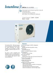
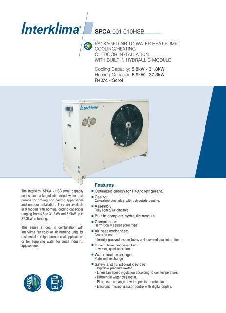
<strong>SPCA</strong> <strong>001</strong>-<strong>010HSB</strong>PACKAGED AIR TO WATER HEAT PUMPCOOLING/HEATINGOUTDOOR INSTALLATIONWITH BUILT IN HYDRAULIC MODULECooling Capacity: 5,8kW - 31,8kWHeating Capacity: 6,9kW - 37,3kWR407c - ScrollThe Interklima <strong>SPCA</strong> - HSB small capacityseries are packaged air cooled water heatpumps for cooling and heating applicationsand outdoor installation. They are availablein 9 models with nominal cooling capacitiesranging from 5,8 to 31,8kW and 6,9kW up to37,3kW in heating.This series is ideal in combination withInterklima fan coils or air handing units forresidential and light commercial applicationsor for supplying water for small industrialapplications.FeaturesOptimized design for R407c refrigerant.Casing:Galvanized steel plate with polyesteric coating.AssemblyFully bolted/welding free.Built in complete hydraulic module.Compressor:Hermetically sealed scroll type.Air heat exchanger:Cross fin coilInternally grooved copper tubes and louvered aluminium fins.Direct drive propeler fan.Low rpm, quiet operationWater heat exchanger.Plate heat exchanger.Safety and functional devices- High/low pressure switch.- Linear fan speed regulation according to coil temperature.- Differential water pressostat.- Plate heat exchanger low temperature protection.- Electronic microprosessor control with digital display.
NOMENCLATURE1 RangeS-small M-mid L-large R-screw-series2 Packaged Chiller Air-cooledPCA3 Model numbers<strong>001</strong>-002-003-004-005-006-007-0104 Cool / Heat ModelR-cooling only H-heat pump5 Compressor typeS-scroll M-tandem scroll R-reciprocatingT-twin screw6 Refrigerant typeA-R22 B-R407c7 Electrical Characteristic-1 Single phase -Ommited Three phase
Contents1. Technical Description2. Specifications3. Capacity Tables4. Available External WaterPressure Curves5. Operation Range6. Sound Data7. Outlook Drawings8. Refrigerant Circuit Diagrams9. Wiring Diagrams10. Installation11. Guide SpecificationsInterklima Hydronic systems<strong>SPCA</strong> <strong>001</strong>-<strong>010HSB</strong> ñ R407c/Scroll 3
1. Technical DescriptionGeneralThe <strong>SPCA</strong>-HSB series air-cooled water heat pump consists of 9models covering cooling capacities from 5,8 up to 31,8kW andheating capacities from 6,9kW up to 37,3kW.It is the end result of a thorough study, and accurate design byexperienced Interklima research and development teams, todevelop a small size heat pump series with compact shape, highperformance, and reliability of the highest quality standards.This series meets the highest levels of aesthetic and technicalrequirements using the latest technological innovations includingenvironmentally friendly R407c refrigerant that is Chlorine-freeand has zero ozone depletion potential. <strong>SPCA</strong>-HSB units aretherefore ideal for installation in urban environments due to theirelegant design, selected materials and low operating sound levels.CasingAll units use metal parts fabricated from heavy gauge galvanizedsteel sheets, formed to ensure maximum rigidity that guaranteesand preserves the units operation during the years. After fabricationmetal parts are degreased, phosphatised, and electrostaticallypowder coated with an epoxy-polyester RAL 9002 coating of athickness of 60-70 Ì. This fully automatic process ensuressuperior corrosion resistance against the most aggressive ambientconditions. The treatment can successfully withstand a salt spraytest of 500 hours, according to ASTM B-117.All components are assembled together using bolts thus avoidingthe need for welding which may harm the galvanization of thesteel, and ensures that the whole assembly can fully withstandadverse weather conditions.The compact footprint of the unit arises from detailed study anddesign by our engineering teams and results in a machine, whichfits easily in restricted areas and is simple and easy to install andmaintain, and has been designed with special fittings for easytransport and lifting.Removable panels with special locks are used to permit accessonly to authorized personnel to internal components of the unit forinspection and maintenance.CompressorAll units use low-noise, maintenance free, Hermetic Scrollcompressor with low vibration levels, specially optimized for usewith R407c refrigerant, selected from world class suppliers.They are equipped with a crankcase electrical heater for the oil,and are internally protected against potential overloading orelectrical spikes.The compressors are mounted on special antivibration rubbermounts to eliminate vibration from the unit’s operation.Hydraulic kitAll units are equipped, as standard, with a complete hydraulic kitcomprising of a circulating pump, buffer and expansion tank,automatic fill and make up water valve with manometer, safetyvalve, airvent, water filter, differential water pressure switch, andevacuation valve.Air heat exchangerAll unit air heat exchangers are manufactured from high qualityinner grooved seamless copper tubes according to ASTM B-280,having an outside diameter of 9,52 mm (3/8"). The fins aremanufactured from aluminium and form the secondary extendedheat transfer surface. The fins are continuous across the heatexchanger and are fabricated in high precision dedicated presslines. The fin surface is waffle formed, so as to increase the finrigidity, and have special louvers that help increase heat transfer.The combination of internally grooved Copper-tubing and louveredfins has resulted in a heat transfer performance 30% superior tothat of a conventional coil for this particular application. Theassembly of the finned pack is achieved by mechanical expansionof the tubes in such a way as to form a perfect mechanical bondwith the fins. For this purpose, the fin holes have a peripheralextrusion (collar) of adjustable height. This extrusion serves todefine the distance between fins (and consequently the total heattransfer surface) and to ensure perfect contact of the fins to thetubes.Alternative fin materials are available upon request such as epoxy- coated aluminium or copper for applications in especiallyaggressive environments.Water heat exchangerAll units are equiped with a water - refrigerant Plate HeatExchanger, selected from world class manufacturers.It is made of stainless steel plates (AISI 3161.4401) speciallyformed to achieved a large heat transfer surface and assembledby means of an automatic brazing proccess, under vaccum.Air heat exchanger fansAll unit fans are of the axial type, single phase, 6 poles, internallyprotected against potential overheating silent and suitable foroutdoor installation. Due to the sophisticated aerodynamic designof the blades and inlet cones, as well as the perfect static anddynamic balancing, their operation is completely vibration-free. Thefan-motor assembly has a protective grid against accidentalcontact with moving parts, which is designed according to ISOregulations. Fan motors are of the external rotor type,aerodynamically shaped so as not to interfere with the airflow, and4Interklima Hydronic systems<strong>SPCA</strong> <strong>001</strong>-<strong>010HSB</strong> ñ R407c/Scroll
have permanently lubricated bearings that do not require servicing.Continuous linear fan speed regulation control is achievedaccording to coil temperatures including fan silent mode operation.This standard feature for Interklima <strong>SPCA</strong> units saves energy andreduces sound levels dramatically, optimizing capacity.Microprocessor controllerAll units are equipped with a sophisticated controller easilyaccessible from outside through a transparent plastic cover thatcombines intelligence with operating simplicity. The controllerconstantly monitors all machine parameters and preciselymanages among othersñ Automatic compressor control function through return watertemperature.ñ Continuous fan speed control based on coil heat exchangertemperature.ñ Defrost control.ñ Hydraulic circuit pump control.ñ Compressor start up time delay function.ñ Over 150 programmable parameters.ñ Fan motor overload protection.ñ Auto diagnostic stop function due to low water circulation,high/low operating pressures, and compressor thermaloverload.ñ Auto diagnostic function and digital display of approximately30 possible error codes including thermistor faults.ñ Digital displays of water inlet / outlet as well as coiltemperatures.ñ Remote Cool / Heat selector switch.ñ Remote on / off switch.ñ Remote alarm indication capability.ñ Many optional control capabilities (listed in optionalaccessories).Optional accessoriesMicroprocessor controller optionsñ Remote keyboard.ñ Dynamic set point program via a 4-20ma proportional signalñ BMS module interface kit for Modbus connection.ñ Parallel chiller operation with more than 2 units with optionalcontroller.ñ Microprocessor parameter reprogramming card.Other unit accessories/optionñ R407c or R22 refrigerant.ñ Antifreeze protection.ñ Condenser fins made of copper or prepainted aluminum, andBlygold treatment for corrosion protection.ñ Glycol application for chilled water temperature down to -5 o Cñ Pressure relief valve on compressor discharge.ñ High / Low pressure manometers.ñ Phase sequence - phase failure - reverse phase and voltagemonitoring device.ñ Compressor noise reduction jacket.ñ Compressor chamber noise reduction kit.ñ Other custom built options upon request.Refrigerant circuitAll units have a single refrigerant circuit with one compressor. Thecircuit consists, depending on the size, of either a capillary orthermal expansion valve. Other components fitted are solenoidvalve, suction accumulator, liquid receiver, check valve, 4way valve,large capacity filter dryer and high/low pressure manometers.Unit protection is provided by a high-pressure switch with manualreset, low-pressure protection is via a low-pressure switch.Interklima Hydronic systems<strong>SPCA</strong> <strong>001</strong>-<strong>010HSB</strong> ñ R407c/Scroll 5
2. Technical specifications2.1 <strong>SPCA</strong> <strong>001</strong>-<strong>010HSB</strong>TypeNominal cooling capacityNominal heating capacityConstructionCompressorQuantityAbsorbed powerNominal operating currentMaximum operating currentAir heat exchangerWater heat exchangerQuantityWater contentMax. Operating pressureConnectionsNominal water flowWater pressure dropMinimum system water contentMaximum unit operating water pressureFanQuantitySpeedTotal air flowAbsorbed powerNominal operating currentMaximum operating currentPumpAbsorbed powerMaximum operating currentAvailable external water headElectrical characteristicsTotal absorbed powerNominal operating currentMaximum operating currentCompressor carter resistance powerPower cables cross sectionFusesVoltage operating limitsRefrigerant circuitNumber of circuitsExpansion deviceRefrigerant typeNoise level at 5mDimensionsShipping weightkWRTBtu/hkWkcalMaterial/ColorkWAAlWater side barRefrigerant side barl/hkpalbarrpmm 3 /hkWAAkWAKpakWAAWmm 2 AVdB(A)Width mmLength mmHeigth mmkg<strong>SPCA</strong>-<strong>001</strong>-1 <strong>SPCA</strong>-002-1 <strong>SPCA</strong>-002 <strong>SPCA</strong>-003 <strong>SPCA</strong>-0045,81.619.7736,95.93412,0/2,39,4/10,614.8010.5730303/4"99826.5293.019202.5000.120.570.630.130.5835.02,3/2,610,6/11,816.07042514547410229321106,92.023.5238,27.05212,4/2,711,1/12,617.3010.6630303/4"1.18727.6353.019202.3500.120.570.630.130.5832.02,7/3,012,2/13,818.57042514547410229321156,92.023.5238,27.052SCROLL12,3/2,74,4/4,85.60Brazed plate10.6630303/4"1.18727.6353.0Axial type19202.3500.120.570.630.130.5832.02,6/3,05,6/6,06.8702.53x161Capillary tubesR407c4647410229321158,12.327.6149,68.256Galvanized steel / Light grey-beige (RAL 9002)12,7/3,15,0/5,57.<strong>001</strong>0.7630301"1.39329.2413.019204.0000.170.800.900.130.5830.03,0/3,46,4/6,98.5702.53x16360-440 V148474122298215512,23.541.59114,312.29814,0/4,57,8/8,311.00High capacity cross finned coil with internally grooved tubes and louver fins230 V/1 ph/50 Hz 400 V/3 ph/50 Hz220-240 V11.1430301"2.09829.9613.029204.6000.241.141.260.251.142.04.5/5.010.0/10.513.4702.53x16148522146210021906Interklima Hydronic systems<strong>SPCA</strong> <strong>001</strong>-<strong>010HSB</strong> ñ R407c/Scroll
TypeNominal cooling capacityNominal heating capacityConstructionCompressorQuantityAbsorbed powerNominal operating currentMaximum operating currentAir heat exchangerWater heat exchangerQuantityWater contentMax. Operating pressureConnectionsNominal water flowWater pressure dropMinimum system water contentMaximum unit operating water pressureFanQuantitySpeedTotal air flowAbsorbed powerNominal operating currentMaximum operating currentPumpAbsorbed powerMaximum operating currentAvailable external water headElectrical characteristicsTotal absorbed powerNominal operating currentMaximum operating currentCompressor carter resistance powerPower cables cross sectionFusesVoltage operating limitsRefrigerant circuitNumber of circuitsExpansion deviceRefrigerant typeNoise level at 5mDimensionsShipping weightkWRTBtu/hkWkcalMaterial/ColorkWAAlWater side barRefrigerant side barl/hkpalbarrpmm 3 /hkWAAkWAKpakWAAWmm 2 AVdB(A)Width mmLength mmHeigth mmkg<strong>SPCA</strong>-005 <strong>SPCA</strong>-006 <strong>SPCA</strong>-007 <strong>SPCA</strong>-01014,64.149.77317,014.62014,6/5,28,3/9,213.<strong>001</strong>1.3530301"2.51134.1733.029206.2000.341.601.800.302.<strong>001</strong>30.05.3/5.811.9/12.816.87043x251Capillary tubes515221612100223018,55.363.06821,718.66216,0/6,812,2/13,117.<strong>001</strong>1.4030301 1/4"3.18234.6933.029206.4000.341.601.800.452.70150.06.8/7.616.3/17.421.57063x251526051732120230022,46.476.36426,222.532Galvanized steel / Light grey-beige (RAL 9002)SCROLL17,2/8,014,5/15,520.<strong>001</strong>1.7030301 1/4"3.85345.41123.0292010.5000.743.403.800.452.70120.08.4/9.220.1/21.626.57063x321Expansion valve/Capillary tubesR407c538002020120235031,89.0108.40937,332.078110,3/11,517,8/19,427.00High capacity cross finned coil with internally grooved tubes and louver finsBrazed plateAxial type400 V/3 ph/50 Hz360-440 V12.5030301 1/4"5.47024.41593.0292011.0000.743.403.800.553.50165.011.3/12.823.9/26.334.370103x4015580020201202380NOTESNominal conditions are asfollowsentering/leaving chilledwater temperature 12/7 o C;ambient 35 o CDB (cooling)entering/leaving heatedwater temperature 40/45 o C;ambient 7 o CDB/6 o CWB(heating)electrical installationspecifications are purelyindicative and non-binding,all connections to thesystem and the electricalinstallation must be in fullaccordance with allapplicable national and localcodes.Interklima Hydronic systems<strong>SPCA</strong> <strong>001</strong>-<strong>010HSB</strong> ñ R407c/Scroll 7
3. Capacity tablesCooling capacity table for <strong>SPCA</strong> <strong>001</strong>-<strong>010HSB</strong>Type<strong>SPCA</strong>-<strong>001</strong>-1<strong>SPCA</strong>-002-1<strong>SPCA</strong>-002<strong>SPCA</strong>-003<strong>SPCA</strong>-004<strong>SPCA</strong>-005<strong>SPCA</strong>-006<strong>SPCA</strong>-007<strong>SPCA</strong>-010Wateroutlet ÆC571057105710571057105710571057105710Coolingcap. kW6.16.77.57.38.08.97.27.98.88.59.210.412.814.015.715.416.718.719.321.023.623.525.428.433.436.140.425 30 35 40 45Absorbedpower kW Current A Coolingcap. kWAbsorbedpower kW Current A Coolingcap. kWAbsorbedpower kW Current A Coolingcap. kWAbsorbedpower kW Current A Coolingcap. kWAbsorbedpower kW1.61.61.61.91.91.81.81.81.82.12.12.13.23.23.23.73.73.74.74.74.75.75.75.78.18.18.27.57.57.48.98.88.73.83.73.74.34.34.36.96.96.96.96.97.010.910.910.913.013.013.015.115.215.25.86.27.06.97.58.46.87.48.38.08.79.812.113.114.814.515.617.518.219.722.222.123.926.831.534.038.11.81.81.82.12.12.12.12.02.02.42.42.43.63.63.64.14.14.15.35.35.36.46.46.49.19.19.18.48.38.29.99.99.84.14.04.04.74.64.67.37.37.37.67.67.611.511.511.513.713.713.616.316.316.4Heating capacity table for <strong>SPCA</strong> <strong>001</strong>-<strong>010HSB</strong>Type<strong>SPCA</strong>-<strong>001</strong>-1<strong>SPCA</strong>-002-1<strong>SPCA</strong>-002<strong>SPCA</strong>-003<strong>SPCA</strong>-004<strong>SPCA</strong>-005<strong>SPCA</strong>-006<strong>SPCA</strong>-007<strong>SPCA</strong>-010Wateroutlet ÆC354045354045354045354045354045354045354045354045354045Heatingcap. kW5.55.45.46.66.5646.46.36.27.57.47.311.110.910.713.513.112.816.916.716.520.820.520.229.829.328.9Ambient temperature o C5.45.86.66.46.97.86.36.97.87.48.19.211.212.213.913.514.616.417.018.520.820.722.425.229.531.835.72.02.02.02.42.42.32.32.32.32.72.72.74.04.04.04.74.74.76.06.05.97.27.27.210.210.310.39.49.49.211.111.110.94.44.44.45.15.05.07.77.87.88.38.38.312.212.212.214.514.514.517.717.817.84.95.46.15.96.47.25.86.47.26.97.58.510.411.312.912.513.615.215.817.219.519.320.923.527.429.633.32.32.32.32.72.72.72.72.62.63.13.13.14.54.54.55.25.25.26.86.86.78.08.08.111.511.511.610.610.610.412.612.512.44.84.84.85.55.55.58.38.38.39.29.29.213.113.113.115.515.515.519.419.419.44.54.95.55.35.86.65.35.86.66.36.87.89.510.411.811.512.514.114.716.018.117.919.421.925.327.430.82.62.62.63.13.13.03.03.03.03.53.53.55.05.05.05.95.95.97.77.77.79.09.09.013.013.013.0-5 0 2 7 10Absorbedpower kW Current A Heatingcap. kWAbsorbedpower kW Current A Heatingcap. kWAbsorbedpower kW Current A Heatingcap. kWAbsorbedpower kW Current A Heatingcap. kWAbsorbedpower kW1.82.12.32.12.42.82.12.42.72.42.83.13.54.04.44.14.65.25.46.06.76.47.28.09.110.211.48.59.610.810.111.312.84.14.44.94.75.15.67.27.78.27.58.39.111.512.213.113.714.515.516.317.619.2NOTESBold values show nominal cooling/heating capacities.5.95.85.77.06.96.86.86.76.68.07.97.811.911.711.414.414.013.718.117.817.622.221.821.431.731.130.61.82.02.32.12.42.82.12.42.72.42.83.13.54.04.44.14.65.25.46.06.86.47.28.09.110.211.48.59.510.810.111.312.84.14.44.94.75.15.67.27.78.27.68.39.111.512.213.113.714.515.516.317.719.3Ambient temperature oC6.26.16.07.47.37.27.37.17.08.58.48.212.812.512.215.315.014.619.318.918.723.623.122.733.633.032.41.82.02.32.12.42.72.12.42.72.42.83.13.64.04.44.14.65.25.36.06.86.47.28.09.110.211.58.59.510.710.011.312.74.14.44.94.75.15.67.27.78.37.68.39.111.512.213.113.714.515.516.317.719.37.37.16.98.78.58.28.68.48.210.09.89.615.114.714.318.017.517.022.622.121.727.526.926.239.238.237.31.82.02.32.12.42.72.12.32.72.42.73.13.64.04.54.14.75.25.36.06.86.47.28.09.110.211.58.49.410.69.911.112.64.14.44.84.75.15.57.37.78.37.68.39.211.512.213.113.714.515.516.317.719.48.07.87.59.59.29.09.49.28.911.010.710.416.716.215.719.719.118.624.924.323.730.229.428.642.941.840.7Absorbed power and current refers to the compressor.Above figures are valid for water ¢t = 5 o C.1.82.02.32.12.42.72.02.32.62.42.73.13.64.04.54.14.75.25.36.06.86.47.28.09.110.311.6Current A12.112.011.914.314.214.15.35.35.36.16.16.08.98.99.010.210.210.214.114.114.116.616.616.621.321.321.4Current A8.39.310.59.811.012.54.04.44.84.65.05.57.37.88.37.68.39.211.512.213.113.714.515.516.417.819.48Interklima Hydronic systems<strong>SPCA</strong> <strong>001</strong>-<strong>010HSB</strong> ñ R407c/Scroll
4. Available external water pressure curves<strong>SPCA</strong> <strong>001</strong>-<strong>010HSB</strong>PD90807060kpa5040004302010<strong>001</strong>0030020 0 500 1.000 1.500 2.000 2.500 3.000 3.500 WFl/hPDkpa3603403203002802602402202<strong>001</strong>80160140120100806040200050 0 500 1,000 1,500 2.000 2.500 3.000 3.500 4.000 4.500 5.000 5.500 6.000 WFl/h006007010NOTESPD: pressure dropWF: water flow rate1. <strong>SPCA</strong> <strong>001</strong>-002HSB2. <strong>SPCA</strong> 003HSB3. <strong>SPCA</strong> 004HSB4. <strong>SPCA</strong> 005HSB5. <strong>SPCA</strong> 006HSB6. <strong>SPCA</strong> 007-<strong>010HSB</strong>ETHYLENE GLYCOL CORRECTION FACTORS% ETHYLENE GLYCOL BY VOLUMEFreezing pointo COutput dutykWInput powerkWEquivalent Flow rateL/HEquivalent Pressure drop kPaUNIT 10-40,990,991,021,0620-90,980,981,041,1230-150,970,981,081,1840-230,960,971,131,25Interklima Hydronic systems<strong>SPCA</strong> <strong>001</strong>-<strong>010HSB</strong> ñ R407c/Scroll 9
5. Operation rangeOOutdoor Temperature ( CDB) COOLING Outdoor Temperature ( CDB)(RH=85%) HEATINGO47452040-50-56 15Leaving waterotemperature( C)25 50Leaving waterotemperature( C)NOTESProtect the water circuit against freezing- The accompanying operating limits are for general guidance only. It may bepossible for certain units to operate outside the confines of the graph. Pleasecontact Interklima if further clarification is required.6. Sound data- For operation with leaving water temperature below 6 o C it is required to confirmwith Interklima at the time of order and the addition of glycol into the system.Type<strong>SPCA</strong> - <strong>001</strong><strong>SPCA</strong> - 002<strong>SPCA</strong> - 003<strong>SPCA</strong> - 004<strong>SPCA</strong> - 005<strong>SPCA</strong> - 006<strong>SPCA</strong> - 007<strong>SPCA</strong> - 010PowerPressure @1 mPressure @10 mPowerPressure @1 mPressure @10 mPowerPressure @1 mPressure @10 mPowerPressure @1 mPressure @10 mPowerPressure @1 mPressure @10 mPowerPressure @1 mPressure @10 mPowerPressure @1 mPressure @10 mPowerPressure @1 mPressure @10 mdB(A)66583967593968604070624271644474664675674777694963494121494121514323524424544626544626544626544626Octave band center frequency (Hz)125554727554727564828585030595131595131605232605232250564828564828574929595131605232615333605232615333500585030585030595131615333615333696141696141706242100062543462563664563665573767593968604068604069614120005951316155356254346355356456366759397062427365454000544626585333585030585030655737635535655737706242800049412148422249412150422253452550422250422257492910Interklima Hydronic systems<strong>SPCA</strong> <strong>001</strong>-<strong>010HSB</strong> ñ R407c/Scroll
7. Outlook drawings7.1 <strong>SPCA</strong> <strong>001</strong>-002HSB474460102210089324504910007.2 <strong>SPCA</strong> 003HSB4744601222120898145051 12007.3 <strong>SPCA</strong> 004HSB5221462508 14481002500 14407.4 <strong>SPCA</strong> 005HSB522 1612508 15981002500 1590Interklima Hydronic systems<strong>SPCA</strong> <strong>001</strong>-<strong>010HSB</strong> ñ R407c/Scroll 11
7.5 <strong>SPCA</strong> 006HSB175417405012026054017327.6 <strong>SPCA</strong> 007-<strong>010HSB</strong>13720422028120280040 202012Interklima Hydronic systems<strong>SPCA</strong> <strong>001</strong>-<strong>010HSB</strong> ñ R407c/Scroll
8. Refrigerant circuit diagrams8.1 <strong>SPCA</strong> <strong>001</strong>-005HSB386678152948.2 <strong>SPCA</strong> 006-<strong>010HSB</strong>3 8 831526NOTES1. Scroll compressor2. Plate heat exchanger3. Air heat exchanger4. Suction accumulator5. 4-way reversing valve6. Check valve7. Filter dryer8. Capillary9. Liquid receiver10. Thermal expansion valve11. Solenoid valve12. Liquid glass946 7121110Interklima Hydronic systems<strong>SPCA</strong> <strong>001</strong>-<strong>010HSB</strong> ñ R407c/Scroll 13
9. Wiring diagrams9.1 <strong>SPCA</strong> <strong>001</strong>-002HSB-1SM1ALARM OUTPUTgrd grd grdLNPEALAL12AC ALL12AC 12DCGNDTK1GNDID5ST4ID4S3ST3ID3S2ST2ID2S1ST1ID1F 2ASONFLHENERGY 210CCCC12V12VTRWOffS P P220VCMCCHNEMIFILTERCf1 CC1FM1CCCPM4A4VFPV9.2 <strong>SPCA</strong> 002-003HSBSM1ALARM OUTPUTgrd grd grdL1L2L3NPEVCALF 2AAL12AC ALL12AC 12DCENERGY 210GNDTK1GNDID5SST4ID4ONS3ST3ID3FS2ST2ID2LS1ST1ID1HCCCC12V12VTRWOffS P P220VCMCHNVCEMIFILTERCf1 CC1FM1CCCPM4A4VFPV9.3 <strong>SPCA</strong> 004-005HSBSM1ALARM OUTPUTgrd grd grdL1L2L3NPEVCALF 2AAL12AC ALL GND GND12AC 12DC TK1 ID5ENERGY 210SST4ID4ONS3 S2 S1ST3ID3FST2ID2LST1ID1HCCCPCC12V12VTRWOffS P P220VCMPMCHNVCEMIFILTERCf2 C Cf1 CC2 C1FM2 FM1CCCCP4A4VFPV14Interklima Hydronic systems<strong>SPCA</strong> <strong>001</strong>-<strong>010HSB</strong> ñ R407c/Scroll
9.4 <strong>SPCA</strong> 006HSBSM1ALARM OUTPUTTgrd grd grdL1L2L3NPEVCALF 2AAL12AC ALL12AC 12DCENERGY 210GNDTK1GNDID5SCST4ID4ONS3ST3ID3FS2ST2ID2LS1ST1ID1HCCCPCC12V12VTRWOffS P P220VCMPMCHNVCEMIFILTERCCSVCf2 CC2FM2Cf1 CC1FM1FCCCPCP4VA4V9.5 <strong>SPCA</strong> 007-<strong>010HSB</strong>SM1ALARM OUTPUTTgrd grd grdL1L2L3NPECCVCCPCC12VALF 2A12VTR220VCF 22 3334FAN SPEEDCONTROLLER24 F1AL12AC ALL12AC 12DCENERGY 210GNDTK1GNDID5SWCST4ID4ONOffS3ST3ID3FS2ST2ID2LS1ST1ID1HS P PCMPMCHNVCEMIFILTERCCSVCf2 CC2FM2Cf1 CC1FM1FCCCPCP4VA4VLEGENDSM1 GENERAL CIRCUIT BREAKERCC COMPRESSOR CONTACTORCH COMPRESSOR CRANKCASE HEATERTR TRANSFORMER 220/2x12VACHP HIGH PRESSURE PRESSOSTATLP LOW PRESSURE PRESSOSTATF CONTROL CIRCUIT BREAKER (2A)C1,2 COND, FANS 1, 2 CAPACITORSFS WATER DIFFERENTIAL PRESSOSTATTC COMPRESSOR THERMAL PROTECTION4V 4-WAY VALVES1 ENTERING WATER SENSORS2 LEAVING WATER SENSORS3 CONDENSER COIL TEMPERATURE SENSORA COMMAND 220VAC FOR ELECTRICAL HEATERS(OPTIONAL)CP PUMP CONTACTORPM PUMPCM COMPRESSORVC VOLTAGE SURVEYOR (OPTIONAL)SV LIQUID SOLENOID VALVEALARME00:E01:E02:E03:E05:E06:E07:E41:REMOTE ON/OFF IN POSITION OFFHIGH PRESSURELOW PRESSURECOMPRESSOR THERMAL PROTECTION*(*ONLY FOR <strong>SPCA</strong> 006-010∏SB)ANTIFREEZEPROBE ST2 FAULTPROBE ST3 FAULTWATER DIFFERENTIAL PRESSOSTATFIELD CONNECTIONSONOFFS W AL ALON -OFF REMOTE SWITCH (DRY CONTACT)AL-AL ALARM 12 V ACS-W REMOTE SUMMER-WINTERSWITCH (DRY CONTACT)Interklima Hydronic systems<strong>SPCA</strong> <strong>001</strong>-<strong>010HSB</strong> ñ R407c/Scroll 15
10.Installation10.1 Selection of location - service spaceThe <strong>SPCA</strong>-HSB unit should be installed in a location that meets thefollowing requirements:1. The foundation is strong enough to support the weight of the unit,and the floor is flat to prevent vibration and noise generation.2. The space around the unit is adequate for servicing and theminimum space air inlet and air outlet is available. If several unitsare being installed side by side in parallel, the minimum servicespace between them must be taken into account3. There is no danger of fire due to leakage of inflammable gas.4. Ensure that water cannot cause any damage to the location incase it drips out the unit.5. Make sure that the air inlet and outlet of the unit are notpositioned towards the main wind direction.Frontal wind willdisturb the operation of the unit.If necessary, use a windscreento block the wind.6. In heavy snowfall areas, select an installation site where snowwill not affect operation of the unit.7. Make sure that the unit mounting base can be fixed directly onconcrete.8. In order to avoid the transmission of vibration from the operatingunit to its carrying structure, the use of antivibration material toinstall under the supports of the unit is recommended. It issuggested to install a rubber pad between the points of supportand the base of the unit, or spring antivibration mounts undereach point of support of the unit.400mm500mm500mm(1500mm for006-010 models)800mm500mm10.2 Centre of gravity<strong>SPCA</strong> <strong>001</strong>-002HSB<strong>SPCA</strong> 003HSB420420175390175490<strong>SPCA</strong> 004HSB<strong>SPCA</strong> 005HSB420420200570200 62016Interklima Hydronic systems<strong>SPCA</strong> <strong>001</strong>-<strong>010HSB</strong> ñ R407c/Scroll
<strong>SPCA</strong> 006HSB<strong>SPCA</strong> 007-<strong>010HSB</strong>590590250650350 75010.3 Recomendations concerning the hydraulic circuitñ All units are equipped with a complete hydraulic kit as shownthe figure belowñ All field conections must be carried out by a licensed technicianand must comply with the applicable local and national codesñ Evaporator water connections should be made in accordancewith the unit outlook respecting the water inlet – and outletsñ Connect a fresh water line to the water make up connection.The units are equipped with automatic make up valve tofacilitate water make up.ñ It is advisable to connect flexible water inlet and outlet tubesto avoid vibration transmissionñ The unit is operating in closed circuit. Avoid frequentunessasary water evacuation.ñ It is essential to install a thermometer in the water inlet/ outletpipe to check temperatures.ñ Provide heat insulation with suitable vapour barrier around thechilled water piping to prevent condensation and capacity loss.ñ Provide drain connections at all low points of the system topermit complete drainage for maintenance and/ or shutdownñ Air vents should be provided at all high points in the systemlocated where they are easily accessible for servicing. Thewater inlet pipe is specially designed to obtain a complete airpurge of the evaporator.ñ To avoid frequent on / off operation of the compressor, aminimum water volume is required in the system (table 10.4)ñ To assure proper operation of the unit, the water qualitythrough the evaporator must be within the specified limits(table10.4).NOTES1. Pump2. Plate heat exchanger3. Automatic make up watervalve with manometer4. Buffer tank (water accumulation)5. Expansion tank6. Airvent7. Pressure relief valve8. Differential water pressure switch9. Water filterInterklima Hydronic systems<strong>SPCA</strong> <strong>001</strong>-<strong>010HSB</strong> ñ R407c/Scroll 17
10.4 Watercharge, flow and qualityTo ensure proper operation of the unit, a minimum water volumeis required in the system and the water flow must be within theoperation range as specified in the table.<strong>SPCA</strong>-<strong>001</strong>-1HSB<strong>SPCA</strong>-002-1HSB<strong>SPCA</strong>-002HSB<strong>SPCA</strong>-003HSB<strong>SPCA</strong>-004HSB<strong>SPCA</strong>-005HSB<strong>SPCA</strong>-006HSB<strong>SPCA</strong>-007HSB<strong>SPCA</strong>-<strong>010HSB</strong>Minim umwatervolume (l)29353541617393112159Minim umwater flow(l/h)94811271127132419932386302336605196Nominalwater flow(l/h)99811871187139320982511318238535470Maxim umwater flow(l/h)109713051305153323082762350042386017Be sure the water quality is in accordance with the specificationsbelowNOTESThe above tables are purelyindicative and non-bindingItemsItems to be controlled:PH AT 25 Ô C∂lectrical conduct (mS/m) at 25 Ô CChloride ion (mg CI-/I)Sulfate ion (mg SO 2/4/IM-alkalinity (ph 4.8) (mg SO3/I)Total hardness (mg CaCO3/I )Calcium hardness (mg CaCO3/I)Silica ion (mg SiO2/IItems to be referred to:Iron (mg Fe/I)Copper (mg Cu/I)Sulfide ion (mg S2-/I)Amonium ion (mg NH+4/IRemaining chloride (mg CI/I)Free carbide (mg SO2/I)Stability indexCirculatingwater 20CEvaporator water6.8 - 8.0below 30below 50below 50below 50below 70below 50below 30below 1.0below 1.0Not detectablebelow 0.3below 0.25below 0.4-Supply water6.8 - 8.0below 30below 200below 50below 50below 70below 50below 30below 0.3below 0.1Not detectablebelow 0.1below 0.3below 4.0-Circulatingwater 20C-60C7.0 - 8.0below 30below 30below 30below 50below 70below 50below 30Heated waterbelow 1.0below 1.0Not detectablebelow 0.1below 0.1below 0.4-Supply water7.0 - 8.0below 30below 30below 30below 50below 70below 50below 30below 0.3below 1.0Not detectablebelow 0.1below 0.3below 4.0-Tendencyif out of criteriacorrosion + scalecorrosion + scalecorrosioncorrosionscalescalescalescalecorrosion + scalecorrosioncorrosioncorrosioncorrosioncorrosioncorrosion + scale10.5 Operating pressure of therefrigerant circuit.It is important to check the high and low pressure of therefrigerant circuit to ensure the proper operation of the unitand to guarantee that the rated output will be obtained.Cooling mode(region)low pressurehigh pressureMinim um(outdoor temp. 15 Ô NominalCDB)(leaving water temp 6 Ô (outdoor temp. 35 Ô MaximumCDB)C) (leaving water temp, 7 Ô (outdoor temp. 38 Ô CDB)C) (leaving water temp, 25 Ô C)3,5-4 bar17-19 bar4-5 bar21-23 bar5,5-6 bar24-26 barAttention:The pressures measured will vary between a maximum andminimum value, depending on the water and ambienttemperatures at the moment of measurement.Heating mode(region)low pressurehigh pressureMinim um(outdoor temp. -5 Ô CDB)Nominal(outdoor temp. 7 Ô CDB)Maximum(outdoor temp. 21 Ô CDB)(leaving water temp 25 Ô C) (leaving water temp, 45 Ô C) (leaving water temp, 50 Ô C)2.5-3 bar15-18 bar3-3.5 bar21-23 bar3,5-5 bar25-26 bar18Interklima Hydronic systems<strong>SPCA</strong> <strong>001</strong>-<strong>010HSB</strong> ñ R407c/Scroll
10.6 Digital controlerUser interface <strong>SPCA</strong> <strong>001</strong>-<strong>010HSB</strong>The interface on the front panel can be used to carry out all theoperations connected to the use of the instrument, and inparticular to:Set operating modeCheck the state of resourcesRespond to alarm situations10.6.1 Keys1 2Front panel of the instrumentSelects operating mode:If the heating mode is enabled, each time thekey is pressed the following sequence occurs:Stand-by cooling heating stand byIf cooling mode is enabled:heating Stand-by cooling heating stand byIn menu mode, this key acts as a SCROLL UPor UP key (increasing value).Resets alarms, and turns the instrument onand off. Press once to reset all manually resetalarms not currently active.Hold down the key for 2 seconds to turn theinstrument from on to off or vice versa. When it isoff, only the decimal point remains on the display.In menu mode this key acts as a SCROLL DOWNor DOWN key (decreasing value).Pressing the “mode” and “on-off” keys at thesame time.If you press both keys at the same time andthen release within 2 seconds, you will moveone level deeper in the display menu.If you press both keys for more than 2 secondsyou will move one level up.If you are currently viewing the lowest level inthe menu and you press both keys and releasewithin 2 seconds, you will go up one level.10.6.2 Displays10.6.2.1 DisplayNormal display shows:ñ Regulation temperature in tenths of degreescelsius with a decimal point, or in degreesfahrenheit without a decimal point.ñ The alarm code, if at least one alarm is active. Ifmultiple alarms are active, the one with greaterpriority will be displayed, according to the Tableof Alarms.ñ If temperature control is not analogue anddepends on the status of a digital input (ST1 orST2 configured as digital inputs), the “On” or“Off” label will be displayed, depending onwhether temperature control is active or not.ñ When in menu mode, the display depends on thecurrent position; labels and codes are used tohelp the user identify the current function.ñ Decimal point: when displaying hours of operation,indicates that the value must be multiplied x 100.10.6.2.2 LedLed 1 compressor 1(step 1)ON if compressor 1 is activeOFF if compressor 1 is offRapid BLINK if safety timing is in progressSlow BLINK if compressor is currently set to defrost (heatpump version)Power step 2 ledNot usedDefrost led (heat pump version)ON if defrosting is in progressOFF if defrosting is disabled or has been completedBLINK if timing is in progress (defrost interval)Electrical heater/boiler ledON if the internal anti-freeze electrical heater or boiler is onOFF if the internal anti-freeze electrical heater or boiler is offHeating led (heat pump version)ON if the device is in heating modeCooling ledON if the controller is in cooling modeIf neither the HEATING led nor the COOLING led is on, thecontroller is in STAND-BY modeInterklima Hydronic systems<strong>SPCA</strong> <strong>001</strong>-<strong>010HSB</strong> ñ R407c/Scroll 19
10.7 Remote keyboardThe remote keyboard on the display is an exact copy of theinformation displayed on the instrument, with the same leds;Connection with the controller is illustrated below:ConnectionRemote keyboard252426BlueRedBlackBack sideIt performs exactly the same functions as those described in thedisplay section.The only difference is in use of the UP and DOWNkeys (to increase and decrease value), which are separate fromthe MODE and ON/OFF keys.Conn. AConn. B20Interklima Hydronic systems<strong>SPCA</strong> <strong>001</strong>-<strong>010HSB</strong> ñ R407c/Scroll
11.Guide specifications<strong>SPCA</strong> <strong>001</strong>-<strong>010HSB</strong>The supply, transport to jobsite, installation, commissioning andstart up of an air cooled water heat pump with the followingtechnical characteristics.The unit shall be factory assembled, charged with R407crefrigerant and factory tested.The capacity of the unit shall be no less than:Cooling capacity:In the following conditionsAmbient air temperature (DB)Entering water temperatureLeaving water temperaturekWÆCÆCÆCHeating capacity:kWIn the following conditionsAmbient air temperature (DB) ÆCAmbient relative humidity %Entering water temperature ÆCLeaving water temperature ÆCThe unit shall operate unhindered within 6 to 15ÆC/25 o C to 50 o C(cool/heat) water outlet temperature, 3.5 to 7ÆC watertemperature difference and 5 up to 45ÆC ambient air temperature.The structural requirements shall be the following:UNIT HOUSINGThe unit housing shall be fabricated from heavy gauge galvanizedsteel sheets, formed to ensure maximum rigidity that shall guaranteeand preserve the unit operation during the years. All metal parts afterfabrication shall be degreased phosphatized, and electrostaticallypowder coated with epoxy- polyester RAL 9002 coating of athickness of 60-70 m. The corrosion resistance treatment mustsuccessfully withstand a salt spray test of 500 hours, according toASTM B- 117. All components shall be assembled exclusivelytogether using bolts, without welding. The unit shall have removableaccess panels, designed in such a manner as to permit easy accessto internal compartments only by authorized personnel.COMPRESSORShall be of the hermetic scroll type, with low noise and vibrationlevels, specially optimized for use with R407c refrigerant. It shallbe equipped with a crank case electrical heater, to separaterefrigerant and oil when the unit is not operating. It shall alsoinclude internal protection against overloading or electrical spikes.The compressor shall be mounted on special ant vibration rubbermounts to absorb and eliminate any vibration that can begenerated from the unit base.HYDRAULIC KITThe unit shall be equipped with a complete hydraulic kit,comprising of a circulating pump, buffer and expansion tank,automatic fill / make up water valve with manometer, safety valve,air vent, water filter and differential water pressure switch.AIR HEAT EXCHANGERThe air hear exchanger shall be manufactured from seamlesscopper tubes having an outside diameter of 9.52mm (3/8'') of highquality according to ASTM B 280. The tubes shall be internallygrooved to achieve optimized heat transfer between refrigerant andtube. The fins shall be manufactured from aluminium. The fins shallbe continuous across the heat exchanger and the fin surface shallbe waffle formed and louvered so as to increase the fin rigidity andheat transfer. The combination of internally grooved copper tubingand louvered fins must result in a heat transfer performance 30%superior to that of a conventional coil.The assembly of the finned pack shall be achieved by mechanicalexpansion in such a way as to form a perfect mechanical bondwith the fins. For this purpose, the fin holes shall have a peripheralextrusion (collar).WATER HEAT EXCHANGERThe water heat exchanger shall be of the plate heat exchangertype, selected from world-class manufacturers and made ofstainless steel plates (AISI 3161.4401) specially formed toachieve optimized heat transfer. The plates shall be assembled bymeans of an automatic brazing process, under vaccum.AIR HEAT EXCHANGER FANSThe unit shall be equipped with axial type fans, single phase, and6 poles, internally protected against potential overheating,noiseless and suitable for outdoor installation. The design of theblades and inlet cones shall be aerodynamic, and the fan motorassembly shall be perfectly statically and dynamically balancedallowing a completely vibration free operation. The fan motorassembly shall have a protective grid against accidental contactwith moving parts according to ISO. The fan motor shall be of theexternal rotor type with permanently lubricated bearings that donot require servicing. The motor shall be aerodynamically shapedso as not to interfere with the airflow. The unit shall be equippedwith a continuous linear fan speed regulation control according tocoil temperature.Interklima Hydronic systems<strong>SPCA</strong> <strong>001</strong>-<strong>010HSB</strong> ñ R407c/Scroll 21
CONTROL SYSTEM WITH MICROPROCESSOR CONTROLLERThe control system shall possess a sophisticated controller thatshall constantly monitor all machine parameters and particularlymanage among others:ñ Automatic compressor control function through return watertemperature.ñ Continuous fan speed control based on coil heat exchangertemperature.ñ Defrost control.ñ Hydraulic circuit pump control.ñ Compressor start up time delay function.ñ Compressor running time records.ñ Over 150 programmable parameters.ñ Fan motors overload protection.ñ Auto diagnostic stop function due to low water circulation,high / low operating pressures and compressor thermaloverload.ñ Auto diagnostic function and digital display of approximately30 possible error codes including thermistor faults.ñ Digital displays of inlet/ outlet as well as condensingtemperatures.ñ Remote cool/ heat and on / off selectionñ Various other optional control capabilities (listed in options)NOTEThe consultant may if required add the below mentioned optionalaccessories / functions.ñ Remote keyboard.ñ Dynamic set point program via a 4 20 mA proportionalsignal.ñ BMS module interface kit for modbus connection.ñ Parallel chiller operation with more than 2 units with optionalcontroller.ñ Microprocessor parameters reprogramming card.ñ Condenser fins made of prepainted aluminum or copper, andblygold treatment for additional corrosion protection.ñ Plate exchanger-freezing protection for low chilled watertemperature controlled by microprocessor.ñ Glycol for low chilled water temperatures.ñ Pressure relief valve on compressor dischargeñ High / low pressure manometers.ñ Phase sequence phase failure - reverse phase and voltagemonitoring device.REFRIGERANT CIRCUITThe unit shall have a single refrigerant circuit with onecompressor. The circuit shall consist of a filter dryer, expansiondevice, solenoid valve, check valve, liquid receiver, suctionaccumulator, 4way valve and a high and low pressure switch withmanual reset.22Interklima Hydronic systems<strong>SPCA</strong> <strong>001</strong>-<strong>010HSB</strong> ñ R407c/Scroll
Engineering Data 2006Products are manufactured in ISO 9<strong>001</strong>:2000certified factories. ISO 9<strong>001</strong>:2000 pertains to qualityassurance regarding design, development,manufacturing and installation of productsas well as to services related to the product.Interklima units comply with the European regulations thatguarantee the safety of the productSpecifications subject to change without noticeINTERKLIMA PRODUCTS ARE DISTRIBUTED BY:EGB-B-3-2-05/06