You also want an ePaper? Increase the reach of your titles
YUMPU automatically turns print PDFs into web optimized ePapers that Google loves.
<strong>ZX</strong><br />
<strong>Flathead</strong> <strong>VI</strong><br />
<strong>DS</strong>-<strong>IV</strong><br />
<strong>50D</strong><br />
Regulator Service Manual<br />
For Zeagle Scuba Regulator Models: <strong>50D</strong>, <strong>DS</strong>-<strong>IV</strong>, <strong>Flathead</strong> <strong>VI</strong> 1st<br />
Stages and <strong>ZX</strong> 2nd Stage, <strong>ZX</strong> Octo
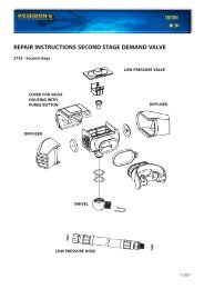
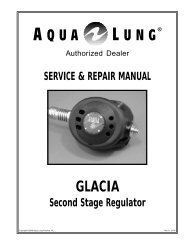
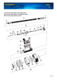
<strong>Flathead</strong>-<strong>VI</strong> 1st Stage Parts<br />
ITEM # PART # DESCRIPTION......<br />
1 341-0149-CL Environmental End Cap<br />
2* 341-0121-MC Hydrostatic Diaphragm (clear)<br />
3 341-0148-AA Label (for <strong>Flathead</strong>-<strong>VI</strong>)<br />
4 341-0119-KA Hydro-Transmitter<br />
5 341-0103-CD Spring Adjuster<br />
6 341-0122-CD Diaphragm Clamp<br />
7 341-0140-VH Regulating Spring<br />
8 341-0104-CD Spring Carrier<br />
9* 341-0105-TA Internal Diaphragm (black)<br />
10 341-0106-VH Lifter<br />
11 341-0109-CD Seat Support<br />
12* 341-0108-JA Seat (orifice)<br />
13* 160-0009-N9 O-ring (for seat)<br />
15* 160-0011-N7 O-ring (for LP port plugs)<br />
16 341-0127-CD LP Port Plug (includes O-ring)<br />
17 341-0128-CD HP Port Plug (includes O-ring)<br />
18* 160-0012-N9 O-ring (for HP port plugs)<br />
19 341-0129-AA DIN Cap<br />
20* 160-0111-N7 O-ring (for inlet of DIN bolt)<br />
21 341-0112-CD Din Connector Bolt<br />
22* 341-0139-BA Conical Filter<br />
23* 160-0011-N7 O-ring (for filter & bolt)<br />
24 341-0142-AA DIN Wheel<br />
25 341-0115-AA Yoke Knob Assembly<br />
26 341-0117-LA Dust Cap<br />
27 341-0111-CD Yoke Bolt<br />
28 341-0113-DL Yoke, Satin Finish<br />
29 341-0146-SA Saddle Spacer<br />
30 341-0107-VH HP (high pressure) Valve<br />
31 341-0141-VA Valve Spring<br />
32* 160-0006-N7 O-ring (smallest O-ring in HP balance plug)<br />
33* 160-0905-N9 O-ring (middle sized O-ring on HP balance plug)<br />
34* 160-0016-N7 O-ring (largest sized O-ring on HP balance plug)<br />
35 341-0151-CL HP Balance Plug<br />
42 341-0145-CL Body, Satin Finish (for <strong>Flathead</strong>-<strong>VI</strong> 1st stage)<br />
43 341-0147-AA Label<br />
44 341-0150-SA Trim Ring<br />
45 341-0152-SK Washer (for DIN Wheel)<br />
19<br />
* An asterisk next to the Item Number<br />
means that part is included in the Standard<br />
Service Kit. The Service Kit Part # for the<br />
1st Stage is 345-1000. The 2nd Stage<br />
Service Kit Part # is 345-2000.<br />
25<br />
26<br />
20<br />
27<br />
21<br />
<strong>Flathead</strong> <strong>VI</strong> First Stage<br />
Assembly<br />
Yoke Model: 310-4110<br />
DIN Model: 310-4120<br />
1<br />
2<br />
3<br />
4<br />
5<br />
44<br />
6<br />
24<br />
7<br />
8<br />
22<br />
23<br />
13<br />
12<br />
11<br />
9<br />
10<br />
42<br />
15<br />
28<br />
29<br />
30<br />
16<br />
31<br />
18<br />
17<br />
33<br />
35<br />
34<br />
32<br />
43
25<br />
19<br />
20<br />
26<br />
21<br />
27<br />
22<br />
24 23<br />
28<br />
37<br />
38<br />
39<br />
31<br />
33<br />
41<br />
1<br />
2<br />
3<br />
4<br />
5<br />
7<br />
6<br />
8<br />
9<br />
10<br />
11<br />
12<br />
29<br />
13<br />
36<br />
18<br />
17<br />
15<br />
16<br />
30<br />
32<br />
40<br />
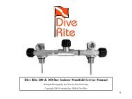
Go to next page for Item Numbers.<br />
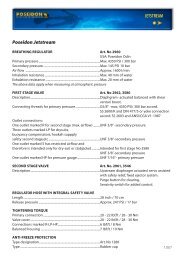
<strong>50D</strong> First Stage Assembly<br />
Yoke Model: 310-2110<br />
DIN Model: 310-2120
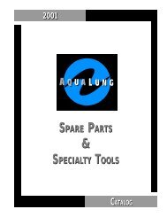
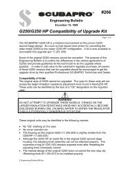
ITEM # PART # DESCRIPTION......<br />
1 341-0118-SA Environmental End Cap<br />
2* 341-0121-MC Hydrostatic Diaphragm (clear)<br />
3 341-0144-AA Label (specify model to customer service)<br />
4 341-0119-KA Hydro-Transmitter<br />
5 341-0103-CD Spring Adjuster<br />
6 341-0122-CD Diaphragm Clamp<br />
7 341-0140-VH Regulating Spring<br />
8 341-0104-CD Spring Carrier<br />
9* 341-0105-TA Internal Diaphragm (black)<br />
10 341-0106-VH Lifter<br />
11 341-0109-CD Seat Support<br />
12* 341-0108-JA Seat (orifice)<br />
13* 160-0009-N9 O-ring (for seat)<br />
14 341-0101-CL Body, Satin Finish (for <strong>DS</strong>-<strong>IV</strong>, non-swivel style 1st stage)<br />
15* 160-0011-N7 O-ring (for LP port plugs)<br />
16 341-0127-CD LP Port Plug (includes O-ring)<br />
17 341-0128-CD HP Port Plug (includes O-ring)<br />
18* 160-0012-N9 O-ring (for HP port plugs)<br />
19 341-0129-AA DIN Cap<br />
20* 160-0111-N7 O-ring (for inlet of DIN bolt)<br />
21 341-0112-CD Din Connector Bolt<br />
22* 341-0139-BA Conical Filter<br />
23* 160-0011-N7 O-ring (for filter & bolt)<br />
24 341-0142-AA DIN Wheel<br />
25 341-0115-AA Yoke Knob Assembly<br />
26 341-0117-LA Dust Cap<br />
27 341-0111-CD Yoke Bolt<br />
28 341-0113-DL Yoke, Satin Finish<br />
29 341-0116-KA Spacer<br />
30 341-0107-VH HP (high pressure) Valve<br />
31 341-0141-VA Valve Spring<br />
32* 160-0006-N7 O-ring (smallest O-ring in HP balance plug)<br />
33* 160-0905-N9 O-ring (middle sized O-ring on HP balance plug)<br />
34* 160-0016-N7 O-ring (largest sized O-ring on HP balance plug)<br />
35 341-0110-CD HP Balance Plug<br />
36 341-0123-CL Body, Satin Finish (for <strong>50D</strong>, swivel style 1st stage)<br />
37* 160-0024-N7 O-ring (for <strong>50D</strong> body to turret)<br />
38 341-0124-CL Turret, Satin Finish<br />
39 341-0125-GA Thrust Washer<br />
40 160-0019-N7 O-ring (for turret to turret bolt)<br />
41 341-0120-CD Turret Bolt<br />
* An asterisk next to the Item Number means that part is<br />
included in the Standard Service Kit. The Service Kit Part<br />
# for the 1st Stage is 345-1000. The 2nd Stage Service Kit<br />
Part # is 345-2000.<br />
IMPORTANT: Items 14, 28, 36, and 38 had a shiny<br />
chrome finish in early models rather than the current satin<br />
chrome finish. If you want to order these parts in a shiny<br />
chrome finish instead of satin, change the last letter in the<br />
part number from “L” to ”D”.These parts in a shiny chrome<br />
finish will be subject to availability.<br />
25<br />
19<br />
26<br />
20<br />
21<br />
27<br />
22<br />
28<br />
24 23<br />
30<br />
29<br />
31<br />
33<br />
35<br />
1<br />
2<br />
3<br />
4<br />
5<br />
6<br />
7<br />
8<br />
9<br />
12<br />
10<br />
13<br />
11<br />
14<br />
15<br />
16<br />
18<br />
17<br />
32<br />
34<br />
<strong>DS</strong>-<strong>IV</strong> First Stage Assembly<br />
Yoke Model: 310-4110<br />
DIN Model: 310-4120
TABLE OF CONTENTS<br />
1.0 Introduction<br />
2.0 Specifications<br />
2.1 Torque Specifications<br />
2.2 Model Numbers<br />
3.0 O-rings Reference Chart<br />
4.0 First Stage Procedures<br />
4.1 Tools Required for First Stage Servicing<br />
4.2 Disassembly of the First Stage<br />
4.3 Cleaning and Inspection of the First Stage<br />
4.4 Preliminary Assembly of the First Stage<br />
4.5 Set-up and Testing of the First Stage<br />
4.6 Final Assembly of the First Stage<br />
5.0 <strong>ZX</strong> Second Stage Service Procedures<br />
5.1 Tools Required for Second Stage Servicing<br />
5.2 Disassembly of the Second Stage<br />
5.3 Cleaning and Inspection of the Second Stage<br />
5.4 Preliminary Assembly of the Second Stage<br />
5.5 Set-up of the Second Stage<br />
5.6 Final Assembly of the Second Stage<br />
5.7 Testing of the Second Stage<br />
6.0 Helpful Hints<br />
6.1 Troubleshooting<br />
6.2 Parts Cleaning Recommendations<br />
6.3 Commonly Used Cleaning Solutions<br />
6.4 Handling Tips<br />
7.0 Warranty and Maintenance Information<br />
7.1 Proper Procedure for Warranty Paperwork<br />
7.2 Scheduled Maintenance<br />
7.3 Order Form (sample)<br />
Before You Begin ...........<br />
Read these instructions completely before you begin servicing the regulator. These instructions are<br />
intended for people who have been AUTHORIZED by Zeagle to repair Zeagle Scuba equipment. If you<br />
are not so authorized - STOP.<br />
FIRST STAGE<br />
The letter at the beginning of the serial number on the first stage indicates the model of that first stage.<br />
If the serial number begins with “A” it is a <strong>DS</strong>-<strong>IV</strong> non-swivel first stage (e.g.A001324). If the serial number<br />
begins with “B” it is a <strong>50D</strong> swivel turret first stage. If the serial number begins with “F” it is a <strong>Flathead</strong><br />
<strong>VI</strong> first stage. For further information, contact Zeagle.
1.0 INTRODUCTION<br />
1.1 The procedures in this manual apply to Zeagle Scuba Regulators.There are two front cover fold outs<br />
inside containing exploded views of the first stages.The one you fold out depends on which model you<br />
are sevicing. One foldout is for the <strong>Flathead</strong>-<strong>VI</strong> first stage.The other is for the <strong>50D</strong> (swivel) and <strong>DS</strong>-<strong>IV</strong><br />
(non-swivel) model. If you are not sure which first stage you are working on, refer to the pictures on<br />
the front of this manual. Refer to the exploded view as you read the service section of the manual. The<br />
Item Numbers referred to in the service section are those seen in the exploded view.<br />
WARNING<br />
NEVER reuse the diaphragm in the first stage.A used diaphragm will not clamp securely as required.A<br />
used diaphragm may come loose during use, causing a severe regulator malfunction.This is true with all<br />
diaphragm first stages. Failure to read this warning may result in serious injury or death.<br />
NEVER tighten the hose fitting to the first stage with more than 40 in. lbs. (4.5 Nm) of torque.The inlet<br />
hose fitting will be weakened by over tightening. Failure to read this warning may result in serious injury<br />
or death.<br />
NOTE: All Zeagle Scuba Regulators have service kits available which contain the parts which must be<br />
changed at every annual service no matter what their condition. The standard annual service kit part<br />
numbers are shown in the parts list. All other parts not contained in these kits must be inspected by<br />
the technician and changed under warranty only if they have failed due to problems with material or<br />
workmanship.<br />
WARNING<br />
Zeagle Scuba Regulators are manufactured using materials suitable for use with oxygen enriched gases<br />
(i.e. Nitrox, etc.) providing the oxygen content does not exceed 40%. Equipment intended for enriched<br />
air (Nitrox) use must not be used with regular compressed breathing air, or other gases. Regulators<br />
intended for enriched air use can be serviced only by technicians trained by one of the major oxygen<br />
enriched air training agencies. Failure to heed this warning may result in serious injury or death.<br />
1.2 This manual gives breakdowns of regulator parts, equipment specifications, servicing instructions,<br />
troubleshooting recommendations, and guidelines for proper care of Zeagle regulators. This manual is<br />
intended for use only by persons specially trained and authorized to service Zeagle Scuba equipment.<br />
1.3 Anyone attempting to service or repair Zeagle Scuba regulators must have a thorough understanding<br />
of the principles of operation of scuba regulators and valves, as well as the appropriate mechanical<br />
ability. The technician must be properly trained in the safe use of compressed air and the various<br />
tools and cleaning solutions involved in the procedures outlined in this manual.<br />
1.4 The best source for current part numbers for any of the parts listed in this manual is your current<br />
parts and price list from Zeagle.<br />
1.5 Zeagle conducts seminars on a regular basis to train technicians in proper service and repair procedures<br />
for all current Zeagle regulators. In addition, all Zeagle dealers and their staff members are<br />
encouraged to attend the seminars to gain an in-depth understanding of the construction, special features<br />
and operation of Zeagle regulators. For information on the dates and locations of upcoming<br />
Zeagle service seminars near you, contact Zeagle or a Zeagle Sales Representative.
NOTE: You must be authorized by Zeagle to work on Zeagle Scuba equipment. You can obtain proper<br />
authorization by attending all appropriate seminars given in your area. This is the only way you can<br />
become an authorized Zeagle technician.<br />
1.6 If you have any questions, or need more information, contact your Zeagle Scuba<br />
Sales Representative or Zeagle Customer Service.You can E-mail your technical questions to<br />
info@zeagle.com<br />
2.0 SPECIFICATIONS<br />
Zeagle Models <strong>ZX</strong> <strong>Flathead</strong>-<strong>VI</strong>, <strong>ZX</strong> <strong>50D</strong> and <strong>ZX</strong> <strong>DS</strong>-<strong>IV</strong><br />
AIR FLOW ...................................... 33 cu. ft. (935 liters)/min. @ 1 atmosphere<br />
INHALATION RESISTANCE ...... 0.9" -2.0" (2.3 - 5.08 cm) w.c. @ 1 atmosphere (adjustable)<br />
EXHALATION RESISTANCE ..... 0.6" (1.52 cm) w.c. max. @ 1 atm.<br />
RECOMMENDED LUBRICANT LTI Christo-Lube 111®<br />
A. FIRST STAGE REGULATORS <strong>50D</strong> (swivel), <strong>DS</strong>-<strong>IV</strong> (non-swivel)<br />
TYPE<br />
Balanced Diaphragm, Dry Environmental Seal<br />
with Hydrostatic Transmitter<br />
WEIGHT ......................................... <strong>DS</strong>-<strong>IV</strong> 1.9 lb. (.86 kg)<br />
<strong>50D</strong> 2.1 lb. (.95 kg)<br />
<strong>Flathead</strong>-<strong>VI</strong> 2.1 lb. (.99 kg.)<br />
INTERSTAGE PRESSURE ............ 130-145 psi (9-10 bar)(135 psi / 9.3 bar, nominal)<br />
# LOW PRESSURE PORTS ........ 4 (3/8"-24 UNF)<br />
# HIGH PRESSURE PORTS ....... 2 (7/16"-20 UNF)<br />
MATERIALS ....................................<br />
Body -------- CDA-360 Brass<br />
O-rings ----- Buna-N<br />
Seat --------- Advanced Polymer<br />
HP Valve --- Stainless Steel<br />
B. <strong>ZX</strong> 2nd STAGE REGULATOR<br />
TYPE ................................................. Downstream valve, balanced diaphragm,<br />
Diver Adjustable Dive / Pre-Dive Venturi Lever and<br />
Resistance Control Knob<br />
WEIGHT........................................... .26 lb. (.54 kg) ( w/o hose )<br />
HOSE LENGTH ............................<br />
MATERIALS ....................................<br />
30 in. (76 mm)<br />
Cover ------------- Flexible Thermoplastic<br />
Case -------------- Rigid Thermoplastic<br />
Poppet Seat ----- Advanced Elastomer<br />
O-rings ----------- Buna-N<br />
Diaphragm ------- Elastomeric Polymer<br />
Exhaust Valve----- Thermoplastic Elastomer<br />
Mouthpiece ------ Silicone
2.1 Torque Specifications:<br />
Description Item # Torque<br />
Environmental End Cap 1 Hard hand tight (with rag cushioning hand)<br />
Diaphragm Clamp 6 25-30 ft/lb (34-40 Nm) (with pin spanner)<br />
DIN Bolt 21 20-25 ft/lb (27-34 Nm) (with 1/4” Allen wrench)<br />
Yoke Bolt 27 20-25 ft/lb (27-34 Nm)<br />
HP Balance Plug 35 2-3 ft/lb (3-4 Nm) (with 1/4” Allen wrench)<br />
Turret Bolt 41 2-3 ft/lb (3-4 Nm) (with 1/4” Allen wrench)<br />
Seat Support 11 snug metal contact (with 3/16” Allen wrench)<br />
Port Plugs 16, 17 2-3 ft/lb (3-4 Nm) (with 5/32” Allen wrench)<br />
Hose inlet end 30 2-3 ft/lb (3-4 Nm)<br />
Hose outlet end 30 2-3 ft/lb (3-4 Nm)<br />
2nd Stage Nut 7 1-2 ft/lb (2-3 Nm)<br />
2.2 Model Numbers:<br />
Model #<br />
Description<br />
350-1110 <strong>Flathead</strong>-<strong>VI</strong> Yoke 1st Stage, with <strong>ZX</strong> 2nd Stage - 30” Hose<br />
350-1121 <strong>Flathead</strong>-<strong>VI</strong> DIN 1st Stage, with <strong>ZX</strong> 2nd Stage - 30” Hose + DIN to Yoke Converter<br />
350-2110 <strong>50D</strong> (swivel turret) Yoke 1st Stage with <strong>ZX</strong> 2nd Stage - 30" Hose<br />
350-2121 <strong>50D</strong> (swivel turret) DIN 1st Stage with <strong>ZX</strong> 2nd Stage - 30" Hose + DIN/Yoke Converter<br />
350-4110 <strong>DS</strong>-<strong>IV</strong> (non-swivel) Yoke 1st Stage with <strong>ZX</strong> 2nd Stage - 30" Hose<br />
350-4121 <strong>DS</strong>-<strong>IV</strong> (non-swivel) DIN 1st Stage with <strong>ZX</strong> 2nd Stage - 30" Hose + DIN/Yoke Converter<br />
320-1110 2nd Stage only, <strong>ZX</strong> Octopus 2nd Stage with Yellow Cover - 36" Hose<br />
320-1115 2nd Stage only, <strong>ZX</strong> Standard 2nd Stage with Gray Cover - 30" Hose<br />
310-1110 1st Stage only, <strong>Flathead</strong>-<strong>VI</strong> Yoke<br />
310-1120 1st Stage only, <strong>Flathead</strong>-<strong>VI</strong> DIN<br />
310-2110 1st Stage only, <strong>50D</strong> (swivel turret),Yoke<br />
310-2120 1st Stage only, <strong>50D</strong> (swivel turret), DIN<br />
310-4110 1st Stage only, <strong>DS</strong>-<strong>IV</strong> (non-swivel) Yoke 1st Stage<br />
310-4120 1st Stage only, <strong>DS</strong>-<strong>IV</strong> (non-swivel) DIN 1st Stage<br />
330-0001 DIN to Yoke Converter (allows a DIN equipped regulator to be mounted on a Yoke Valve with no tools.)
1st Stage O- Rings (included in Kit) # 345-1000<br />
160-0006-N7 (32) for stem of HP Valve (30)<br />
160-0009-N9 (13) for seat (Orifice) (13)<br />
160-0011-N7 (15, 23) for LP ports (3) &<br />
inlet filter (1)<br />
160-0012-N9 (18) for HP ports (2)<br />
160-0905-N9 (33) behind thread of HP<br />
balance plug (35)<br />
160-0111-N7 (20) for inlet end of DIN bolt (21)<br />
160-0016-N7 (34) for large end of HP<br />
balance plug (35)<br />
160-0019-N7 (40) for turret to turret-bolt seal<br />
160-0024-N7 (37) for turret to body seal
4.0 SER<strong>VI</strong>CE PROCEDURES FOR THE ZEAGLE MODEL <strong>DS</strong>-<strong>IV</strong> (non-swivel)<br />
and <strong>50D</strong> (swivel-turret) and <strong>Flathead</strong>-<strong>VI</strong> (hi-flow) 1st STAGES<br />
4.0.1 Before you begin disassembly of the regulator, test the first and second stages for output pressures<br />
and leakage. Pre-testing in this way will help the technician to pinpoint any specific problems requiring<br />
repair.<br />
4.0.2 The work area must be clean and well lighted, with clean compressed air available to blow sand<br />
and dirt from parts.<br />
4.1 TOOLS & ITEMS REQUIRED FOR FIRST STAGE SER<strong>VI</strong>CING<br />
- Soft-jawed bench vise (bench vise with rubber, plastic, aluminum or plastic jaw inserts)<br />
- 1/4" Allen wrench (p/n 347-0104)<br />
- 3/16" Allen wrench (p/n 347-0316)<br />
- 5/32" Allen wrench (p/n 347-0532)<br />
- 6" or 8" good quality adjustable wrenches<br />
- 15" good quality adjustable wrench<br />
- Zeagle Pin Spanner (p/n 347-0001)<br />
- 1st Stage Annual Service Kit (p/n 345-1000)<br />
- Clean Shop Rags<br />
- LTI Christo-Lube 111® (p/n 347-0111)<br />
- Service Video Tape for this regulator (p/n 347-0101)<br />
- Intermediate Pressure Testing Gauge<br />
4.2 DISASSEMBLY OF THE FIRST STAGE FOR OVERHAUL<br />
To view all of the parts used in the <strong>Flathead</strong>-<strong>VI</strong> (hi-flow), <strong>50D</strong> (swivel turret), or <strong>DS</strong>-<strong>IV</strong> (non-swivel) first<br />
stage, fold out the first page of this manual and view the exploded view appropriate for the model you<br />
are working on.The bracketed numbers in the text refer to the corresponding circled item numbers on<br />
the exploded view drawing.<br />
4.2.1 Use 6” or 8” adjustable wrenches to disconne ct all hoses from the first stage. Pull back the hose<br />
protector from the inlet end of the hose. Inspect the hoses for wear. Pay particular attention to the<br />
area where the metal ferrules meet the rubber hose material. Remove and discard the O-rings from<br />
each end of the hose. Clean, rinse, and blow-dry the interior bores of the hoses. Replace the hoses if<br />
necessary.
4.2.2 Unscrew and remove the environmental end cap (1).<br />
4.2.3 Remove and discard the clear silicone hydrostatic diaphragm (2).<br />
Remove the black hydro-transmitter (4).<br />
Note: The three first stage models covered in this section vary slightly. The minor service procedure<br />
differences are covered. If the regulator you are working on is a <strong>50D</strong> (swivel-turret type) skip to instruction<br />
4.2.5 If it is a <strong>Flathead</strong>-<strong>VI</strong> (hi-flow) or <strong>DS</strong>-<strong>IV</strong> (non-swivel type) continue to the next step listed.<br />
See the pictures on the front cover of this manual if you are not sure which type you have.<br />
4.2.4 Note: For <strong>Flathead</strong>-<strong>VI</strong> and <strong>DS</strong>-<strong>IV</strong> non-swivel only. Clamp the regulator carefully in a soft-jawed<br />
vise with the HP balance plug (35) facing up. Position the regulator so that the yoke (28) or DIN wheel<br />
(24) is preventing the regulator from rotating as the HP balance plug is loosened. Use a 1/4” Allen<br />
wrench to loosen and remove the HP balance plug assembly (30, 31, 32, 33, 34, and 35) from the body<br />
(14). See Photo #1. Now skip to step 4.2.6<br />
Photo 1 HP Balance Plug Assembly removal<br />
<strong>Flathead</strong>-<strong>VI</strong> or <strong>DS</strong>-<strong>IV</strong> (<strong>DS</strong>-<strong>IV</strong> shown)<br />
Photo 2 Turret Bolt Assembly removal<br />
(<strong>50D</strong> only)<br />
4.2.5 Note: This step is for the <strong>50D</strong> swivel model only. Clamp the regulator carefully in a soft-jawed<br />
vise with the turret bolt (41) facing up. Position the regulator so that the yoke (28) or DIN wheel (24)<br />
is preventing the regulator from rotating as the turret bolt is loosened. Use a 1/4” Allen wrench to<br />
loosen and remove the turret bolt assembly (30, 31, 32, 33, 40 and 41) from the turret (38). See Photo<br />
#2. Remove the turret assembly (37, 38, 39) from the body (36).<br />
4.2.6 If the regulator has severe internal corrosion (due to salt water being forced through the inlet filter),<br />
it may be necessary to carefully use a pair of pliers to remove the HP valve (30) from the HP balance<br />
plug (35) or turret bolt (41). If so, pull the valve out straight and slowly, taking care not to bend<br />
the stem of the HP valve. Remove and discard all O-rings.<br />
4.2.7 Re-clamp the regulator carefully in a soft-jawed vise with the diaphragm clamping ring (6) facing<br />
up. Position the regulator so that the yoke (28) or DIN wheel (24) is preventing the regulator from<br />
rotating as the diaphragm clamping ring is loosened.
4.2.8 Use a Zeagle pin spanner (p/n 347-0001) installed in the hole in the diaphragm clamping ring (6)<br />
to loosen and remove the diaphragm clamping ring from the body (14 or 36). See photo #3. The heel<br />
of the spanner can be wrapped in tape to help prevent damage to the chrome finish on the clamping<br />
ring.<br />
Photo 3<br />
(<strong>50D</strong> shown)<br />
4.2.9 Remove the body assembly from the vise.<br />
4.2.10 Use a 1/4” Allen wrench to remove the spring adjuster (5) from the diaphragm clamping ring (6).<br />
Remove the spring (7), spring carrier (8), diaphragm (9) and lifter (10) from the body (14 or 36). Discard<br />
the diaphragm (9).<br />
WARNING<br />
NEVER reuse the diaphragm in the first stage. A used diaphragm will not clamp securly as required. A<br />
used diaphragm may come loose during use, causing a severe regulator malfunction.This is true with all<br />
diaphragm first stages. Failure to read this warning may result in serious injury or death.<br />
4.2.11 Use a 3/16” Allen wrench to remove the seat support (11) from the body.<br />
4.2.12 Remove the seat (12), the seat O-ring (13) and discard both.<br />
4.2.13 Re-clamp the body carefully in a soft-jawed bench vise. Use a 10” adjustable wrench to loosen<br />
and remove the yoke bolt (27) and spacer (29). See Photo # 4. Remove the yoke knob assembly (25)<br />
and the dust cap (26) from the yoke (28).
Note: If the regulator has a DIN wheel, use a 1/4” Allen wrench to remove the DIN bolt (21), and DIN<br />
wheel (24).The <strong>Flathead</strong>-<strong>VI</strong> also has a spacing washer (45) behind the DIN wheel.<br />
4.2.14 Remove and discard the inlet filter (22), the filter O-ring (23) and the DIN inlet O-ring (20) if the<br />
regulator is DIN equipped.<br />
4.2.15 Using a 5/32" Allen wrench, remove all remaining port plugs (16, 17) from the body (14 or 36).<br />
Discard the port plug O-rings (15, 18).<br />
4.3 Cleaning and Inspection of the 1st Stage<br />
4.3.1 Clean all metal parts of the first stage in an ultrasonic cleaner or cleaning solution. See Section<br />
6.3 for recommendations on cleaning solutions. Remove the O-rings before cleaning any metal parts<br />
since the soft O-ring material will absorb cleaning energy from the ultrasonic cleaner reducing its effectiveness.<br />
If major visible corrosion or deposits exist on parts, use a bristle brush, wooden, or plastic<br />
stick to rub the deposits off. Allowing acidic cleaning solutions to do all of the work if deposits are<br />
severe, will result in damage to internal chrome plating which will make parts even more susceptible to<br />
future corrosion.<br />
4.3.2 Remove the regulator parts from the cleaning solution rinse and blow internal passageways dry<br />
with clean, dry compressed air.<br />
4.3.3 Inspect the diaphragm sealing surfaces and O-ring grooves for scratches or wear. If the regulator<br />
was leaking air because of scratches or wear, replace the parts. If some corrosion deposits persist, carefully<br />
wipe them away with a plastic scrubbing cloth. Blow any resulting dust out of the regulator parts.<br />
4.3.4 Roll the stem of the lifter (10) along the square edge of a table or similar surface to check the<br />
stem for straightness. If the head of the lifter wobbles as the stem is rotated, the lifter must be replaced.<br />
The most common cause of lifter stem bending is assembling the regulator in the wrong order. (See<br />
4.4)<br />
4.4 PRELIMINARY ASSEMBLY OF THE FIRST STAGE<br />
Correct order of assembly is extremely important! The diaphragm end MUST be assembled<br />
before the HP balance plug end. Incorrect assembly order will result in damage to<br />
the first stage lifter (10) and seat (12). If the diaphragm end of the regulator is opened for<br />
any reason, such as replacing the HP seat (12), the other end of the regulator (turret or<br />
HP balance plug) MUST BE DISASSEMBLED so that the diaphragm end can be re-assembled<br />
first.<br />
To determine the identity of each O-ring in the 1st Stage Service Kit, remove them from the bag and<br />
use the O-ring Identification Chart on the front page of this manual. Lay each O-ring over its corresponding<br />
picture on the page and read the description. Before installing new O-rings into the regulator,<br />
lightly lubricate the O-rings with LTI Christo-Lube 111®. The most effective way to lubricate the kit O-<br />
rings is to put them in a small plastic bag with a pea sized amount of LTI Christo-Lube 111®. Rub the<br />
O-rings and grease together in the bag until all the O-rings are coated evenly. Try not to wipe the lubrication<br />
off the O-rings when assembling them onto other parts.
4.4.1 Install the yoke bolt (27) into the yoke (28).<br />
4.4.2 Install the spacer (29) onto the yoke bolt (27).<br />
4.4.3 Install the new inlet filter (22) and filter O-ring (23) into the yoke bolt (27).<br />
4.4.4 Hand tighten the yoke, yoke bolt, and spacer into the body (14 or 36).<br />
4.4.5 Note: If the regulator has a DIN connection, install the DIN bolt (21) with a new O-ring (20), DIN<br />
wheel (24) and spacer (29) into the body as described for the yoke assembly. If the regulator is a<br />
<strong>Flathead</strong>-<strong>VI</strong>, also install the spacer washer (45)<br />
4.4.6 Place the body (14 or 36 or 42) carefully into a soft-jawed vise so that the yoke bolt or DIN bolt<br />
is facing up.<br />
4.4.7 Tighten the yoke bolt with a 10” adjustable wrench, or the DIN bolt with a 1/4” Allen wrench.<br />
Tighten to 20-25 ft/lb (27-34 Nm)<br />
4.4.8 Re-position the body in the soft-jawed vise until the diaphragm opening faces up. Position the body<br />
so that the yoke or DIN wheel will prevent the body from turning as you tighten the parts (clockwise).<br />
4.4.9 Install the lightly lubricated O-ring (13) onto the seat (12).<br />
4.4.10 Install the seat (12) into the body (14 or 36) from the diaphragm end. The seat installs with the<br />
end with the notch and O-ring groove towards the body.<br />
4.4.11 Use a 3/16” Allen wrench to install the seat support (11) over the seat. Tighten the seat support<br />
until you feel it make full contact with the body. Do not tighten beyond that point.<br />
4.4.12 Install the lifter (10) into the seat support.<br />
4.4.13 Install the new diaphragm (9) into the body.<br />
WARNING<br />
NEVER reuse the diaphragm in the first stage. A used diaphragm will not clamp securly as required. A<br />
used diaphragm may come loose during use, causing a severe regulator malfunction.This is true with all<br />
diaphragm first stages. Failure to read this warning may result in serious injury or death.<br />
4.4.14 Place the spring carrier (8) onto the center of the diaphragm.<br />
4.4.15 Place the main spring (7) onto the spring carrier (8).<br />
4.4.16 Screw the spring adjuster (5) about two turns into the diaphragm clamping ring (6) (from the outside<br />
end of the diaphragm clamping ring).<br />
4.4.17 Place the diaphragm clamping ring over the top of the main spring (7) carefully to avoid pushing<br />
the spring and spring carrier out of position on the center of the diaphragm. Tighten the ring down by<br />
hand as far as possible.
Use the pin spanner wrench (Zeagle p/n 347-0001) to tighten the diaphragm clamping ring the rest of<br />
the way down. Tighten to 25-30 ft/lb (34-40 Nm) torque or until the edge of the diaphragm clamping<br />
ring and the body meet metal to metal. This is essential to ensure that the diaphragm is securely<br />
clamped. Use an old 1st Stage diaphragm as a cushion under the spanner to prevent marks from<br />
being made on the diaphragm clamping ring.<br />
4.4.18 Turn the body over carefully and re-clamp it in the soft-jawed vise so that the turret or HP balance<br />
plug end (depending on model) is faced up.<br />
4.4.19 Note: Steps 4.4.20 to 4.4.24 are for the <strong>50D</strong> (swivel) model only. Skip to step 4.4.25<br />
if you are working on a <strong>DS</strong>-<strong>IV</strong> (non-swivel). Lightly lubricate the new O-rings from the annual<br />
service kit with LTI Christo-Lube 111®. Install O-ring (37) onto the body (36). Install O-rings (32, 33,<br />
and 40) onto the turret bolt (41).<br />
4.4.20 Lightly lubricate the stem of the HP valve (30). Snap the end of the spring (31) over the ledge<br />
on the HP valve. Insert the valve and spring into the turret bolt (41).<br />
4.4.21 Install the turret (38) onto the body (36). Re-lubricate the cleaned white thrust washer (39) and<br />
install it into the turret (38).<br />
4.4.22 Install the turret bolt and valve assembly onto the end of the regulator. Take care to insure that<br />
the HP valve (30) fits over the stem of the lifter (10) as you install the assembly into the body.<br />
4.4.23 Screw the turret bolt assembly into the body with a 1/4” Allen wrench. Tighten to 2-3 ft/lb (3-<br />
4 Nm) torque or just until you feel firm metal to metal contact stopping the rotation of the parts. Now<br />
skip to step 4.4.30<br />
4.4.24 Note:This and following steps 4.4.26 to 4.4.29 are for the <strong>Flathead</strong>-<strong>VI</strong> (hi-flow) and<br />
<strong>DS</strong>-<strong>IV</strong> (non-swivel) model only. Lightly lubricate the new O-rings from the annual service kit with<br />
LTI Christo-Lube lll ® and install them onto the HP balance plug (35).<br />
4.4.25 Lightly lubricate the stem of the HP valve (30). Snap the end of the spring (31) over the ledge<br />
on the HP valve.<br />
4.4.26 Insert the valve and spring into the HP balance plug (35).<br />
4.4.27 Install the HP balance plug and valve assembly onto the end of the regulator. Take care to insure<br />
that the HP valve (30) fits over the stem of the lifter (10) as you install the assembly into the body.<br />
4.4.28 Screw the HP balance plug into the body with a 1/4” Allen wrench. Tighten to 2-3 ft/lb (3-4 Nm)<br />
torque or just until you feel firm metal to metal contact stopping the rotation of the parts.<br />
4.4.29 Install the dust cap (26) and yoke knob (25) onto the yoke.<br />
4.4.30 Install new O-rings (15, 18) from the kit onto port plugs (16,17) and install the port plugs into<br />
the appropriate ports.
4.5 SET-UP AND TESTING OF THE FIRST STAGE<br />
NOTE: For safety, always test the first stage regulator with at least one second stage installed. The<br />
demand valve on the second stage acts as a relief valve in case of a malfunction.<br />
4.5.1 Install an intermediate pressure test gauge into one of the low-pressure ports of the first stage,<br />
and a functional 2nd stage into another low pressure port. Plug any remaining open outlet ports with<br />
suitable port plugs.<br />
NOTE: The following test determines the regulator's lock-up pressure (the pressure put out by the<br />
first stage during a no flow condition).<br />
4.5.2 Attach the regulator to a tank valve giving a source pressure of between 2700 and 3500 psig (186-<br />
240 Bar).<br />
4.5.3 Turn the supply air on slowly while listening for any unusual air leaks. If any are heard, turn the air<br />
off immediately and determine the source of the leak. If no leaks are found, watch the intermediate pressure<br />
gauge reading rise as you continue turning the air on slowly. It should stop before 145 psig (10 bar)<br />
since the intermediate pressure has not been set yet.<br />
4.5.4 If the pressure gauge continues to rise above 155 psig (10.4 bar), turn the air supply off immediately<br />
and inspect the regulator to determine the cause.<br />
4.5.5 Depress the purge cover fully, then release it several times to clear particles from the regulator,<br />
and to work the internal parts into place. To prevent uncontrolled free flows after pushing the purge<br />
cover, keep the venturi control lever on the second stage in the "-"(negative position)<br />
4.5.6 The pressure range for Zeagle Regulators is 130-145 psi( 9-10 bar) Use a 1/4” Allen wrench<br />
installed into the spring adjuster (5) to change the intermediate pressure. Turn the spring adjuster clockwise<br />
in 1/8-turn steps to raise the intermediate pressure, and counter clockwise in 1/8 - turn steps to<br />
lower it. See Photo # 5. Always push the purge cover briefly between each adjustment step. Do not<br />
push on the diaphragm with the tip of the Allen wrench, or a false (higher) reading will occur. The optimal<br />
intermediate pressure for Zeagle regulators is 135 psi (9.3 bar), but any setting between 130 and<br />
145 psi (9-10 bar) will provide good stable performance..
4.5.7 After reaching the proper pressure setting, push the purge cover on the second stage again several<br />
times and watch how the intermediate pressure reading responds. When the purge cover on the second<br />
stage is depressed, the intermediate pressure reading will drop. When the purge cover is released<br />
the pressure should return immediately to the proper lock-up pressure and stay there.<br />
4.5.8 Let the regulator sit with the tank valve turned on for several minutes. The intermediate pressure<br />
reading may rise about 3 psi in the first three seconds after lock-up, but after that it should not rise<br />
more than another 4 psi (.3 bar) in five minutes. If it rises more than 4 psi refer to the Trouble-shooting<br />
Section 6.1of this manual.<br />
Note: Never set the output pressure of the first stage above 145 psi (10 bar).<br />
4.6 FINAL ASSEMBLY OF THE FIRST STAGE<br />
4.6.1 To finish installing the end cap on the first stage, the pressure to the first stage must be left on to<br />
position all internal parts properly.<br />
4.6.2 With the regulator pressurized, insert the hydro transmitter (4) into the body assembly.<br />
4.6.3 Install the new clear hydrostatic diaphragm (2) into the recess in the diaphragm clamping ring (6)<br />
over the hydro transmitter. On the <strong>Flathead</strong>-<strong>VI</strong> only, install the trim ring (44).<br />
4.6.4 Install the end cap (1) onto the diaphragm clamping ring (6). Use a clean rag to help grasp the end<br />
cap. Tighten the end cap firmly. Use enough force so that the end cap cannot be loosened easily by<br />
hand. On the <strong>Flathead</strong>-<strong>VI</strong> only, use the Zeagle Pin Spanner (347-0001) to tighten the cap snuggly. Use an<br />
old 1st Stage diaphram as a cushion under the spanner to prevent marks from being made on the<br />
enviornmental end cap.<br />
4.6.5 Push the clear hydrostatic diaphragm (2) briefly with one finger while watching the intermediate<br />
pressure gauge. The pressure should rise about 1 psi for every pound of force. For example, five or ten<br />
psi (.35 - .7 bar) increase in intermediate pressure when the diaphragm is pushed with five or ten<br />
pounds.<br />
4.6.6 Turn off the supply pressure and depress the purge cover to release the air from the second stage.<br />
When the intermediate pressure drops to zero you should see the clear hydrostatic diaphragm (2) pull<br />
into the body assembly. If the regulator is re-pressurized, the clear diaphragm will push out to the flat<br />
position. If (by mistake) the end cap (1) is loosened and then re-tightened without pressure applied to<br />
the first stage, the clear diaphragm will bulge outwards when the regulator is under pressure. If this condition<br />
exists, follow steps 4.6.1 to 4.6.5.
5.0 <strong>ZX</strong> SECOND STAGE SER<strong>VI</strong>CE PROCEDURES<br />
The procedures covered in this manual section apply to the <strong>ZX</strong> second stage. To access the exploded<br />
view of this model, fold out the back page of this section of the manual. This second stage is used as a<br />
primary unit, gray or black purge cover and 30” hose (model assembly number 320-1115) and as an<br />
advanced octopus unit, yellow purge cover and 36” hose (model assembly number 320-1110). See the<br />
picture on the front page of this manual section to identify this model type. The serial number for this<br />
model always starts with “H”. The number can be seen by curling back the mouthpiece and looking at<br />
the end of the mouth-tube.<br />
5.1 TOOLS REQUIRED FOR SECOND STAGE SER<strong>VI</strong>CING<br />
- Two good quality 6" or 8" (15 or 20 cm) adjustable wrenches<br />
- Side cutting pliers<br />
- 3/16” Allen Wrench (p/n 347-0316)<br />
- 2nd Stage, Inline Adjusting Tool - 3/16” Hex (p/n 347-0002)<br />
- 2nd Stage Annual Service Kit (p/n 345-2000)<br />
- Clean Shop Rags<br />
- LTI Christo-Lube 111® (p/n 347-0111)<br />
- Service Video Tape for this regulator (p/n 347-0101)<br />
5.2 DISASSEMBLY OF THE SECOND STAGE<br />
WARNING<br />
NEVER tighten the hose fitting to the first stage with more than 40 in. lbs. (4.5 Nm) of torque.The inlet<br />
hose fitting can be weakened by over tightening.<br />
To view the complete parts list of the second stage, fold out the back cover of this manual.<br />
5.2.1 Pull the nut cover (6) off of the nut (7). Use the 6” and 8” adjustable wrenches to loosen the hose<br />
nut from the valve tube (21). Remove the hose assembly (30) from the second stage. Inspect the hose<br />
assembly for any cuts or cracks, especially on the hose at the metal ferrules. Remove and discard the O-<br />
rings from each end of the hose. Clean, rinse, and blow-dry the interior bores of the hoses. Replace<br />
the hose assembly if any cuts or cracks are found.<br />
5.2.2 Remove the mouthpiece (12) by cutting the two mouthpiece ties (11) with side cutting pliers.<br />
Discard the old mouthpiece ties. Examine the condition of the mouthpiece. Pay particular attention to<br />
the area on top just behind where the old ties tightened. This is a prime area for small holes to develop.<br />
If the mouthpiece is in good condition, it can be reused.<br />
5.2.3 Remove the exhaust tee (13) from the case by pulling it back and off the top edge of the retaining<br />
flange on the housing. Note: The exhaust tee can be removed more easily if hot water from a tap<br />
is run over and through it for about one minute.
5.2.4 Before removing the exhaust valve (14) from the housing (10), bend the valve over as far as it will<br />
go from the top, bottom, left, and right sides. If it fails to snap back quickly, and does not lie perfectly<br />
flat against the housing exhaust grid, the valve should be replaced. If it does snap back satisfactorily,<br />
remove it by pulling it out with your fingers. Inspect the sealing edges. If they appear smooth, and the<br />
locking tab on the nipple is good, the valve can be reused.<br />
5.2.5 Unscrew the cover ring (1) from the housing (10).<br />
5.2.6 Remove the diaphragm cover (3) and diaphragm (4) from the housing (10).<br />
5.2.7 For future reference, look at the lever (19) at this time. Notice how the pivot end of the lever is<br />
held into the valve tube (21) by two plastic flanges on the housing. Note this positioning for re-assembly.<br />
5.2.8 Hold the diaphragm up to a light source. Gently stretch the diaphragm and look for tears or pinholes.<br />
If any are found, replace the diaphragm.<br />
5.2.9 Loosen and remove the nut (7) from the valve tube (21)<br />
5.2.10 Remove the heat sink (8) from the valve tube. Note: On some models instead of a metal heat<br />
sink, there is a plastic bushing (34).<br />
5.2.11 Remove and discard the O-ring (9) from the valve tube.<br />
5.2.12 Turn the spring adjust knob (29) fully counter clockwise until it comes to its stop.<br />
5.2.13 Depress the lever (19) fully onto the valve tube. Grasp the tab of the venturi control lever (16).<br />
While pulling on the venturi control lever, push the valve tube assembly out of the housing (10).<br />
5.2.14 Remove the venturi control lever (16) from the valve tube assembly. Remove and discard the O-<br />
ring (15) from the venturi control lever.<br />
5.2.15 Turn the spring adjust knob (29) clockwise 1/2 turn. The pin (20) will fall out of the valve tube<br />
or can now be easily removed.<br />
5.2.16 Turn the spring adjust knob assembly (29) counter clockwise to remove it from the valve tube.<br />
Remove and discard the O-ring (28). Note: On some models there is a plastic spring adjuster plug (35)<br />
instead of an adjust knob assembly. Use a 1/4” Allen wrench to remove it.<br />
5.2.17 The balancing chamber (26), spring (25) and piston (23) are removed at this time. They will often<br />
fall out if the valve tube is tipped on its end. If the piston will not fall out, the lever (19) can be moved<br />
through its full arc. If the piston still does not come out a 5/32” (4-5 mm) Allen wrench can be inserted<br />
through the male threaded end of the valve tube, through the seat (18) to gently push the piston out.<br />
5.2.18 Remove and discard the O-ring (27) from the outside of the valve tube (21).<br />
5.2.19 The lever (19) should not be removed from the valve tube unnecessarily. However, it can be<br />
removed from the valve body by carefully springing out one of the feet and pivoting it over the valve<br />
tube body. Do not over-bend the lever legs. Straighten the legs if they are bent outward from parallel.
5.2.20 Remove and discard the seating seal (22) from the piston (23).<br />
5.2.21 Remove and discard the very small O-ring (24) from the piston. This can be done by pinching a<br />
section of the O-ring out of the groove with the fingernails. Then flip the O-ring off the end of the piston<br />
stem. DO NOT USE SHARP METAL PICKS! Metal tools will damage the O-ring groove, which will<br />
cause a small continuous second stage leak.<br />
5.2.22 Use a 3/16” Allen wrench or the Zeagle 2nd Stage, Inline Adjusting Tool - 3/16” Hex (p/n 347-<br />
0002) to turn the seat (18) counterclockwise enough turns to fully disengage the threads from the valve<br />
tube (21).<br />
5.2.23 After the threads are disengaged, remove the seat (18) from the valve tube (21) by pulling and<br />
turning counterclockwise at the same time. The seat will usually come out on the end of the Allen<br />
wrench. If it will not come out, it can be pushed out with a soft wooden dowel however, care must be<br />
taken not to damage the seat if it is pushed out.<br />
5.2.24 Remove and discard the O-ring (17) from the seat.<br />
5.3 CLEANING AND INSPECTION OF THE 2nd STAGE<br />
5.3.1 Rinse all plastic and silicone parts in a fresh warm soapy water solution. Rinse with clean warm<br />
water and then blow the parts dry with compressed air to remove any sand and dust particles.<br />
5.3.2 If necessary because of deposits or corrosion, clean all metal parts of the second stage in an ultrasonic<br />
cleaner or cleaning solution. See Section 6.3 for recommendations on cleaning solutions.<br />
5.3.3 Inspect the housing (10) for any cracks or nicks. Look particularly closely at the area where the<br />
exhaust valve (14) seals and where the heat sink (8) clamps. Replace the housing if any cracks are found.<br />
5.3.4 Inspect the sealing surface on the seat (18) where the seating seal (22) seals for any nicks or<br />
scratches. Replace the seat (18) if any serious defects are found at the sealing area, or if the threads<br />
appear worn out.<br />
5.3.5 Blow all dust and debris out of the orifice with clean compressed air.<br />
5.3.6 Inspect the exhaust valve (14). Look carefully at the base of the barbed nipple where it comes out<br />
of the middle of the valve. Look for any tearing at this point. Replace the valve if any tears are found.<br />
Replace the valve if nicks or tears are found at the sealing edges of the valve.<br />
5.3.7 During an Annual Overhaul, all parts included in the Annual Service Kit are replaced no matter<br />
what the condition of those parts. Carefully examine all other parts of the second stage for signs of<br />
deterioration. Replace those parts too where necessary.<br />
IMPORTANT: Do not lubricate the O-ring (9) that goes over the valve tube (21) male<br />
threaded end.
5.4 PRELIMINARY ASSEMBLY OF THE SECOND STAGE<br />
5.4.1 Ensure that all parts are clean.To determine the identity of each O-ring in the Second Stage Service<br />
Kit, remove them from the bag and use the O-ring Identification Chart on the back page of this section.<br />
Lay each O-ring over its corresponding picture on the page and read the description.<br />
IMPORTANT: Do not lubricate the O-ring (9) that fits over the end of the valve tube<br />
(21). Before installing new O-rings into the regulator, lightly lubricate the O-rings with LTI Christo-Lube<br />
111® (EXCEPT O-ring (9) that goes over the valve tube (21) male threaded end).<br />
5.4.2 Install the exhaust valve (14) into the case by inserting the nipple into the square hole from the<br />
outside of the case. Reach inside the case and pull the nipple firmly with the fingers until you hear or<br />
feel it "click" into place. Inspect the exhaust valve to see that it is properly seated. Take care not to get<br />
any lubricating grease on the exhaust valve during this procedure.<br />
5.4.3 Install a new O-ring (27) onto the outside of the valve tube (21).<br />
5.4.4 If the lever (19) was removed, carefully re-fit it into the valve tube (21). To orient the lever properly,<br />
hold the valve tube with the external threads to the right. Turn the valve tube until you can see the<br />
hole where the air exits the valve tube (indicated by pencil tip in photo). The lever is inserted so that<br />
it leans to the left. See Photo 6. Work the lever into the valve tube one foot at a time so the lever legs<br />
are spread outwards as little as possible.<br />
Photo 6<br />
5.4.5 Insert the new seating seal (22) into the white piston (23).<br />
5.4.6 Install the lubricated small O-ring (24) onto the piston tip.<br />
5.4.7 Install the spring (25) onto the piston and the balance cylinder (26) onto the piston to make the<br />
shuttle valve assembly.
5.4.8 Insert the shuttle valve assembly you have just assembled into the valve tube (21) at the end with<br />
the raised collar (opposite the external threaded end). See Photo 7.<br />
Photo 7<br />
5.4.9 When the shuttle assembly is inserted into the valve tube, it is important that the “L” shaped foot<br />
on the piston section engages properly with the lever tabs that extend through the holes in the valve<br />
tube. In Photo 7, the “L” shaped foot has been highlighted with black marker so you can see the "L"<br />
clearly. The piston is normally all white.<br />
5.4.10 Insert the shuttle valve assembly as shown in Photo 7. Push the assembly all of the way into the<br />
valve tube. The first thing that might hang up on the tabs of the lever is the black seating seal. Wiggle<br />
the lever to get this past the tabs. When the “L” shaped feet get to the lever tabs they will lift the lever<br />
outwards as you push the assembly in.<br />
5.4.11 Install a new well lubricated O-ring (28) onto the spring adjuster knob assembly (29).<br />
5.4.12 Insert the spring adjuster knob assembly into the valve tube over the shuttle valve assembly you<br />
just installed.<br />
5.4.13 Turn the spring adjuster knob assembly clock-wise until the O-ring and flange have passed the<br />
hole where the pin (20) is installed.<br />
5.4.14 Install the pin (20) into the valve tube (21).<br />
5.4.15 Back the spring adjuster knob assembly out counter-clockwise until it tightens against the pin (20)<br />
holding it in place.<br />
5.4.16 Install the new O-ring (15) onto the venturi control lever (16).<br />
5.4.17 While holding the tabs in place in the valve tube with two fingers, depress the lever (19) and the<br />
slide the venturi control lever (16) into place on the valve tube (21).<br />
5.4.18 Install the valve tube assembly into the housing (10). After assembly, make sure that the pivot end<br />
of the lever is held into the valve tube (21) by two plastic flanges on the housing just as they did when<br />
you took the housing apart (see step 5.2.7)
5.4.19 Install the O-ring (9) over the external threaded end of the valve tube (21).<br />
IMPORTANT: DO NOT LUBRICATE THIS O-RING!<br />
5.4.20 Install the heat sink (8) over the external threaded end of the valve tube.<br />
5.4.21 Install the nut (7) over the external threaded end of the valve tube. Tighten the nut snugly 1-2<br />
ft/lb (2-3 Nm) with a wrench.<br />
5.4.22 Install the new lubricated O-ring (17) onto the seat (18).<br />
5.4.23 Use the 3/16” Allen wrench or the 2nd Stage, Inline Adjusting Tool - 3/16” Hex (p/n 347-0002) to<br />
install the seat into the valve tube.<br />
5.4.24 Tighten the seat (18) clockwise with the Allen wrench or Inline tool. It is important that the final<br />
adjustment of the seat leaves the lever with just a little (2-3 degrees of arc) free movement to allow for<br />
the natural wear of the seating seal (22) during the use of the regulator. Adjust the seat (18) in while<br />
watching the tip of the lever (while holding the housing so that the lever is faced upwards). Stop turning<br />
the seat (18) as soon as the lever droops, or is loose enough to have 2-3 degrees arc of free play.<br />
See Photo 8. Without this free-play the second stage will begin to hiss slightly after just a few hours use.<br />
Note: Depress the lever (19) while moving the seat with the wrench.This prevents premature indentation<br />
and wear of the seal (22).<br />
Photo 8<br />
5.4.25 Install the exhaust tee (13) onto the case by hooking the tee over the flat part of the flange and<br />
then working it over the rest of the flange. This operation is made much easier if the tee is immersed<br />
for one minute in hot tap water to soften it temporarily.<br />
5.5 SET- UP OF THE SECOND STAGE<br />
For the following adjustments, the cover and diaphragm must be removed.<br />
5.5.1 Turn the spring adjust knob assembly (29) out counter-clockwise all the way. Note: Some models<br />
use a plastic spring adjust plug (35) instead of a knob assembly. Use a 1/4” Allen wrench to turn the plastic<br />
plug.
5.5.2 Install the new O-rings (31,33) onto the hose assembly (30). Install the hose between a serviced<br />
first stage and the second stage, tighten snugly. Use two wrenches to tighten the second stage hose connection.<br />
Note: Attach the second stage to the overhauled and properly adjusted first stage that it is going to<br />
be used with, mounted on an air tank filled to between 2700 and 3500 psi. Install an intermediate pressure<br />
gauge into one of the low-pressure ports.<br />
5.5.3 Carefully turn the air on. After adjusting the second stage as outlined in assembly step 5.4.24 in this<br />
manual, the lever (19) should be should be slightly loose against the “L” shaped foot of the shuttle valve<br />
assembly. See Photo 7. There should be about 1/32” (.8 mm) of free play at the end of the lever. There<br />
should be no air leaking from the second stage with proper intermediate pressure applied to the hose.<br />
If there is air leaking from anywhere on the second stage, correct the problem before going further. The<br />
best test to check for the slightest leaks is to immerse the second stage (with no cover or diaphragm<br />
installed) under pressure in water and look for bubbles indicating a leak. Correct the problem if leaks<br />
are found. See Troubleshooting section 6.1 for help.<br />
5.5.4 Work the lever up and down a few times while the regulator is pressurized. Each time the lever<br />
is released, no air hissing should be heard.<br />
5.6 FINAL ASSEMBLY OF THE SECOND STAGE<br />
5.6.1 Install the diaphragm (4) into the housing (10) so that it sits evenly on the ledge.<br />
5.6.2 Install the diaphragm cover (3) over the diaphragm. Push the cover firmly over the diaphragm so<br />
the diaphragm is seated properly.<br />
5.6.3 Install the purge dome (2) into the cover ring (1).<br />
5.6.4 Screw the purge dome and cover ring into housing. Adjust the purge dome in the cover ring so<br />
that the Zeagle logo sits properly when the cover ring is tightened firmly hand tight.<br />
5.6.5 Install the mouthpiece (12). Be sure to position the mouthpiece so that the overbite where the<br />
top teeth fit, is on the top.<br />
5.6.6 Install the TWO new mouthpiece ties (11) from the service kit. Position one of the tie locks on<br />
each side of the mouthpiece. Tighten both ties securely and cut off excess.<br />
5.6.7 Slide the hose nut cover (6) back over the hose connection.<br />
WARNING<br />
NEVER tighten the hose with more than 40 in. lbs. (4.5 Nm) of torque.The inlet hose fitting can be<br />
weakened by over tightening.
5.7 TESTING OF THE SECOND STAGE<br />
A. INHALATION EFFORT:<br />
5.7.1 With air pressure applied, turn the spring adjuster knob fully counter-clockwise. Move the venturi<br />
lever to the “+” position. Depress and release the purge dome. A large continuous free-flow should<br />
result. Move the venturi lever towards the “-“ position. With no other intervention, by the time you<br />
get the lever 2/3 of the way to the “-“ position the free-flowing should stop. This test shows the regulator<br />
is performing as it should. It is not necessary, but you can perform further inhalation tests.<br />
5.7.2 If you have no instrumentation, breathe on the regulator to test the breathing effort. With the<br />
adjusting knob turned fully clockwise, and the venturi lever in the full “-“ (pre-dive) position, the regulator<br />
will be relatively hard to inhale on but the purge dome must still purge when depressed.<br />
5.7.3 With the adjusting knob turned fully counter-clockwise, and the venturi lever in the full “+“ (dive)<br />
position the regulator will be easy to inhale on. It is important to note that although the breathing<br />
efforts are very different in these two positions, the ultimate air delivery capacity of the regulator is<br />
essentially the same in either position.<br />
5.7.4 If a water column or water manometer is used to check inhalation effort, it should not exceed 2"<br />
(50 mm) w. c. at cracking with the adjuster knob in the minimum effort position.<br />
Note: These Zeagle regulators have been designed and built to perform with the "Best of the Best" in underwater<br />
breathing effort. They also have design features that were influenced by the desire to make the regulator<br />
stable and resistant to freezing and free-flows. The regulator is VERY easy breathing underwater, and yet resists<br />
going into free-flow by just being bumped on the surface.<br />
One important result of this dual personality is that the "Cracking Effort" test on the surface will reveal a relatively<br />
high (compared to less stable regulators) cracking effort of 1.4 to 2" (36-51 mm) water column.This is<br />
deliberately designed into the regulator for stability and freezing resistance reasons and IN NO WAY relates to<br />
underwater performance. If the technician wants to lower the cracking effort to the lower end of the range, refer<br />
to the trouble shooting section of this manual (6.1).<br />
5.7.5 Move the venturi adjusting lever (16) through its full range of movement while inhaling on the regulator.<br />
You should feel an easier inhalation effort in the “+” position than the “-“ position.<br />
B. EXHALATION EFFORT:<br />
5.7.6 If you do not use instruments to check the exhalation effort, the flow should feel smooth and<br />
unrestricted.<br />
5.7.7 If you use a water column, it should not exceed 1/2" w.c. (13 mm) at one atmosphere.<br />
5.7.8 Brand new exhaust valves will sometimes adhere slightly to the case, causing a slight increase in<br />
exhalation effort. This condition will disappear with use.
C. LEAK TEST:<br />
5.7.9 Disconnect the air supply. Purge the regulator of all positive air pressure.<br />
5.7.10 Slowly immerse the second stage in a pan of water with the mouthpiece pointing straight up.<br />
5.7.11 Immerse the regulator until the water is 1/4" to 1/8" (.64 to .32 cm) from the lip of the mouthpiece.<br />
5.7.12 Hold the regulator in this position for one minute and then slowly raise it out of the water.<br />
5.7.13 Tip the regulator mouthpiece downward and watch the inside of the mouthpiece tube. If any<br />
water escapes from the mouthpiece tube, check for the source of the leakage.<br />
D. INTERMEDIATE PRESSURE AIR LEAKS:<br />
5.7.14 Attach the regulator first stage to a tank short enough to totally submerge the first and second<br />
stage in your filling station cooling water. Adjust the breathing effort knob to the minimum breathing<br />
effort position.<br />
5.7.15 With the tank valve still turned off, flood the second stage completely with water, and then position<br />
it mouthpiece up.<br />
5.7.16 Turn the tank air valve on slowly and then watch for any leaks in the first or second stage. If leaks<br />
are seen coming from the second stage, repeat the test with the cover assembly removed. You will be<br />
able to see more clearly exactly where the leak is coming from.<br />
5.7.17 Repair any leaks.<br />
6.0 HELPFUL HINTS<br />
6.1 TROUBLESHOOTING<br />
A. HIGH INHALATION EFFORT AT DEPTH:<br />
POSSIBLE CAUSE<br />
Inlet filter clogged.<br />
Air supply to 1st stage insufficient.<br />
1st or 2nd stage improperly adjusted<br />
RECOMMENDED ACTION<br />
Replace the filter.<br />
Verify the supply air pressure. Make sure the<br />
customer had the air valve turned all the way<br />
on during the dive.<br />
Refer to sections 4.5 and 5.5 of this manual.
A. HIGH INHALATION EFFORT AT SURFACE (cracking effort in air):<br />
POSSIBLE CAUSE<br />
RECOMMENDED ACTION<br />
1st or 2nd stage<br />
improperly<br />
adjusted.<br />
2nd stage spring<br />
force on high<br />
end of range<br />
Refer to sections 4.5 and 5.5 of this manual.<br />
The spring (25) can be conditioned to a lower thrust. This is done by squeezing it<br />
down (with a vise or fingers) to near solid height (.350") where the space between<br />
the coils is the same as the thickness of the spring wire. Do not squeeze the spring<br />
coils completely closed as this will result in too low a cracking effort.<br />
Note:This will lower the cracking effort in air, but will have little or no effect on the<br />
underwater performance. It is usually not necessary and should only be done if the<br />
customer understands that a low cracking effort makes a regulator more prone to<br />
hissing and will probably need more frequent adjusting. If the spring is over<br />
squeezed during this conditioning, so that the coils touch each other, the 2nd stage<br />
may hiss when the adjust knob (29) is turned all of the way out. Turning the knob<br />
in (clockwise) slightly will stop the hissing if this is the case. If the hissing does not<br />
stop, the seat (18) needs adjusting, or the seal (22) needs replacing.<br />
B. CREEPING INTERMEDIATE PRESSURE:<br />
POSSIBLE CAUSE<br />
RECOMMENDED ACTION<br />
Damaged or worn 1st stage seat (12).<br />
Replace seat<br />
Damaged or worn seat O-ring (13)<br />
Replace O-ring<br />
Worn O-ring (32) on HP valve stem.<br />
Replace O-ring<br />
Scratch in groove where O-ring (32) seals Replace HP balance plug (35) or turret bolt (41)<br />
Nick in sealing surface of HP valve (30)<br />
Replace HP valve<br />
C. HISSING FROM SECOND STAGE (but intermediate pressure is OK):<br />
POSSIBLE CAUSE<br />
Damaged or worn 2nd stage seating seal (22)<br />
Nicked seat (18) sealing surfaces<br />
2nd stage demand lever (19) bent too high<br />
Worn O-ring (24) on piston (23)<br />
Damaged O-ring groove on piston (23)<br />
Worn O-ring (17) on seat (18)<br />
Worn O-ring groove on seat (18)<br />
Seat (18) out of adjustment<br />
RECOMMENDED ACTION<br />
Replace seating seal<br />
Replace seat<br />
Replace lever<br />
Replace O-ring<br />
Replace piston<br />
Replace O-ring<br />
Replace seat<br />
Adjust Seat
C.WET BREATHING:<br />
POSSIBLE CAUSE<br />
Diaphragm improperly installed or hole in<br />
diaphragm<br />
Damaged or loose fitting exhaust valve<br />
Crack in housing (10)<br />
Worn venturi lever O-rings (15, 27)<br />
Scratched or worn venturi lever<br />
sealing surfaces<br />
Scratched or worn housing (10)<br />
sealing surfaces<br />
Improper clearing techniques by diver<br />
Extremely slow breathing allowing water<br />
to build up in housing rather than being<br />
blown out<br />
RECOMMENDED ACTION<br />
Check position of diaphragm visually.<br />
Replace if holes found by holding up to a light.<br />
Replace exhaust valve (14)<br />
Replace housing<br />
Replace O-rings (15, 27)<br />
Replace venturi lever (16)<br />
Replace housing<br />
Instruct diver on clearing techniques<br />
Explain this result of slow breathing to diver.<br />
D. HIGH FREQUENCY HUMMING OR BUZZING DURING INHALATION:<br />
POSSIBLE CAUSE<br />
Harmonic resonance between the springs and<br />
other 1st stage components.<br />
“ “<br />
RECOMMENDED ACTION<br />
Remove the main spring (7) flip it over and<br />
re-install.<br />
Replace spring or other components until<br />
resonance stops.<br />
E. LOW FREQUENCY FLUTTERING DURING INHALATION (Above the surface only):<br />
POSSIBLE CAUSE<br />
Harmonic resonance between the springs and<br />
other 2nd stage components.<br />
“ “<br />
“ “<br />
“ “<br />
“ “<br />
RECOMMENDED ACTION<br />
Remove, rotate and re-install diaphragm or switch<br />
diaphragm with another.<br />
Replace seating seal (22)<br />
Remove, rotate and re-install spring (25)<br />
Explain to the customer that this is not harmful to<br />
the regulator, and does not happen underwater.<br />
Move venturi lever (16) towards "-" position until<br />
harmonic resonance stops.
6.2 PARTS CLEANING RECOMMENDATIONS<br />
6.2.1 Regulators that see heavy use, particularly those used in salt water, often require extra effort to<br />
remove dirt and corrosion from the parts of the regulator. Some suggested cleaning solutions are listed<br />
at the end of this section, and there are probably many others being used successfully.The following are<br />
a few general suggestions we can make.<br />
6.2.2 Don't expect your cleaning solution to do all the work in a matter of seconds. If the solution<br />
cleans extremely rapidly, it is probably too strong and is etching the finish on the parts. Use a wooden<br />
or plastic stick or a soft bristle brush to help get rid of the thickest deposits.Take special care not to<br />
damage orifice sealing areas.<br />
6.2.3 Soft parts absorb ultrasonic energy. Remove all O-rings and seals from metal parts before cleaning<br />
them. If possible, do not clean plastic parts with the metal parts, or at least understand that every<br />
plastic part you put into the ultrasonic cleaner is slowing down the ultrasonic cleaning process for the<br />
rest of the parts.<br />
6.3 COMMONLY USED CLEANING SOLUTIONS<br />
SOLUTION<br />
Hot Soapy water<br />
Vinegar and water (equal part solution) (weaker<br />
solution in Ultrasonic Cleaner)<br />
Simple Green ® and Water<br />
Cleaning solutions recommended by ultrasonic<br />
cleaner manufacturers<br />
COMMENTS<br />
Preferable. Good for plastic, silicone and plated<br />
metal parts.<br />
Ingredients easily available. Approx. 15 min.<br />
cleaning time. May damage chrome finish. Never<br />
use on plastic parts.Vinegar dissolves the plastics<br />
in most polymers making them brittle and more<br />
prone to breakage.<br />
Simple Green ® is a readily available degreaser.<br />
Read the product label for mixing ratios with<br />
water.<br />
The preferred choice. Check with the manufacturer<br />
for strengths and recommended uses for<br />
their cleaners. Choose soap solutions over acidic<br />
6.4 HANDLING TIPS<br />
How your customers treat their regulators will directly influence the unit's function and durability.<br />
Following are a few tips that you can pass on to your customers to help assure the durability of their<br />
Zeagle Scuba Regulator.<br />
A. PRE-D<strong>IV</strong>E CHECKS:<br />
6.4.1 Check the hoses and hose connections for cuts, abrasions or other signs of damage before mounting<br />
the regulator on the tank valve. Slide the hose protectors back to inspect the areas of the hose normally<br />
covered. Be sure all hose connections are tight.
6.4.2 Just before mounting the regulator on the valve, always turn the valve on briefly to blow any<br />
trapped water out of the valve. There is often salty water trapped in the outlet side of the valve. This<br />
entrapped salt water being blown through the interior of the regulator is the number one source of<br />
internal corrosion and problems with Scuba regulators.<br />
6.4.3 Before turning on the tank air valve, check to make sure that the yoke nut or DIN connection is<br />
tight and the regulator body is aligned properly, with no kinks in the hoses.<br />
6.4.4 Turn the tank valve on slowly and listen for leaks. If any leaks are found, replace or repair parts as<br />
recommended.<br />
6.4.5 Never lift the tank/BCD assembly by the regulator or hoses.<br />
6.4.6 Surface-test the regulator by breathing lightly through the mouthpiece. Depressing the purge button<br />
above the water's surface is not an effective or thorough method for testing the function of the regulator.<br />
B. POST-D<strong>IV</strong>E CARE:<br />
6.4.7 After the dive, blow all water out of the dust cap with clean dry air or dab the water out with an<br />
absorbent cloth and place the cap securely on the regulator inlet. On multiple tank dives, use great care<br />
to keep salt water out of the regulator inlet when tanks are changed. Neglecting these simple procedures<br />
is another great cause of corrosion and wear in Scuba regulators. Zeagle's Dry Seal System keeps<br />
all other water-borne contamination out of the first stage body.<br />
6.4.8 With the dust cap securely in place, rinse the first and second stages in clean fresh water. DO<br />
NOT depress the purge button before or during rinsing since this may introduce water into the second<br />
stage and the low-pressure hose. Shake or blow all excess water from the second stage and allow the<br />
entire regulator to air-dry before storing.<br />
6.4.9 Store regulator in a clean bag or storage box, away from sunlight, excessive heat and humidity.<br />
7.0 WARRANTY AND MAINTENANCE INFORMATION<br />
7.1 PROPER PROCEDURE FOR SER<strong>VI</strong>CE PAPERWORK (USA)<br />
7.1.1 Make sure your service location has an adequate supply of the three part “Zeagle Service Order<br />
/ Parts Request” forms. One of these carbon-paper forms is required to get credit for parts used in any<br />
warranty replacement. Contact Zeagle Customer Service for replacement forms.<br />
7.1.2 When the regulator is received from the customer for servicing, verify that they are the original<br />
retail owner of the regulator and that they have had the regulator serviced annually at an Authorized<br />
Zeagle Dealer. You can use your records for this, or receipts they have. If they are not the original<br />
owner or have not had the regulator serviced annually, the warranty is no longer in effect.<br />
7.1.3 Fill out the Zeagle Service Order / Parts Request form. PRINT CLEARLY! If you use service kits,<br />
you only have to use the service kit part number(s) to represent all of the parts in that kit. Parts other<br />
than those in the kits have to be listed individually. The reason for replacing the part also has to be listed<br />
on the form.
7.1.4 Attach all of the old parts that were replaced under warranty in a plastic bag and attach it to the<br />
Zeagle Service Order / Parts Request form.<br />
7.1.5 If a body or housing is replaced, the replacement parts will have different new serial numbers. Note<br />
the new serial # in "Description of Part" section of the Zeagle Service Order / Parts Request form.<br />
Write the old number in the Serial # section. The dive store and the customer should keep records of<br />
this serial number change. Use the new numbers in future warranty claims.<br />
7.1.6 Contact Zeagle Customer Service and ask for an RA (Return Authorization) number for each<br />
group of Zeagle Service Order / Parts Request forms you are going to send in.YOU MUST GET A RA#<br />
BEFORE RETURNING ANY PARTS TO ZEAGLE. Due to high volume and a desire to move promised<br />
items through the service department quickly, boxes arriving without a RA# will be put at the end of<br />
the line and will be opened when all other work on properly RA numbered items is finished.This could<br />
delay your items by weeks during peak season!<br />
7.1.7 Write the RA number on the Zeagle Service Order / Parts Request form. Mail the forms with<br />
attached parts bags to Zeagle. You will receive credit or replacement parts ONLY if an RA number is<br />
printed on the form.<br />
7.1.8 If you are servicing Zeagle regulators outside of the United States, your return procedures may be<br />
different. Check with your regional Zeagle Distributor for details.<br />
RA # (fill your RA # in here)<br />
37150 Chancey Road<br />
Zephyrhills, Florida 33541<br />
U. S.A.<br />
7.2 SCHEDULED MAINTENANCE<br />
7.2.1 To keep the owner warranty in effect, your customers must have their regulators inspected and<br />
serviced annually (within six weeks before or after the anniversary of the date of purchase) by an<br />
authorized Zeagle Dealer. Failure to do so invalidates the warranty.<br />
7.2.2 Even with infrequent use, the regulator should be serviced annually to ensure proper performance<br />
and satisfy warranty requirements.<br />
7.2.3 After calling Zeagle Customer Service at (813) 782-5568 for an RA number, Zeagle Scuba parts<br />
and warranty forms are sent to the following address:<br />
Zeagle Scuba Warranty Department
Order Form (sample)<br />
This is a copy of the Service Parts Request Form. The actual form is a three-page carbon copy that is available<br />
by request from Zeagle Customer Service. If you do not have any forms on hand, you may photocopy this page<br />
and use it to receive warranty parts credit.<br />
Service Order / Parts Request Form<br />
This form must be used by the Service Center<br />
for ANY Warranty Servicing<br />
You MUST contact Zeagle for an RA<br />
Number to receive any Warranty Credit<br />
37150 Chancey Rd.<br />
Zephyrhills, FL 33541<br />
(813) 782-5568<br />
Fax (813) 782-5569<br />
www.zeagle.com<br />
Zeagle Service Center:<br />
City, State (Prov), Country:<br />
Phone / E-mail:<br />
Date Serviced:<br />
Technician Name (PRINT):<br />
Technician Number:<br />
Customer Name:<br />
Address:<br />
City, State (Prov), Country:<br />
Phone / E-mail:<br />
RA # (call Zeagle): __________________<br />
1st Stage Model: _____________________<br />
2nd Stage Model: _____________________<br />
Octopus Model: ______________________<br />
Comments:<br />
Serial #: ____________________<br />
Serial #: ____________________<br />
Serial #: ____________________<br />
Part # Installed Description of Part Warranty Item Y/N Customer Price<br />
345-1000 First Stage Service Kit<br />
345-2000 Second Stage Service Kit<br />
Note: If a body or housing is replaced, note the new serial # in "Description of Part"<br />
Total:<br />
I am the original (first) owner of this equipment being serviced. Yes ____ No _____<br />
Customer's Signature: _____________________________________ Date: _____________<br />
The customer must provide proof of original ownership (receipts, etc.) before any "in Warranty" service can be performed.<br />
Service Center: Be sure this form is completely filled out, signed by the customer and returned to Zeagle for credit on warranty parts.
37150 Chancey Road<br />
Zephyrhills, Florida 33541<br />
U. S.A.<br />
Zeagle Scuba, the Zeagle symbol, <strong>ZX</strong>, <strong>50D</strong>, <strong>DS</strong>-<strong>IV</strong> and <strong>Flathead</strong> <strong>VI</strong> are trademarks of Zeagle Systems Inc.<br />
All other names are trademarks of their respective owners. All products subject to change without<br />
notice.<br />
Zeagle Web Site www.zeagle.com<br />
Contact Zeagle by E-mail at info@zeagle.com<br />
© 2001 Zeagle Systems Inc.<br />
Printed in USA<br />
Part Number for this Manual (p/n 147-2000)