first stage - Simply Scuba
first stage - Simply Scuba
first stage - Simply Scuba
- No tags were found...

Create successful ePaper yourself
Turn your PDF publications into a flip-book with our unique Google optimized e-Paper software.
FAULT-TRACING SCHEMEThis fault-tracingscheme is primarily intended to serve as a guide during servicing. It contains probablefaults and remedies aimed at facilitating serviceing work.FAULT PROBABLE REMEDIESREASONSFirst <strong>stage</strong> valve Connections Tighten upconnection leaksnot tightenedO-rings orsealing surfacedefectiveReplace o-rings.Replace defective partsFirst <strong>stage</strong> secondary The cover is Tighten upside leaksnot tightenedDiaphragmdefectiveReplacediaphragmSafety valve activates O-ring defective Replace o-ringor not lubricatedand lubricateFirst <strong>stage</strong> leaks oris adjusted to highSealing surfacedefectiveRepair <strong>first</strong> <strong>stage</strong>Adjust secondarypressureReplace low pressurevalve housing or lowpressure hoseSecond <strong>stage</strong>valve takes Diaphragm defective Replace diaphragmin waterMouth-piece crackedReplace mouth-pieceO-ring not fitted ordefectiveForeign object underexhalation diaphragmFit or replace o-ringClean
FAULT PROBABLE REMEDIESREASONS(from the foregoing page)Second <strong>stage</strong> valve takes The switch defective Replace the switchin waterThe o-ring under theReplace the o-ring.switch is defectiveSecond <strong>stage</strong> valve leaks air Servo valve leaks Replace servo valve(regulator freeflows)Sleeve in low pressureReplace valve insertvalve defectiveFilter in valve insertis cloggedValve tube incorractlyadjustedPurge button deformedReplace valve insertAdjustReplace purge buttonSecond <strong>stage</strong> valve Valve needle in servo valve Replace servo valveinhalation resistance too high defectiveDiaphragm defectiveValve tube incorrectlyadjustedReplace diaphragmAdjust
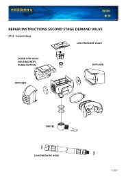
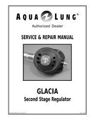
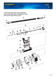
REPAIR INSTRUCTIONS SECOND STAGE DEMAND VALVEEXPLODED VIEWArt. No. 2725, 2941, 2961, 3546Low pressure hose with saftey valveLow pressure valveServo valveHousing completeSwitch
SECOND STAGE2710, 2941, 2961, 3546Removal:1. Disconnect the low pressurehose from the second <strong>stage</strong>.2. Remove the low pressure valvefrom the housing (15) with ascrewdriver. Make sure the servovalve needle is not bent. Be sureto hold the low pressure valvecarefully, to avoid dropping it(see figure).3. Cut off the locking strap (17)with cutting pliers. Remove themouth piece (16).4. Unscrew the 4 screws (26) witha 3.5 mm screwdriver.5. Remove the cover (25) and thediaphragm (24).6. Remove the purge button (27).IMPORTANTThe switch should not beremoved if it is undamaged.Removal:1. Pull out the diaphram cam (22).2. Cut off the switch (18) with apair of cutting pliers close tothe locking washer (21).Remove the switch.3. Remove the o-ring (19).
Removal:1. Remove the servo valve (14).2. Unscrew the stop screw (9) andremove the valve tube (12).Remove the o-rings (11) (13)with an o-ring remover. Makesure the sealing surfaces are notdamaged.3. Remove the rubber plate (10).4. Place the valve housing in thetool. Unscrew the valve housing(4) with a special spanner.5. Remove the o-ring (7) with anoring remover. Make sure thesealing surfaces are notdamaged.6. Remove the valve insert.Sealing surfaces7. Remove the o-rings (5) (3) withan o-ring remover. Make surethe sealing surfaces are notdamaged.
When servicing the regulator the following parts should bereplaced: See chapter Servicekit.1. All o-rings. Also the ones in the low pressure hose.CLEANING:If corrosion or salt deposits occurs, place all metal parts –concentrated Hempocid* or 15% Hydrochloric acid for about 10minutes. Then, rince the parts thoroughly and blow dry with air.The synthetic parts in the second <strong>stage</strong> must not be treated withsolvent. They shall be cleaned in freshwater only.*Hempocid = Acid Liquid Detergent Containing phosphoricacid (5 - 10%) and bactericid for desinfectant cleaning.BEFORE INSTALLING CHECKTHE FOLLOWING:1. Diaphragm (24). Check that thesealing surface of the diaphragm iseven. Also check that there are noholes in the diaphragm and that thediaphragm washer is properly fixed inposition.2. The mouth-piece (16). Make surethere are no cracks.3. The purge button (27). Make surethere are no cracks. Check to make surethe spring is undamaged.4. Servo valve (14). Check to makesure that the valve bar is not bent.5. The switch: Put the switch into - and+position. It should be moved ratherslowly, control the position of thediaphragm and that it is properlytighten.
SECOND STAGEAssembly:341. Mount the o-rings (5,3) on thevalve housing (4). Use the tools.See diagram.2. Install the valve insert (6) in thevalve housing (4).3. Place the o-ring (7) in thegroove of the valve insert (6).Lubricate the thread. Install thevalve housing nut (8).4. Place the valve housing in thehandle. Tighten with a tool.See diagram.
5. Install the o-rings (11,13) on thevalve tube (12). Grease the threadsand the o-rings.6. Screw in the valve tube (12) untilabout 2 mm space remains asillustrated.7. Install the rubber plate (10). Screw inthe set screw (9). Do not tighten up.8. Screw the servo valve (14 ) on tovalve tube (12). Tighten up. Becareful not to bend the valve needle.9. Test the low pressure valve forleakage. See chapter: Finaladjustment.SWITCH1. Fit in o-ring (19) and lubricate it.2. Fit in the switch with the narrowpart against the - minus sign on thesecond <strong>stage</strong> valve. See diagram.3. Install the locking washer (21) onthe switch (18). Press it on a drift.Tighten the locking washer so thatthere is sufficient resistance whensetting the switch.4. Fix the diaphragm cam (22) upon theswitch (18). Set switch at - (minus),press the diaphragm cam intocorrect position per the diagram.The distance from the top of thediaphragm cam to the housing shouldbe 2 mm, concerns diaphragm ofsilicone rubber, see diagram. Carefullypush diaphragm cam into the rightposition. Note the cam should bepushed slowly on to the switch so thatthe switch is not moved.
Assembly:1. Fit the purge button in the cover (25) forthe second <strong>stage</strong>. Make sure that thespring is undamaged.2. Position the diaphragm (24) with thediaphragm washer facing down wardsand the hole positioned as illustrated.3. Position the cover (25) for the second<strong>stage</strong> according to the adjacentillustration. Lubricate the screw andtighten (27) with a screwdriver.4. Install the mouth piece (16) and thelocking strap (17). Tighten up and cutoff with plastic band pliers.5. Checking the second <strong>stage</strong> for leaks:Place the mouth piece against your lipsand cover the low pressure hoseconnection with your thumb and inhalelightly. This will create a partialvacuum inside the second <strong>stage</strong>. If thepressure does not equalize in 5 second<strong>stage</strong> leaks. See chapter fault detecting.LOW PRESSURE HOSEWITH SAFETY VALVECheck the hose for cracks or other defects.Check the sealing surfaces and threads.Install the o-ring (1) and lubricate it.Install the hose in the outlet of the <strong>first</strong><strong>stage</strong> valve marked R (important for theregulators performance). Tighten with 13mm open- end wrench. Oceanair in anoptional outlet marked LP.
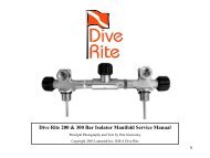
REPAIR INSTRUCTIONS FIRST STAGE REDUCING VALVEEXPLODED VIEWArt. No. 2801, 2808, 2962, 3257, 3580, 3585JETSTREAM - YOKECYKLON 5000 - YOKEANTI-FREEZE CUPDIFFERENT CONNECTIONSECONDARY PARTPRIMARY PARTBALANCING PART
FIRST STAGE VALVE2801, 2808, 2962, 3257,3580, 3585Secondary side:1. Disconnect the low pressurehose from the <strong>first</strong> <strong>stage</strong> valveusing a 13 mm open endwrench.2. Remove the o-ring from the lowpressure hose. Make sure thesealing surfaces are notdamaged.Removal:Place the <strong>first</strong> <strong>stage</strong> valve with thesecondary side facing upwards inthe fixture.1. Remove the pressure adjustingscrew (1) with a 6 mm Allenwrench and remove the spring(2) and (3).2. Remove the cover (4) using a 27mm crowsfoot and the upperdiaphragm centre (5).Sealing surfaces3. Remove the diaphragm. (6).Make sure the sealing surface isnot damaged. Remove the lowerdiaphragm centre (7) and thevalve needle (8).
BALANCE HOUSINGRemoval:Place the <strong>first</strong>-<strong>stage</strong> valve with thebalanced housing facing upwards.1. Steady the balance housingwith a special wrench. Thenremove the blind screw (25)with a 5 mm Allen wrench.Remove the o-ring(24) with ano-ring remover. Remove thebalance housing (21) with thespecial wrench.2. Remove the spring (23) and thespring guidance (22).3. Remove the valve piston (16)and the spacing sleeve (17).Remove the o-ring (18) with ano-ring remover. Remove thewasher (19) and the o-ring (20).Use an o-ring remover for thisalso. Make sure the sealingsurfaces are not damaged.Sealing surfaces
FIRST STAGE2962, 3257, 3580, 3585Removal:1. Remove the protective cap (26).2. Remove the locking screw (27)with a 6 mm Allen wrench.Remove the o-ring (28) and thecupfilter (30).3. Place the <strong>first</strong> <strong>stage</strong> in thefixture. Remove the connecting(3 1) with a 6 mm Allen wrench.4. Remove the wheel (33) and theoring (32) with an o-ringremover. Make sure the sealingsurfaces are not damaged.Sealing surfaces
FIRST STAGE2801Removal:1. Remove the protective cap (3 1).2. Remove the locking screw (27)with an 8.5 mm screwdriver.Remove the cup filter (28).3. Place the <strong>first</strong> <strong>stage</strong> in thefixture. Remove the highpressure valve housing (33) witha 6 mm Allen wrench.4. Remove the wheel (34).5. Remove the o-rings (30,32) withan o-ring remover. Make surethe sealing surfaces are notdamaged.Sealing surfaces
FIRST STAGE2801, 3257 10, 3585 10Removal:1. Remove the protective cap (24).Unscrew the knob (25).2. Remove the locking screw (27)with an 8.5 mm screwdriver.Remove the cup filter (28).3. Remove the connection (29)with a 6 mm Allen wrench.4. New model, remove the lockingscrew (34) with an 6 mm Allenwrench. Remove the cup filter(35) and the o-ring (36). Removethe connection (37) with an 6mm Allen wrench.5. Remove the o-ring (30) with ano-ring remover. Make sure thesealing surface is not damaged.Sealing surfaces
FIRST STAGE2801, 2808, 2962, 3257,3580, 35856. Remove the valve seat (15) with avalve seat remover.7. Remove the o-ring (14) with anoring remover. Make sure thesealing surface is not damaged.8. Remove the valve housing fromthe fixture.9. Remove the blind screw (10 and13) with a 5 mm and 3= Allenwrench. Remove the o-rings (9 and12) with an o-ring remover. Makesure the sealing surfaces are notdamaged.Sealingsurfaces3580, 3585
When servicing the regulator thefollowing parts should be replaced:See chapter Servicekit.1. All o-rings2. Diaphragm3. Cup filter4. Valve seat5. WasherCLEANING:If corrosion or salt deposits occurs,place all metal parts –concentrated Hempocid* or 15%Hydrochloric acid for about 10minutes. Then, rince the partsthoroughly and blow dry with air.The synthetic parts in the second<strong>stage</strong> must not be treated withsolvent. They shall be cleaned infreshwater only.Checking:Check the following parts verycarefully. Replace even if onlyslightly damaged.1. Valve needle (8). Check to makesure that the needle is straight.2. The blind screws (10 and 13).Check to make sure the sealingsurfaces are undamaged. Alsocheck that the threads are notdamaged.
3. The valve housing (11).Check to make sure the threadsand also the sealing surfaces forthe o-rings are undamaged.4. The connections (29,31 or 33).Check to make sure the sealingsurfaces for the o-rings are undamaged.5. Balanced housing (21).Check to make sure the threadsand also the sealing surfaces forthe o-rings are undamaged.
Assembly1. Install the o-rings (9) and (12) onthe blind screws (10) and (13).Lubricate through the outlets.2. Screw in the blind screws in theLP- HP outlets. Use a 5 mm Allenwrench and tighten up by hand.3. Install the o-ring (14) on thevalve seat (15) and the installthe valve seat with a seat drift.Press the drift diagonally asshown in the diagram and the”rock” it to the vertical whilepressing down. The seat ando-ring should pop into place.This procedure avoids damageto the o-ring from the highpressure supply outlet.
FIRST STAGE2962, 3257, 3580, 3585Assembly:1. Install the o-ring (3 1) on theconnection (30). Lubricate theo-ring and the thread.2. Install the wheel (33) on theconnection.3. Screw the wheel connectionassembly into, the valve housingassembly with a 6 mm Allenwrench.Place the valve housing (11) in afixture. Tighten with a torque wrenchto 28 - 30 Nm (20-22 Ibf.ft.).IMPORTANT! Use bits No 3119(L = 40 mm). Put o-ring (29) on thecup type filter (30). Install these ando-ring (28) and the locking screw (27)in connection (31). Tighten with aAllen wrench 6 mm.
FIRST STAGE2801, 3257 10, 3585 10Assembly:1. Install the o-ring (30) on theconnection (29). Lubricate thethread and the o-ring.2. Place the connection (29) in theYoke (26) and screw the connectioninto the valve housing (13)using a 6 mm Allen wrench. Placethe valve housing in a fixture.Tighten with a torque wrench to28 - 30 Nm.(20-22 Ibf.ft). Use bitsno 2883 (length 30 mm)3. Install the cup filter (28). Screw inthe locking screw (27) with a 8.5mm screw driver. Install theprotective cap (24). Grease thethread and screw in the knob.4. New model. Place the connection(37) in the Yoke (39) and screw theconnection into the valve housing,using a 6 mm Allen wrench. Placethe valve housing in a fixture.Tighten with a torque wrench to28 - 30 Nm (20-22 Ibf.ft). Use bitsno 3119 (length 40 mm)5. Install the o-ring(36) on the cuptype filter (35). Place the filter inthe connection(37).6. Install the protective cap, greasethe thread and screw in the knob.
FIRST STAGE2808Assembly:1. Install the o-rings (30, 32) onthe connection (33). Grease theo-ring (30) and thread.2. Fit the connection (33) to thewheel (34) and screw it into thevalve housing (13) with a 6 mmAllen wrench. Place the valvehousing in torque wrench to 28- 30 Nm. (20-22 Ibf.ft).3. Install the cup filter (28) screw inthe locking screw (27) with an8.5 mm screwdriver.
FIRST STAGEBALANCED HOUSING1. Install the o-ring (24) on theblind screw G 1/8’’ (25).2. Grease the inside of balancedhousing (21).3. Install the spring guide (22) andthe spring (23). Screw in theblind screw (11) with a 5 mmAllen wrench. The blind screwshould be tightened while thebalanced housing is held in thevalve housing.4. Install the o-ring (20) at thebalanced housing .5. Install the washer (19) and theo-ring (18). Grease the inside ofo-ring and the washer. Installthe spacing sleeve (17) and thevalve piston (16).6. Install the balanced housing(21) in the valve housing (11)and tighten the blind screwwith a 5 mm Allen wrench.
7. Turn the valve housing with thesecondary side upwards.8. Install the valve needle (10). Atprevious models the needle wasbeveled in one edge. The bevelshould in these cases be pointeddownwards.9. Install the lower diaphragm centre(7) and the diaphragm (6), whichmust be pushed into the groove inthe valve housing. Check to makesure that this is correctly installedby pressing it downwards.It should move approximately2 mm (1/16’’).10. Install the upper diaphragmcentre (5).11. Install the cover (4) and tightenwith a torque wrench to 28 - 30Nm. (20-22 Ibf.ft).12. Install the spring (2) and (3),lubricate both ends of the springand the thread on pressureadjusting screw, and tighten 5turns with a 6 mm Allen wrench.
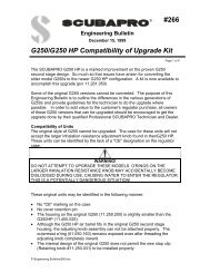
REPAIR INSTRUCTIONS FIRST STAGE REDUCING VALVE3790 - First <strong>stage</strong> G 5/8”3790-10 - First <strong>stage</strong> YOKEANTI-FREEZE CAPDIFFERENT CONNECTIONSYOKEG 5/8’’SAFETY VALVE
FIRST STAGE VALVE3790Secondary side:301. Disconnect the low pressurehose from the <strong>first</strong> <strong>stage</strong> valveusing a 13 mm open endwrench.2. Remove the o-ring (30) from thelow pressure hose with the o-ring remover.First <strong>stage</strong> valve with G 5/8’’:3. Remove the locking screw (22)with a 6 mm Allen wrench.Remove the o-ring (24) and thecup-filter (25) with o-ring (23).First <strong>stage</strong> valve with Yoke:3. Remove the knob (23) and theprotective cap (21). Remove thelocking screw (24) with a 6 mmAllen wrench. Remove the cupfilter (26) and the o-ring (25).4. Place the <strong>first</strong> <strong>stage</strong> valve withthe secondary side facingupwards in the fixture.
FIRST STAGE VALVE3790Removal:1. Remove the pressure adjustingscrew (1) with a 6 mm Allenwrench and remove the spring(2 and 3).2. Remove the cover (4) using a27 mm crowsfoot and the upperdiaphragm center (5).First <strong>stage</strong> valve with G 5/8’’:3. Remove the connection (26)and the wheel (28) with a 6 mmAllen wrench.4. Remove the o-ring (27) with ano-ring remover. Make sure thesealing surfaces are notdamaged.First <strong>stage</strong> valve with Yoke:3. Remove the connection (27)and the yoke (22) with a 6 mmAllen wrench.4. Remove the o-ring (28) with ano-ring remover. Make sure thesealing surfaces are notdamaged.
FIRST STAGE VALVE3790Removal:1. Remove the valve centre, upper (6)and the diaphragm (7).2. Remove the diaphragm centre,lower (8) and the valve needle (9).3. Remove the valve centre, lower(10) and the o-ring (11) with an o-ring remover. Make sure thesealing surfaces are not damaged.4. Remove the o-ring (12), only 3790,from the valve centre, lower (10)with an o-rings remover. Make surethe surfaces are not damaged.5. Remove the valve seat (14) and theo-ring (13) with the assemblydrift A.6. Remove the valve piston (15) andthe pressure spring (16).7. Remove the washer, steel (17), theo-ring (18) and the washer, teflon(19) with an o-ring remover.Make sure the surfaces, are notdamaged.
FIRST STAGE VALVE3790Removal:1. Remove the blind screw (29 and31) with a 5 mm Allen wrench.Remove the o-rings (30 and 32)with an o-ring remover.Make sure the sealing surfacesare not damaged.2. Remove the locking screw (35)with a 4mm Allen wrench.Remove the pressure spring (16)and the valve piston (34).3. Remove the valve sealing (33)from the valve piston (34) withan o-ring remover.Cleaning:If corrosion or salt deposits occurs, place all metal parts in concentrated Hempocid* or 15%Hydrochloric acid for about 10 minutes. Then rinse them thoroughly and blow dry with air. Thesynthetic parts in the second <strong>stage</strong> must not be treated with solvent. They shall be cleaned infreshwater only. *Hempocid = Acid Liquid Detergent Containing phosphoric acid (5-10%) andbactericid for desinfectant cleaning.
FIRST STAGE VALVE,3790When servicing the regulatorthe following parts should bereplaced:(see chapter Servicekit)1. All o-rings2. Diaphragm3. Cup filter4. Valve seat5. Washer6. Valve sealingChecking:Check the following parts to makesure the sealing surfaces areundamaged. Also check that thethreads are not damaged.1. The blind screws (29 and 3 1)2. The valve housing (20)3. Valve centre (10)4. The connections (26 or 27)
FIRST STAGE VALVE3790Assembly:1. Install the o-rings(30 and 32) onthe blind screws (29 and 31).Lubricate the outlets.2. Screw the blind screws in theLP-HP outlets. Use a 5 mmhexagon spanner and tightenup by hand.First <strong>stage</strong> valve with G 5/8’’:1. Install the o-ring (27) on theconnection (26). Lubricate theo-ring and the thread.2. Install the wheel (28) on theconnection.3. Screw the wheel connectionassembly into the valve housingassembly with a 6 mm Allenwrench.First <strong>stage</strong> valve with Yoke:1. Install the o-ring (28) on theconnection (27). Lubricate theo-ring and the thread.2. Install the yoke (22) on theconnection.3. Screw the wheel connectionassembly into the valve housingassembly with a 6 mm Allenwrench.
FIRST STAGE VALVE3790Assembly:1. Lubricate the valve housing (20).2. Place on the assembly drift A:-washer, steel (17)-O-ring (18)-washer, teflon (19)3. Install the valve housing.Lubricate the washersand the o-ring.4. Install the o-ring (13) on thevalve seat (14).125. Install the o-ring (12), on thevalve centre, lower (10).
FIRST STAGE VALVE3790Assembly:1. Place on the assembly fixture B:- valve centre, lowér (10)- o-ring (11), lubricate- valve seat (14) with o-ringdownwards- valve piston (15), lubricate,and pressure spring (16) on valvepiston.2. Install the valve housing (20).3. Turn the valve housing (20) withthe secondary side upwards.4. Install the valve needle (9).5. Install the lower diaphragm centre(8).6. Install the diaphragm (7) in thevalve centre, upper, convex part up(6). Install the valve housing (20).
FIRST STAGE VALVE3790Assembly:1. Install the diaphragm centre,upper (5) in the valve housing(20).2. Grease the thread on the cover(4) and tighten up by hand.3. Check to make sure that theparts are correctly installed bypressing at the valve centre. Itshould move approximately2 mm (1/16’’).4. Lubricate both ends of thespring (2 and 3) and install.Lubricate the thread onpressure adjusting screw (1),and tighten 7 turns with a 6 mmAllen wrench.5. Install the valve sealing (33) onthe valve piston (34).6. Install the valve piston (34) andthe pressure spring (16). Installthe locking screw (35) with a 4mm Allen wrench. Tighten up byhand.
FIRST STAGE VALVE3790Assembly:1. Place the valve housing (20) in afixture.2. Tighten the cover for valvehousing with a torque wrench(30 Nm) and an open endedinsert tool 27 mm.3. Tighten the connection with atorque wrench (30 Nm) andholder insert tool/ bits.IMPORTANT! Use bits nr 3119(L = 40 mm).First <strong>stage</strong> valve with G5/8’’:4. Put o-ring (23) on the cup typefilter (25). Install them and theo-ring (24) and the lockingscrew (22) in the connection(26). Tighten with a Allenwrench 6 mm.First <strong>stage</strong> valve with Yoke:4. Put o-ring (25) on the cup typefilter (26). Install them and thelocking screw (24) in theconnection (27). Tighten with aAllen Wrench 6 mm. Put theprotective cap (21) on the knob(23). Lubricate and screw in theknob.5. Install o-ring (30) on the lowpressure hose. Lubricate the o-ring and the thread. Tighten thehose with a 13 mm openwrench.
TESTING AND ADJUSTMENT OF REGULATORJETSTREAM Art. No. 2960, 3960First <strong>stage</strong> valve:1. Connect the regulator to the test equipment.2. Connect the test manometer hose to one of thelow pressure outlets.3. Open the LP valve (=20 bar).4. Set the secondary pressure at 10 bar, andintermittently purge the second <strong>stage</strong> by meansof the purge button. NOTE that the second <strong>stage</strong>valve must be fully tight during this test. Whenthe pressure gauge needle stops at the presetpressure, a maximum rise in pressure of 1 bar isallowed before the needle finally stops. If theneedle continues to move to a higher pressurereading there is a fault in the seal between thevalve seat and piston or the O-ring.5. Close the LP valve, and open the HP valve(=200/300 bar). Purge intermittently with thepurge button, check the tightness, and adjust thepressure to 8.5-9 bar.Second <strong>stage</strong> valve: Tightness testing of the lowpressure valve withservo valve.1. Close the HP valve and purge fully by means ofthe purge button.2. Remove the low pressure valve from the second<strong>stage</strong> housing.3. Place the low pressure valve in the test fixture andscrew on the hose.4. Open the LP valve, push the servo valve’s needlecarefully, and purge a few times. Immerse thevalve below the surface of the water in a specialwater tank and check to make sure that the valveis absolutely tight.5. Move the low pressure valve to the second <strong>stage</strong>valve and fit the low pressure valve’s outlet to theguide fitting in the second <strong>stage</strong> housing. Makesure that the valve is inserted straight to preventthe servo valve from becoming damaged.6. Lubricate the external thread on the second <strong>stage</strong>housing and the end of the hose nipple. Screw onthe low pressure hose.Adjustment of the inhalation resistance:1. Open the HP valve.2. Connect the oval connecting pipe on theinhalation resistance gauge to the mouth-pieceon the regulator.3. Test-breathe very carefully. Check the reading ofthe gauge needle, which should rise to 35-40mm/vp and then move back. The turning pointreading equals the inhalation resistance. If thereading is too low, screw the valve tube awayfrom the diaphragm as shown in the illustration. Ifthe reading is too high, screw the valve tubetowards the diaphragm.Checking the purge button:1. Press the purge button. The second <strong>stage</strong> valveshould now provide a generous supply of air.2. Cover the mouth-piece and press the purgebutton. The second <strong>stage</strong> valve should thensupply a reduced flow air.
TESTING AND ADJUSTMENT OF THE REGULATOROCEANAIR Art. No. 2940First <strong>stage</strong> valve:1. Connect the regulator to the test equipment.2. Connect the test manometer hose to one of thelow pressure outlets.3. Open the LP valve (=20 bar).4. Set the secondary pressure at 11.5 bar, andintermittently purge the second <strong>stage</strong> by meansof the purge button. NOTE that the second <strong>stage</strong>valve must be fully tight during this test. Whenthe pressure gauge needle stops at the presetpressure, a maximum rise in pressure of 1 bar isallowed before the needle finally stops. If theneedle continues to move to a higher pressurereading there is a fault in the seal between thevalve seat and piston or the O-ring.5. Close the LP valve, and open the HP valve(=200/300 bar). Purge intermittently with thepurge button, check the tightness, and adjust thepressure to 8.5-9 bar.Second <strong>stage</strong> valve: Tightness testing of the lowpressure valve with servo valve.1. Close the HP valve and purge fully by means ofthe purge button.2. Remove the low pressure valve from the second<strong>stage</strong> housing.3. Place the low pressure valve in the test fixture andscrew on the hose.4. Open the LP valve, push the servo valve’s needlecarefully, and purge a few times. Immerse thevalve below the surface of the water in a specialwater tank and check to make sure that the valveis absolutely tight.5. Move the low pressure valve to the second <strong>stage</strong>valve and fit the low pressure valve’s outlet to theguide fitting in the second <strong>stage</strong> housing. Makesure that the valve is inserted straight to preventthe servo valve from becoming damaged.6. Lubricate the external thread on the second <strong>stage</strong>housing and the end of the hose nipple. Screw onthe low pressure hose.Adjustment of the inhalation resistance:1. Open the HP valve.2. Connect the oval connecting pipe on the inhalationresistance gauge to the mouth-piece on theregulator.3. Test-breathe very carefully. Check the reading ofthe gauge needle, which should rise to 35-40mm/vp and then move back. The turning pointreading equals the inhalation resistance. If thereading is too low, screw the valve tube awayfrom the diaphragm as shown in the illustration. Ifthe reading is too high, screw the valve tubetowards the diaphragm.Checking the purge button function:1. Press the purge button. The second <strong>stage</strong> valveshould now provide a generous supply of air.2. Cover the mouth-piece and press the purgebutton. The second <strong>stage</strong> valve should thensupply a reduced flow of air.
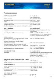
Poseidon Cyklon 300BREATHING REGULATOR Art. No 2980Primary pressure................................................................................Max. 4350 PSI / 300 barSecondary pressure ..........................................................................Max. 181 PSI / 12.5 barAir flow ..................................................................................................Approximately 800 l/minInhalation resistance at 115 l/min...............................................Max. 40 mm of waterExhalation resistance .......................................................................Max. 20 mm of waterThe above data apply when measuring at atmospheric pressureFIRST STAGE VALVE Art. No 3070Description...........................................................................................Diaphgram-operated,compensatedConnection threads for primary pressure................................G 5/8’’ -max. 4350 PSI / 300 barOutlet connections:Four outlets marked LP for second <strong>stage</strong>,drysuits, buoyancy compensators, hookahsupply, safety second <strong>stage</strong>, etc ...................................................UNF 3/8’’ -secondary pressureOne outlet marked HP.....................................................................UNF 7/16’’-primary pressureSECOND STAGE VALVEType designation ...............................................................................Art. No 1133, 3536Description...........................................................................................Downstream type, diaphragm actuated.Integral saftey valve opens atapproximatley 203 PSI / 14 bar.Purge button for clearing.REGULATOR HOSE Art. No 2946Length....................................................................................................28 inch / 70 cmTIGHTENING TORGQUEPrimary connection ..........................................................................20-22 Ibf.ft / 28-30 NmValve cover...........................................................................................20-22 Ibf.ft / 28-30 NmConnections marked LP-HP...........................................................6 Ibf.ft / 8 NmANTI-FREEZE PROTECTIONType designation ...............................................................................Art. No 1286Type ........................................................................................................Rubber cap
Poseidon Cyklon 5000BREATHING REGULATOR Art. No 2950Primary pressure................................................................................Max. 4350 PSI / 300 barSecondary pressure ..........................................................................Max. 174 PSI / 12 barAir flow ..................................................................................................Approx. 1050 l/minInhalation resistance at 115 l/min...............................................Max. 40 mm of waterExhalation resistance ......................................................................Max. 20 mm of waterThe above data apply when measuring at atmospheric pressureFIRST STAGE VALVE Art. No 3257, 3585Description...........................................................................................Diaphgram-actuated, balanced.Connecting threads for primary pressure................................G 5/8 -max 4350 PSI /300 bar accord.SS 2600/K and DIN 477/5 or yoke connectionaccord. SS 2603 and ANSI/CGA VI: 1987Outlet connections:One outlet marked R for second <strong>stage</strong> (max airflow)..........UNF 3/8’’ - secondary pressureThree outlets marked LP for drysuits, buoyancycompensators, hookah supply, safety second <strong>stage</strong> etc.....UNF 3/8’’ -secondary pressureOne outlet marked S has restricted airflowand therefore is intended only for dry-suit or stabjacket ..Intended for <strong>first</strong> <strong>stage</strong> No. 3585UNF 3/8’’ -secondary pressureOne outlet marked HP for pressure gauge..............................UNF 7/16’’ -primary pressureSECOND STAGE VALVE Art. No 1133Description...........................................................................................Downstream-type, diaphragm actuated.Integral safety opens with approximately203 PS1/14 bar. Purge button for clearing.REGULATOR HOSELength....................................................................................................28 inch / 70 cmTIGHTENING TORQUEPrimary connection ..........................................................................20 - 22 Ibf.ft / 28-30 NmValve cover...........................................................................................20 - 22 Ibf.ft / 28-30 NmConnections marked R-LP-HP.......................................................6 Ibf.ft / 10 NmANTI-FREEZE PROTECTIONType designation ...............................................................................Art. No 1286Type ........................................................................................................Rubber cap
Poseidon Cyklon 5000BREATHING REGULATOR Art. No 3950Primary pressure................................................................................Max. 4350 PSI / 300 barSecondary pressure ..........................................................................Max. 174 PSI / 12 barAir flow ..................................................................................................Approx. 1050 l/minInhalation resistance at 115 l/min...............................................Max. 40 mm of waterExhalation resistance .......................................................................Max. 20 mm of waterThe above data apply when measuring at atmospheric pressureFIRST STAGE VALVE Art. No 3720, 3720 10Description...........................................................................................Diaphgram-actuated balanced with shearventuri boost. Release pressure approx.217-247 PSI / 1,5-1,7 MPa / 15-17 barConnecting threads for primary pressure................................G 5/8’’-max 4350 PSI / 30 MPa / 300 baraccord. SS 2600/K and DIN 477/5 oryoke connection accord. SS 2603 andANSI/CGA V1: 1987Outlet connections:One outlet marked R for second <strong>stage</strong> (max. airflow) UNF 3/8’’ -secondary pressureThree outlets marked LP for Cyklon octopus,drysuits, stadjacket............................................................................UNF 3/8’’ -secondary pressureTwo outlet marked HP for pressure gauge..............................UNF 7/16’’ -primary pressureSECOND STAGE VALVE Art. No 1133, 3536Description...........................................................................................Downstream-type, diaphragm actuated.Integral safety opens with approximately203 PSI/14 bar. Purge button for clearing.REGULATOR HOSE Art. No 2946Length....................................................................................................28 inch / 70 cmTIGHTENING TORQUEPrimary connection, valve cover..................................................22 Ibf. ft / 30 Nm / 3,0 kpmConnections marked R-LP-HP.......................................................6 Ibf.ft / 8 Nm, / 0,8 kpmANTI-FREEZE PROTECTIONType designation ...............................................................................Art. No 1286Type ........................................................................................................Rubber cap
REPAIR INSTRUCTIONS SECOND STAGE DEMAND VALVEEXPLODED VIEWSECOND STAGE 1133Low pressure hoseLow pressure valveMouth-pieceMouth-piece tubeDiaphram house
SECOND STAGE1133, 3224, 3354, 3536Removal:1. Disconnect the low pressurehose from the second <strong>stage</strong>with a 17 mm. open wrench.Remove the oring (2) with ano-rings remover.2. Remove the diaphragm housing(27) from the mouth piece tube.3. To release the exhalation cover,remove the locking ring with asmall screwdriver.4. Remove the exhalationdiaphragm (21).
1. Remove the locking ring (25)with an awl. Support thediaphragm house, see diagram.Make sure that the sealingsurface for the exhalationdiaphragm is not damaged.2. Remove the cover (24) and theinhalation diaphragm (23).Removal: Push out the purgebuttonIMPORTANT! The purge button(26) should not be removed if itis undamaged3. Remove the connecting ring (4)and the low pressure valve (15).
1. Cut off the locking strap (17)with cutting pliers.2. Remove the mouth-piece (16)and the o-ring (12).1. Remove the lever pin (11).2. Remove the operating device(14).3. Remove the o-ring (12).4. Unserew the valve seat (5) withan 8.5 mm screwdriver. NOTE!the valve seat has a very fragiletightening edge; put the seatwith the edge upwards.5. Remove the valve piston (8) andthe spring (9). In order toprotect the piston bond, the oldrubber plate should be keptuntil the new shall be fixed.6. Remove the o-ring (6) with anoring remover. Make sure thesealing surfaces ar notdamaged.IMPORTANT! The ejector sleeveshould not be removed if it isfunctional and undamaged.Check to see that the sleeve canbe rotated to any position, butthat it does not rotate freely.
When servicing the regulator thefollowing parts should be replaced:See chapter Servicekit.1. All o-rings, including the one inthe low-pressure hose.2. Rubber plate (7).CLEANING:If corrosion or salt deposits occurs, place all metalparts – concentrated Hempocid* or 15% Hydrochloricacid for about 10 minutes. Then, rince the partsthoroughly and blow dry with air. The synthetic partsin the second <strong>stage</strong> must not be treated with solvent.They shall be cleaned in freshwater only.*Hempocid = Acid Liquid Detergent Containingphosphoric acid (5 - 10%) and bactericid fordesinfectant cleaning.BEFORE INSTALLING CHECK THEFOLLOWING:1. Diaphragms (21) (23). Check the sealing surface ofthe diaphragm to see if it is even and uncracked.2. The mouth-piece (16).Make sure that there are no cracks.3. The purge button (26).Make sure there are no cracks.4. Valve piston (8). Ensure that the ball joint isworking correctly by manipulating and rotatingthe joint.5. Operating device (14). Make sure that the jointarticulates smoothly. Important: The operatingdevice must be replaced, if the lever tab is bent.The tab should not be straightened, as this wouldweaken it and make subsequent failure possible.6. Valve seat (5). Check to make sure the sealingsurfaces are undamaged.7. Low pressure hose (3). Check to make sure that thesealing surface is undamaged, and that the rubberdoes not show any flaws.8. Diaphragm housing (22). Make sure that thesealing surfaces are free from defeas and that thetrack for the inhalation diaphragm is absolutelyclean and free from lubricant.
Assembly:Install the ejector sleeve (13) on thevalve housing (10). Press the sleeve intothe low pressure valve so the slits ofthe sleeve are exceedingly small.Lubricate:Grease:Sealing surfacesOil:1. Install the o-ring (6) on the valve seat(5). Make sure that the sealingsurface is not damaged.2. Lubricate the ball joint. Tilt theposition head according to thefigure to ensure that it rotates andarticulates smoothly.3. Remove the rubber plate (7) with anawl and make sure the sealingssurface on the valve is clean. Installthe new rubber plate.4. Put the spring (9) on the valvepiston (8). Lubricate the spring5. Install the valve piston/spring in thevalve housing with the flat part ofthe valve piston upwards.
1. Place the valve housing on adrift seated on a block.Press the valve housing down,compressing the spring. Keepthe flat part of the valve pistonparallel with the horizontal slotin the end of the valve housing.Move the valve piston up anddown a few times to check forfreedom of movement.2. Press the valve housing downand slide an o-ring removerthrough the hole in the valvepiston. See diagram.3. Lubricate the o-ring and thethread of the valve seat. Screwin the valve seat with an 8.5 mmscrew driver until the o-ringremover comes loose.4. Install the operating device (14).Insert the lever pin (11) throughthe slot, engaging the hole inthe operating device. Rotate thelever pin 90 degrees to lock it inplace.
1. Install the o-ring (12).Lubricate. See diagram.2. Install the mouth piece (16) andthe plastic band (17). Tightenand cut off plasticband withplastic band pliers.3. Install the o-ring .(12)4. Lubricate the threads on themouth piece5. Install the low pressure valve(15) in the mouth piece tube.Set the indent notch at the topof the valve housing against thekey at the top of the mouthpiece tube. Screw on theconnecting ring (4).6. Screw the valve seat down untilthe highest part of theoperating device is even withthe level og the opening of themouth piece tube. Hold thesecond <strong>stage</strong> valve vertically.See fig.
1. Install the purge button (26) inthe cover (24).Screw the buttonin the cover-cavity2. Install the inhalation diaphragm(23) on the diaphragm housing(22).3. Seat the lip on the diaphragminto the recess on the inner rimof the diaphragm housing. Usean o-ring remover or otherblunt pointed instrument.4. Set the inhalation cover (24) onthe diaphragm housing over thediaphragm.5. Place the diaphragm housingcomplete with diaphragm andcover into the frame of theassembly tool.6. Insert the locking ring (25) intothe upper groove of the press ofthe assembly tool. See diagram7. Place the press on top on thediaphragm housing.8. Tum the knob until you hear orfeel a slight click. Continueturning until you encounterresistance, then back off theknob to release the housing.9. Check the locking ringplacement to make sure that ithas completely entered thegroove.
1. Install the exhalation diaphragm(21) on the diaphragm housing.Control that the diaphragm ispacking on the diaphragmhousing.2. Install exhalation diaphragmcover (20) and locking ring (19).3. Install the diaphragm housingon the mouthpiece tube. Besure to slip the operating deviceinto the diaphragm guidesleeve.4. Checking the second <strong>stage</strong> forleaks: Place the mouth pieceagainst your lips the lowpressure hose correction withyour thumb and inhale lightly.This will create a partial vacuuminside the second <strong>stage</strong>. If thepressure does not equalize in 5seconds the second <strong>stage</strong> leaks.See chapter Fault-tracingscheme.5. Install the o-ring (2) on the LPhose and lubricate6. Screw on the LP-hose. Do nottighten the connecting ringuntil after the function test.
REPAIR INSTRUCTIONS FIRST STAGE REDUCING VALVEEXPLODED VIEWArt. No. 2305, 2422, 3070ANTIFREEZE CUPSECONDARY PARTPRIMARY PARTYOKE CONNECTION
FIRST STAGE VALVE2305, 2422, 3070Secondary side:Removal:Place the <strong>first</strong>-<strong>stage</strong> valve in fixturewith the secondary side facingupwards.1. Remove the pressure adjustingscrew (1) with a 6 mm hexagonspanner, and remove the spring(2) and (3).2. Remove the cover (4) using a 27mm crowsfoot wrench. Removethe upper diaphragm center (5).3. Remove the diaphragm (6) withan o-ring remover. Make surethe sealing surface is notdamaged. Remove the lowerdiaphragm center (7) and thevalve needle (8).
FIRST STAGE3070 (2422)1. Remove the locking screw (23) with a 6mm Allen wrench. 20 Remove the o-ring (24), cup filter (21) and o-ring (22).2. Place the <strong>first</strong> <strong>stage</strong> in the fixture.Remove the connection (20) with 6 mmAllen wrench.3. Remove the wheel (18) and the o-ring(19) with an o-ring remover. Make surethe sealing surfaces are not damaged.4. Remove the spring (17) and the valvepiston (16).5. Disconnect the low pressure hose fromthe <strong>first</strong>-<strong>stage</strong> valve with a 13 mmopen-end wrench.6. Remove the o-ring from the lowpressure hose. Make sure the sealingsurfaces are not damaged.FIRST STAGE23051. Remove the o-ring (20) with an o-ringremover. Make sure the sealing surfacesare not damaged.2. Remove the locking screw (19) with a8.5 mm screwdriver. Remove the cuptype filter (18).3. Place the <strong>first</strong> <strong>stage</strong> housing in thefixture. Remove the connection (17)using a 6 mm Allen wrench.4. Remove the o-ring (15) with an o-remover. Make sure the sealing surfacesare not damaged.5. Remove the wheel (16).6. Remove the spring (14) and the valvepiston (13).7. Disconnect the low pressure hosefrom the <strong>first</strong> <strong>stage</strong> valve with a 13mm openend wrench.8. Remove the o-ring from the lowpressure hose. Make sure the sealingsurfaces are not damaged.
1. Remove the valve seat (15) withthe valve seat remover.2. Remove the o-ring (14) with ano-ring remover. Make sure thatthe sealing surfaces are notdamaged.Sealing surfaces3. Remove the blind screws (9)and (13) with a 5 mm Allenwrench. Remove the o-ringswith an o-ring remover. Makesure that the sealing surfacesare not damaged.Old-type fist <strong>stage</strong> valve housingswith (G 1/8”) threads are equippedwith nylon gaskets seats.It is not normally necessary tochange these seats during service.However, if the seats are subjectedto a great deal of over-tightening,the interior orfices can be reducedin diameter, significantly reducingflow and performance. Compareinstalled gasket orifices with a newgasket, and replace as necessary.Gaskets must also be replacedafter a long time acid-bath.a. G1/8’’-port with gasket.b. UNF 3/8’’-port with o-ring
When servicing the regulator followingparts should be replaced:See chapter Servicekit.1. All o-rings2. Diaphragm3. Cup filter4. Valve seatCleaning:If corrosion or salt deposits are inevidence, place all metal parts in 15percent hydro-chloric acid. They should beleft in the acid for about 10-15 minutes.Then, rinse the parts thoroughly and blowdry with air.SERVICE INSTRUCTIONSChecking:Check the following parts very carefully.Replace even if only slightly damaged.Valve needle (8). Check to make sure thatthe needle is straight.The blind screws (9) and (13), check tomake sure the sealing surfaces areundamaged. Also check that the threadsare not damaged.The valve housing (11), check to makesure the threads and also the sealingsurfaces for the o-rings are undamaged.The connections (17) or (20), check tomake sure the sealing surfaces for theo-rings are undamaged.
AssemblyLubricant:Grease:1. Install the o-ring (10) on the blindscrews (9), low pressure supply and theo-ring (12) on the blind screw (13), highpressure supply. Lubricate the blindscrews and the o-rings.2. Screw in the blind screws in theLP-HP outlets. Use a 5 mm Allenwrench an tighten hard.3. Install the o-ring (14) on the valveseat (15) and then install the valveseat with a seat drift.4. Lubricate the point of the valve needle(8) and install it in the lower diaphragmcenter (7). (The grease will help retainthe needle on the lower diaphragmcenter during the assembly process).5. Install needle (8) and center (7) inthe valve housing.6. Press the diaphragm (6) into thegroove of the valve housing. Use ablunt-pointed instrument to set itfirmly in place.NOTE:The diaphragm (6) must be replaced onevery removal.7. Reverse the valve housing.8. Install the valve piston (16) on thevalve needle.9. Install the spring (17) on the valvepiston.
FIRST STAGE3070, 24221. Install the o-ring (19) on theconnection housing (20). Lubricatethe o-ring and the thread2. Install the wheel (18) on the connection (20).3. Screw the wheel connectionassembly into the valve housingassembly with a 6 mm Allenwrench. Reverse the valvehousing. Check the movement ofthe valve piston by pressing hardon the diaphragm. The movementshould be about 1.5 mm (1/16”).FIRST STAGE23051. Install the wheel (16) on theconnection (17). Install the o-ring(15) on the connection (17).Lubricate the o-ring and thethread2. Screw the wheel connectionassembly into the valve housingassembly with a 6 mm Allenwrench. Reverse the valvehousing. Check the movement ofthe valve piston by pressing hardon the diaphragm. The movementshould be about 1.5 mm (1/16”).
1. Place the upper diaphragmcenter (5) on the diaphragm inthe valve housing.2. Screw the cover (4) into thevalve housing.3. Lubricate both ends of thespring (2) and (3). Lubricate thethreads on the pressureadjusting screw(1).4. Tighten the pressure adjustingscrew about 5 turns with a 6mm Allen wrench.Place the <strong>stage</strong> assembly in thefixture. Tighten the valve housingcover with a 27 mm crowsfoot andthe connection with a 6 mm Allenwrench. use a torque wrench toachieve 28-30 Nrn (20-22 Ibf.ft) oftorsion.IMPORTANT NOTE: Use the rightbits: To all <strong>first</strong> <strong>stage</strong>s with wheelconnection, bits No. 3119 (length40 mm) should be used.
FIRST STAGE3070, 24221. Install the o-ring (22) on the cuptype 21), then install the lockingscrew and o-ring (23). Tightenwith a 6 mm Allen wrench.FIRST STAGE23051. Install the cup filter (18) andthe locking screw (19) with a8.5 mm screwdriver.Install the o-ring (20).2. Install the o-ring (9) on the LPhose. Lubricate the o-ring andthe thread. Tighten the hosenipple with a 13 mm openendwrench.INSTALLMENT OF ANTIFREEZE CAP1. Check valve cover for correct tightness - 28-30 Nm.(20-22 lbf.ft)2. Blow the inside of the valve cover clean and dry.3. Then fill the valve cover and the rubber with purespirit (alcohol, vodka) or water/glycol mixture. 3/4 fill.4. Install the anti-freeze cap and fasten it with the locking band.
OLD TYPEFor assembly of old-type springhousing, please note the following:1. The upper diaphragm centremust be centered in the midpart.2. The inner and outer secondarysprings shall be set in themiddle.3. Screw carefully on the coverwith assembly screw.4. Tighten the valve housing coverwith a special tool No. 2318. Usea torque wrench to achieve 28Nm (20 Ibf.ft).
REPAIR INSTRUCTIONS FIRST STAGE REDUCING VALVEEXPLODED VIEWArt. No. 2801, 2808, 2962, 3257, 3580, 3585JETSTREAM - YOKECYKLON 5000 - YOKEANTI-FREEZE CUPDIFFERENT CONNECTIONSECONDARY PARTPRIMARY PARTBALANCING PART
FIRST STAGE VALVE2801, 2808, 2962, 3257,3580, 3585Secondary side:1. Disconnect the low pressurehose from the <strong>first</strong> <strong>stage</strong> valveusing a 13 mm open endwrench.2. Remove the o-ring from the lowpressure hose. Make sure thesealing surfaces are notdamaged.Removal:Place the <strong>first</strong> <strong>stage</strong> valve with thesecondary side facing upwards inthe fixture.1. Remove the pressure adjustingscrew (1) with a 6 mm Allenwrench and remove the spring(2) and (3).2. Remove the cover (4) using a 27mm crowsfoot and the upperdiaphragm centre (5).Sealing surfaces3. Remove the diaphragm. (6).Make sure the sealing surface isnot damaged. Remove the lowerdiaphragm centre (7) and thevalve needle (8).
BALANCE HOUSINGRemoval:Place the <strong>first</strong>-<strong>stage</strong> valve with thebalanced housing facing upwards.1. Steady the balance housingwith a special wrench. Thenremove the blind screw (25)with a 5 mm Allen wrench.Remove the o-ring(24) with ano-ring remover. Remove thebalance housing (21) with thespecial wrench.2. Remove the spring (23) and thespring guidance (22).3. Remove the valve piston (16)and the spacing sleeve (17).Remove the o-ring (18) with ano-ring remover. Remove thewasher (19) and the o-ring (20).Use an o-ring remover for thisalso. Make sure the sealingsurfaces are not damaged.Sealing surfaces
FIRST STAGE2962, 3257, 3580, 3585Removal:1. Remove the protective cap (26).2. Remove the locking screw (27)with a 6 mm Allen wrench.Remove the o-ring (28) and thecupfilter (30).3. Place the <strong>first</strong> <strong>stage</strong> in thefixture. Remove the connecting(3 1) with a 6 mm Allen wrench.4. Remove the wheel (33) and theoring (32) with an o-ringremover. Make sure the sealingsurfaces are not damaged.Sealing surfaces
FIRST STAGE2801Removal:1. Remove the protective cap (3 1).2. Remove the locking screw (27)with an 8.5 mm screwdriver.Remove the cup filter (28).3. Place the <strong>first</strong> <strong>stage</strong> in thefixture. Remove the highpressure valve housing (33) witha 6 mm Allen wrench.4. Remove the wheel (34).5. Remove the o-rings (30,32) withan o-ring remover. Make surethe sealing surfaces are notdamaged.Sealing surfaces
FIRST STAGE2801, 3257 10, 3585 10Removal:1. Remove the protective cap (24).Unscrew the knob (25).2. Remove the locking screw (27)with an 8.5 mm screwdriver.Remove the cup filter (28).3. Remove the connection (29)with a 6 mm Allen wrench.4. New model, remove the lockingscrew (34) with an 6 mm Allenwrench. Remove the cup filter(35) and the o-ring (36). Removethe connection (37) with an 6mm Allen wrench.5. Remove the o-ring (30) with ano-ring remover. Make sure thesealing surface is not damaged.Sealing surfaces
FIRST STAGE2801, 2808, 2962, 3257,3580, 35856. Remove the valve seat (15) with avalve seat remover.7. Remove the o-ring (14) with anoring remover. Make sure thesealing surface is not damaged.8. Remove the valve housing fromthe fixture.9. Remove the blind screw (10 and13) with a 5 mm and 3 mm Allenwrench. Remove the o-rings(9 and 12) with an o-ring remover.Make sure the sealing surfaces arenot damaged.Sealingsurfaces3580, 3585
When servicing the regulator thefollowing parts should be replaced:See chapter Service-kit.1. All o-rings2. Diaphragm3. Cup filter4. Valve seat5. WasherCLEANING:If corrosion or salt deposits occurs,place all metal parts – concentratedHempocid* or 15% Hydrochloric acidfor about 10 minutes. Then, rince theparts thoroughly and blow dry with air.The synthetic parts in the second <strong>stage</strong>must not be treated with solvent. Theyshall be cleaned in freshwater only.*Hempocid = Acid Liquid DetergentContaining phosphoric acid (5 - 10%)and bactericid for desinfectant cleaning.Checking:Check the following parts verycarefully. Replace even if only slightlydamaged.1. Valve needle (8). Check to makesure that the needle is straight.2. The blind screws (10 and 13).Check to make sure the sealingsurfaces are undamaged. Alsocheck that the threads are notdamaged.
3. The valve housing (11).Check to make sure the threadsand also the sealing surfaces forthe o-rings are undamaged.4. The connections (29,31 or 33).Check to make sure the sealingsurfaces for the o-rings are undamaged.5. Balanced housing (21).Check to make sure the threadsand also the sealing surfaces forthe o-rings are undamaged.
Assembly1. Install the o-rings (9) and (12) onthe blind screws (10) and (13).Lubricate through the outlets.2. Screw in the blind screws in theLP- HP outlets. Use a 5 mm Allenwrench and tighten up by hand.3. Install the o-ring (14) on thevalve seat (15) and the installthe valve seat with a seat drift.Press the drift diagonally asshown in the diagram and the”rock” it to the vertical whilepressing down. The seat ando-ring should pop into place.This procedure avoids damageto the oring from the highpressure supply outlet.
FIRST STAGE2962, 3257, 3580, 3585Assembly:1. Install the o-ring (3 1) on theconnection (30). Lubricate theo-ring and the thread.2. Install the wheel (33) on theconnection.3. Screw the wheel connectionassembly into, the valve housingassembly with a 6 mm Allenwrench.Place the valve housing (11) in afixture. Tighten with a torque wrenchto 28 - 30 Nm (20-22 Ibf. ft.).IMPORTANT! Use bits No 3119(L = 40 mm). Put o-ring (29) on thecup type filter (30). Install these ando-ring (28) and the locking screw (27)in connection (31). Tighten with aAllen wrench 6 mm.
FIRST STAGE2801, 3257 10, 3585 10Assembly:1. Install the o-ring (30) on theconnection (29). Lubricate thethread and the o-ring.2. Place the connection (29) in theYoke (26) and screw the connectioninto the valve housing (13)using a 6 mm Allen wrench. Placethe valve housing in a fixture.Tighten with a torque wrench to28 - 30 Nm.(20-22 Ibf.ft). Use bitsnr 2883 (length 30 mm)3. Install the cup filter (28). Screw inthe locking screw (27) with a 8.5mm screw driver. Install theprotective cap (24).Grease thethread and screw in the knob.4. New model. Place the connection(37) in the Yoke (39) and screw theconnection into the valve housing,using a 6 mm Allen wrench. Placethe valve housing in a fixture.Tighten with a torque wrench to28 - 30 Nm (20 - 22 Ibf.ft). Use bitsnr 3119 (length 40 mm)5. Install the o-ring(36) on the cuptype filter(35). Place the filter inthe connection(37).6. Install the protective cap, greasethe thread and screw in the knob.
FIRST STAGE2808Assembly:1. Install the o-rings (30,32) onthe connection (33). Grease theo-ring (30) and thread.2. Fit the connection (33) to thewheel (34) and screw it into thevalve housing (13) with a 6 mmAllen wrench. Place the valvehousing in torque wrench to 28- 30 Nm.(20-22 Ibf.ft).3. Install the cup filter (28) screw inthe locking screw (27) with an8.5 mm screwdriver.
FIRST STAGEBALANCED HOUSING1. Install the o-ring (24) on theblind screw G 1/8’’ (25).2. Grease the inside of balancedhousing (21).3. Install the spring guide (22) andthe spring (23). Serew in theblind screw (11) with a 5 mmAllen wrench. The blind screwshould be tightened while thebalanced housing is held in thevalve housing.4. Install the o-ring (20) at thebalanced housing .5. Install the washer (19)and theoring (18). Grease the inside oforing and the washer. Install thespacing sleeve (17) and thevalve piston (16).6. Install the balanced housing(21) in the valve housing (11)and tighten the blind screwwith a Allen wrench to 1ONm/7Ibf.ft.
7. Turn the valve housing with thesecondary side upwards.8. Install the valve needle (10). Atprevious models the needle wasbeveled in one edge. The bevelshould in these cases be pointeddownwards.9. Install the lower diaphragm centre(7) and the diaphragm (6), whichmust be pushed into the groove inthe valve housing. Check to makesure that this is correctly installedby pressing it downwards.It should move approximately2 mm (1/16’’).10. Install the upper diaphragmcentre (5).11. Install the cover (4) and tightenwith a torque wrench to 28 - 30Nm. (20-22 Ibf.ft).12. Install the spring (2) and (3),lubricate both ends of the springand the thread on pressureadjusting screw, and tighten 5turns with a 6 mm Allen wrench.
REPAIR INSTRUCTIONS FIRST STAGE REDUCING VALVE37203720 10ANTI-FREEZE CAPDIFFERENT CONNECTIONSYOKEG 5/8’’SAFETY VALVE
FIRST STAGE VALVE3720Secondary side:301. Disconnect the low pressurehose from the <strong>first</strong> <strong>stage</strong> valveusing a 13 mm box spanner.2. Remove the o-ring (30) from thelow pressure hose with the o-ring remover.First <strong>stage</strong> valve with G 5/8’’:3. Remove the locking screw (22)with a 6 mm Allen wrench.Remove the o-ring (24) and thecup-filter (25) with o-ring (23).First <strong>stage</strong> valve with Yoke:3. Remove the knob (23) and theprotective cap (21). Remove thelocking screw (24) with a 6 mmAllen wrench. Remove the cupfilter (26) and the o-ring (25).4. Place the <strong>first</strong> <strong>stage</strong> valve withthe secondary side facingupwards in the fixture.
FIRST STAGE VALVE3720Removal:1. Remove the pressure adjustingscrew (1) with a 6 mm Allenwrench and remove the spring(2 and 3).2. Remove the cover (4) using a27 mm crowsfoot and the upperdiaphragm center (5).First <strong>stage</strong> valve with G 5/8’’:3. Remove the connection (26)and the wheel (28) with a 6 mmAllen wrench.4. Rernove the o-ring (27) with ano-ring remover. Make sure thesealing surfaces are notdamaged.First <strong>stage</strong> valve with Yoke:3. Remove the connection (27)and the yoke (22) with a 6 mmAllen wrench.4. Remove the o-ring (28) with ano-ring remover. Make sure thesealing surfaces are notdamaged.
FIRST STAGE VALVE3720Removal:1. Remove the valve centre, upper (6)and the diaphragm (7).2. Remove the diaphragm centre,lower (8) and the valve needle (9).3. Remove the valve centre, lower(10) and the o-ring (11) with an o-ring remover. Make sure thesealing surfaces are not damaged.4. Remove the valve seat (14) and theo-ring (13) with the assemblydrift A.5. Remove the valve piston (15) andthe pressure spring (16).6. Remove the washer, steel (17), theo-fing (18) and the washer, teflon(19) with an o-ring remover.Make sure the surfaces, are notdamaged.
FIRST STAGE VALVE3720Removal:1. Remove the blind screw (29 and31) with a 5 mm Allen wrench.Remove the o-rings (30 and 32)with an o-ring remover.Make sure the sealing surfacesare not damaged.2. Remove the locking screw (35)with a 4mm Allen wrench.Remove the pressure spring (16)and the valve piston (34).3. Remove the valve sealing (33)from the valve piston (34) withan o-ring remover.Cleaning:If corrosion or salt deposits occurs, place all metal parts in concentrated Hempocid* or 15%Hydrochloric acid for about 10 minutes. Then rinse them thoroughly and blow dry with air. Thesynthetic parts in the second <strong>stage</strong> must not be treated with solvent. They shall be cleaned infreshwater only. *Hempocid = Acid Liquid Detergent Containing phosphoric acid (5-10%) andbactericid for desinfectant cleaning.
FIRST STAGE VALVE,3720When servicing the regulatorthe following parts should bereplaced:(see chapter Servicekit)1. All o-rings2. Diaphragm3. Cup filter4. Valve seat5. Washer6. Valve sealingChecking:Check the following parts to makesure the sealing surfaces areundamaged. Also check that thethreads are not damaged.1. The blind screws (29 and 3 1)2. The valve housing (20)3. Valve centre (10)4. The connections (26 or 27)
FIRST STAGE VALVE3720Assembly:1. Install the o-rings(30 and 32) onthe blind screws (29 and 31).Lubricate the outlets.2. Screw the blind screws in theLP-HP outlets. Use a 5 mm Allenwrench and tighten up by hand.First <strong>stage</strong> valve with G 5/8’’:1. Install the o-ring (27) on theconnection (26). Lubricate theo-ring and the thread.2. Install the wheel (28) on theconnection.3. Screw the wheel connectionassembly into the valve housingassembly with a 6 mm Allenwrench.First <strong>stage</strong> valve with Yoke:1. Install the o-ring (28) on theconnection (27). Lubricate theo-ring and the thread.2. Install the yoke (22) on theconnection.3. Screw the wheel connectionassembly into the valve housingassembly with a 6 mm Allenwrench.
FIRST STAGE VALVE3720Assembly:1. Lubricate the valve housing (20).2. Place on the assembly drift A:-washer, steel (17)-O-ring (18)-washer, teflon (19)3. Install the valve housing.Lubricate the washersand the o-ring.4. Install the o-ring (13) on thevalve seat (14).
FIRST STAGE VALVE3720Assembly:1. Place on the assembly fixture B:- valve centre, lower (10)- o-ring (1 1),lubricate- valve seat (14) with o-ringdownwards- valve piston (15),lubricate,and pressure spring (16) on valvepiston.2. Install the valve housing (20).3. Turn the valve housing (20) withthe secondary side upwards.4. Install the valve needle (9).5. Install the lower diaphragm centre(8).6. Install the diaphragm (7) in thevalve centre, upper, convex part up(6). Install the valve housing (20).
FIRST STAGE VALVE3720Assembly:1. Install the diaphragm centre,upper (5) in the valve housing(20).2. Grease the thread on the cover(4) and tighten up by hand.3. Check to make sure that theparts are correctly installed bypressing at the valve centre. Itshould move approximately2 mm (1/16’’).4. Lubricate both ends of thespring (2 and 3) and install.Lubricate the thread onpressure adjusting screw (1),and tighten 7 turns with a 6 mmAllen wrench.5. Install the valve sealing (33) onthe valve piston (34).6. Install the valve piston (34) andthe pressure spring (16). Installthe locking screw (35) with a 4mm Allen wrench. Tighten up byhand.
FIRST STAGE VALVE3720Assembly:1. Place the valve housing (20) in afixture.2. Tighten the cover for valvehousing with a torque wrench(30 Nm) and an open endedinsert tool 27 mm.3. Tighten the connection with atorque wrench (30 Nm) andholder insert tool/ bits.IMPORTANT! Use bits nr 3119(L = 40 mm).First <strong>stage</strong> valve with G5/8’’:4. Put o-ring (23) on the cup typefilter (25). Install them and theo-ring (24) and the lockingscrew (22) in the connection(26). Tighten with a Allenwrench 6 mm.First <strong>stage</strong> valve with Yoke:4. Put o-ring (25) on the cup typefilter (26). Install them and thelocking screw (24) in theconnection (27). Tighten with aWrench 6 mm. Put theprotective cap (21) on the knob(23). Lubricate and screw in theknob.5. Install o-ring (30) on the lowpressure hose. Lubricate the o-ring and the thread. Tighten thehose with a 13 mm openwrench.
CYKLONTESTING AND ADJUSTMENT OF REGULATORCYKLON 300 Art. No. 2980First <strong>stage</strong> valve:1. Connect the regulator to the test equipment.2. Connect the test manometer hose to one of thelow pressure outlets.3. Open the LP valve (=20 bar).4. Set the secondary pressure at 11.5 bar, anintermittently purge the second <strong>stage</strong> by meansof the purge button. NOTE that the second <strong>stage</strong>valve must be fully tight during this test. Whenthe pressure gauge needle stops at the presetpressure, a maximum rise in pressure of 1 bar isallowed before the needle finally stops. Adjust thepressure to a maximum of 12.5 bar (the maximumpressure) taking into account any rise in pressure.If the needle continiues to move to a higherpressure reading there is a fault in the sealbetween the valve seat an piston, or the O-ring.5. Close the LP valve, and open the HP valve(=200/300 bar). Purge intermittently with thepurge button, check the tightness, and adjust thepressure to 8.5-11.5 bar.6. Close the LP valve and purge it fully.Second <strong>stage</strong> valve:1. Open the LP valve. Check the secondary pressure.It should be between 12 and 12.5 bar.2. Check to make sure that the clearance betweenthe control unit and the low pressure valve isapproximately lmm. See ill. A. If the clearance istoo small, do not seal the second <strong>stage</strong> valve. Ifthe clearance is too large, reduce the flow of airand the inhalation resistance will increase.Adjustment of the clearance:1. Close the LP valve, and empty the regulatorcompletely by means of the purge button.2. Unscrew and remove the low pressure hose fromthe second <strong>stage</strong> valve.3. If the clearance is toosmall, screw the valve seat inwards (clockwise)using an 8.5 mm screwdriver. If the clearance istoo large, screw the valve seat outwards(counterclockwise). NOTE that the adjustmenttorque is very sensitive, so you should screwcarefully. The clearance can be checked only whenthe secondary pressure is between 10 and 12.5bar.4. Fit the hose and open the LP valve. Check theclearance once again.5. Close the LP valve.Adjustment of ejector sleeve:1. Open the HP valve.2. Turn the ejector sleeve using a 3.5 mmscrewdriver as shown in ill. B so that the edge ofthe hole is opposite the slit in the low pressurevalve. See ill. C. Hold the second <strong>stage</strong> valveupright, press the button so that the valve willgive a maximum flow of air, and then release thebutton. If the valve continues to blow itself, stopthe air flow using your hand. Turn the ejectorsleeve in the direction of the arrow, see ill. B, andmake a new test using the button. The opening ofthe hole should be turned to face upwards asmuch as possible, that is, close to the limit wherethe valve blows itself. The regulator will then givea maximum flow of airand the inhalationresistance is minimal.3. Close the HP valve and purge fully with the purgebutton. Tighten the nut moderately.
TESTING AND ADJUSTMENT OF REGULATORCYKLON 5000 (DIVEAIR) Art. No. 2950, 3950First <strong>stage</strong> valve:1. Connect the regulator to the test equipment.2. Connect the test manometer hose to one of thelow pressure outlets.3. Open the LP valve (=20 bar)4. Set the secondary pressure at 11.5 bar, anintermittently purge the second <strong>stage</strong> by meansof the purge button. NOTE that the second <strong>stage</strong>valve must be fully tight during this test. Whenthe pressure gauge needle stops at the presetpressure, a maximum rise in pressure of 1 bar isallowed before the needle finally stops. Adjust thepressure to a maximum of 11,5 bar (the maximumpressure) taking into account any rise in pressure.If the needle continiues to move to a higherpressure reading there is a fault in the sealbetween the valve seat an piston, or the O-ring.5. Close the LP valve, and open the HP valve(=200/300 bar). Purge intermittently with thepurge button, check the tightness, and adjust thepressure to 9 - 10 bar.6. Close the LP valve and purge it fully.Second <strong>stage</strong> valve:1. Open the LP valve. Adjust the sec. pressure to11,5-12,0 bar.2. Check to make sure that the clearance betweenthe control unit and the low pressure valve isapproximately 1mm. See ill. A. If the clearance istoo small, do not seal the second <strong>stage</strong> valve. Ifthe clearance is too large, reduce the flow of airand the inhalation resistance will increase.Adjustment of the clearance:1. Close the LP valve, and empty the regulatorcompletely by means of the purge button.2. Unscrew and remove the low pressure hose fromthe second <strong>stage</strong> valve.3. If the clearance is too small, screw the valve seatinwards (clockwise) using an 8.5 mm screwdriver.If the clearance is too large, screw the valve seatoutwards (counterclockwise). NOTE that theadjustment torque is very sensitive, so you shouldscrew carefully. The clearance can be checked onlywhen the secondary pressure is approx 10 bar.4. Fit the hose and open the LP valve. Check theclearance once again.5. Close the LP valve.Adjustment of ejector sleeve:1. Open the HP valve.2. Turn the ejector sleeve using a 3.5 mmscrewdriver as shown in ill. B so that the edge ofthe hole is opposite the slit in the low pressurevalve. See ill. C. Hold the second <strong>stage</strong> valveupright, press the button so that the valve willgive a maximum flow of air, and then release thebutton. If the valve continues to blow itself, stopthe air flow using your hand. Turn the ejectorsleeve in the direction of the arrow, see ill. B, andmake a new test using the button. The opening ofthe hole should be turned to face upwards asmuch as possible, that is, close to the limit wherethe valve blows itself. The regulator will then givea maximum flow of air and the inhalationresistance is minimal.3. Close the HP valve and purge fully with the purgebutton. Tighten the nut moderately.
Poseidon Triton 2000BREATHING REGULATOR Art. No 3750Primary pressure nominal ..............................................................4350 PSI / 30 MPa / 300 barSecondary pressure ..........................................................................Max. 152 PSI / 1,0 MPa / 10 barAir flow ..................................................................................................Approx. 1100 l/minInhalation resistance ........................................................................Max. 40 mm of water /400 Pa /40 mm/vpExhalation resistance .......................................................................Max. 20 mm of water /200 Pa /20 mm/vpThe above data apply when measuring at atmospheric pressureFIRST STAGE VALVE Art. No 3720, 3720 10Description...........................................................................................Diaphgram-actuated balanced with shearventuri boost. Release pressure approx.217-247 PSI / 1,5-1,7 MPa / 15-17 barConnecting thread for primary pressure..................................G 5/8’’ -max 4350 PSI / 30 MPa / 300 baraccord. SS 2600/K and DIN 477/5 oryoke connection accord. SS 2603 andANSI/CGA V1: 1987Outlet connections:One outlet marked R for second <strong>stage</strong>(max. airflow).......................................................................................UNF 3/8’’ -secondary pressureThree outlets marked LP for Triton octopus,drysuits, stabjacket............................................................................UNF 3/8’’ -secondary pressureTwo outlet marked HP for pressure gauge..............................UNF 7/16’’ -primary pressureSECOND STAGE VALVE Art. No 3755Description, downstream ...............................................................Diaphgram-actuated, servo assisted, fixedejector system. Purge button for clearing.REGULATOR HOSE Art. No 3735Length....................................................................................................70 cmTIGHTENING TORQUEPrimary connection, valve cover..................................................22 Ibf.ft / 30 Nm /3,0 kpmConnections marked R-LP-HP.......................................................6 Ibf. ft / 8 Nm / 0,8 kpmANTI-FREEZE PROTECTION Art. No 1286Type ........................................................................................................Rubber cap
REPAIR INSTRUCTIONS SECOND STAGE DEMAND VALVE3755 - Second <strong>stage</strong>LOW PRESSURE VALVECOVER FOR VALVEHOUSING WITHPURGE BUTTONDIFFUSERDIFFUSERSWIVELLOW PRESSURE HOSE
SECOND STAGE3755Removal:1. Disconnect the low pressurehose from the second <strong>stage</strong> witha 15 mm open wrench. Removethe o-ring (14) with an o-ringremover.Remove the securing clip (13).2. Remove the swivel (12).3. Remove the o-rings (11) with ano-ring remover. Make sure thatthe sealing surfaces are notdamaged.4. Remove the diffusers (8). Pressthe catches and push out thediffuser.
SECOND STAGE3755Removal:1. Cut off the locking strap (9) withcutting pliers. Remove themouthpiece (10).2. Remove the cover (6)3. Remove the diaphragm (1) withan o-ring remover. Make surethat the sealing surfaces are notdamaged.4. Remove the exhaust valves (7).
Removal:Remove the servo valve (2) withremoval tool (no 3601) see fig.Be careful so that the holders donot break.360121. Press down the removal toolcarefully so that the holders bendinwards and the serve valve“pops up”.2. Thereafter press up the servovalve with a screwdriver, see fig.3. Remove the valve piston (3) fromthe servo valve.3
SECOND STAGE VALVE3755When servicing the regulatorthe following parts should bereplaced:(see chapter servicekit)Before assembly checkthe following:1. Diaphragm (1) and exhaustvalves (7). Check the sealingsurface to see if it is even anduncracked.2. Valve housing (4). Make surethat the sealing surfaces are freefrom defects and that the trackfor the diaphragm is absolutelyclean.3. The mouth-piece (10). Makesure that there are no cracks.4. Low pressure hose (15). Checkto make sure that the sealingsurface is undamaged, and thatthe rubber does not show anyflaws.
SECOND STAGE3755AssemblyInstalling o-rings in the swivelconnection.Place the fixtures according to fig. 1.Install an o-ring in the fixture.Press down the o-ring in the track of theswivel with tool B.Remove the fixtures, press out the lowerfixture with the o-ring remover throughthe hole in the bottom of the swivel.Mount the upper o-ring in the track.Assembly of low pressure valve1. Place the valve piston in the lowpressure valve guide.2. Mount the servo valve and pressfirmly (until you hear a click).
SECOND STAGE3755Assembly:1. Lubricate the inside of theswivel (12) and press it on thesecond <strong>stage</strong>.2. Press in the securing clip (13).Install the o-ring (14) on the lowpressure hose. Lubricate the o-ring (14) and the thread at theswivel (12). Screw the lowpressure hose on the swivel.Tighten with a 15 mm openwrench.3. Test the low pressure valve forleaks according to chapter“Testing and adjustment ofregulator Triton”.4. Install the exhaust valves (7) andthe diaphragm (1). Press theedge of the diaphragm into thegroove of the valve housing. Usean o-ring remover.
1. Install the cover (6). Put thelower part of the cover againstthe valve housing. Press it on.2. Install the mouth piece (10) andthe locking strap (9). Tightenand cut off locking strap withplastic band pliers.3. Install the diffusers (8). Makesure the catches are fastened.
REPAIR INSTRUCTIONS FIRST STAGE REDUCING VALVE3880 - First <strong>stage</strong> G 5/8”3880-10 - First <strong>stage</strong> YOKEANTI-FREEZE CAPDIFFERENT CONNECTIONSYOKEG 5/8’’SAFETY VALVE
FIRST STAGE VALVE3880, 3880 10Secondary side:301. Disconnect the low pressurehose from the <strong>first</strong> <strong>stage</strong> valveusing a 13 mm open endwrench.2. Remove the o-ring (30) from thelow pressure hose with the o-ring remover.First <strong>stage</strong> valve with G 5/8’’:3. Remove the locking screw (22)with a 6 mm Allen wrench.Remove the o-ring (24) and thecup-filter (25) with o-ring (23).First <strong>stage</strong> valve with Yoke:3. Remove the knob (23) and theprotective cap (21). Remove thelocking screw (24) with a 6 mmAllen wrench. Remove the cupfilter (26) and the o-ring (25).4. Place the <strong>first</strong> <strong>stage</strong> valve withthe secondary side facingupwards in the fixture.
FIRST STAGE VALVE3880, 3880 10Removal:1. Remove the pressure adjustingscrew (1) with a 6 mm Allenwrench and remove the spring(2 and 3).2. Remove the cover (4) using a27 mm crowsfoot and the upperdiaphragm center (5).First <strong>stage</strong> valve with G 5/8’’:3. Remove the connection (26)and the wheel (28) with a 6 mmAllen wrench.4. Remove the o-ring (27) with ano-ring remover. Make sure thesealing surfaces are notdamaged.First <strong>stage</strong> valve with Yoke:3. Remove the connection (27)and the yoke (22) with a 6 mmAllen wrench.4. Remove the o-ring (28) with ano-ring remover. Make sure thesealing surfaces are notdamaged.
FIRST STAGE VALVE3880, 3880 10Removal:1. Remove the valve centre, upper (6)and the diaphragm (7).2. Remove the diaphragm centre,lower (8) and the valve needle (9).3. Remove the valve centre, lower(10) and the o-ring (11) with an o-ring remover. Make sure thesealing surfaces are not damaged.4. Remove the o-ring (12), only 3790,from the valve centre, lower (10)with an o-rings remover. Make surethe surfaces are not damaged.5. Remove the valve seat (14) and theo-ring (13) with a adjusting tool no2705.6. Remove the valve piston (15) andthe pressure spring (16).7. Remove the washer, steel (17), theo-fing (18) and the washer, teflon(19) with an o-ring remover.Make sure the surfaces, are notdamaged.
FIRST STAGE VALVE3880, 3880 10Removal:1. Remove the blind screw (29 and31) with a 5 mm Allen wrench.Remove the o-rings (30 and 32)with an o-ring remover.Make sure the sealing surfacesare not damaged.2. Remove the locking screw (35)with a 4mm Allen wrench.Remove the pressure spring (16)and the valve piston (34).3. Remove the valve sealing (33)from the valve piston (34) withan o-ring remover.Cleaning:If corrosion or salt deposits occurs, place all metal parts in concentrated Hempocid* or 15%Hydrochloric acid for about 10 minutes. Then rinse them thoroughly and blow dry with air. Thesynthetic parts in the second <strong>stage</strong> must not be treated with solvent. They shall be cleaned infreshwater only. *Hempocid = Acid Liquid Detergent Containing phosphoric acid (5-10%) andbactericid for desinfectant cleaning.
FIRST STAGE VALVE,3880, 3880 10When servicing the regulatorthe following parts should bereplaced:(see chapter Servicekit)1. All o-rings2. Diaphragm3. Cup filter4. Valve seat5. Washer6. Valve sealingChecking:Check the following parts to makesure the sealing surfaces areundamaged. Also check that thethreads are not damaged.1. The blind screws (29 and 3 1)2. The valve housing (20)3. Valve centre (10)4. The connections (26 or 27)
FIRST STAGE VALVE3880, 3880 10Assembly:1. Install the o-rings(30 and 32) onthe blind screws (29 and 31).Lubricate the outlets.2. Screw the blind screws in theLP-HP outlets. Use a 5 mmhexagon spanner and tightenup by hand.First <strong>stage</strong> valve with G 5/8’’:1. Install the o-ring (27) on theconnection (26). Lubricate theo-ring and the thread.2. Install the wheel (28) on theconnection.3. Screw the wheel connectionassembly into the valve housingwith a 6 mm Allen wrench.First <strong>stage</strong> valve with Yoke:1. Install the o-ring (28) on theconnection (27). Lubricate theo-ring and the thread.2. Install the yoke (22) on theconnection.3. Screw the yoke connectionassembly into the valve housingwith a 6 mm Allen wrench.
FIRST STAGE VALVE3880, 3880 10Assembly:1. Lubricate the valve housing (20).2. Place on the assembly drift A:-washer, steel (17)-O-ring (18)-washer, teflon (19)3. Install the valve housing.Lubricate the washersand the o-ring.4. Install the o-ring (13) on thevalve seat (14).
FIRST STAGE VALVE3880, 3880 10Assembly:1. Place on the assembly fixture B:- valve centre, lower (10)- o-ring (11),lubricate- valve seat (14) with o-ringdownwards- valve piston (15),lubricate,and pressure spring (16) on valvepiston.2. Install the valve housing (20).3. Turn the valve housing (20) withthe secondary side upwards.4. Install the valve needle (9).5. Install the lower diaphragm centre(8).6. Install the diaphragm (7) in thevalve centre, upper, convex part up(6). Install the valve housing (20).
FIRST STAGE VALVE3880, 3880 10Assembly:1. Install the diaphragm centre,upper (5) in the valve housing(20).2. Grease the thread on the cover(4) and tighten up by hand.3. Check to make sure that theparts are correctly installed bypressing at the valve centre. Itshould move approximately2 mm (1/16’’).4. Lubricate both ends of thespring (2 and 3) and install.Lubricate the thread onpressure adjusting screw (1),and tighten 7 turns with a 6 mmAllen wrench.5. Install the valve sealing (33) onthe valve piston (34).6. Install the valve piston (34) andthe pressure spring (16). Installthe locking screw (35) with a 4mm Allen wrench. Tighten up byhand.
FIRST STAGE VALVE3880, 3880 10Assembly:1. Place the valve housing (20) in afixture.2. Tighten the cover for valvehousing with a torque wrench(30 Nm) and an open endedinsert tool 27 mm.3. Tighten the connection with atorque wrench (30 Nm) andholder insert tool/ bits.IMPORTANT! Use bits nr 3119(L = 40 mm).First <strong>stage</strong> valve with G5/8’’:4. Put o-ring (23) on the cup typefilter (25). Install them and theo-ring (24) and the lockingscrew (22) in the connection(26). Tighten with a Allenwrench 6 mm.First <strong>stage</strong> valve with Yoke:4. Put o-ring (25) on the cup typefilter (26). Install them and thelocking screw (24) in theconnection (27). Tighten with aWrench 6 mm. Put theprotective cap (21) on the knob(23). Lubricate and screw in theknob.5. Install o-ring (30) on the lowpressure hose. Lubricate the o-ring and the thread. Tighten thehose with a 13 mm openwrench.
TESTING AND ADJUSTMENT OF REGULATORTRITON 2000 Art. No. 3750First <strong>stage</strong> valve:I . Connect the regulator to the test box.2. Connect the LP gauge hose to one of the lowpressure outlets.3. Open the LP valve (= 20 bar),.4. Set the secondary pressure at 10 bar, andintermittently purge the second <strong>stage</strong> by meansof the button. NOTE that the second <strong>stage</strong> valvemust be fully tight during this test. When thepressure gauge needle stops at the presetpressure, a maximum rise in pressure of I bar isacceptable. If the needle continues to move to ahigher pressure reading there is a fault in the sealbetween the valve seat and the piston or theO-ring.5. Close the LP valve, and open the HP valve(=200/3OObar). Purge intermittently with thepurge button, check the tightness, and adjust thepressure to 8,5-9 bar.Second <strong>stage</strong> valve: Tightness test of the lowpressure valve and the servo valve.1. Push the servovalve on the low pressure valvecarefully, and purge a few times. Immerse thevalve in a water tank and make sure the valve isabsolutely air tight.Checking and adjustment of the inhalationresistance:1. Connect the oval connecting pipe of the inhalationresistance gauge to the mouth-piece on theregulator.2. Test-breath. Check the reading of the gaugeneedle, which should rise to 38-44 mmvp whenthe valve is opening.3. Adjustment:Remove the cover and the diaphragm.Hold the diaphragm center on the center part andpush an Allen wrench No. 8510 (1,27 mm) in theadjustment screw.If the resistance is too low, turn the screwanticlockwise.If the resistance is too high, turn the screwclockwise.4. Install the diaphragm with the adjustment screwto the right position and the cover. Test againfrom pos. 1.Checking the purge button:1. Press the purge button. The second <strong>stage</strong> valveshould now provide a generous supply of air.2. Cover the mouth-piece and press the purgebutton. The second <strong>stage</strong> valve should nowsupply a reduced air flow.
27 26
SERVICE TOOL1 37712 37723 31194 37735 28836 377485107 270637618* 2714124622759* 13541388131210* 2893288511 229712 229913 313814 130415 360516 3606387517 270518 289419 215020 211221 3397-1022 2587850723 313924 346025 38793717375726 375827 36013873851036013758Torque wrench 30 NmOpen ended insert tool 27 mm with holder inset toolBits 6 mm, length 40 mmTorque wrench set. Inkl. 3771, 3772, 3119Bits 6 mm, length 30 mm (For old type of yoke)Bits holder for YokeAllen wrench 1,27 mmAllen wrench 1,5 mmAllen wrench 4 mmAllen wrench 3 mmAllen wrench 5 mmAllen wrench 6 mmOpen end wrench I - 13 mmOpen end wrench 14 - 15 mmOpen end wrench 16 - 17 mmScrew driver 3,5 mmScrew driver 8,5 mmO-rings removerDrift for low pressure valveHolder for 2299AwlCombination tool no ICombination tool no 2Tool No. 3605 and 3606 in a boxAdjusting toolTest fixture for low pressure valvePlastic band pliersAssembly toolFixture for <strong>first</strong> <strong>stage</strong>sGrease silicone 10 gGrease Gleitmo 594 10 gOil silicon 20 gRegulator testToolkit:Assembly drift AAssembly fixture BAssembly fixtureDismounting tool for Triton*AccessoriesToolkit for Triton 2nd Stage:Allen wrench 1,27 mmDismounting toolAssembly fixture
1133 Second <strong>stage</strong> Cyklon 300, yellow/black3354 Second <strong>stage</strong> Cyklon 5000 (Diveair), black3536 Second <strong>stage</strong> Octopus, yellow
1133 Second <strong>stage</strong> Cyklon 300, yellow/black3354 Second <strong>stage</strong> Cyklon 5000 (Diveair), black3536 Second <strong>stage</strong> Octopus, yellowPos.No.1 27822 11563 294629474 11665 11656 11647 11628 24299 115710 116311 115512 114513 230714 115115 115016 320217 116718 3200 103200 3019 114420 1999 101999 3021 257922 114123 257724 200125 114026 200427 2000 102000 30O-ringO-ringLow pressure hose 70 cm UNF 3/8’’Low pressure hose 90 cm UNF 3/8’’Connecting ringValve seatO-ringRubber plateValve pistonPressure springValve housingLever pinO-ring (2 pcs)Ejector sleeveOperating deviceLow pressure valve (incl. 5-14)Mouth pieceLocking strapMouth piece tube blackMouth piece tube yellowLocking ringCover for exhalation diaphragm, blackCover for exhalation diaphragm, yellowExhalation diaphragmDiaphragm, housingInhalation diaphragmCover for inhalation diaphragmLocking ringPurge buttonDiaphragm housing incl. 19-26, blackDiaphragm housing incl. 19-26, yellow
2305 First <strong>stage</strong>, Cyklon 300
2305 First <strong>stage</strong>, Cyklon 300Pos.No.1 34172 28023 28144 28155 11896 11767 21828 28079 101310 230611 115612 230213 117914 118015 123316 222217 217518 137719 118320 100721 240222* 277823* 128724* 128625* 227726* 292127* 292228* 2920Pressure adjusting screwSecondary springCover for valve housingDiaphragm centre, upperDiaphragmDiaphragm centre, lowerValve needleBlind screwGasketValve housingO-ringValve seatValve pistonPressure springO-ringWheel G5/8ConnectionCup type filterLocking screwO-ringProtective capLocking strapAnti-freeze capAnti-freeze cap with locking strapProtective capYokeKnobYoke complete incl. 26-28*Accessories
2801 First <strong>stage</strong>, Wheel G 5/8’’2808 First <strong>stage</strong>, YokeMaximum
2801 First <strong>stage</strong>, Wheel G 5/8’’2808 First <strong>stage</strong>, YokeMaximumPos. No. Description1* 27782* 12873* 12864 34175 28026 28147 34198 11899 281610 281711 280712 156213 281914 115615 280316 282017 282118 136819 282220 280921 282322 338823 338724 227725 122726 184127 118328 137729 282530 183931 240232 100733 283034 2828Plastic band (extra)Anti-freeze cap (extra)Anti-freeze cap incl. plastic band (extra)Pressure adjusting screwSecondary springCover for reducing valve housingDiaphragm centre, upperDiaphragmDiaphragm centre, lowerValve needleBlind screwO-ringValve housingO-ringValve seatValve pistonSpacing sleeveO-ringWasherO-ringBalanced housingSpring pistonPressure springProtective capKnobYokeLocking screwCup filterConnection YokeO-ringProtective capO-ringConnection G5/8’’Wheel G5/8’’*Accessories
2961 Second <strong>stage</strong> Jetstream,USA=Odin, Black2941 Second <strong>stage</strong> Jetstream,USA=Odin, Yellow/Black3546 Second <strong>stage</strong> Octopus, Yellow
2961 Second <strong>stage</strong> Jetstream,USA=Odin, Black2941 Second <strong>stage</strong> Jetstream,USA=Odin, Yellow/Black3546 Second <strong>stage</strong> Octopus, YellowPos.No.1 27822 294329443 28564 28575 11456 34407 12338 29749 287510 278711 287612 283913 189614 278615 308816 320217 116718 271119 185120 312121 279422 271223 3122313224 257825 2707298926 285127 285328 312431043134O-ringLow pressure hose with safety valve70 cm UNF 3/8’’Low pressure hose with safety valve90 cm UNF 318’’O-ringLow pressure valve housingO-ringValve insertO-ringValve housing nutStop screwRubber plateO-ringValve tubeO-ringServo valve completeLow pressure valve incl. 3-15Mouth pieceLocking strapSwitchO-ringHousing (cannot be bought separately)Lock washerDiaphragm camHousing, second <strong>stage</strong> incl. 18-22,blackHousing, second <strong>stage</strong> incl. 18-22, yellowDiaphragmCover for second <strong>stage</strong>, blackCover for second <strong>stage</strong>, yellowScrew (4 pcs)Purge buttonHousing complete incl. 16-27, blackHousing complete incl. 16-27, yellowHousing complete incl. 16-27, yellow/black
2962 First <strong>stage</strong>, Jetstream (USA = ODIN)2962-10 First <strong>stage</strong>, Jetstream YOKE3257 First <strong>stage</strong>, Diveair (USA = Cyklon 5000)3257-10 First <strong>stage</strong>, Cyklon 5000 (Diveair) YOKE
2962 First <strong>stage</strong>, Jetstream (USA = ODIN)2962-10 First <strong>stage</strong>, Jetstream YOKE3257 First <strong>stage</strong>, Diveair (USA = Cyklon 5000)3257-10 First <strong>stage</strong>, Cyklon 5000 (Diveair) YOKEPos. No. Pos. No.1 3417 Pressure adjusting screw36 29222 2802 Pressure spring, outer37 34733 3418 Pressure spring, inner38 22774 2814 Cover for valve housing39 11835 3419 Diaphragm centre, upper40 28256 1189 Diaphragm41 12277 2816 Diaphragm centre, lower42 18418 2817 Valve needle43* 27789 2782 O-ring (4 pcs)44* 128710 2679 Blind screw UNF 3/8’’(3 pcs) 45* 128611 26783258Valve housing, JetstreamValve housing, Cyklon 500012 2918 O-ring13 2680 Blind screw UNF 7/16’’14 1156 O-ring15 2803 Valve seat16 2820 Valve piston17 2821 Spacing sleeve18 1368 O-ring19 2822 Washer20 2809 O-ring21 2823 Balanced housing22 3388 Spring guidance23 3387 Pressure spring24 1562 O-ring25 2807 Blind screw Gl/8’’26 2402 Protective cap27 3096 Locking screw28 1007 O-ring29 2656 O-ring30 1377 Cup type filter31 2827 Connection32 1839 O-ring33 2828 Wheel G5/8’’34 2966 Connection incl. 27-3335 3472 ConnectionKnobYokeProtective capLocking screwConnectionKnobYokeLocking strapAnti-freeze capAnti-freeze cup withlocking strap*Accessories
3070 First <strong>stage</strong>, Cyklon 300 and Oceanair (USA=Thor)
3070 First <strong>stage</strong>, Cyklon 300 and Oceanair (USA=Thor)Pos.No.1 34172 28023 34184 28145 28156 11897 11768 21829 267910 278211 302312 291813 268014 115615 230216 117917 118018 242419 123320 242321 137722 265623 309624 100725 296526 240227* 277828* 128729* 128630* 227731* 292132* 292233* 2920Pressure adjusting screwPressure spring, outerPressure spring, innerCover for valve housingDiaphragm centre, upperDiaphragmDiaphragm centre, lowerValve needleBlind screw UNF 3/8’’ (3pcs)O-ring (4st)Valve housingO-ringBlind screw UNF 7/16O-ringValve seatValve pistonPressure springWheel G5/8’’O-ringConnectionCup type filterO-ringLocking screwO-ringConnection incl. 18-24Protective capLocking strapAnti-freeze capAnti-feeze cap with locking strapProtective capYokeKnobYoke complete incl. 30-32*Accessories
3580 First <strong>stage</strong>, Jetstream3585 First <strong>stage</strong>, Cyklon 5000
3580 First <strong>stage</strong>, Jetstream3585 First <strong>stage</strong>, Cyklon 5000Pos.No.1 34172 28023 34184 28145 34196 11897 28168 28179 278210 267911 358112 358713 302414 115615 280316 282017 282118 136819 282220 280921 282322 338823 338724 156225 280726 240227 309628 100729 265630 137731 282732 183933 282834 296635 277836 128737 1286Adjusting screwPressure spring, outerPressure spring, innerCoverDiaphragm centre, upperDiaphragmDiaphragm centre, lowerValve needleO-ring (7 pcs)Blind screw UNF 3/8'' (4 pcs)Valve housingRestrictor screw for <strong>first</strong> <strong>stage</strong>No. 3585 Cyklon 5000Blind screw M 7x1O-ringValve seatValve pistonSpacing sleeveO-ringWasherO-ringBalanced housingSpring guidancePressure springO-ringBlind screw G 1/8Protective cupLocking screwO-ringO-ring (2 pcs)Cup-type filterConnectionO-ringWheel G 5/8Connection incl. 27-33Locking strap*Anti-freeze cap*Anti-freeze cap incl. 35-36*38 291839 268040 329441 329342 109543 329244 3291O-ringBlind screw UNF 7/16''Spacer ringBanjo housingRestrictor screwBanjo screwBanjo coupling UNF 7/16''incl. 9, 38, 40-43*Accessories
3580-10 First <strong>stage</strong>, Jetstream (YOKE)3585-10 First <strong>stage</strong>, Cyklon 5000 (YOKE)
3580-10 First <strong>stage</strong>, Jetstream (YOKE)3585-10 First <strong>stage</strong>, Cyklon 5000 (YOKE)Pos.No.1 34172 28023 34184 28145 34196 11897 28168 28179 278210 267911 358112 358713 302414 115615 280316 282017 282118 136819 282220 280921 282322 338823 338724 156225 280726 309627 265628 137729 347230 292231 347332 227733 183934 277835 128736 128637 2918Adjusting screw38 2680Pressure spring, outer 39 3294Pressure spring, inner 40 3293Cover41 1095Diaphragm, centre, upper 42 3292Diaphragm43 3291Diaphragm. centre, lowerValve needleO-ring (7 pcs)Blind screw UNF 3/8’’ (4 pcs)Valve housingRestrictor screw for<strong>first</strong> <strong>stage</strong> No. 3585 10 Cyklon 5000Blind screw M 7x1O-ringValve seatValve pistonSpacing sleeveO-ringWasherO-ringBalanced housingSpring guidancePressure springO-ringBlind screw G 1/8''Locking screwO-ringCup-type filterConnectionKnobYokeProtective capO-ringLocking strap*Anti-freeze cap*Anti-freeze cap incl. 34-35*O-ringBlind screw UNF 7/16''Spacer ringBanjo housingRestrictor screwBanjo screwBanjo coupling UNF7/16’’incl. 9,37,39-42*Accessories
3790 First <strong>stage</strong> G 5/8”31216
3790 First <strong>stage</strong> G 5/8”Pos. No. Description1 34172 2802-103 28754 28145 34196 37237 37248 28169 2817-1010 372211 372812 280913 115614 280315 282016 118017 316018 136819 282220 372121 240222 309623 265624 100725 137726 282727 183928 282829 267930 278231 268032 291833 372634 372535 372736 277837 128738 1286Adjusting screwPressure spring, outerStop screwCover for valve housingDiaphragm centre, upperValve centre, upperDiaphragmDiaphragm centre, lowerValve needleValve centre, lowerO-ringO-ringO-ringValve seatValve pistonPressure spring 2 pcsWasher, steelO-ringWasher, teflonValve housingProtective capLocking screwO-ringO-ringCup-type filterConnectionO-ringWheel G 5/8’’Blind screw UNF 3/8'' (3 pcs)O-ring ( 3 pcs )Blind screw UNF 7/16'' (2 pcs)O-ring (2pcs)Valve sealingValve pistonLocking screwLocking strap 1Anti-freeze cap 1Anti-freeze cap incI. 36, 37. 11=Accessories
3790-10 First <strong>stage</strong> YOKE3
3790-10 First <strong>stage</strong> YOKEPos. No. Description1 34172 2802-103 28754 28145 34196 37237 37248 28169 2817-1010 372211 372812 280913 115614 280315 282016 118017 316018 136819 282220 372121 227722 347323 292224 309625 265626 137727 347228 183929 267930 278231 268032 291833 372634 372535 372736 277837 128738 1286Adjusting screwPressure spring, outerStop screwCover for valve housingDiaphragm centre, upperValve centre, upperDiaphragmDiaphragm centre, lowerValve needleValve centre, lowerO-ringO-ringO-ringValve seatValve pistonPressure spring 2 pcsWasher, steelO-ringWasher, teflonValve housingProtective capYokeYoke screwLocking screwO-ringCup-type filterConnectionO-ringBlind screw UNF 3/8'' pcsO-ring ( 3 pcs )Blind screw UNF 7/16'' (2 pcs)O-ring (2pcs)Valve sealingValve pistonLocking screwLocking strap 1Anti-freeze cap 1Anti-freeze cap incl. 36, 37. 11 = Accessories
3880 First <strong>stage</strong> G 5/8”3101139
3880 First <strong>stage</strong> G5/8”Pos. No. Description1 3417 Adjusting screw2 2802-10 Secondary spring3 2875 Stop screw4 2814 Cover for valve housing5 3419 Upper diaphragm centre6 3723 Valve centre upper for 37207 3724 Diaphragm for 37208 2816 Diaphragm centre, lower9 2817-10 Valve needle (29,5) for 372010 3722 Valve centre, lower for 372011 3728 O-ring12 2809 O-ring*13 1156 O-ring14 2803 Valve seat15 2820-10 Valve piston16 1180 Pressure spring17 3160 Support washer18 1368 O-ring19 2822 Washer20 3721 Valve housing21 2402 Protective cap G 5/8”22 3096 Locking screw23 2656 O-ring24 1007 O-ring25 1377 Cup type filter26 2827 Connection27 1839 O-ring28 2828 Wheel G 5/8”29 2679 Blind screw 300 bar, UNF 3/8 (3 pcs)30 2782 O-ring (3 pcs)31 2680 Blind screw 300 bar, UNF 7/16 (2 pcs)32 2918 O-ring (2 pcs)33 3726 Valve sealing34 3725 Valve piston35 3727 Locking screw36 2778 Locking strap 1)37 1287 Rubber cap 1)38 1286 Anti freeze cap 1)39 2923 Pressure spring1)accessories* only for <strong>first</strong> <strong>stage</strong> 3790
3755 Second <strong>stage</strong>, black3755 30 Second <strong>stage</strong>, yellow12354668797 1011 12131514
3755 Second <strong>stage</strong>, black3755 30 Second <strong>stage</strong>, yellowPos. No. Description1 37462 37563 37434 37365 3738 106 37487 3737 103737 308 11679 320210 373411 373212 373313 115614 278215 37353735 10DiaphragmServo valvePistonValve housingCover, blackExhaust valve ( 2 pcs )Diffuser, black ( 2 pcs )Diffuser, yello w ( 2 pcsLocking strapMouth-pieceO-ring (2 pcs)SwivelSecuring clipO-ringO-ringLow pressure hose 7Ocm, incl. 14, 16Low pressure hose 90cm, incI. 14, 16
Service kit No 3424for breathing regulator JETSTREAM No 2960No pcs1167 1 Locking strap1189 1 Diaphragm1377 1 Cup-type filter2787 1 Rubber plate2803 1 Valve seat2822 1 Washer1007 1 O-ring1145 1 ”1156 1 ”1233 1 ”1368 1 ”1562 1 ”1839 1 ”1896 1 ”2656 2 ”2782 5 ”2809 1 ”2856 1 ”2876 1 ”2918 1 ”
Service kit No 3827for breathing regulator JETSTREAM No 3960No pcs1167 1 Locking strap3724 1 Diaphragm1377 1 Cup-type filter2787 1 Rubber plate2803 1 Valve seat2822 1 Washer3726 1 Valve sealing1007 1 O-ring1145 1 ”1156 1 ”1233 1 ”1368 1 ”3728 1 ”1839 1 ”1896 1 ”2656 1 ”2782 4 ”2809 1 ”2856 1 ”2876 1 ”2918 2 ”
Service kit No 3423for breathing regulator OCEANAIR No 2940No pcs1167 1 Locking strap1189 1 Diaphragm1377 1 Cup-type filter2302 1 Valve seat2787 1 Rubber plate1007 1 O-ring1145 1 ”1156 1 ”1233 2 ”1896 1 ”2656 1 ”2782 4 ”2856 1 ”2876 1 ”2918 1 ”
Service kit No 3430for breathing regulator CYKLON 300 (G 1/8'') No 1908No pcs1167 1 Locking strap1013 4 Gasket1162 1 Rubber plate1189 1 Diaphragm1377 1 Cup-type filter2302 1 Valve seat1007 1 O-ring1145 2 ”1156 2 ”1164 1 ”1233 1 ”
Service kit No 3824for breathing regulator CYKLON 300 (UNF 3/8'') No 2980No pcs1167 1 Locking strap1162 1 Rubber plate1189 1 Diaphragm1377 1 Cup-type filter2302 1 Valve seat1007 1 O-ring1145 2 ”1156 2 ”1164 1 ”1233 1 ”2656 1 ”2782 4 ”2918 1 ”
Service kit No 3422for breathing regulator CYKLON 5000 No 2950No pcs1167 1 Locking strap1162 1 Rubber plate1189 1 Diaphragm1377 1 Cup-type filter2803 1 Valve seat2822 1 Washer1007 1 O-ring1145 2 ”1156 2 ”1164 1 ”1368 1 ”1562 1 ”1839 1 ”2656 2 ”2782 5 ”2809 1 ”2918 1 ”
Service kit No 3825for breathing regulator CYKLON 5000 No 3950No pcs1167 1 Locking strap1162 1 Rubber plate3724 1 Diaphragm1377 1 Cup-type filter2803 1 Valve seat2822 1 Washer3726 1 Valve sealing1007 1 O-ring1145 2 ”1156 2 ”1164 1 ”1368 1 ”3728 1 ”1839 1 ”2656 1 ”2782 4 ”2918 2 ”
Service kit No 3769for <strong>first</strong> <strong>stage</strong> No 3720, 3790 and 3880No pcs3724 1 Diaphragm1377 1 Cup-type filter2803 1 Valve seat2822 1 Washer3726 1 Valve sealing1007 1 O-ring3728 1 “1156 1 “1368 1 “1839 1 “2656 1 “2782 4 “2809 1 “ *2918 2 “*Only for <strong>first</strong> <strong>stage</strong> No 3790 (Jetstream)
Service kit No 3872for <strong>first</strong> <strong>stage</strong> No 3720, 3790 and 3880 with O-rings of VitonNo pcs3724 1 Diaphragm1377 1 Cup-type filter2803 1 Valve seat2822 1 Washer3726 1 Valve sealing1007 59 1 O-ring1156 59 1 “1368 59 1 “1839 59 1 “2656 59 1 “2782 59 4 “2809 56 1 “ *2918 59 2 “3728 59 1 ”* Only for <strong>first</strong> <strong>stage</strong> No 3790
Service kit No 3826for breathing regulator TRITON No 3750No pcs1167 1 Locking strap3724 1 Diaphragm1377 1 Cup-type filter2803 1 Valve seat2822 1 Washer3726 1 Valve sealing1007 1 O-ring3728 1 “1156 2 “1368 1 “1839 1 “2656 1 “2782 4 “3734 2 “2918 2 “
Service kit No 3549for second <strong>stage</strong> Jetstream/OceanairNo pcs1167 1 Locking strap2787 1 Rubber plate1145 1 O-ring1233 1 “1896 1 “2856 1 “2876 1 “
Service kit No 3551for second <strong>stage</strong> Cyklon 300/5000No pcs1167 1 Locking strap1162 1 Rubber plate1145 2 O-ring1156 1 “1164 1 “