Service Tool Instruction - Cummins Inline
Service Tool Instruction - Cummins Inline
Service Tool Instruction - Cummins Inline

You also want an ePaper? Increase the reach of your titles
YUMPU automatically turns print PDFs into web optimized ePapers that Google loves.
Description<br />
INLINE 6 Data Link Adapter Kit<br />
Part Number<br />
2892092<br />
<strong>Service</strong> <strong>Tool</strong> <strong>Instruction</strong><br />
Date<br />
15-Aug-2012<br />
Bulletin Number<br />
3400419-2<br />
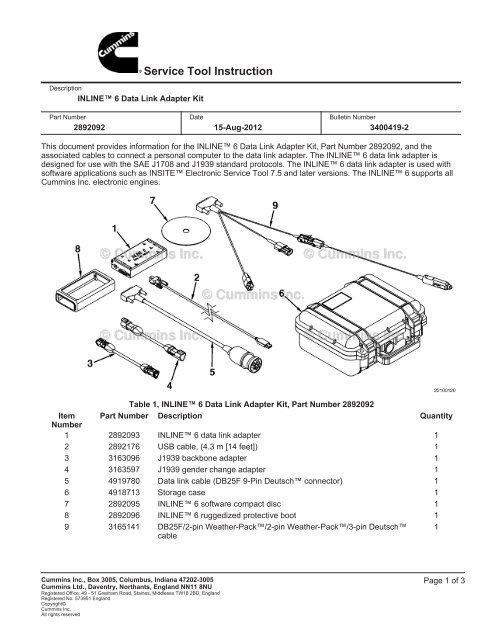
This document provides information for the INLINE 6 Data Link Adapter Kit, Part Number 2892092, and the<br />
associated cables to connect a personal computer to the data link adapter. The INLINE 6 data link adapter is<br />
designed for use with the SAE J1708 and J1939 standard protocols. The INLINE 6 data link adapter is used with<br />
software applications such as INSITE Electronic <strong>Service</strong> <strong>Tool</strong> 7.5 and later versions. The INLINE 6 supports all<br />
<strong>Cummins</strong> Inc. electronic engines.<br />
Table 1, INLINE 6 Data Link Adapter Kit, Part Number 2892092<br />
Item<br />
Number<br />
Part Number Description Quantity<br />
1 2892093 INLINE 6 data link adapter 1<br />
2 2892176 USB cable, (4.3 m [14 feet]) 1<br />
3 3163096 J1939 backbone adapter 1<br />
4 3163597 J1939 gender change adapter 1<br />
5 4919780 Data link cable (DB25F 9-Pin Deutsch connector) 1<br />
6 4918713 Storage case 1<br />
7 2892095 INLINE 6 software compact disc 1<br />
8 2892096 INLINE 6 ruggedized protective boot 1<br />
9 3165141 DB25F/2-pin Weather-Pack/2-pin Weather-Pack/3-pin Deutsch<br />
cable<br />
1<br />
<strong>Cummins</strong> Inc., Box 3005, Columbus, Indiana 47202-3005<br />
<strong>Cummins</strong> Ltd., Daventry, Northants, England NN11 8NU<br />
Registered Office: 49 - 51 Gresham Road, Staines, Middlesex TW18 2BD, England<br />
Registered No. 573951 England<br />
Copyright©<br />
<strong>Cummins</strong> Inc.<br />
All rights reserved<br />
Page 1 of 3
Page 2<br />
Table 2, Items Used with INLINE 6 Data Link Adapter Kit, Part Number 2892092, Purchased Separately<br />
Item<br />
Number<br />
Part Number Description Quantity<br />
Not Shown 4919797 DB25F/3-pin Deutsch/3-pin Deutsch/2-pin Weather-Pack cable 1<br />
Not Shown 3824440 DB25F 8-Pin AMP connector 1<br />
Not Shown 4918418 DB9F-DB9M serial cable 1<br />
Not Shown 3165160 DB25F/6-pin Deutsch cable 1<br />
NOTE: A fully populated USB cable, Part Number 2892176, or DB9F-DB9M, serial cable, Part Number 4918418,<br />
must be used.<br />
Connect the DB9F-DB9M serial cable, Part Number 4918418, or the USB cable, Part Number 2892176 to the RS-232<br />
serial port or the USB port of the computer and to the INLINE 6 data link adapter, Part Number 2892093.<br />
The INLINE 6 data link adapter requires +8-VDC to +50-VDC at 250mA that can be supplied through the OEM<br />
connector or by a separate power source.<br />
Connect the appropriate data link cable to the INLINE 6 data link adapter, Part Number 2892093.<br />
With the data link cable connected to the INLINE 6 data link adapter, connect the other end of the data link cable to<br />
the vehicle cab or engine compartment data link connector.<br />
Launch the electronic service tool application software.<br />
The following are the INLINE 6 Adapter Indicator Lamp Functions:<br />
Power Lamp<br />
• When the power lamp is lighted green continuously, this means DC power is being supplied to the adapter at the<br />
proper voltage level. The INLINE 6 adapter requires +8-VDC to +50-VDC at 250 mA that can be supplied<br />
through the OEM connector or by a separate power source.<br />
• When the power lamp is lighted red continuously, this means that either the INLINE 6 adapter is receiving a low<br />
power supply voltage (less than 8-VDC) or is only receiving power from the USB port.<br />
• When the power lamp is off, this means that the INLINE 6 is receiving no power.<br />
CAN 1 Port Lamp<br />
3400419-2<br />
• A CAN 1 red flashing lamp indicates that the INLINE 6 adapter is physically connected to a CAN data link.<br />
However, it is not communicating with an ECM on the CAN data link. A CAN 1 green flashing lamp indicates that<br />
the INLINE 6 adapter is communicating with an ECM on the CAN data link.
CAN 2 Port Lamp<br />
• A CAN 2 red flashing lamp indicates that the INLINE 6 adapter is physically connected to a CAN data link.<br />
However, it is not communicating with an ECM on the CAN data link. A CAN 2 green flashing lamp indicates that<br />
the INLINE 6 adapter is communicating with an ECM on the CAN data link.<br />
J1708 Port Lamp<br />
• A J1708 red flashing lamp indicates that the INLINE 6 adapter is physically connected to a J1708 data link.<br />
However, it is not communicating with an ECM on the J1708 data link. A J1708 green flashing lamp indicates that<br />
the INLINE 6 adapter is communicating with an ECM on the J1708 data link.<br />
RS-232 Port Lamp<br />
• An RS-232 green flashing lamp indicates that the INLINE 6 adapter is connected to an active RS-232 port and<br />
exchanging communications. An RS-232 lamp in the OFF state indicates that the INLINE 6 adapter is not<br />
communicating over the RS-232 port.<br />
USB Port Lamp<br />
3400419-2<br />
• A USB green flashing lamp indicates that the INLINE 6 adapter is connected to an active USB port and is<br />
exchanging communications. A USB lamp in the OFF state indicates that the INLINE 6 adapter is not<br />
communicating over the USB port.<br />
Page 3