turfcat 500 series - Golf Ventures
turfcat 500 series - Golf Ventures
turfcat 500 series - Golf Ventures

You also want an ePaper? Increase the reach of your titles
YUMPU automatically turns print PDFs into web optimized ePapers that Google loves.
ADJUSTMENTS 3<br />
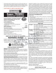
3.7 ENGINE BELT ____________________________________________________________<br />
Inspect and adjust new belt after first 50 hours of<br />
operation. Check and adjust annually thereafter.<br />
Adjust alternator pulley so belt deflects 1/4” to 5/16” (6 -8<br />
mm) with a 20 lb. push at midpoint between pulleys. See<br />
engine manual.<br />
A<br />
To adjust, loosen alternator mounting bolts (A) and adjust<br />
alternator until proper belt tension is achieved, then<br />
retighten bolts.<br />
TC023<br />
Figure 3F<br />
3.8 THROTTLE AND CHOKE ____________________________________________________<br />
Check throttle adjustment, if engine runs below<br />
recommended rpm with throttle lever in its high speed<br />
position. On tractors equipped with gas engines adjust<br />
choke control, if engine is hard to start.<br />
For other engine adjustments refer to the Engine<br />
Owner’s Manual supplied by the engine<br />
manufacturer.<br />
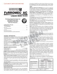
Gas engines<br />
1. Position throttle lever in its high speed position so<br />
that 1/16 - 1/4 in. (2-6 mm) gap exists between lever<br />
and panel. See E- Figure 3H.<br />
2. Pull up choke control on instrument panel to its<br />
choke position.<br />
3. Loosen cable casing clamp screw (A) on engine.<br />
4. Move throttle casing and wire (B) until throttle lever<br />
on engine touches high speed screw (C). Move<br />
choke cable and casing (D) until choke valve is<br />
completely closed<br />
5. Tighten casing clamp (A).<br />
A<br />
B<br />
Gas engine<br />
D<br />
C<br />
TC009<br />
Figure 3G<br />
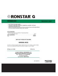
Diesel Engines<br />
1. Remove side cover from instrument panel.<br />
2. Position throttle lever in its high speed position so<br />
that 1/16 - 1/4 in. (2-6 mm) gap exists between lever<br />
and panel (E).<br />
3. With throttle lever on engine against max. speed<br />
stop, adjust throttle cable nuts (A) so that eyelet (B)<br />
on cable fits over on pin as shown.<br />
4. Install push nut so that eyelet slides freely when<br />
lever is rotated.<br />
B<br />
A<br />
E<br />
TC008<br />
Figure 3H<br />
11