Fiber - Fermilab
Fiber - Fermilab
Fiber - Fermilab

Create successful ePaper yourself
Turn your PDF publications into a flip-book with our unique Google optimized e-Paper software.
NOvA technology<br />
Jarek Nowak<br />
University of Minnesota
Argonne National Laboratory - University of Athens - California Institute of Technology - University of California, Los<br />
Angeles - Fermi National Accelerator Laboratory - Harvard University - Indiana University - Lebedev Physical Institute<br />
- Michigan State University - University of Minnesota, Duluth - University of Minnesota, Minneapolis - The Institute for<br />
Nuclear Research, Moscow - Technische Universität München, Munich - State University of New York, Stony Brook -<br />
Northwestern University - University of South Carolina, Columbia - Southern Methodist University - Stanford<br />
University - University of Tennessee - Texas A&M University - University of Texas, Austin - University of Texas, Dallas -<br />
Tufts University - University of Virginia, Charlottesville - The College of William and Mary - Wichita State University<br />
NOA: NuMI<br />
Off-Axis<br />
e<br />
Appearance Experiment<br />
Near detector<br />
protoblock<br />
180 Scientists and<br />
Engineers from 26<br />
Institutions
Project elements<br />
• <strong>Fiber</strong><br />
• Scintillator<br />
• PVC extrusions<br />
• Detector modules<br />
• Module assembly<br />
• Photodetector<br />
NOvA project<br />
NOvA – Totally Active Scintillator Detector<br />
Other important<br />
• Buildings<br />
• Software<br />
• Beam<br />
• Schedule to Data<br />
Taking<br />
• Electronics<br />
• Data Acquisition<br />
(DAQ)<br />
ANT2010, Santa Fe Jarek Nowak, September 17, 2010
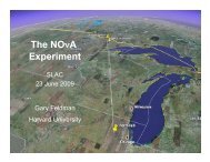
NOvA experiment<br />
• 2nd generation long baseline<br />
• Use existing high intensity beam of muon neutrinos at<br />
<strong>Fermilab</strong>.<br />
• Construct two detectors off the main axis of the<br />
beam.<br />
• Location reduces background for the search.<br />
• If neutrinos oscillate, electron neutrinos are observed<br />
at the Far Detector in Ash River, 810 km away.<br />
NOvA goals<br />
The atmospheric mass scale: Δm 2 32.<br />
Large mixing angle for atmospheric<br />
neutrino oscillations: θ 23.<br />
The third mixing angle: θ 13 .<br />
CP violation: δ CP .<br />
Mass ordering for the atmospheric<br />
oscillations: the sign of Δm 2 32.<br />
ANT2010, Santa Fe Jarek Nowak, September 17, 2010
1 blk - 78 modules<br />
1 H plane = 3 modules<br />
1V plane = 2 modules<br />
Near Detector<br />
209 T<br />
126 T totally active<br />
23 T fiducial<br />
2.9 m<br />
Near Detector prototype built on the<br />
surface in NUMI off-axis beam.<br />
Runs for ~1 yr<br />
Near detector put in the NUMI<br />
beam tunnel off axis.<br />
14.4 m<br />
4.1 m<br />
Shower<br />
containment<br />
Muon catcher<br />
1 m iron<br />
Target<br />
Veto<br />
3 H modules<br />
2 V modules<br />
ANT2010, Santa Fe Jarek Nowak, September 17, 2010
Near Detector m Catcher<br />
• The Near Detector is<br />
backed up by 1 meter of<br />
steel, with standard<br />
modules interleaved.<br />
• The m Catcher is now<br />
completely designed<br />
• Will be installed in the<br />
NDSB<br />
• Steel deliveries have<br />
delayed construction<br />
• 10 layers steel, module<br />
• Last layer has 4 modules<br />
ANT2010, Santa Fe<br />
Jarek Nowak, September 17, 2010
Far Detector<br />
1000 planes , 380,000 channels<br />
15 kT mass (~85% fudicial)<br />
• Cells are in 16-cell PVC extrusion.<br />
• Glue 2 extrusions together to make a 32 cell module.<br />
• 12 modules make up a plane.<br />
• Planes alternate horizontal and vertical.<br />
Extrusion cells in the<br />
near detector protoblock<br />
Simulated physicist<br />
ANT2010, Santa Fe Jarek Nowak, September 17, 2010
Detector Components<br />
• Liquid scintillator (3 million gallons)<br />
• Contained in 3.9cm x 6.6 cm cells of<br />
length 15.6 meters<br />
• 3.9 cm as seen by the beam<br />
• Cell walls are rigid PVC (5 kilotons)<br />
• Loaded with 15% anatase form of<br />
titanium dioxide<br />
• Diffuse reflection at walls keeps light<br />
near (within ~ 1 m) particle path<br />
• Looped wavelength-shifting fiber collects<br />
light (11,160 km)<br />
• <strong>Fiber</strong> diameter 0.7 mm<br />
• <strong>Fiber</strong> shifts wavelength to ~ 520-550 nm along the<br />
fiber<br />
• Avalanche photodiode (APD) converts light to electrical<br />
signal (11,160 devices, ea. 32 pixels)<br />
• 85% quantum efficiency<br />
typical<br />
charged<br />
particle<br />
path<br />
To 1 APD pixel<br />
ANT2010, Santa Fe Jarek Nowak, September 17, 2010<br />
W<br />
D<br />
L
Liquid Scintillator Composition<br />
• Liquid scintillator for NOνA is composed of a primary scintillant<br />
(pseudocumene) that gives off light at 300 nm,<br />
• waveshifters (PPO & bis-MSB) that downshift the UV photons to longer<br />
wavelength to facilitate absorption by the wavelength shifting (WLS)<br />
fibers (convert the photons to 420 nm),<br />
• anti-static agent (Stadis) that prevents the build-up of static electricity.<br />
• The “fluor mix” + anti-static are dissolved in a mineral oil solvent<br />
ANT2010, Santa Fe Jarek Nowak, September 17, 2010
WSL <strong>Fiber</strong><br />
Need ~ 12,000 km of 0.7 mm diameter wavelength<br />
shifting fiber from Kuraray. So far ~10% received<br />
and tested<br />
• MSU Quality Assurance Scanner (duplicate at Kuraray<br />
factory)<br />
• <strong>Fiber</strong> wound on a drum in a 27 m long groove with holes<br />
on 1 m intervals<br />
• <strong>Fiber</strong> is NOT cut from the spool,<br />
• Light source illuminates fiber from within the drum<br />
• Total light output (photodiode) and spectrographic scans,<br />
each ~ 1 minute<br />
K27 dye @ 300 ppm, S-type<br />
Michigan State
APD Description<br />
• APD is a classic linear APD manufactured by Hamamatsu<br />
operated at a gain (M) of 100<br />
• S11211(X) custom variant of commercial S8550<br />
SiAPD<br />
• Operating temperature is -15°C to keep shot noise at<br />
the same level as the amplifier noise<br />
• Signal-to-noise > 10 for muon at far end of a 15m long<br />
cell<br />
• Both ends of the fibers<br />
in each cell are read with<br />
a single APD<br />
• 32 APDs in a single<br />
4 8 array to readout<br />
one module<br />
Manufacturer<br />
Pixel Active Area<br />
Pixel Pitch<br />
Array Size<br />
Die Size<br />
1.95 mm × 1.0 mm<br />
2.65 mm<br />
32 pixels<br />
15.34mm × 13.64mm<br />
Quantum Efficiency (>525 nm) 85%<br />
Pixel Capacitance<br />
Bulk Dark Current (I B ) at 25 C<br />
Bulk Dark Current (I B ) at -15 C<br />
Peak Sensitivity<br />
Operating Voltage<br />
10 pF<br />
12.5 pA<br />
0.25 pA<br />
600 nm<br />
375 ± 50 volts<br />
Gain at Operating Voltage 100<br />
Operating Temperature (with<br />
Thermo-Electric Cooler)<br />
Expected Signal-to-Noise Ratio<br />
(Muon at Far End of Cell)<br />
-15 º C<br />
10:1<br />
APD channels per plane 384<br />
APD arrays per plane 12<br />
Total number of planes 930<br />
Total Number of APD arrays 11,160<br />
APD pixels total 357,120<br />
ANT2010, Santa Fe Jarek Nowak, September 17, 2010
Gain M<br />
Tests of APDs<br />
200<br />
180<br />
A1 A2 A3 A4 A5 A6 A7 A8<br />
B1 B2 B3 B4 B5 B6 B7 B8<br />
C1 C2 C3 C4 C5 C6 C7 C8<br />
D1 D2 D3 D4 D5 D6 D7 D8<br />
160<br />
140<br />
120<br />
100<br />
APD #14 @ -15 ºC<br />
M = 100<br />
80<br />
60<br />
40<br />
Gain vs. Bias Voltage<br />
20<br />
0<br />
0 20 40 60 80 100 120 140 160 180 200 220 240 260 280 300 320 340 360 380 400 420 440<br />
V<br />
450<br />
440<br />
APD #16<br />
APD #17<br />
APD #18<br />
APD #19<br />
Bias V drops ~0.8 V/ºC cooling<br />
430<br />
VR @ =100<br />
010, Santa Fe<br />
420<br />
410<br />
400<br />
390<br />
3.20E-03 3.30E-03 3.40E-03 3.50E-03 3.60E-03 3.70E-03 3.80E-03 3.90E-03 4.00E-03<br />
Inv. Temperature (K -1 )<br />
Gain=100 bias voltage linear vs. temperature<br />
• Measured average QE with RMS<br />
spread across 32 channels<br />
• Average across all channels (84.8<br />
± 2.5)% - expected 85%<br />
Jarek Nowak, September 17, 2010
APD tests<br />
Bias V for Gain = 100<br />
Average Dark Current<br />
• Bias voltage ~40 V lower at –15 ºC than +25 ºC<br />
• Batch 1 APDs bias voltage lower than batch 2<br />
• Average dark current ~20x lower at –15 ºC than +25 ºC<br />
• Batch 1 APDs average dark current ~10x lower than<br />
batch 2<br />
Dark current at room temp about 0.2na (40x better than specification)<br />
Jarek Nowak, September 17, 2010<br />
ANT2010, Santa Fe
REFLECTIVITY (%)<br />
PVC Extrusions<br />
15% Anatase titanium dioxide<br />
100<br />
90<br />
80<br />
70<br />
60<br />
50<br />
40<br />
30<br />
20<br />
10<br />
360 380 400 420 440 460 480 500<br />
ANT2010, Santa Fe<br />
Extrusion reflectivity as a<br />
function of wavelength reflectivity<br />
RSEX - OUTSIDE VS. INSIDE SURFACES<br />
27-5 REFERENCE IS THE AVERAGE OF 4 MEASUREMENTS<br />
POLYONE-3 OUT IS THE AVERAGE OF 6 MEASUREMENTS<br />
POLYONE-3 IN IS THE AVERAGE OF 18 MEASUREMENTS<br />
WAVELENGTH (nm)<br />
27-5 REFERENCE<br />
POLYONE-3 OUT<br />
POLYONE-3 IN<br />
• All NDOS extrusions<br />
produced.<br />
• Retooling for far<br />
detector extrusions<br />
(430 kg/hr)<br />
• Production started in<br />
August 2010<br />
Argonne & <strong>Fermilab</strong>
Technical details<br />
• N-27 PVC Resin Compounder Contract in Place<br />
• PolyOne Corporation (Different than R&D Vendor Aurora Plastics)<br />
• Material has been tested and meets NOvA specification<br />
• Extruding Vendor Contract in Place<br />
• Extrutech Plastics, Inc<br />
• Construction Dies and Tooling have been delivered<br />
• Tuning and testing since April<br />
• Expect die tuning to be completed in Sept. 2010<br />
• Dimensions: Optical Metrology Machine<br />
• Flatness, Thickness and Shape<br />
• Continuity of cell webs: Vacuum test<br />
• Alternate cells are placed under vacuum and others<br />
are at room pressure<br />
• Structural and Material Strength<br />
• Test short (6”) extruded samples<br />
• Hydraulic pressure test to failure ( ~150 psi )<br />
• Alternate cells pressurized<br />
• Drop-dart Impact test to measure of PVC ductility<br />
• Reflectivity: Spectrophotometer<br />
• Measures reflectivity across scintillation spectrum<br />
• MC computes relative light output of module<br />
ANT2010, Santa Fe
Module Architecture<br />
Side seals<br />
Center<br />
seal<br />
End plate<br />
Extrusion assembly
ND Manifold Architecture<br />
17<br />
Tom Chase, UMN<br />
Director's Review, August 4,<br />
2010
Raceway Functionality<br />
Face of optical<br />
connector<br />
• Registers fibers in optical<br />
connector<br />
• Guarantees acceptable<br />
bend radius<br />
• Shields fibers from events<br />
in manifold<br />
• Facilitates assembly<br />
18<br />
Threading fibers<br />
into opt conn
Production Factory<br />
A Huge warehouse for module production<br />
and storage for both extrusions and modules.<br />
Production is based on student labor.<br />
Far detector needs 24/day = 120/wk<br />
Production History for ND<br />
10/day<br />
Goal –<br />
6/day<br />
Moved to<br />
warehouse<br />
Final<br />
exams<br />
ANT2010, Santa Fe<br />
Jarek Nowak, September 17, 2010
Module Construction Process<br />
2 to 1 gluing<br />
preparation<br />
stringing<br />
threading flycutting Inner seal plasma prep<br />
ANT2010, Santa Fe<br />
Jarek Nowak, September 17, 2010
Module Construction Process<br />
Inner glue<br />
Inner seal<br />
Leak testing<br />
inner seal<br />
Outer seal<br />
Leak testing<br />
ANT2010, outer Santa seal Fe<br />
Painting<br />
Stacking & packing<br />
Jarek Nowak, September 17, 2010
Monitoring <strong>Fiber</strong> While Stringing<br />
• Monitors fiber tension and light<br />
transmission as cells are strung<br />
• Components<br />
• Light source<br />
• PVC tube with blue LEDs<br />
• Blinks at 10 Hz<br />
• Photodiode light sensor<br />
• Force meter<br />
<strong>Fiber</strong><br />
Roll<br />
<strong>Fiber</strong><br />
Light Source<br />
Clamp with<br />
Light sensor<br />
Good <strong>Fiber</strong><br />
Force meter<br />
Bad <strong>Fiber</strong><br />
John Kwong<br />
UMN<br />
Force meter<br />
Clamp with<br />
Light Sensor<br />
Defect<br />
ANT2010, Santa Fe Jarek Nowak, September 17, 2010
End-Lit <strong>Fiber</strong> Tester<br />
• Measures light transmission of threaded fibers<br />
• Bad fibers can be replaced (fibers not yet glued into optical<br />
connector)<br />
• Light is injected with blue laser and light is measured at the<br />
optical connector<br />
• Injection is highly localized and uniform across cells<br />
• Scan time = 40 seconds for 32 fibers<br />
• <strong>Fiber</strong> exposed to laser for ~0.5 seconds<br />
• Long exposure tests indicate no damage<br />
• Components<br />
• 10 mW blue laser<br />
• Robot that moves the laser<br />
• Photodiode light sensor<br />
• Hot wire fiber cutter<br />
Laser<br />
Bad <strong>Fiber</strong><br />
Light Sensor Cap<br />
ANT2010, Santa Fe Jarek Nowak, September 17, 2010<br />
Guide<br />
Rail
Types of Photos<br />
1 -Top Lit 2 - Bottom Lit 3 - Center Lit (normal angle)<br />
Top <strong>Fiber</strong><br />
Bottom <strong>Fiber</strong><br />
Shadow Cap<br />
Light In<br />
Transmitted<br />
Light<br />
Reflected<br />
Light<br />
Top <strong>Fiber</strong><br />
Bottom <strong>Fiber</strong><br />
Transmitted Light<br />
• Defects found by catching abnormal intensity of<br />
• Reflected light of angled light photos (1 & 2)<br />
• Transmitted light of angled light photos (1 & 2)<br />
• Light of normal angle light photo (3)<br />
Reflected<br />
Light<br />
Light In<br />
Top <strong>Fiber</strong><br />
Bottom <strong>Fiber</strong><br />
Transmitted and<br />
Reflected Light<br />
ANT2010, Santa Fe Jarek Nowak, September 17, 2010
Closed Module Tester<br />
• To be used for final QA at factory and<br />
after arrival at far detector site<br />
• Shine light on fiber ends and measure<br />
output intensity with a camera<br />
• Components<br />
• Digital camera<br />
• Three LED lights<br />
• Shadow cap<br />
Camera<br />
Lights<br />
Shadow Cap<br />
ANT2010, Santa Fe Jarek Nowak, September 17, 2010
Near Detector Assembly<br />
• Prototype Near Detector blocks have<br />
been assembled at ANL since April<br />
• Five blocks are at FNAL, in position.<br />
• Construction of the 6 th will begin soon.<br />
• Constructed at Argonne<br />
• Raised in the MINOS service building<br />
•The first mechanical prototype block<br />
(protoblock)<br />
• Partially assembled block (4 th of 6)<br />
Lowering the protoblock into<br />
the MINOS shaft at FNAL<br />
ANT2010, Santa Fe Jarek Nowak, September 17, 2010
Prototype Alignment<br />
Scanner maps surface,<br />
multiple measurements<br />
• One face of the protoblock, laser scanner test<br />
• This will be typical of the blocks - ~2.5 mm range<br />
• The contour of both faces track each other.<br />
ANT2010, Santa Fe<br />
Jarek Nowak, September 17, 2010
Summary<br />
• 5 out of 6 blocks of the Near Detector are installed.<br />
• The Integration Prototype Near Detector is extremely<br />
useful.<br />
• Filling with liquid scintillator will start within a few weeks.<br />
• The near detector will start taking data in November.<br />
• The far detector production is on the schedule.<br />
ANT2010, Santa Fe<br />
Jarek Nowak, September 17, 2010