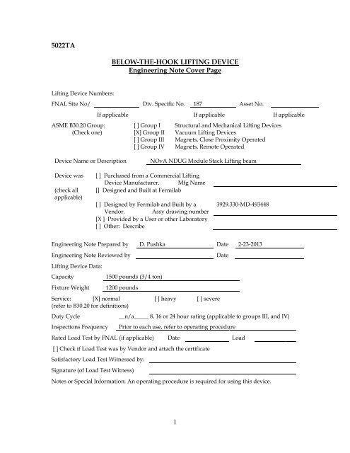
lifting fixture engineering note without reviewed by signature - NOVA ...
lifting fixture engineering note without reviewed by signature - NOVA ...
lifting fixture engineering note without reviewed by signature - NOVA ...

You also want an ePaper? Increase the reach of your titles
YUMPU automatically turns print PDFs into web optimized ePapers that Google loves.
Check Cantilevered Box Section Supporting the 8 small 5.5 inch diameterVacuum Cups:These cups are intended to be used for <strong>lifting</strong> the extrusion. However,there is not an apparent reason why they could not be mistakenly used for<strong>lifting</strong> the heavier steel plate. So, use the weight of the steel plate in thisanalysis as a conservative assumption:Consider the steel plate supported <strong>by</strong> 8 cups, each with the same load of1500/8 = 187 pounds.Design load,Span,Beam Material:Size:P = 187 poundsL = 16 inchesQty of box sections: Qty = 1A500 grade B carbon steel2” <strong>by</strong> 2” <strong>by</strong> 1/4” wall Squarestructural steel tubing.Allowable stress per ASME B30.20: σ allowable = F y /3 = 46,000 psi / 3=15,300 psiM max = P * L = 187.5 pounds * 16 inches = 3000 inch-poundsσ bending = M / S x = 3000 inch-pounds / 0.766 in^3 = 3916 psi.σ bending < σ allowable therefore, bending stress on the cantilevered box sectionbeam is okay.Check when safety catches are used, the length becomes 22 inches (52inches – 8 inches) / 2:M max = P * L = 187.5 pounds * 22 inches = 4125 inch-poundsσ bending = M / S x = 4125 inch-pounds / 0.766 in^3 = 5385 psi.σ bending < σ allowable therefore, bending stress on the cantilevered box sectionbeam is okay.8
Check Torsion due to the offset of the cups from the section centerline:Design load,Lever arm,Moment, T =J (in^4): 1.36.Radius, r (in) 0.694Torsion Stress, τ = T*r / J:P = 187 poundsL = 3 inchesT = 561 in-lbs286 psiτ actual
Consider the capacity of the small vacuum cups mistakenly used for thesteel plate (the round ones):Cup diameter:Cup Area:Cup Load:Cup load per unit area:5.5 inches23.75 square inches187 pounds7.87 psiVacuum system is designed for 14 psi vacuum and the UPC as defined <strong>by</strong>eqn 4-18 of BTH is:UPC = A * V p = Pad area * Vacuum at the padV p = 14 psiA = 23.75 square inchesUPC = 332 poundsMaximum vacuum pad rating is VPRVPR = UPC / N vN v = 2 + 2 sin thetaTheta = 0N v = 2VPR = UPC / N v = 332 /2 = 166 poundsConclusion: Using the 8 small cups to lift a steel plate exceeds theallowable load on these cups. So if a mistake is made and these cupsare used on the steel plate, the safety factor is reduced below thecode specified values.Image of the small, round vacuum cup intended to be used with theextrusions:10
Check Cantilevered “I” Section Supporting the 6 large 9 inch diameterVacuum Cups:These cups are intended to be used for <strong>lifting</strong> the steel plates:Consider the steel plate supported <strong>by</strong> 6 cups, each with the same load of1500/6 = 250 pounds.Design load,Span,Beam Material:Size:P = 250 poundsL = 8 inchesA36 carbon steelS3x5.7Qty of sections: Qty = 1Allowable stress per ASME B30.20: σ allowable = F y /3 = 36,000 psi / 3=12,000 psiM max = P * L = 250 pounds * 8 inches = 2000 inch-poundsσ bending = M / S x = 2000 inch-pounds / 1.68 in^3 = 1190 psi.σ bending < σ allowable therefore, bending stress on the cantilevered box sectionbeam is okay.Safety catches are not used on these members.End view of the I Section:11
Check Torsion due to the offset of the cups from the section centerline:Note, ASME BTH does not address this loading condition, because it isgenerally considered bad design to use an open section (angle, channel or Ibeam) in torsion; therefore the formula for this come from Roark andYoung – see section 10.7 in the 7 th edition which applies to wide flangesections. See table 10.2, case 6. For the boundary conditions, see table10.3, case 1a. The section used is a Standard section (S), but willapproximate using the Roark and Young formula):Design load, P =Lever arm, L =Applied torque, T 0 =Length of S section, l =Shear Modulus, G =250 pounds12 inches3000 in-lbs7 inchesJ (in^4): 0.04Radius, r (in) 1.23b = 2.33h = 3.011,500,000 psiE = 29,000,000t = 0.26t w = 0.17K =1/3 * (2*t 3 *b+t w 3 *h)K = 1/3 * (2*.26 3 *2.33+.17 3 *3.0)= 0.0322C w = h 2 * t *b 3 / 24= 3.0 2 * .26 *2.33 3 / 24= 1.23ß = (K*G / C w *E) 1/2= (0.0322*11,500,00/1.23*29,000,000) ½0.1019ß 2 = 0.010412
Θ max = T 0 * l / C w * E * ß 2Θ’ max = -T 0 / C w * E * ß 2Shear Stress, τ max =3000 * 7 / 1.23 * 29,000,000 *0.0104= 0.0567 radians= 3.24 degrees3000 / 1.23 * 29,000,000 *0.0104= - 0.0081t * G * Θ’ max0.26 * 11,500,000 * 0.008124,219 psiτ max > τ allowable therefore, torsional stress on the cantilevered “I”section due to the offset of the cup with respect to the box sectioncenterline is too high and represents a design error.Consider combined normal and shear stresses as addressed in section 3-2.5of ASME BTH:f cr = SQRT( f 2 x – f x *f y + f 2 y +3f 2 v ) < F cr = F yield /N df x = σ bending = 1190 psif y = 0f v = τ actual = 24,219 psif cr = SQRT( 1190 2 –0+ 0 +3*24,219 2 ) = psi41,965 >> 12,000 Therefore, this is not acceptable.Because the original design <strong>by</strong> Argonne does not meet ASME BTH, thefollowing few sections are added to address a modification to replace theS sections with box sections and meet the code.13
Check Cantilevered Box Section to Support the 6 large 9 inch diameterVacuum Cups:These cups are intended to be used for <strong>lifting</strong> the steel plates:Consider the steel plate supported <strong>by</strong> 6 cups, each with the same load of1500/6 = 250 pounds.Design load,Span,Beam Material:Size:P = 250 poundsL = 8 inchesQty of sections: Qty = 1S x 0.668 in 3A500 Box section carbon steel2 x 2 x 3/16 wall A500 Box sectionAllowable stress per ASME B30.20: σ allowable = F y /3 = 46,000 psi / 3=15,300 psiM max = P * L = 250 pounds * 8 inches = 2000 inch-poundsσ bending = M / S x = 2000 inch-pounds / 0.668 in 3 = 2994 psi.σ bending < σ allowable therefore, bending stress on the cantilevered box sectionbeam is okay.Check Torsion due to the offset of the cups from the section centerline:Design load,P = 250 poundsLever arm,L = 3 inchesMoment, T =T = 750 in-lbsJ (in 4 ): 1.15.Radius, r (in) 0.726Torsion Stress, τ = T*r / J: 473 psiτ actual
Consider combined normal and shear stresses as addressed in section 3-2.5of ASME BTH:f cr = SQRT( f x 2 – f x *f y + f y 2 +3f v 2 ) < F cr = F yield /N df x = σ bending = 2994 psif y = 0f v = τ actual = 473 psif cr = SQRT( 2994 2 –0+ 0 +3*473 2 ) = 3104 psi3104 < 46,000 / 2 Therefore, this is acceptable.Note that if safety catches were used for the steel plates and they wereinstalled at the ends of the 2 inch box sections, the resulting bending stresswould be:Design load,Span,P = 250 poundsL = 20 inchesM max = P * L = 250 pounds * 20 inches = 5000 inch-poundsσ bending = M / S x = 5000 inch-pounds / 0.668 in 3 = 7485 psi.σ bending < σ allowable therefore, bending stress on the cantilevered box sectionbeam is okay.So, for the steel plates, safety catches could be added and safely supported<strong>by</strong> these 2 inch box sections.15
New section added 3-20-2013 – Vendor failed to provide identical vacuumcups and so a new size will have to be ordered. This section addresses thecapacity of the new cups.Consider the capacity of the alternate vacuum cups used for the steelplate (the blue round ones) Anvar part number PS70S-NBR200 at $206each:Cup diameter:Cup Area:inchesCup rated Load:Cup load per unit area:Number of cups per compression plate section: 4Weight of a compression plate section:Weight per cup:7.13 inches39.92 square160 pounds4.0 psi326 pounds81.67 poundsVacuum system is designed for 14 psi vacuum and the UPC as defined <strong>by</strong>eqn 4-18 of BTH is:UPC = A * V p = Pad area * Vacuum at the padV p = 14 psiA = 39.92 square inchesUPC = 558 poundsMaximum vacuum pad rating is VPRVPR = UPC / N vN v = 2 + 2 sin thetaTheta = 0N v = 2VPR = UPC / N v = 558 /2 = 279 poundsConclusion: Using the 12 large cups to lift a steel plate is acceptableThe steel plate is made of three pieces, each 48 inches square <strong>by</strong> ½inch thick with 4 cups per plate piece (or section).16
Consider the capacity of the large vacuum cups used for the steel plate(the blue round ones) PS90S-NBR200 at $195 each:Cup diameter:Cup Area:Cup Load:Cup load per unit area:9 inches63.6 square inches250 pounds3.92 psiVacuum system is designed for 14 psi vacuum and the UPC as defined <strong>by</strong>eqn 4-18 of BTH is:UPC = A * V p = Pad area * Vacuum at the padV p = 14 psiA = 63.6 square inchesUPC = 890 poundsMaximum vacuum pad rating is VPRVPR = UPC / N vN v = 2 + 2 sin thetaTheta = 0N v = 2VPR = UPC / N v = 890 /2 = 445 poundsConclusion: Using the 6 large cups to lift a steel plate is acceptableHowever, the steel plate is made of three pieces, each 48 inchessquare <strong>by</strong> ½ inch thick. Original design used two cups for eachcompression plate section. Ideally, three or four cups should be usedwith each plate to reduce the rotation of the compression plate dueto differences between the plate center of gravity with respect toline drawn between only two cups.If only two cups remain used per compression plate, a means todetermine the maximum rotation of each compression plate isneeded so that the cup rating can be de-rated per ASME BTH section4-10. This is not possible as one cannot predict the maximum offsetthat a technician may inadvertently apply. So, use four cups perplate, this puts the center of gravity of the plate between the cups.17
Therefore the plate rotation is near zero and the de-rating factor forthe rotation angle theta in section 4-10 is negligible. Loadscalculated above are reduced <strong>by</strong> a factor of two and remainacceptable.Image of the large, round vacuum cup intended to be used with thesteel plates:These cups have a model or part number clearly shown on them:Comparing these to the Anver vacuum catalog (see:http://www.anver.com/document/vacuum%20components/vacuum%20cups/suspensions.htm ) these appear to be a ball mount, swivelsuspension with a part number of PS90S-NBR200 and the vacuumcup is a part number VP90-4.Vendor rated load for this cup and swivel mount assembly is 270pounds.18
The center lug (shown above) is part of the commercial vacuum <strong>lifting</strong>device and so calculations to show conformance with the BTH code areomitted from this document.Manufacture’s published literature indicates the capacity of this Vack Packis 10,000 pounds. See:http://www.anver.com/document/vacuum%20components/vacuum%20generators/vpf3_vacpack.htm19
Bolts connecting the commercial portion of the <strong>fixture</strong> to the box beam:A total of eight bolts attach the commercial vacuum <strong>lifting</strong> device AnverVack Pack to the weldment. These bolts are 3/8 inch diameter and areloaded in shear. Check the bolt shear.Total load is conservatively the weight of the <strong>fixture</strong> (1200 pounds) plus theweight of the <strong>fixture</strong> capacity (1500 pounds) less the weight of the VackPack (247 pounds):P =1200 + 1500 -247 = 2453 poundsBolts appear to be grade 8 socket head cap screws with a minimum tensilestrength of 120,000 psi.From ASME BTH section 3-3.2, the allowable shear stress is:F v =F v allowable =0.62 * F u / 1.20 * N d0.62 * 120,000 / 1.20 * 2.0 = 31,000 psi20
It is not clear if the shear plane passes thru the bolt shank or passesthru the threaded portion. Therefore, assume the shear plane goesthru the threaded portion and uses the root area.A = 0.0678 in 2Number of bolts = 8F v actual =F v actual
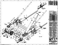
Documentation drawing for As Received condition of Lifting Fixture with IDnumber 187:A PDF of this drawing is available at: http://wwwadmscad.fnal.gov/MSDMain/cgi-bin/TP_PPDifind-web.plOnce this page is opened, type in the last six digits of the drawing number(493448) in the search box to access this drawing.22