NuMi Off-Axis Neutrino Appearance - NOVA Document Database ...
NuMi Off-Axis Neutrino Appearance - NOVA Document Database ...
NuMi Off-Axis Neutrino Appearance - NOVA Document Database ...

You also want an ePaper? Increase the reach of your titles
YUMPU automatically turns print PDFs into web optimized ePapers that Google loves.
Department of Energy<br />
Review Committee Report<br />
on the<br />
review of<br />
<strong>NuMi</strong> <strong>Off</strong>-<strong>Axis</strong><br />
<strong>Neutrino</strong> <strong>Appearance</strong><br />
(NOνA) Experiment<br />
April 2006
EXECUTIVE SUMMARY<br />
On April 4-6, 2006, a Department of Energy (DOE) Review Committee conducted a<br />
review of the <strong>Neutrino</strong>s at the Main Injector (NuMI) <strong>Off</strong>-<strong>Axis</strong> ν e <strong>Appearance</strong> Experiment<br />
(NOνA) Project at Fermi National Accelerator Laboratory (Fermilab). By the request of<br />
Dr. Robin Staffin, Associate Director for the <strong>Off</strong>ice of High Energy Physics (HEP), the Review<br />
Committee was chaired by Daniel Lehman, Director of the <strong>Off</strong>ice of Project Assessment. The<br />
purpose of the review was to validate the conceptual design and the cost range, which are needed<br />
for Critical Decision (CD)-1, Approval of Alternative Selection and Cost Range.<br />
The Committee was asked to verify that the conceptual design of the project adequately<br />
addressed the technical requirements; that the estimated cost and schedule ranges were<br />
reasonable; and that there was a team capable of managing the project to a successful<br />
completion. The Review Committee was comprised of 16 technical and management experts<br />
from DOE national laboratories, DOE headquarters, and U.S. universities.<br />
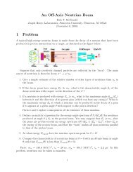
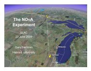
The NOνA project proposes to utilize the existing NuMI beamline and construct two<br />
new detectors optimized to detect electron neutrino interactions in order to observe the<br />
oscillation of muon neutrinos into the electron neutrinos and measure the parameters of that<br />
oscillation. One detector would be located on the Fermilab site and one would be<br />
approximately 800 kilometers away on a site to be determined in northern Minnesota.<br />
Overall, the Committee judged that the project is ready for CD-1. The Conceptual<br />
Design Report is complete and comprehensive. The cost and schedule ranges are appropriate.<br />
The Committee was impressed with the competence, depth of knowledge, and extensive<br />
experience of the scintillator team in performing physics experiments with liquid scintillator<br />
(LS) and wavelength-shifting fibers (WLSF). The conceptual designs for the WLSF and the LS<br />
are much more thorough and detailed than are required for CD-1.<br />
The Committee commended the project’s progress on Poly Vinyl Chloride (PVC)<br />
modules and their approach to PVC extrusion procurement. Exceptional progress has been made<br />
on the Far Detector assembly planning. The Near Detector is not as well advanced, but is<br />
adequate for CD-1. Electronics and data acquisition have an experienced team and detailed<br />
design is available for most components.<br />
i
The project team has developed a conceptual design for the site and building at the<br />
proposed Ash River site. The site was selected as the best of five proposed sites. Preliminary<br />
borings have been completed at the site and additional geotechnical borings are planned. The<br />
proposed building conceptual design meets the technical performance requirements to enable<br />
installation and operation of the NOνA detector.<br />
An Architect/Engineer (AE) will be used to evaluate the schedule and prepare an<br />
independent cost estimate. Additionally, the AE will be used to prepare the 30 percent design<br />
package. The schedule illustrates the 30 percent design starting in October 2006, with<br />
completion by January 2007.<br />
DOE plans to solicit proposals for a cooperative agreement with a third party to manage<br />
the design build contract for the facility and later the operations of the facility.<br />
The Committee found the cost estimate to be well-advanced for this stage of the project.<br />
The Total Project Cost range of $197-$256 million is reasonable. The range could be used as a<br />
basis for requesting CD-1, if supported by an appropriate funding profile. The project is using<br />
an acceptable methodology of contingency. Assessment is reasonable in most areas.<br />
The Committee found the 50-month schedule for a 25kT detector to be reasonable at this<br />
stage of the project.<br />
The proposed cooperative agreement for the building site and construction appears to be<br />
on the project critical path. Exact site and acquisition strategy will be needed at CD-2, Approve<br />
Performance Baseline. The adequacy of R&D—PED (Project Engineering and Development)<br />
funding is dependent on resolution of acquisition strategy. A firm funding profile for the project<br />
has not been established.<br />
NOνA management and staff vocalize and demonstrate support of Integrated Safety<br />
Management functions and principles. The Environmental Safety and Health aspects of NOνA<br />
have been adequately addressed for this stage of the project.<br />
A NOνA Project Management team is in place and functioning well. The documents<br />
needed to complete the CD-1 process have been identified—most of the documents have been<br />
completed. The remainder of the documents are in final draft status and require input from HEP<br />
and the Fermilab Site <strong>Off</strong>ice (FSO).<br />
ii
The Project Management team has a clear timeline for Critical Decisions (e.g., CD-2) and<br />
the related reviews.<br />
There were no action items resulting from the review.<br />
iii
CONTENTS<br />
Executive Summary............................................................................................................. i<br />
1. Introduction....................................................................................................................1<br />
2. Technical........................................................................................................................3<br />
2.1 Scintillator and Fiber ...............................................................................................3<br />
2.2 Mechanical and Assembly .......................................................................................4<br />
2.3 Trigger and Data Acquisition ................................................................................13<br />
3. Conventional Facilities ................................................................................................19<br />
4. Cost Estimate ...............................................................................................................21<br />
5. Schedule and Funding..................................................................................................25<br />
6. Environment, Safety and Health..................................................................................27<br />
7. Procurement .................................................................................................................29<br />
8. Management.................................................................................................................31<br />
Appendices<br />
A. Charge Memorandum<br />
B. Review Participants<br />
C. Review Agenda<br />
D. Contingency Table
1. INTRODUCTION<br />
The <strong>Neutrino</strong>s at the Main Injector (NuMI) <strong>Off</strong>-<strong>Axis</strong> Electron <strong>Neutrino</strong> <strong>Appearance</strong><br />
(NOνA) Experiment is a proposed alternative being considered for the Electron <strong>Neutrino</strong><br />
<strong>Appearance</strong> (EνA) project. The Department of Energy (DOE), Director of the <strong>Off</strong>ice of Science<br />
(SC), Raymond Orbach, approved Critical Decision (CD) 0, Approve Mission Need, for EνA on<br />
November 25, 2005. The NOνA proposal utilizes the world’s most intense neutrino beam, the<br />
NuMI neutrino beam at Fermi National Accelerator Laboratory (Fermilab) and will create a new<br />
large (20-30 kiloton) neutrino detector that is optimized for the detection of electron neutrinos.<br />
The <strong>Off</strong>ice of High Energy Physics (HEP) requested that the <strong>Off</strong>ice of Project Assessment<br />
conduct a review of the project in preparation for CD-1, Approve Alternative Selection and Cost<br />
Range. The review was held on April 4-6, 2006 and was chaired by Mr. Daniel Lehman. The<br />
purpose of the review was to verify that the project’s technical design adequately addressed the<br />
technical requirements, the estimated cost range was credible and sufficiently documented, and<br />
there was a team capable of completing the design of the detector and developing the technical,<br />
cost, and schedule baseline needed for CD-2, Approve Performance Baseline.<br />
The NOνA project consists of a Near Detector on the Fermilab site, a Far Detector<br />
located 700-800 kilometers (km) away in Northern Minnesota, and a detector hall for that<br />
detector.<br />
NOνA Far Detector: The NOνA Far Detector is optimized for detecting low-energy<br />
(approximately 2 GeV) electron showers while rejecting background events. High-signal<br />
efficiency and good background rejection require frequent sampling in materials with low atomic<br />
number.<br />
The Far Detector will be a 20,000-30,000-ton tracking calorimeter, measuring 15.7 by<br />
15.7 meters and more than 100-meters long. It is constructed from alternating vertical and<br />
horizontal cells of liquid scintillator (LS) contained in rigid plastic extrusion modules. A<br />
wavelength shifting fiber (WLSF) is inserted into each LS cell and terminates on a pixel of a<br />
32-pixel Avalanche Photo Diode (APD) chip. The APD is followed by front-end electronics that<br />
amplify, multiplex, digitize, and zero suppress signals before passing them to the data acquisition<br />
system.<br />
1
NOνA Near Detector: The NOνA Near Detector will operate on the Fermilab site at a<br />
distance of about 1 km from the NuMI target in the existing NuMI access tunnel. The purpose of<br />
the Near Detector is to measure backgrounds to ν e identification that will appear in the Far<br />
Detector. The NOνA Near and Far Detectors are nearly identical. The only significant<br />
differences are the size, the clock speed of the electronics, and the requirement that the Near<br />
Detector be mobile.<br />
Far Detector Hall: The NOνA project requires construction of a detector hall in Northern<br />
Minnesota to house the NOνA Far Detector. The building will also include adequate space and<br />
infrastructure to facilitate construction and operation of the Far Detector. Most of the Far<br />
Detector hall will sit below grade. The exposed sides and top of the hall will be covered with a<br />
three-meter overburden of dirt and rock to shield against cosmic rays.<br />
2
2. TECHNICAL<br />
2.1 Scintillator and Fiber<br />
2.1.1 Findings<br />
The Committee was impressed with the competence, depth of knowledge, and extensive<br />
experience of the scintillator team in performing physics experiments with LS and WLSF. This<br />
experience and expertise was obtained in previous, successful experiments, such as the Main<br />
Injector <strong>Neutrino</strong> Oscillation Search (MINOS), the <strong>Neutrino</strong>s at Tevatron experiment (NuTeV),<br />
and the Monopole Astrophysics and Cosmic Ray Observatory (MACRO). The proposed NOνA<br />
conceptual design for the LS and WLSF is a natural extension of this work.<br />
The conceptual designs are excellent and satisfy the NOνA performance requirements.<br />
In particular, the composition, preparation, and performance of the LS and WLSF have been well<br />
studied and researched. Also well understood are the blending of the LS components, the testing<br />
and quality control associated with each step in the blending procedures that lead to the final LS<br />
mixture, the transport of the LS to the far-detector site, and the loading of the detectors at the far<br />
and near sites.<br />
The scintillator team is properly addressing various environmental safety and health (ES&H)<br />
issues, such as fire prevention and prevention of LS release into the environment. The present cost<br />
and schedule estimates seem to be reasonable; the costs of several major components are based on<br />
quotations from oil and fiber vendors.<br />
2.1.2 Comments<br />
The conceptual designs for the WLSF and especially for the LS are meticulous and<br />
detailed more than what is required for CD-1. Nevertheless, further R&D is required over the<br />
next year to finalize the specifications for the WLSF. The WLSF delivery schedule is on the<br />
critical path and the cost of the WLSF has increased significantly in recent months. It is prudent<br />
to explore proposals from more than one vendor.<br />
For future CD-2/CD-3, Approve Start of Construction, reviews, it will be important to<br />
complete the following actions:<br />
3
1. Perform aging tests on prototype extrusion cells with LS and WLSF, as soon as the<br />
specifications for all materials are finalized, to ensure compatibility.<br />
2. Periodically check the light output and attenuation length of archival LS and WLSF<br />
samples as a function of time. Ensure that the light output and attenuation length will<br />
not change with time, especially if the data were to indicate any deterioration in the<br />
properties of the LS and/or WLSF.<br />
3. Determine plans for clean-up of oil spills of a few gallons or more at the Near and Far<br />
Detector sites and at each location where the LS is being handled and blended,<br />
including the transport and transfer of the organic liquids.<br />
2.1.3 Recommendation<br />
1. The Committee recommends approval of CD-1.<br />
2.2 Mechanical and Assembly<br />
2.2.1 Findings<br />
PVC Extrusions<br />
The mechanical group has developed a robust design for the modules and overall<br />
detector, with a strong development and prototyping program.<br />
The design of the extrusions and module block assemblies shows good communication<br />
and optimization among the analysis, design, and integration groups. The extrusion design and<br />
preliminary assembly plans are structurally clean designs, and the test and prototype plans<br />
presented are intended to work down the open materials and structural design technical risks<br />
before CD-2.<br />
The prototyping and testing of the Poly Vinyl Chloride (PVC) resin mix has been<br />
commendable. The project has investigated many material mixes to optimize reflectivity and<br />
cleanliness while ensuring high quality and well-controlled processes. The candidate mixes of<br />
PVC do not appear to put stringent process control requirements on the extruder. This should<br />
keep the yield and quality high, once the process is finalized by the extruder. This is important<br />
to ensure controlled processes and smooth extrusion contracts.<br />
4
Panels are extruded at a rate of 1000 lbs/hr, which is about one vertical panel per hour.<br />
Typical tolerances are +/- 0.25 mm or larger. No extruder is currently set up to extrude the 52-<br />
inch width needed for NOνA modules, but the equipment is available and two companies are<br />
prepared to add the infrastructure to one of their lines. While this is a large job, it does not<br />
particularly tax the capability of either of the companies under contract. One extruder, in<br />
particular, has been supportive of the R&D effort.<br />
The feasibility of 16-cell modules was investigated, to remediate any 32-cell unit<br />
production problems. The 16-cell extrusions are within the current capabilities of many<br />
manufacturers. The biggest potential problem is the assembly manpower and flow, and how to<br />
integrate the electronics. The project is looking at options if this needs to be implemented, but<br />
do not have any indication that this will be a problem.<br />
An epoxy joint thickness test program is under way, to investigate the impacts of<br />
0.1 to 2.0 mm bondline thickness at the module-to-module face joints. This is an important test<br />
program to complete, since the results may affect the needed/allowed tolerances of extrusions<br />
and mating parts. Epoxy is applied to the bottom with a roll-coater. Module extrusions are<br />
shown to be flat enough to ensure a maximum bond line of 0.010. As a remediation, weights can<br />
be added on the top and/or add beads to ensure a minimum bond thickness.<br />
PVC Modules<br />
The module construction team presented the current status of the module design and<br />
plans for the module assembly process at three factories, two universities (The University of<br />
Minnesota and Michigan State University) and one at Fermilab or Argonne National Laboratory.<br />
The module consists of the PVC tube extrusion, the machined-out bottom seal plate and a<br />
multi-extrusion manifold that provides a protected path for the WLSF from the scintillator cell to<br />
the photodiode detector mounting block, as well as an attachment point for the oil fill and<br />
overflow system. Progress was made on the engineering design of the manifold components,<br />
relying on experience gained in the design and construction of the MINOS plastic scintillator<br />
detector modules for the manifold design. Finalization of the bottom plate design can occur only<br />
after trial assembly of modules with the 16-cell prototype tube extrusions, which will be<br />
available summer 2006. The plate will be machined at Fermilab. The team expects that this will<br />
have a lower cost than injection molding, which surprised the Committee. Quotes for both<br />
production processes should be available for the CD-2 review.<br />
5
The team has a well-planned process for identifying and evaluating the properties of glue that<br />
will be used to fasten the bottom plate and manifold.<br />
Module assembly time-and-motion studies are well advanced for this stage of the project.<br />
More complete and detailed planning is needed for CD-2, and much of the prototyping effort<br />
scheduled for this summer will allow evaluation of the details for final design and production.<br />
The plan for each of the three factory sites is to have a three cell assembly area with<br />
crane rails spanning the area. Two bridge cranes with manual trolleys will be shared among the<br />
three cells. These cranes will be used to move the 15.7-meter long, 1.3-meter wide, 32-cell<br />
modules across the bay for the stages of assembly. Each of the (approximately) 21,000 modules<br />
will be moved at least twice.<br />
The assembly process will take place on “tables” within each assembly cell. The tables<br />
need to be low to accommodate movement of modules by the crane within the bay. Module<br />
extrusions will be checked for shipping damage on receipt from the extruder. The WLSF will be<br />
batch sampled for quality. In the module assembly process, the WLSF loop will be drawn with a<br />
vacuum device from one end of the tube to the other using a “puck”. The fiber will be looped<br />
around the puck. The bend radius of the fiber imposed by the dimensions of the tube is<br />
somewhat tighter than the fiber manufacturer’s minimum suggested bend radius. After fiber<br />
stringing, parts of the manifold will be set in place. The fiber ends at the manifold end of the<br />
module will be routed to the photodiode interface plate. The continuity and mapping of the<br />
installed fibers will be checked. The bottom plate and the manifold will be glued in place. The<br />
fibers in the interface plate will be faced off to accommodate the mounting of the photodiode.<br />
The completed module will be tested for leaks at an established sensitivity of .1 liter/year.<br />
Modules will be placed on specially designed pallets with incorporated lifters, moved into a<br />
truck and shipped to the site of the experiment.<br />
Near/Far Detector Assembly<br />
The Far Detector, which is 25kt and is 73 percent active, consists of 54 blocks, each of<br />
which is composed of 31 alternating vertical and horizontal planes. The task for the Far Detector<br />
Assembly team is to receive and ensure quality assurance (QA) for the 32-tube modules from the<br />
factories, the readout hardware, and the LS. Twelve of the modules are assembled into a plane<br />
on the elevated work surface provided by the block raiser. The modules of the next plane are<br />
covered with glue as they are passed through the commercial roller coater, and are assembled at<br />
right angles onto the preceding plane. This process is continued until layer 31 completes the<br />
6
lock; it is expected to take one week once the process has become routine. After a weekend for<br />
the glue to dry, the block is rotated vertically and moved into place separated by a thin spacer,<br />
which provides lateral stability from the preceding block. After several additional blocks are<br />
installed, the first block is filled with oil. The detector is outfitted with the avalanche photodiode<br />
(APD) readout module and electronics, cabling, power, and cooling.<br />
The structural engineering for the detector is well advanced. The number of planes in a<br />
block is set by the requirement that the safety factor against buckling be at least five, as well as the<br />
need to limit propagation of swelling after filling. Horizontal extrusions are supported by the<br />
vertical modules. The vertical extrusions have thicker walls than the horizontal extrusions to<br />
reduce adhesive shear stress. Two glues were identified, which meet the structural requirements;<br />
one of these is preferred for being more ES&H friendly. Seismic concerns were briefly discussed<br />
during the review. There were no issues here, since the areas in which the detectors will be<br />
installed are classified as zero. This significant design consideration should be mentioned in the<br />
Technical Design Report.<br />
Time-and-motion estimates for the assembly process are well developed, and include<br />
14 weeks to set up the equipment, 42 weeks to “ramp-up” to full crew operating at the full block<br />
production rate, 42 weeks at the rate of a block per week. The assembly endgame has 9 weeks for<br />
ramping down the crew size and production rate, 4 additional weeks to complete the fill, and 3<br />
weeks to complete outfitting.<br />
The block assembly includes lifting of the assembled PVC modules using a vacuum<br />
lifting device. Again, there is the potential for at least two times 21,000 lifting operations, and<br />
safety will require a high-quality inspection and maintenance plan for these lifting devices.<br />
Once the blocks are in place, the utilities will need to be connected. This aspect of the<br />
installation is not yet developed. The Committee envisioned issues with access, especially to the<br />
top of the block for connection to the vertical modules, although the sides were not addressed.<br />
Connection of the cables and filling hoses will impose stresses on the module composite<br />
components. Once in place, it will be very difficult, if not impossible, to repair or replace these<br />
parts. Proper strain relieving is necessary to protect the module integrity.<br />
The filling operations were described and appeared detailed. However, structural<br />
analysis indicated that the vertical modules are to be filled first, but evidence showed the<br />
horizontal modules being filled first. The proposed filling operation will free-fall the mineral oil<br />
scintillator the 15.7m height of the vertical modules. This may pose hazards from static<br />
electricity. Flammable liquid standards require that tanks have a tube going to the bottom of the<br />
7
tank for filling. Fill sensing was mentioned, but is not yet developed. Fill sensing is an<br />
important feature of the filling operation to prevent overfilling, over pressurization and spillage,<br />
and may present a challenge for a closed-loop filling system. The filling and the utilities<br />
installation both require a systems engineering effort to coordinate and address the installation<br />
and integration process.<br />
ES&H has received careful consideration. The assembly task involves operation of<br />
heavy equipment; movement of heavy object; working in high places; use of adhesives with<br />
fumes; and LS spills that need to be contained. The route to ES&H success is recognized to be<br />
worker training and certification, procedures, monitoring and personnel protection equipment, as<br />
well as monitoring from safety officers and involvement of management.<br />
The detector assembly task is responsible for overall detector integration. To support this<br />
activity, the team meets regularly with the other task managers; in particular, with the Far<br />
Detector site construction team.<br />
The Near Detector, which weighs 209 tons, has a geometry that is similar to that of the<br />
Far Detector to duplicate the response of the Far Detector. The detector must physically fit into<br />
the MINOS underground enclosure with only limited changes due to its shared use with existing<br />
detectors. The location deep underground in tight quarters adds a special ES&H burden; in<br />
particular, scintillator containment and its compatibility with life safety. An additional<br />
constraint is that the detector must move over a limited range in the access tunnel. The detector<br />
is segmented into parts that can be lowered down the existing shaft. These requirements lead to<br />
assembly out of seven and eight plane modules, each 2.9m x 4.1m, which are mounted in<br />
cradles. There are 24 of these modules. Finally, there is a muon catcher section unique to the<br />
detector that consists of ten steel plates, each with a module plane attached. The total length of<br />
this detector is 14.4m. The Integration Prototype Near Detector, which will be located in the<br />
MINOS Service Building at Fermilab, will be used as a test bed for the detector elements; in<br />
particular, those of the Near Detector.<br />
2.2.1 Comments<br />
The Committee commended the team’s approach to extrusion procurement in both the<br />
optimization of the resin for mechanical and reflective properties (with the help of a PVC expert)<br />
and engagement with vendors to develop extrusion production.<br />
8
The Committee suggested that the team:<br />
• Complete an evaluation of the tradeoffs between the choice of 16-cell versus 32-cell<br />
extrusions. It was expected that the 32-cell extrusion would lead to lower cost;<br />
however, the die costs for this extrusion are very high, and it was unclear that this<br />
cost would be offset by lower labor costs.<br />
• Give higher weight to PVC mixtures that are easier for the extruders to work with,<br />
that are consistent with acceptable physics performance, in order to maintain better<br />
process controls on the extrusion process.<br />
• Complete material properties testing in longitudinal and transverse directions to<br />
confirm PVC extrusion material anisotropy properties.<br />
• Use the 16-cell extrusions to develop the QA plan (needed for ultrasonic or weight<br />
inspection, and/or thickness measurements at the extrusion ends good enough?); and<br />
• In future revisions of the Conceptual Design Review (CDR), if any, add further detail<br />
on structural analysis, including margins, and methodology, as well as stress margins<br />
on minimum dimensions. The structural analyses are more advanced than the CDR<br />
would lead one to believe. The Committee heard that the structural analyses were<br />
completed for the worst case tolerances, and an adequate safety factor exists. This is<br />
very positive, and should be documented in the CDR to demonstrate the design is<br />
well advanced.<br />
The Committee noted that 1) the cost, cost basis, and contingency estimate and schedule<br />
appear reasonable, and 2) the task manager shows good connection to the schedule.<br />
The Committee commended the team for their effort and progress on the PVC Modules,<br />
and stated briefly that:<br />
• Labor estimates for module assembly appear to be lean.<br />
• Although 100 percent contingency on labor for assembly seems high, the time<br />
allotted for the tasks appear tight, so that the high contingency is justified.<br />
• Additional engineering effort should focus on module assembly time and motion<br />
studies.<br />
• The project should consider increasing the number of bridge cranes to one per<br />
assembly cell and include stops to limit trolley travel in each cell.<br />
• Scissor tables for module movement and assembly should be considered.<br />
• The project should make use of design tooling to clamp the end plug manifold and<br />
bottom plate to the extrusion during gluing.<br />
• The epoxy for vertical curing should be evaluated and defined.<br />
• The methodology for the cost estimate appears adequate.<br />
9
• The task manager illustrated high-quality connection to the schedules.<br />
• Manpower appears to be adequate to receive CD-2 approval. The project realizes the<br />
need to hire the first factory manager immediately.<br />
• Structural analysis support appears thin and the project should evaluate the<br />
engineering manpower profile between the R&D and production phases for<br />
continuity.<br />
Time and motion studies for some assembly steps were very well done, but are incomplete.<br />
The routing of the fiber into the manifold is advanced, as is the testing plans for the modules<br />
through their various phases of construction. A similarly thorough assessment for all phases of<br />
module assembly is needed for CD-2. The prototype effort scheduled for this summer should<br />
provide significant insight into the steps necessary to properly assemble and test functional<br />
modules. The prototyping effort should include time and motion definition as one of its<br />
objectives.<br />
Of concern during this review was the handling of the (approximately) 900-pound<br />
extrusion/module. Pushing and pulling these loads overhead on the manual trolley can pose<br />
ergonomic issues, since the loads are relatively high. This process is likely to be repeated at<br />
least twice for each of the (approximately) 21,000 modules. There may be strain related injuries<br />
to personnel due to starting and stopping movement of the half-ton of the module and the lifting<br />
fixture. There is also great potential for collision of the extrusion or lifting fixture with the crane<br />
support structure. Stops at the ends of each cell would eliminate the potential for this event. The<br />
Committee recommended stops and three cranes, for each cell.<br />
Using vacuum fixtures is an acceptable industrial material handling method. However,<br />
with (approximately) 21,000 modules each moved multiple times, special care must be taken of<br />
the vacuum fixtures. The extrusions do not have a uniformly flat surface across its entire width,<br />
owing to the grooves at the webs of the extrusion cells. Further, the vacuum fixtures do not<br />
provide a positive mechanical attachment that can withstand long-term use and abuse. Frequent,<br />
complete maintenance and inspection will be necessary to assure proper function and operation<br />
of the vacuum lifting devices and to minimize the potential for a material handling incident.<br />
The assembly process will primarily be done on “tables” within each assembly cell. The<br />
tables should be low to accommodate manual movement of the cranes, but may be too low to<br />
work on without ergonomic impact. The positioning of the extrusion for assembly should be<br />
evaluated for an ergonomically friendly position.<br />
10
The use of scissor tables or other devices may be useful to achieve proper positioning.<br />
The project proposes to use the WLS fiber at a bend radius smaller than the minimum<br />
recommended by the manufacturer. The manufacturer has been consulted by the team, and<br />
responded that the intended bend radius should be acceptable. However, the team should fully<br />
evaluate this use to assure the fiber integrity is maintained. Damage to the coating of the fiber<br />
will not be discovered until filling, which would cause significant work to repair, if in fact it<br />
could be repaired in situ. There is significant potential to cause further bending of the fiber<br />
during filling and during shipping. For this reason, additional effort is necessary for a “fiber<br />
retainer” alluded to during the breakout sessions. The Committee felt that the “fiber retainer” is<br />
necessary to maintain the maximum bend radius possible once installed in the extrusion. This<br />
retainer would be permanent (glued into position at the end of the tube). It may or may not be a<br />
part of the fiber installation tooling (hockey puck).<br />
The module will have a bottom plate and manifold glued to the ends to form the<br />
container for the LS. This step requires clamping these parts in place on the tube extrusion until<br />
the epoxy is cured. The pressure test of the modules requires some type of containment in the<br />
event of a failure of the end cap glue joints. Other fixtures for the installation of the fiber and<br />
electronics were also discussed extemporaneously. It may be possible to incorporate all<br />
functions into one device. This particular instance also emphasizes the need for stronger system<br />
engineering to bring together the needs of different groups into integrated devices and designs in<br />
order to reduce manpower, cost, and time.<br />
Though much documentation of analyses and investigations done by the team exists, this<br />
was not made known to this committee until the day before the review. For future reviews it<br />
would be useful to make these documents available to the reviewers earlier.<br />
The Committee also noted that:<br />
• Progress was made on the Far Detector. The Committee was impressed with the level<br />
of detail in design and assembly planning. The level of maturity is close to the CD-2<br />
level.<br />
• Additional work is needed in design of the interface between detector modules and<br />
detector utilities. This work depends on a better understanding of the interaction of<br />
platforms provided as part of the outfitting of the Far Detector building with the<br />
detector and its services.<br />
• Near Detector design did not seem as far advanced. Proportionately more effort is<br />
needed to receive CD-2 approval.<br />
11
• The cost estimate appears to be credible.<br />
• The installation schedule and manpower is well developed and credible.<br />
• The task manager illustrated high-quality ownership of the schedule.<br />
• The use of a consultant to assist in the evaluation of scintillator handling was an<br />
effective decision made by the team.<br />
The Committee suggested that the team: 1) evaluate the need for edge stiffeners;<br />
2) consider leasing a roll coating machine for prototype effort; 3) develop detailed procedures for<br />
filling the modules to assure proper process and sequence (there should be no confusion<br />
regarding filling order); and 4) complete the life safety evaluation, to include Near Detector<br />
containment.<br />
2.2.3 Recommendations<br />
1. Recommend CD-1 approval for the PVC Extrusion.<br />
2. Recommend CD-1 approval for the PVC Modules.<br />
3. Revisit the time and motion studies for module assembly using experience gained<br />
with 16-cell extrusions.<br />
4. Perform an ergonomic assessment for module assembly; in particular, the manual<br />
trolley crane movement.<br />
5. Develop a plan for use and maintenance of the vacuum lifters.<br />
6. Design the fiber retainer to maintain fiber bend radius for filling and during<br />
transportation.<br />
7. Recommend CD-1 approval.<br />
8. Develop designs for strain relief of utilities on modules.<br />
9. Develop designs for access to install utilities on the top and sides of modules blocks.<br />
10. Develop a plan for use and maintenance of the vacuum lifters.<br />
12
11. Reinforce the systems engineering team at the project management level for control<br />
of interfaces.<br />
12. Evaluate filling operations for static electricity hazards.<br />
13. Develop a more robust plan for sensing liquid level during detector filling.<br />
2.3 Trigger and Data Acquisition<br />
2.3.1 Findings<br />
The electronics system (Work Breakdown Schedule [WBS] 1.6 and 2.6) includes<br />
(approximately) 20,000 APD modules, and approximately 20,000 readout front-end electronics<br />
boards, cooling, and low- and high-voltage supplies including distribution system.<br />
Data Acquisition (DAQ), WBS 1.7 and 2.7 includes the DAQ software, the DAQ<br />
hardware comprising 324 data concentrators, (approximately) 20 Gigabit Ethernet switches and a<br />
computer farm with (approximately) 260 processors. Included in this project are cables, the slow<br />
control system, the online databases, and the integration effort.<br />
Electronics System<br />
The electronics system consists of (approximately) 20,000 copies of a 32-channel front-end<br />
electronics module. Each module contains one 32-pixel APD detector and one printed-circuit board<br />
comprising one 32-channel analog amplifier Application Specific Integrated Circuit (ASIC) with<br />
on-chip readout multiplexer, one four-channel analog-to-digital converter chip, and one<br />
control/readout Field Programmable Gate Array (FPGA) with high speed serial interface.<br />
Avalanche Photo Diode: The proposed device is a modified version of an existing<br />
Hamamatsu device. The modification is necessary mainly to accommodate two fiber ends for<br />
each pixel. Detectors for evaluation were ordered and are expected in summer 2006. The<br />
detectors will be bump-bonded on NOνA-supplied, printed-circuit boards by Hamamatsu.<br />
Subsequently, the remaining board components including cables are assembled. There are some<br />
concerns about the proximity of some bump-bonds to the detectors with an approximate 500V<br />
potential difference between them. This could be a leakage current path that may need to be<br />
addressed. Prototype electronics for evaluation should be available in summer 2006 well before<br />
the required CD-2. The module/detector integration and the fiber/APD alignment needs more<br />
13
detailed design work, but is not considered a large risk. The detector package includes a thermoelectric<br />
cooler whose reliability might be an issue. First estimates show that as many as three<br />
packages would have to be replaced every day. The devices are readily accessible, but<br />
accelerated tests are planned to understand the failure rate under the more benign NOνA<br />
operating conditions. The cooler is necessary to operate the APDs at -15 o C to achieve a signalto-noise<br />
ratio of 10:1.<br />
Front-End Board: This is a straight-forward board with a custom Integrated Circuit<br />
designed by Fermilab, a 12-bit ADC (Analog to Digital Converter) and an FPGA. The ASIC is<br />
based on an existing design that was adapted for NOνA. A first prototype was received and<br />
measurements are being performed. A second prototype iteration is in the project schedule in<br />
case modifications are required. The signals from the detector are continuously digitized and<br />
processed in the FPGA. Only signals above threshold are packaged with a time-stamp and<br />
channel identification and forwarded to the DAQ system. Data rates of
MB/sec—a prototype DCM is under development. A conceptual design exists for the Clock and<br />
Control system. The network switches and the processor farm are commercial products.<br />
The components of the readout and control software and the online databases will be<br />
developed in three releases—the first one is due at the end of 2007 in time for the IPND<br />
(Integrated Prototype Near Detector) test. The architecture and the functionality of the proposed<br />
system are adequate for NOνA and fulfill the requirements.<br />
The number of full-time employees (FTE) working on the DAQ software appears to be<br />
extremely low to be able to deliver the proposed system on schedule. It is estimated that the<br />
group needs at least one or two additional FTEs as soon as reasonably possible.<br />
General Findings<br />
A WBS to Level 6 was presented including a detailed Basis of Estimate work-book. The<br />
project is divided into two phases—R&D and construction. The R&D phase lasts through end of<br />
FY 2007 and the construction phase is estimated to about 2.5 years. No contingency is included<br />
for the R&D phase.<br />
R&D phase is estimated (in FY 2006 dollars) at $3.75 million (Electronics: $2.14 million<br />
and DAQ: $1.61 million) and the construction phase at $23 million (Electronics: $20.3 million<br />
and DAQ: $2.7 million). The electronics construction includes 47 percent contingency, the DAQ<br />
includes 23 percent contingency with only eight percent contingency assigned for DAQ software<br />
labor.<br />
Most of the design work will be completed in the R&D phase of the project with some of<br />
the DAQ software development continuing during the construction phase.<br />
Cost-drivers are the APDs and front-end board costs, as well as the readout infrastructure<br />
that includes the high- and low-voltage power supplies, cooling, and power distribution. All of<br />
these are largely supported by vendor quotes.<br />
With the exception of the DAQ software no labor profiles were presented.<br />
15
2.3.2 Comments<br />
The Electronics and DAQ individuals working on NOνA are very experienced and the<br />
technical challenges are considered to be well within the capabilities of the group.<br />
The designs presented for the front-end electronics and the DAQ system provide<br />
sufficient throughput and flexibility to meet the (scientific) requirements of the NOνA<br />
experiment. No technical hindrance was identified.<br />
The APDs are single-vendor sourced (Hamamatsu). However, this is not unusual for<br />
silicon detector devices for high energy physics and is not a high risk. Hamamatsu has already<br />
redesigned their APDs to fit the NOνA design. If another iteration is required due to NOνAdriven<br />
modifications, a new mask set (at a cost of about $200K) would be needed.<br />
The ASIC is not considered a technical risk, but could impact the schedule if additional<br />
iterations are required. However, this is not considered very likely since the performance and<br />
complexity seems to be well within the capabilities of the design team.<br />
The noise performance required appears achievable and digital processing can improve<br />
the result if required.<br />
In general, it unclear what are the reliability requirements for the 20,000 electronics<br />
packages are (i.e., How many packages can be non-functional before they need to be replaced?).<br />
The requirements should be provided by systems engineering. All electronics are accessible,<br />
thus it is a mainly a question of maintenance efforts.<br />
The high-voltage supplies can source currents up to 15 mA per channel. The safety<br />
measures required for inclusion in the design of the high-voltage distribution system needs<br />
clarification.<br />
For the Near Detector, the project should illustrate that the probability of over-lapping<br />
signals in a detector element is negligible or effort needs to be budgeted to modify the front-end<br />
electronics boards for the Near Detector.<br />
Electronics calibration also needs to be defined in more detail and related software<br />
should be included in the plan. The DAQ system provides sufficient throughput and flexibility<br />
to meet the requirements.<br />
16
Data flow control and synchronization; in particular, between the front-end boards and the<br />
DCMs, should be further developed by the time of CD-2.<br />
The schedule to deliver a functional DAQ system in time for the IPND test is very tight.<br />
A great deal of the software development for the DAQ system is scheduled to occur during the<br />
R&D phase. The Committee was concerned that the FTE estimates for this subproject was<br />
extremely low. If possible, an additional software engineer should be added to this effort soon.<br />
Responsibilities for database design and maintenance among the sub-projects should be<br />
clarified. As presented, the DAQ WBS does not provide (sufficient) support for the hardware<br />
databases that require remote access, special data entry hardware, etc. Until the project decides<br />
to use an open-source database management system, the license costs for a commercial product<br />
such as Oracle should be included. Given the importance of databases for quality control and<br />
QA, as well as general bookkeeping during the construction phase, the Committee recommended<br />
adding additional database expertise to the project.<br />
For slow-controls, the project is looking for additional collaborators, which should help<br />
to complete the design of the system in time for the CD-2 review.<br />
Only an initial concept exists for the data archival system at the NOνA site, as well as the<br />
connection to Fermilab. Provided the low-data rates, this is not considered a risk.<br />
In general, the information was well presented to the Committee. For the hardware<br />
projects, the estimated cost seemed very appropriate. For CD-2, the WBS might need another<br />
internal review to ensure that there are no oversights. The Committee recommended including<br />
columns for man-hours and resource information on the spread-sheet listing the cost.<br />
<strong>Off</strong>-project labor (e.g. physicists) is not included in the current WBS. Combined with the<br />
fact that for most sub-project labor, profiles were not available during the review. This made it<br />
difficult to assess if sufficient personnel were assigned to these projects. The Committee<br />
suggested making this information more readily available for future review.<br />
Overall, the presented schedule appears to be credible.<br />
17
2.3.3 Recommendations<br />
1. Include off-project labor (e.g. physicists) access to review the man-power resource<br />
estimates.<br />
2. Consider the suggested increase in software man-power to meet the presented<br />
schedule.<br />
3. The Committee recommends CD-1 approval.<br />
18
3. CONVENTIONAL FACILITIES<br />
3.1 Findings<br />
The project team developed a conceptual design for the site and building at the proposed<br />
Ash River site. The site was selected as the best of five proposed sites. Preliminary borings<br />
were completed at the site and additional geotechnical borings are planned.<br />
A bottoms-up estimate was prepared by the project team. The contingency was assigned<br />
using guidance from the DOE cost estimating guide. The schedule was developed by the project<br />
team but does not reflect the recent decision to use a design build contract strategy.<br />
An Architect/Engineer (AE) will be used to evaluate the schedule and prepare an<br />
independent cost estimate.<br />
Value Engineering studies were conducted for the roof structure and the aisle access.<br />
The AE will perform additional studies of the secondary containment and the cut and fill<br />
optimization.<br />
An AE will be used to prepare the 30 percent design package. The schedule shows the<br />
30 percent design starting in October 2006, with an expected completion in January 2007.<br />
DOE plans to award a cooperative agreement with a third-party to award and<br />
cooperatively manage the design build contract for the facility.<br />
The risk assessment was documented in the CDR.<br />
3.2 Comments<br />
Evaluation and selection of the preferred site (Ash River) and alternative site (Orr-Buyk)<br />
was based on a sound decision and information gathering process.<br />
The use of an AE to do an independent review of the conceptual design estimate and<br />
schedule is commendable. The schedule should be revised to reflect the proposed design build<br />
contracting method.<br />
19
The project should prepare a comprehensive risk assessment prior to CD-2.<br />
A contingency analysis should be completed based on identified project risks. A Monte<br />
Carlo analyses methodology should be used to evaluate the adequacy of the contingency.<br />
The 3-meter rock overburden on the Ash River building has a cost impact of $6-7 million<br />
on the cost of the facility. This should be evaluated in more detail to determine if a more cost<br />
effective alternative could be found.<br />
The proposed building conceptual design meets the technical performance requirements<br />
to enable installation and operation of the NOνA detector.<br />
The project CDR and supporting documents justify the proposed cost range and project<br />
duration.<br />
3.3 Recommendation<br />
1. Recommend approval of CD-1.<br />
20
4. COST ESTIMATE<br />
4.1 Findings<br />
The cost estimate for the NOνA construction project was developed using a<br />
comprehensive task oriented WBS summarized below:<br />
Table 4-1.<br />
NOνA Work Breakdown Structure<br />
WBS 2.1<br />
WBS 2.2<br />
WBS 2.3<br />
WBS 2.4<br />
WBS 2.5<br />
WBS 2.6<br />
WBS 2.7<br />
WBS 2.8<br />
WBS 2.9<br />
WBS 2.10<br />
Far Detector Site and Building<br />
Liquid Scintillator<br />
Wave-Length Shifting Fiber<br />
PVC Extrusions<br />
PVC Modules<br />
Electronics Modules<br />
Data Acquisition Strategy<br />
Near Detector Assembly<br />
Far Detector Assembly<br />
Project Management<br />
Included in the project’s Total Project Cost (TPC) was WBS 1.X, R&D and Project<br />
Engineering and Design (PED) estimates. The project team presented a TPC range between<br />
$197-256 million (actual year [AY]) for the NOνA project. The best estimate was $247 million<br />
(AY), which includes 35 percent (approximately $64 million) contingency.<br />
The project’s cost and schedule estimates were presented down to WBS Level 5 in most<br />
areas, with some areas to Level 8. Quotations and other pricing were compiled to establish a<br />
base cost in FY 2006 budget. The Project <strong>Off</strong>ice will centrally manage the project controls<br />
software (Open Plan and COBRA). A summary of the NOνA preliminary estimate of project<br />
costs is shown in Table 4-2.<br />
21
Table 4-2.<br />
NOνA Project Cost Breakdown (AY$ in Millions)<br />
WBS ITEMS Total Project<br />
Cost<br />
2.1 Far Detector Site and Building $39.7<br />
2.2 Liquid Scintillator $41.7<br />
2.3 WLS Fiber $26.2<br />
2.4 PVC Extrusions $47.8<br />
2.5 PVC Modules $15.4<br />
2.5 Electronics $21.8<br />
2.7 Data Acquisition $2.9<br />
2.8 Near Detector Assembly $1.7<br />
2.9 Far Detector Assembly $23.9<br />
2.10 Project Management $3.6<br />
Construction Subtotal $224.7<br />
PED $10.3<br />
Total TEC $235.0<br />
R&D $11.9<br />
Total Project Cost $246.9<br />
The project is currently seeking DOE approval for CD-1.<br />
The estimate includes appropriate labor rates, fringes, etc., for all institutions including<br />
Fermilab with respective overhead rates applied. Material costs include various burdening rates<br />
depending on the nature and size of the procurements. Open Plan is the software tool used to<br />
develop the project cost estimate.<br />
The project developed a bottoms-up contingency based on maturity of design using a<br />
consistent methodology for Materials and Services (M&S) and labor. The result was a<br />
contingency of (approximately) 35 percent with respect to the base cost estimate. The NOνA<br />
project has few systems but many repeatable components. In many cases, the project is dealing<br />
with known vendors and has obtained solid quotes. There are few parts that use new or<br />
unproven technologies. The conventional facilities (CF) WBS element has the lowest overall<br />
contingency at 23 percent next to project management at four percent. Less rigor was applied in<br />
developing the CF contingency estimate as compared to the methodology applied to other WBS<br />
elements. A detailed breakdown of contingency by WBS can be found in Appendix D.<br />
22
4.2 Comments<br />
The Committee found the cost estimate to be well-advanced for this stage of the project.<br />
The TPC range of $197-256 million (AY) is reasonable.<br />
The NOνA location and acquisition plan are not yet finalized—this provides the highest<br />
level of uncertainty for the project. The Integrated Project Team should work aggressively to<br />
finalize these decisions immediately. These key decisions will help to clarify uncertainties on<br />
the cost estimate and schedule (critical path) and should be given the highest priority. Allocation<br />
of contingency to the CF WBS should be evaluated with the same rigor as the other elements.<br />
Overall, the NOνA project is made up of a small number of systems and procurements.<br />
Areas of cost risk that require attention are:<br />
• Scintillator and PVC—Tied to volatile oil prices.<br />
• WLSF—Single vendor recently increased price to approximately 60 percent from<br />
earlier estimates. A quote is now available, but there remains currency and single<br />
vendor risks. Work is progress to solicit alternative vendors.<br />
• Site Improvements/Building—Design/Build strategy is proposed to ensure that the<br />
science requirements are clearly identified and confirmed with collaboration.<br />
• Integration—Emphasize early prototyping of the Near and Far Detectors to ensure<br />
defects (or value engineering) are identified early on.<br />
• Quality Control/<strong>Database</strong> Management—Many parts repeated up to 20,000 times.<br />
Additional staff, testing, and documentation may be required.<br />
• Spares to account for infant mortality (electronics) and breakage/defects to achieve<br />
CD-4.<br />
The project is using an effective methodology for contingency. Assessment is reasonable<br />
in most areas and should be repeated prior to CD-2, incorporating decisions on the site location,<br />
building, and acquisition strategy. The 100 percent contingency assessment on integration labor<br />
should be reviewed for accuracy.<br />
The detailed Basis of Estimate (BOE) was not fully documented. Although, it is not<br />
necessary for CD-1, a comprehensive BOE (with quotations and detailed estimates) is required<br />
for CD-2.<br />
Project <strong>Off</strong>ice staff currently have off-project responsibilities that may create a<br />
bottleneck in configuration control and management processes. Prior to CD-2, staffing should be<br />
reviewed to ensure key configuration and QA staffing needs are adequate.<br />
23
The Committee concluded that currently the NOνA cost estimate is within the range of<br />
costs provided in the draft Project Execution Plan and the range could be used as a basis for<br />
requesting CD-1, if supported by an appropriate funding profile.<br />
4.3 Recommendations<br />
1. Reassess contingency on the entire project after finalizing the conventional building<br />
acquisition strategy and siting.<br />
2. Use a TPC range of $197-256 million for requesting CD-1 approval.<br />
24
5. SCHEDULE and FUNDING<br />
5.1 Findings<br />
The integrated resource-loaded cost/schedule estimate for the NOνA project consists of<br />
(approximately) 3,500 schedule activities using the scheduling tool Open Plan. The project team<br />
presented a schedule range between 45-58 months for the NOνA project with a 25kT detector.<br />
The best estimate was 50 months. The project team has also identified a scope range between<br />
25kT and 34kT for a fixed TPC of $247 million (AY). Proposed DOE CD-4, Approve State of<br />
Construction, milestones were presented for each Level 2 subsystem.<br />
Sources of forward-funding outside of DOE/SC are being sought, namely from the<br />
University of Minnesota; however, to date no source can be considered firm. The NOνA<br />
management team is also actively seeking other additional funding sources outside of DOE.<br />
5.2 Comments<br />
The Committee found the 50-month schedule for a 25kT detector to be reasonable at this<br />
stage of the project. The schedule will dilate with changes to the mass scope. CD-4 dates and<br />
definitions for the project have been proposed at WBS Levels 1 and 2. The proposed DOE<br />
cooperative agreement for the building site and construction appears to be on the project critical<br />
path. Exact site and acquisition strategy will be needed at CD-2. Environmental and seasonal<br />
construction risks should be well defined prior to CD-2.<br />
Major material procurements are a key schedule risk. The project team is to be<br />
commended for confirming quotes and delivery dates/quantities to produce a credible schedule.<br />
All large procurements appear to be well advanced and delivery schedules tie in well with<br />
integration tasks.<br />
The Committee was not provided with FTE estimates or manpower profiles. Clear,<br />
supportable estimates on manpower will be needed at CD-2, which should include base program<br />
supported physicists. The project team should communicate their resource needs with the<br />
laboratory and collaboration management.<br />
Integration tasks are well developed and under capable management for CD-1. The<br />
schedule needs revisiting once the acquisition strategy is finalized. Schedule risks related to<br />
25
integration and assembly tasks should be well understood prior to CD-2.<br />
A rough “technically-limited” funding profile was derived by the project team from the AY<br />
cost and schedule loaded profile. Cumulative planned R&D and PED work in FY 2007 will<br />
inundate available funding (assuming this work is fully committed) and will leave no available<br />
funding contingency for solving problems or maintaining schedule. The adequacy of R&D/PED<br />
funding is also dependent on resolution of the acquisition strategy. The FY 2008 funding assumes<br />
construction funds that require CD-2 approval. Once a funding profile is established, the project<br />
team should review its resource-loaded schedule to ensure success on NOνA’s commitment to<br />
DOE.<br />
Table 5-1.<br />
NOvA DOE Proposed Funding Estimate (Escalated M$)<br />
AY$ Assumes a Profile From the NOvA Cost & Schedule in Open Plan<br />
5.3 Recommendations<br />
1. Develop FTE resource estimates for the NOνA project (including zero cost<br />
physicists) immediately and communicate the project’s needs throughout laboratory<br />
management and the NOνA collaboration.<br />
2. Recommend approval of CD-1.<br />
26
6. ENVIRONMENTAL SAFETY and HEALTH<br />
6.1 Findings and Comments<br />
The NOνA ES&H review addressed planning for construction and R&D Integrated<br />
Safety Management (ISM). NOνA management and staff vocalized and demonstrated support of<br />
ISM functions and principles. The ES&H aspects of NOνA are adequately addressed for this<br />
stage of the project.<br />
Since the primary construction activity, the Far Detector Laboratory is planned for a<br />
Minnesota site, a primary NOνA project environmental assessment will be conducted to satisfy<br />
the Minnesota state rules. The project is required to have an approved Environmental<br />
Assessment Worksheet (EAW) for Minnesota, and NOνA holds documentation stating that the<br />
University of Minnesota will be responsible for submitting the EAW as the responsible<br />
government unit (RGU). The EAW will meet DOE requirements for the Minnesota site. NOνA<br />
management anticipated the need for additional environmental assessments for NOνA LS<br />
blending activities performed onsite by Fermilab.<br />
NEPA documentation for the construction phase of the project was developed.<br />
The NOνA team drafted a Preliminary Hazard Analysis, (NuMI) <strong>Off</strong>-<strong>Axis</strong> ν e <strong>Appearance</strong><br />
Experiment Hazard Analysis <strong>Document</strong> on November 11, 2005. The document is substantial<br />
and the team anticipates updating the plan as the project tasks are finalized. For example, if<br />
NOνA LS blending activities are performed onsite by Fermilab, then a more complete discussion<br />
of blending hazards is warranted. When an epoxy system is selected, the occupational health<br />
impact of sensitization to the epoxy components should be included. The confined spaces safety<br />
considerations required for the project should also be discussed.<br />
The schedule for completion of ES&H documents before CD-2 is reasonable.<br />
6.2 Recommendations<br />
1. Include ES&H criteria in selection of mineral oil if a “mildly refined” mineral oil is<br />
considered.<br />
27
2. Determine the impact of DOE 10 CFR 851, Worker Safety and Health Program, on<br />
the project. The rule codifies, with enforcement, the DOE worker protection program<br />
and is effective February 2007.<br />
28
7. PROCUREMENT<br />
7.1 Findings<br />
The NOνA project procurement activity is estimated at $150 million (approximately<br />
70 percent of the TPC).<br />
There has been significant progress on procurement support for this stage of the project.<br />
Contracts are in place for: prototype 16-cell extrusions; 25,000 meters of WLSF; dual sourced<br />
mineral oil orders with options valued at $21 million; and wave shifter procurements with<br />
options, are ready for award when final technical evaluations are complete.<br />
Project management knowledge of cost drivers, schedule challenges, and technical issues<br />
surrounding procurement activity is exemplary and management is aggressively working these<br />
challenges in a proactive manner.<br />
NOνA management is involved with DOE in establishing critical milestones and controls<br />
for the collaborative agreement to support CF operations.<br />
Import duties and exchange rate information are addressed on significant foreign<br />
procurements, but require further refinement.<br />
7.2 Comments<br />
Project management is commended for efforts to obtain formal business prices to support<br />
cost estimates on key procurement activity. This reduces cost risks to the project and positions<br />
NOνA to provide DOE with credible cost information to support upcoming CD-2 requests.<br />
Procurement personnel are placing prototype and initial orders with cost escalation<br />
indexes and options for follow-on quantities.<br />
The project should formalize how potential exchange rate fluctuations in business<br />
practices are addressed.<br />
Import duty exemptions may be possible for the significant foreign procurements.<br />
29
7.3 Recommendations<br />
1. Pursue potential import duty exemptions on major foreign procurement activities in<br />
support of NOνA prior to finalizing and placing obligating business documents.<br />
2. Continue to ensure project personnel work closely with procurement personnel to<br />
quantify costs on major procurements prior to CD-2 submission.<br />
30
8. MANAGEMENT<br />
8.1 Findings<br />
The NOνA Collaboration and Project Management team have completed a CDR. The<br />
CDR has clearly stated physics requirements, as well as technical solutions that satisfy the<br />
physics requirements. Technical alternatives were explored and documented. Significant<br />
optimization of the proposed design was completed and is acceptable for the current state of the<br />
project.<br />
The NOνA team has estimated the cost range of the project to be $197-256 million (TPC<br />
in AY), with a best estimate of $247 million. The estimated schedule range is 45-58 months,<br />
with a best estimate of 50 months.<br />
A NOνA Project Management team is in place and functioning well. The documents<br />
needed to complete the CD-1 process were identified—most of the documents are complete.<br />
The remainder of these documents is in final draft status and require input from the DOE/HEP<br />
and the Fermilab Site <strong>Off</strong>ice (FSO). The Project Management team has a clear timeline for<br />
scheduled CDs (e.g., CD-2) and the related reviews.<br />
The Project Management team developed a detailed R&D plan that includes essential<br />
elements required to achieve a project baseline. The personnel (physicists and technical) and<br />
other resources required to complete the R&D and design needed to achieve a baseline were<br />
identified and are available. There is little contingency in the proposed R&D funding, but the<br />
scope of the Integration Prototype Near Detector could be reduced if funds were needed in other<br />
areas.<br />
Non-U.S. resources (e.g., from Italy) are being actively sought by NOνA managers and<br />
Fermilab management.<br />
8.2 Comments<br />
A firm funding profile for the project has not been established. Close interaction<br />
between HEP, NOνA management, and Fermilab management will be required to establish a<br />
profile in time to meet CD milestones.<br />
31
The design and construction of the far assembly building in Minnesota is on the critical<br />
path for the project. The DOE NOνA Program Manager and Project Director need to work<br />
expeditiously with the NOνA team to establish a mechanism to fund the design and construction<br />
of the far assembly building to meet the schedule for CDs and reviews, and the desired project<br />
schedule.<br />
Critical input from HEP and DOE/FSO is needed to complete the prerequisite<br />
CD-1 documents (Acquisition Strategy and the Preliminary Project Execution Plan). Some<br />
coordination with DOE is also required to begin the monthly reporting process in May 2006<br />
Project Assessment and Rating System (PARS). NOνA management should clarify the<br />
requirements for Risk Assessment, in particular for CD-2.<br />
The Project Manager recognizes that some additional resources, in the areas of monthly<br />
reporting and QA, need to be added to his team in the next few months. The project is actively<br />
seeking to add these resources.<br />
8.3 Recommendations<br />
1. CD-1 approval is recommended upon receipt of final documentation.<br />
2. Establish (DOE and NOνA) an overall project funding profile and a mechanism for<br />
the design and construction of the far assembly building to proceed to CD-2.<br />
32
APPENDIX A<br />
CHARGE<br />
MEMORANDUM
memorandum<br />
DATE: January 24, 2006<br />
REPLY TO<br />
ATTN OF:<br />
SUBJECT:<br />
SC-25<br />
Request to Conduct a CD-1 Review of the NOνA Project.<br />
TO:<br />
Daniel R. Lehman, Director, SC-1.3<br />
The NuMI <strong>Off</strong>-<strong>Axis</strong> <strong>Neutrino</strong> <strong>Appearance</strong> (NOνA) Experiment is one of the proposals for the<br />
Electron <strong>Neutrino</strong> <strong>Appearance</strong> (EνA) Detector. I would like to request that you conduct a CD-1<br />
Review of the NOνA proposal on April 4-6, 2006 at Fermi National Accelerator Laboratory. The<br />
purpose of this review is to validate the conceptual design and the cost range, which are needed for<br />
Critical Decision 1, Approval of Alternative Selection and Cost Range.<br />
The NOνA project proposes to utilize the existing NuMI beamline and construct two new detectors<br />
optimized to detect electron neutrino interactions in order to observe the oscillation of muon<br />
neutrinos into the electron neutrinos and measure the parameters of that oscillation. One detector<br />
would be located on the Fermilab site and one would be approximately 800 kilometers away in a site<br />
to be determined in northern Minnesota.<br />
In performance of a general assessment of progress, current status, and the identification of potential<br />
issues, the committee should address the following specific items:<br />
1. Does the conceptual design satisfy the performance requirements?<br />
2. Does the conceptual design report and supporting documentation adequately justify<br />
the stated cost range and project duration?<br />
3. Does the proposed project team have adequate management experience, design<br />
skills, and laboratory support to produce a credible technical, cost, and schedule<br />
baseline?<br />
4. Are ES&H aspects being properly addressed and are future plans sufficient given<br />
the projects current stage of development?<br />
5. Is the documentation required by DOE O 413.3 in order and ready for Approval of<br />
CD-1?<br />
Michael Procario is the program manager for the EνA Detector Project in this office and<br />
will serve as the <strong>Off</strong>ice of High Energy Physics (OHEP) contact person for this review.
We appreciate your assistance in this matter. As you know, these reviews plan an important role in<br />
our program. I look forward to receiving your Committee’s report. You are asked to submit a<br />
formal report to OHEP within in 60 days of the review.<br />
/signed/<br />
Robin Staffin<br />
Associate Director<br />
<strong>Off</strong>ice of High Energy Physics<br />
cc:<br />
Ray Orbach, SC-1<br />
James Decker, SC-2<br />
Joanna Livengood, SC-FSO<br />
Pier Oddone, FNAL<br />
Aesook Byon-Wagner, SC-25
APPENDIX B<br />
REVIEW<br />
PARTICIPANTS
Department of Energy Review of the NOνA Experiment at Fermilab<br />
REVIEW COMMITTEE PARTICIPANTS<br />
Daniel R. Lehman, Chairman (DOE)<br />
SC 1 SC 2 SC 3<br />
Mechanical Trigger and<br />
Scintillator and Assembly Data Acquisition<br />
* Bill Louis, LANL * Bill Wisniewski, SLAC * Klaus Honscheid, OSU<br />
Richard Hahn, BNL Steve Kane, BNL Gunther Haller, SLAC<br />
Martin Nordby, SLAC<br />
SC 4 SC 5 SC 6<br />
Civil Construction Cost, Schedule, and Funding Management<br />
* Jack Stellern, ORNL * Mark Reichanadter, SLAC * Murdock Gilchriese, LBNL<br />
Marty Fallier, BNL Rick Korynta, TJNAF Randy Ogle, ORNL<br />
Steve Tkaczyk, DOE/SC Barry Miller, Consultant<br />
[Mark Reichanadter, SLAC]<br />
Observers LEGEND<br />
Robin Staffin, SC-20 Steve Webster, DOE/FSO SC Subcommittee<br />
Aesook Byon-Wagner, SC-20 Ronald Lutha, DOE/FSO * Chairperson<br />
Michael Procario, SC-20 Joanna Livengood, DOE/FSO [ ] Part-time Subcom. Member<br />
Count: 17 (excluding observers)
APPENDIX C<br />
REVIEW<br />
AGENDA
Department of Energy Review of the<br />
NOνA Experiment at Fermilab<br />
AGENDA<br />
Tuesday. April 4, 2006—Wilson Hall Bldg.—Comitium<br />
8:00 am DOE Executive Session ...........................................................................D. Lehman<br />
9:00 am Welcome and Laboratory Overview—One West ................................... P. Oddone<br />
9:10 am Scientific Performance Requirements.............................G. Feldman/or M. Messier<br />
9:25 am Project Overview ....................................................................................... J. Cooper<br />
10:10 am Break<br />
10:40 am Project Cost Drivers.........................................................................R. Ray/R. Cibic<br />
10:55 am Site and Building ........................................................................................ S. Dixon<br />
11:20 am Scintillator.................................................................................................S. Mufson<br />
11:50 am Fiber ......................................................................................................C. Bromberg<br />
12:05 pm Lunch<br />
1:05 pm PVC and Extrusions...................................................................................R. Talaga<br />
1:25 pm Extrusion Modules......................................................................................K. Heller<br />
1:40 pm Electronics and DAQ ...............................................................................L. Mualem<br />
2:10 pm Near/Far Detector Assembly ....................................................................... D.Ayres<br />
2:40 pm Cost and Schedule Range .......................................................................... J. Cooper<br />
2:55 pm Cost and Schedule Methodology ...........................................................W. Freeman<br />
3:10 pm Break<br />
3:25 pm Subcommittee Breakout Sessions<br />
• Site and Building—Blackhole<br />
• Commodities—Scintillator, Fiber, and PVC—One North<br />
• Extrusion Module Production—Snakepit<br />
• Electronics and DAQ—Racetrack<br />
• Far and Near Detector Assembly—One East<br />
5:00 pm DOE Executive Session—Comitium......................................................D. Lehman<br />
6:00 pm Adjourn
Wednesday, April 5, 2006<br />
8:00 am Subcommittee Breakout Sessions<br />
• Site and Building—Blackhole<br />
• Commodities—Scintillator, Fiber, and PVC—One North<br />
• Extrusion Module Production—Snakepit<br />
• Electronics and DAQ—Racetrack<br />
• Far and Near Detector Assembly—One East<br />
• Management, Cost and Schedule—Comitium<br />
10:00 am Break<br />
10:15 am Subcommittee Breakout Sessions, Con’t<br />
12:00 pm Lunch<br />
1:00 pm Subcommittee Breakout/Working Session<br />
3:00 pm DOE Full Committee Executive Session—Comitium ...........................D. Lehman<br />
6:00 pm Adjourn<br />
Thursday, April 6, 2006<br />
8:00 am Subcommittee Working Sessions—1 North<br />
10:00 am DOE Full Committee Executive Session Dry Run—1 North.................D. Lehman<br />
12:00 pm Working Lunch<br />
2:00 pm DOE Summary and Closeout—One West..............................................D. Lehman<br />
3:00 pm Adjourn
APPENDIX D<br />
CONTINGENCY<br />
TABLE
NOνA Contingency Table<br />
April 4-6, 2006<br />
TEC<br />
Project Estimate AY $K<br />
To Date To Go Contingency<br />
Total<br />
WBS<br />
Items<br />
Cost Cost $ %<br />
2.1 Far Detector Site and Building $ - $ 32,199.8 $ 7,454.8 23% $ 39,654.6<br />
2.2 Liquid Scintillator $ - $ 32,016.1 $ 9,690.1 30% $ 41,706.2<br />
2.3 Wave-Length-Shifting Fiber $ - $ 20,466.3 $ 5,730.4 28% $ 26,196.7<br />
2.4 PVC Extrusions $ - $ 34,196.0 $ 13,653.0 40% $ 47,849.0<br />
2.5 PVC Modules $ - $ 9,848.8 $ 5,518.8 56% $ 15,367.6<br />
2.6 Electronics Production $ - $ 14,824.2 $ 6,993.4 47% $ 21,817.6<br />
2.7 Data Acquisition System $ - $ 2,352.9 $ 569.3 24% $ 2,922.1<br />
2.8 Near Detector Assembly $ - $ 835.1 $ 821.7 98% $ 1,656.8<br />
2.9 Far Detector Assembly $ - $ 12,803.1 $ 11,145.4 87% $ 23,948.5<br />
2.10 Project Management $ - $ 3,464.7 $ 119.5 3% $ 3,584.1<br />
Construction $ - $ 163,006.9 $ 61,696.3 38% $ 224,703.3<br />
PED Funded $ - $ 8,491.2 $ 1,808.8 21% $ 10,300.0<br />
Total TEC: $ - $ 171,498.1 $ 63,505.1 37% $ 235,003.2<br />
OPC<br />
R&D $ 1,043.2 $ 11,690.6 $ 186.3 2% $ 11,877.0<br />
Total OPC: $ 1,043.2 $ 11,690.6 $ 186.3 2% $ 11,877.0<br />
TPC: $ 1,043.2 $ 183,188.8 $ 63,691.4 35% $ 246,880.2