Design and Construction of Low Energy Houses in Saskatchewan
Design and Construction of Low Energy Houses in Saskatchewan
Design and Construction of Low Energy Houses in Saskatchewan
- No tags were found...

You also want an ePaper? Increase the reach of your titles
YUMPU automatically turns print PDFs into web optimized ePapers that Google loves.
DESIGN AND CONSTRUCTION<br />
OF LOW WERGY HOUSES IN SASKATCHEWAN<br />
by<br />
H, W. 6rr<br />
llivision <strong>of</strong> Build<strong>in</strong>g Research, National Research Council <strong>of</strong> Canada<br />
Ottawa, April 1982<br />
3C - C fsr;<br />
BLDG. R e<br />
LlBRARy
DESIGN AND CONSTRUCTION OF U3W ENERGY HOUSES IN SASKATCHEWAN<br />
by<br />
H.W. Orr<br />
As a result <strong>of</strong> the need t6 reduce energy use there has been an<br />
<strong>in</strong>terest on the part <strong>of</strong> government <strong>and</strong> some private <strong>in</strong>dividuals <strong>in</strong><br />
construct<strong>in</strong>g super-<strong>in</strong>sulated houses, sometimes called low energy<br />
houses. In these houses, thermal resistances <strong>of</strong> the walls <strong>and</strong><br />
ceil<strong>in</strong>g are typically RSI 7 (U 40) <strong>and</strong> RSI 10 (R 573, respectively;<br />
special efforts are usually made to keep air <strong>in</strong>filtration to a<br />
m<strong>in</strong>imum.<br />
It should be noted that these are unusual build<strong>in</strong>gs; only two<br />
or three hundred such houses have been built <strong>in</strong> Canada. Thus they<br />
represent a small fraction <strong>of</strong> one per cent <strong>of</strong> dwell<strong>in</strong>gs constructed<br />
<strong>in</strong> this eountqr <strong>in</strong> the past two or three years. Observation <strong>of</strong><br />
some <strong>of</strong> these houses <strong>in</strong>dicates that, wheli compared with conventional<br />
houses, significant reductions <strong>in</strong> energy consumption have been<br />
achieved. Cont<strong>in</strong>ued observation <strong>of</strong> their performance <strong>and</strong> documentation<br />
oE details <strong>of</strong> construction constitute an important contribution<br />
to the development <strong>of</strong> hous<strong>in</strong>g <strong>in</strong> Canada.<br />
This report provides some <strong>of</strong> the background <strong>of</strong> this development<br />
on the Prairies. It describes details <strong>of</strong> wall <strong>and</strong> foundation designs<br />
that have been used. It does not addres~ the ques~ibn however <strong>of</strong><br />
whether these dezails are justifiable from an economic st<strong>and</strong>pa<strong>in</strong>t.<br />
The dimensions <strong>of</strong> wall studs <strong>in</strong> houses are usually governed by<br />
structuxal needs. The amount af thermal <strong>in</strong>sulation required by<br />
current build<strong>in</strong>g regulations can be fitted <strong>in</strong>to the 89 m (3+-<strong>in</strong>.)<br />
wall space provided by 2 x 4 studs. This space, filled with<br />
-<br />
3<br />
24 kg/m m<strong>in</strong>eral wood, provides about RSI 2.1 (R 12) ; tak<strong>in</strong>g<br />
other wall components <strong>in</strong>to account produces RSI 2.5 (R 14.2).<br />
In the past feu years, several <strong>in</strong>novations <strong>in</strong> wall design have<br />
appeared which provide for greater thermal resistances. In some<br />
new houses, rigid <strong>in</strong>sulation, usually 38 mm (1-5 <strong>in</strong>.) thick, is<br />
applied outside <strong>of</strong> 38 x 89 m (2 x 43 wall studs. In some others,<br />
38 x 14C: m (2 x 6) studs are used. When filled with m<strong>in</strong>eral wool<br />
or equivalent <strong>in</strong>sulation, these produce a thermal resistance <strong>of</strong> ahout<br />
Rsr 3.7 CR 21).<br />
The des-ire to <strong>in</strong>corporate still more <strong>in</strong>sulation Ilas led to the<br />
development <strong>of</strong> the double fram<strong>in</strong>g system <strong>in</strong> which two sets <strong>of</strong> wall
studs are used, one at the outside <strong>and</strong> the other at the <strong>in</strong>side <strong>of</strong> the wall.<br />
In this way, walls <strong>of</strong> almost any thickness can be built without add<strong>in</strong>g<br />
significantly to the cost <strong>of</strong> wall fram<strong>in</strong>g material. Also, <strong>in</strong> this system,<br />
the studs do not extend through the wall <strong>and</strong> thermal bridg<strong>in</strong>g is therefore<br />
reduced.<br />
Studies have demonstrated the importance <strong>of</strong> a complete air-vapour<br />
barrier <strong>in</strong> controll<strong>in</strong>g wall condensation <strong>and</strong> heat loss due to air <strong>in</strong>filtration.<br />
Traditionally, air-vapour barriers are placed between the drywall <strong>and</strong> the<br />
studs. Faults <strong>in</strong> the air-vapour barrier membrane occur at jo<strong>in</strong>ts at the top<br />
<strong>of</strong> the <strong>in</strong>terior partirions, around floor joists <strong>in</strong> each floor system, at the<br />
top <strong>and</strong> bottom <strong>of</strong> exterior walls, around w<strong>in</strong>dows <strong>and</strong> doors, <strong>and</strong> around<br />
penetrations Ear electrical fixtures <strong>and</strong> wires, vent stacks for plumb<strong>in</strong>g, <strong>and</strong><br />
Chimneys <strong>and</strong> attic hatches, These deficiencies can be attributed <strong>in</strong> part to<br />
poor application <strong>of</strong> the air-vapour barrier, damage by other trades, wood<br />
shr<strong>in</strong>kage <strong>and</strong> to the design which <strong>of</strong>ten makes good application extremely<br />
difficult to achieve.<br />
These deficiencies <strong>in</strong> the air-vapour barrier <strong>in</strong> walls can be largely<br />
avoided <strong>in</strong> the double frame system. The air-vapour barriex is located at the<br />
outside <strong>of</strong> the structural fram<strong>in</strong>g members, thus provid<strong>in</strong>g a space for<br />
electrical wir<strong>in</strong>g <strong>and</strong> outlets, <strong>and</strong> other mechanical <strong>in</strong>stallations to be<br />
<strong>in</strong>stalled without penetrat<strong>in</strong>g it. Further, its <strong>in</strong>stallation as an <strong>in</strong>tegral<br />
part <strong>of</strong> the wall avoids the application problems <strong>in</strong>herent: <strong>in</strong> the traditional<br />
method, <strong>and</strong> allows detailed <strong>in</strong>spection <strong>of</strong> the air-vapaur barrier before it<br />
is covered.<br />
The double frame system requires construction procedures different<br />
from those used for conventional walls. A procedure that has been<br />
found <strong>in</strong> the field to be convenient is as follows:<br />
1. The wall is built <strong>in</strong> the horizontal position on the house floor.<br />
The <strong>in</strong>terior structural frame is constructed first. It is straightened <strong>and</strong><br />
squared <strong>in</strong> preparation for the sheath<strong>in</strong>g.<br />
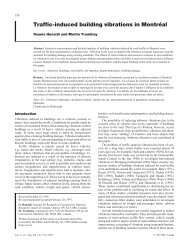
2- The 150 urn (6 mil) polyethylene is placed on the cold side <strong>of</strong> the<br />
<strong>in</strong>ner frame <strong>and</strong> laps over the top <strong>and</strong> bottom plates <strong>and</strong> end studs [Figures 1,<br />
2 <strong>and</strong> 33.<br />
3. The sheath<strong>in</strong>g is applied to hold it <strong>in</strong> place, care be<strong>in</strong>g taken to<br />
protect the air-vapour barrier when the sheath<strong>in</strong>g is cut to size <strong>and</strong> to<br />
ensure i ts <strong>in</strong>tegrity at w<strong>in</strong>dow <strong>and</strong> door open<strong>in</strong>gs.<br />
4. The exterior frame is then canstructed on top <strong>of</strong> the sheathed<br />
<strong>in</strong>terior wall. W<strong>in</strong>dow <strong>and</strong> door open<strong>in</strong>gs are constructed to match exactly<br />
the open<strong>in</strong>gs <strong>in</strong> the <strong>in</strong>terior frame. The <strong>in</strong>ner frame provides the stmctural<br />
strength, therefore the outer one does not require structural headers or<br />
cripple studs f o ~ the w<strong>in</strong>dows <strong>and</strong> doors, or double plates, <strong>and</strong> can be made
<strong>of</strong> 38 x 38 mm (2 x 2) or 38 x 63 mm (2 x 3) material.<br />
5. When the exterior frame has been completed it is squared. It is<br />
then raised onto temporary supports so that the space between <strong>in</strong>ner <strong>and</strong> outer<br />
frames can be Set. Plates <strong>of</strong> plywood, 7 mm (5/M <strong>in</strong>.] are used to hold the<br />
walls at the correct spac<strong>in</strong>g. They are nailed or stapled to the top <strong>and</strong> bottom<br />
plates to complete the fram<strong>in</strong>g <strong>of</strong> the wall, This holds the frames <strong>in</strong> their<br />
proper, relative positions, <strong>and</strong> provides f<strong>in</strong>al straighten<strong>in</strong>g.<br />
6. When the wall is raised to the vertical position, properly located<br />
an the floor arid nailed <strong>in</strong> place, it is necessafy only to brace the wall at<br />
the ends. No further straighten<strong>in</strong>g is necessary before putt<strong>in</strong>g on ro<strong>of</strong><br />
trusses or flam joists for the next stage oE construction. The cont<strong>in</strong>uity<br />
<strong>of</strong> the air-vapour barrier is provided by a bead <strong>of</strong> acoustfcal sealant, which<br />
is added when the polyethylene is applied to the ceil<strong>in</strong>g or over the joist<br />
headers for <strong>in</strong>termediate floors.<br />
The air-vapour barrier is located well sway from the <strong>in</strong>ner face <strong>of</strong> the<br />
wall <strong>and</strong> will be somewhat colder than <strong>in</strong> more common designs. It has been<br />
assumed that at least 2/3 <strong>of</strong> the thermal resistance should be placed on the<br />
cold side <strong>of</strong> the air-vapaur barrier. If the <strong>in</strong>terior stud space conta<strong>in</strong>s<br />
<strong>in</strong>sulation <strong>of</strong> RSI 2.3 [R 13) the total resistance <strong>of</strong> the wall would have to<br />
approach RSI 7 (R 40) to achieve this.<br />
In conventional house design, the Space between the top plate <strong>and</strong> the<br />
ro<strong>of</strong> is not large enough to allow much <strong>in</strong>sulation to be placed on top <strong>of</strong> the<br />
plate. In low energy houses, high lift trusses are used. Insulation 250 to<br />
300 mm (10 to 12 <strong>in</strong>,] thick can be placed directly over the plate <strong>and</strong> still<br />
permit air te flow from the s<strong>of</strong>fit <strong>in</strong>to the attic for attic ventilation.<br />
Plywood sheath<strong>in</strong>g <strong>and</strong>/or cardboard s<strong>of</strong>fit baffles, made for this purpose,<br />
prevent this <strong>in</strong>sulation from fall<strong>in</strong>g <strong>in</strong>to the s<strong>of</strong>fit space. The "high liftn<br />
effect is obta<strong>in</strong>ed by us<strong>in</strong>g trusses 1200 mm (4 ft.) longer than normal or by<br />
us<strong>in</strong>g specially designed ro<strong>of</strong> trusses.<br />
Basements are used <strong>in</strong> some cases; <strong>in</strong> others a crawl space is employed.<br />
In both <strong>in</strong>stances large amounts <strong>of</strong> <strong>in</strong>sulation have been <strong>in</strong>stalled. Special<br />
designs may be needed for basement walls to accommodate the large mount <strong>of</strong><br />
<strong>in</strong>sulation <strong>and</strong> at the same time to meet the structural requirements imposed<br />
by horizontal soil pressures.<br />
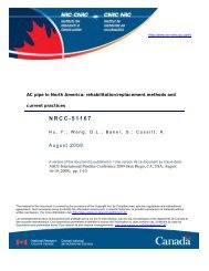
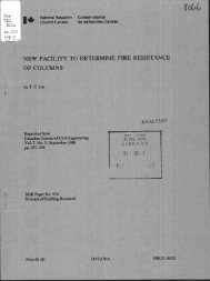
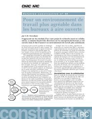
Three different double stud wall designs are shown <strong>in</strong> Figures 1 to 3.<br />
One or more houses have been built follow<strong>in</strong>g each <strong>of</strong> these designs.<br />
<strong>Energy</strong> emsumption data have been obta<strong>in</strong>ed for the house represented<br />
<strong>in</strong> Figure 2, It has two storeys, no basement, <strong>and</strong> a total floor area <strong>of</strong><br />
approximately 250 m2. The estimated annual energy cmsumption for space<br />
heat<strong>in</strong>g based on the.measured energy <strong>in</strong>put to the house was 35 G3.
The estimated space heat<strong>in</strong>g energy consumption far a conventional house <strong>of</strong><br />
that size would be 210 GJ. Both values are based on 5500 'C heat<strong>in</strong>g degreedays<br />
- the number measured <strong>in</strong> the test year. A prelim<strong>in</strong>ary report on energy<br />
consumptions <strong>in</strong> other houses sf similar type has been prepared.1<br />
Pressure tests have been carried out on a number <strong>of</strong> houses, <strong>in</strong>clud<strong>in</strong>g<br />
21 low energy houses, N<strong>in</strong>e were <strong>of</strong> double stud construction with the vapour<br />
barrier placed <strong>in</strong> the wall as shown <strong>in</strong> Figures 1 lo 3. In the twelve other<br />
houses, which had been constructed with careful attention ta the vapour<br />
barrier, it was placed <strong>in</strong> the normal location -- beh<strong>in</strong>d the dry wall. The<br />
air leakage rates at a pressure <strong>of</strong> 50 Pa were compared. For the double stud<br />
walls the average leakage rate was 0-78 air change per hour [ach) with a<br />
st<strong>and</strong>ard deviation <strong>of</strong> 0.32 ach; for the other houses the average leakage<br />
rate was 1.80 ach <strong>and</strong> the st<strong>and</strong>ard deviation was 0.88 ach. For these cases<br />
it appears that the double stud design resulted <strong>in</strong> significantly lower air<br />
leakage rates <strong>and</strong> suggests that air tightness is more easily achieved with<br />
this design than with other types <strong>of</strong> construction.<br />
<strong>Construction</strong> costs for a double stud wall will be significantly higher<br />
than those <strong>of</strong> conventional houses. Tests <strong>in</strong>dicate that with proper<br />
construction practices the expected sav<strong>in</strong>gs <strong>in</strong> energy for space heat<strong>in</strong>g are<br />
acllieved. The economics cannot be properly assessed at this time s<strong>in</strong>ce a<br />
simple comparison <strong>of</strong> canstmction costs <strong>and</strong> energy saved does nut <strong>in</strong>clude<br />
rhe benefits to the country <strong>of</strong> sav<strong>in</strong>gs <strong>in</strong> non-renewable resources or reduced<br />
cost to municipal <strong>and</strong> prov<strong>in</strong>cial governments <strong>of</strong> services required to supply<br />
energy to the houses.<br />
Reference<br />
Dumont, R. S. , Orr, H. W., Hedl<strong>in</strong>, C. P . <strong>and</strong> Makohon. J. T. Measured<br />
<strong>Energy</strong> Consumption <strong>of</strong> a Group <strong>of</strong> <strong>Low</strong> <strong>Energy</strong> <strong>Houses</strong>. Pracs.,<br />
Jo<strong>in</strong>t Solar Cunferenee, University sf British Columbia,<br />
Vancouver, B.C., 4 to 10 August 1980. The Solar <strong>Energy</strong><br />
Socfety <strong>of</strong> Canada Inc. <strong>and</strong> the Pacific Northwest Solar<br />
<strong>Energy</strong> Association. p.294-293.
treated cardboard<br />
sheath<strong>in</strong>g-<br />
-<br />
* 38XMmm[2X3<strong>in</strong>)<br />
stud 40Q mm (16 <strong>in</strong>) O.C.<br />
150 urn (6 mil) vapour barrier<br />
38X89m(2X4<strong>in</strong>)stud600m (24<strong>in</strong>) 0.C.<br />
7.5 rnm (V16 <strong>in</strong>) plywoad<br />
38 X &I mrn (2x3 h)<br />
blocki ng<br />
12.7 rnm (1/2 <strong>in</strong>) plywood<br />
build<strong>in</strong>g paper<br />
<strong>and</strong> sid<strong>in</strong>g<br />
38 X 89 mrn (2 X 4 <strong>in</strong>) stud 400 mm (16 <strong>in</strong>) O.C.<br />
J(E38~64rnm (2X3<strong>in</strong>)<br />
stud 400 mrn (16 <strong>in</strong>) O.C.<br />
12.7 rnm (112 <strong>in</strong>) plywood<br />
600 mm mad space (24 <strong>in</strong> ) m<strong>in</strong><br />
I50 urn (6 mil) moisture barrier<br />
NOTE: All wmd with<strong>in</strong> 225 mm <strong>of</strong> tM earth<br />
should be pressure treated<br />
FIGURE I Wall section - grade beam <strong>and</strong> pil<strong>in</strong>g foundation
treated cardboard<br />
33X64mm{2X3<strong>in</strong>)skrd<br />
400 rnm (16 <strong>in</strong>) O.C.<br />
150 p (6 mil) vapour barrier<br />
38 X 89 mm (2 X 4 <strong>in</strong>) m d 400 mm (16 <strong>in</strong>) O.C.<br />
127 mrn (1~2 <strong>in</strong>) plywood sheath<strong>in</strong>g<br />
buiid<strong>in</strong>g paper <strong>and</strong> sid<strong>in</strong>g<br />
75 mm (5116 <strong>in</strong>) plywod<br />
38 X 64 rnm (2 X 3 <strong>in</strong>) block<strong>in</strong>g<br />
12.7 mm (1/2 <strong>in</strong>) plywd<br />
12.7 mrn (1 /2 <strong>in</strong>) PWF sheath<strong>in</strong>g<br />
38XWmrn (2 X4<strong>in</strong>)<br />
PWF 400 mrn (16 <strong>in</strong>) O.C.<br />
mrn (1/2 <strong>in</strong>) PWF ply\rrood<br />
dra<strong>in</strong> holes<br />
127 rrm~ (V2 <strong>in</strong>) plywd hathiq<br />
38 X 140 rnm (2 X 6 <strong>in</strong>) stud 400 mm ( f 6 <strong>in</strong>) OC.<br />
RSI 35<br />
RSI 49 (m)<br />
RSI 2.1 (Rf2)<br />
38 X 89 rnm (2 X 4 <strong>in</strong>) PWF block<strong>in</strong>g<br />
+$00 mm (15 <strong>in</strong>) <strong>and</strong> +I000 rnm (45 <strong>in</strong>) each<br />
, AS1 4.9 (R28)<br />
stud<br />
38 X 89 mm (2 X 4 <strong>in</strong>)<br />
PWF 400 mrn (1 6 <strong>in</strong>) O.C.<br />
pn (6 mil) moisture taanier<br />
X 140rnm (2X6<strong>in</strong>) PWF<br />
~3 f<strong>in</strong>es granular foot<strong>in</strong>g<br />
FIGURE 2 Wal- - k&d Hwod f wnm
acoustical sealant<br />
150 pm (6 mil) vapour barrier<br />
38X@rnrn(ZX3<strong>in</strong>)stud<br />
400 mm (16 <strong>in</strong>) O.C.<br />
38 X 89 mrn (2 X 4 <strong>in</strong>) stud 400 mm (16 <strong>in</strong>) O.C.<br />
build<strong>in</strong>g paper <strong>and</strong> sid<strong>in</strong>g<br />
RSI 4.9 (RBI m<strong>in</strong>imum<br />
7.5 mrn (5/16 <strong>in</strong>) plywood<br />
NOTE<br />
soil must be WF grade.<br />
38 X 89 mm (2 X 4 <strong>in</strong>) 600 mm (24 <strong>in</strong>) O.C.<br />
38 X89 mn (2 X4 <strong>in</strong>) 800 mm (32 <strong>in</strong>) O.C.<br />
or dher appropriate support for outer dl<br />
grad dra<strong>in</strong>age layer<br />
FiGURE 3 Wall sedion - concrete wall <strong>and</strong> foot<strong>in</strong>g foundation