WRA 200-S8/S17 AUTOMATIC SPRAY GUN - Anest Iwata
WRA 200-S8/S17 AUTOMATIC SPRAY GUN - Anest Iwata
WRA 200-S8/S17 AUTOMATIC SPRAY GUN - Anest Iwata

Create successful ePaper yourself
Turn your PDF publications into a flip-book with our unique Google optimized e-Paper software.
MJ1674-02EREV.0<br />
Instruction Manual<br />
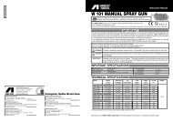
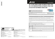
<strong>WRA</strong> <strong>200</strong>-<strong>S8</strong>/<strong>S17</strong> <strong>AUTOMATIC</strong> <strong>SPRAY</strong> <strong>GUN</strong><br />
GB<br />
Before use, adjustment or maintenance, it is important to read this instruction manual very care<br />
fully. This manual must be stored in a safe place for any future reference that may be necessary.<br />
This ANEST IWATA spray guns kit complies to ATEX regulations 94/9/EC,<br />
Protection level: II 2 G X Suitable for using Zones 1 and 2.<br />
X marking: Any static electricity discharge from the spray gun is to be diverted to the ground via the conductive air hose as stipulated.<br />
IMPORTANT<br />
This automatic spray gun should be operated only by an adequately trained operator for safe use and maintenance of the equipment.<br />
Any misuse or handling other than those indicated in this Instruction Manual is not covered by guarantee.<br />
ANEST IWATA disclaims all responsibility for any accident or damage caused by failure observing the operational and safety procedures<br />
as from this manual. In the interest of user friendliness, this manual contains information in a brief and concise form.<br />
For any additional information you may require regarding the automatic spray gun operations, or if any missing parts or any damage<br />
during transportation is found, or details of training courses, please contact your nearest ANEST IWATA Company (see last<br />
cover page).<br />
Be sure to observe warnings and cautions in this instruction manual.<br />
If not, it can cause paint ejection and serious bodily injury by drawing organic solvent.<br />
Be sure to observe following marked items which are especially important.<br />
WARNING<br />
CAUTION<br />
IMPORTANT<br />
Indicates a potentially hazardous situation which, if not avoided, may result in serious injury or loss of life.<br />
Indicates a potentially hazardous situation which, if not avoided, may result in minor or moderate injury or property<br />
damage.<br />
Indicates notes which we ask you to observe. The safety precautions in this instruction manual are the minimum<br />
necessary conditions. Follow national and local regulations regarding fire prevention, electricity and<br />
safety as well as your own company regulations.<br />
ANEST IWATA Europe S.r.l.<br />
46, Corso Vigevano 10155, Torino Italy<br />
Direct Tel. +39 011 - 22 74 402<br />
Fax +39 011 - 22 74 406<br />
info@anest-iwataeu.com<br />
www.anest-iwataeu.com<br />
ANEST IWATA Italia S.r.l.<br />
46, Corso Vigevano 10155, Torino (Italy)<br />
Tel. diretto +39 011 - 24 80 868 - Fax: +39 011 - 85 19 44<br />
info@anest-iwata.it<br />
www.anest-iwata.it<br />
ANEST IWATA Iberica<br />
Calle de Les Teixidores, 3-5<br />
08918 - Badalona (Barcelona)<br />
Tel.:+34 933 20 59 93 - Fax.:+34 933 20 59 65<br />
info@anest-iwata.es<br />
www.anest-iwata.es<br />
ANEST IWATA Europe S.r.l.<br />
NIEDERLASSUNG DEUTSCHLAND<br />
Dorfäckerstr. 23/1, 74248 Ellhofen<br />
Telefon: +49 (0) 7134- 917368 - Fax: +49 (0) 7134 - 917378<br />
Handy: +49 (0) 172 - 62 74 542<br />
info@anest-iwata.de<br />
www.anest-iwata.de<br />
European Sales Branches:<br />
ANEST IWATA Scandinavia<br />
Ögärdesvägen 6C, 433 30 PARTILLE - Sweden<br />
Tel. +46 (0)31 - 340 28 60 - Fax +46 (0)31 - 340 28 69<br />
info@anest-iwata.se<br />
www.anest-iwata.se<br />
ANEST IWATA France<br />
25 rue de Madrid - 38070 St Quentin Fallavier - France<br />
Tél. +33 (0)4 - 74 94 59 69 - Fax +33 (0)4 - 74 94 34 39<br />
info@anest-iwata.fr<br />
www.anest-iwata.fr<br />
ANEST IWATA U.K.<br />
Unit 10 Little End Road - Eaton Socon<br />
St. Neots - CAMBRIDGESHIRE<br />
PE19 8JH<br />
Tel.: +44 (0) 1480 405419 Fax: +44 (0) 1480 217610<br />
enquiries@anest-iwata.co.uk<br />
www.anest-iwata.co.uk<br />
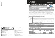
IMPORTANT SPECIFICATIONS<br />
Max. Pressure: 6.8 bar (98 PSI) Max. Temperature:<br />
Noise Level (LAeqT): 76.8 dB (A) <strong>WRA</strong> <strong>200</strong> <strong>S8</strong> * Atmosphere 5 ~ 40 °C<br />
Noise Level (LAeqT): 82.4 dB (A) <strong>WRA</strong> <strong>200</strong> <strong>S17</strong> * Air and fluid 5 ~ 43 °C<br />
Air connection: Rc 1/8”<br />
Fluid connection: Rc 1/8”<br />
* Measuring point: 1m backwards from gun, 1,6 m height<br />
TECHNICAL SPECIFICATIONS<br />
Model Nozzle Air Cap *Air pressure Fluid Air Pattern Weight<br />
orifice Set bar (PSI) output comsumption width<br />
mm(in) Mark Atomizing air Fan air ml/m (cfm) mm g (lbs)<br />
<strong>WRA</strong>-<strong>200</strong> Pressure feed<br />
<strong>WRA</strong>-<strong>200</strong>-<strong>S8</strong> 1.2 (0.047) LV2 2.4 (34) 2.7 (38) 500 530 (18.7) 400 (15.7) 460 (1.03)<br />
<strong>WRA</strong>-<strong>200</strong>-<strong>S17</strong>-08P 0.8 (0.031) 1.5 (21) 2.0(28) 150 420 (14.8) <strong>200</strong> (7.9) 460 (1.03)<br />
460 (1.03)<br />
<strong>WRA</strong>-<strong>200</strong>-<strong>S17</strong>-10P 1.0 (0.039) WB1 1.5 (21) 2.0 (28) <strong>200</strong> 420 (14.8) 240 (9.4) 460 (1.03)<br />
<strong>WRA</strong>-<strong>200</strong>-<strong>S17</strong>-12P 1.2 (0.047) 1.5 (21) 2.0(28) 250 420 (14.8) 260 (10.2) 460 (1.03)<br />
NOTE: *Air pressure means pressure at gun inlet when air valve is opened and air flows.<br />
Manufactured by:<br />
ANEST IWATA Corporation 3176,Shinyoshida-cho, Kohoku-ku, Yokohama, 223-8501 Japan
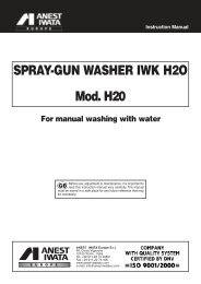
SAFETY WARNINGS<br />
COMMENTS<br />
FIRE OR EXPLOSION HAZARD<br />
1. Spark and open flames are strictly prohibited.<br />
Paints can be highly flammable and can cause fire.<br />
Avoid any ignition sources such as smoking, open flames, electrical goods, etc.<br />
2. Never use the following HALGOGENATED HYDROCARBON SOLVENTS<br />
which can cause cracks or dissolution on gun body (aluminum) by chemical reaction.<br />
- Unsuitable solvents: methyl chloride, dichloromethane, 1.2-dichloroethane, carbon tetrachloride,<br />
trichloroethylene, 1.1.1- trichloroethane.<br />
- Be sure that all fluids and solvents are compatible with gun parts.<br />
We are ready to supply a material list used in the product.<br />
3. Securely ground spray gun. Use air hose with built-in ground wire or use grounded gun stay.<br />
Ground resistance : Less than 1MΩ. Check the earth stability periodically.<br />
If not, insufficient grounding can cause fire and explosion due to static electric sparking.<br />
IMPROPER USE OF EQUIPMENT<br />
1. Never point gun towards people or animals.<br />
If done, it can cause inflammation of eyes and skin or bodily injury.<br />
2. Never exceed maximum operating pressure and maximum operating temperature.<br />
3. Be sure to release air and fluid pressures before cleaning, disassembling or servicing.<br />
If not, remaining pressure can cause bodily injury due to improper operation or scattering of cleaning<br />
liquid. In order to release pressure, first stop supply of compressed air, fluid and thinner to automatic spray<br />
gun. Next, supply only piston operating air and exhaust fluid by operating fluid needle, which results in automatic supply stop<br />
of all compressed air.<br />
4. Tip of fluid needle set has a sharp point.<br />
Do not touch the tip of fluid needle during maintenance for the protection of the human body.<br />
PROTECTION OF HUMAN BODY<br />
1. Use in a well-ventilated site by using spray booth.<br />
If not, poor ventilation can cause organic solvent poisoning and catch<br />
fire.<br />
2. Always wear protective gear: safety glasses, mask, gloves.<br />
If not, cleaning liquid, etc., can cause inflammation of eyes and skin.<br />
If you feel something wrong with eyes or skin, immediately see a doctor.<br />
3. Wear earplugs if necessary.<br />
Noise level can exceed 85 dB(A), depending on operating conditions and painting site.<br />
OTHER PRECAUTIONS<br />
1. Never alter this spray gun.<br />
If done, it can cause insufficient performance and failure.<br />
2. Enter working areas of other equipment (robots, reciprocators, etc.) after machines are turned off.<br />
If not, contact with them can cause injury.<br />
3. Never spray foods or chemicals through this gun.<br />
If done, it can cause accident by corrosion of fluid passages or adversely affect health by mixed foreign matter.<br />
4. If something goes wrong, immediately stop operation and find the cause. Do not use again until you have solved the<br />
problem.<br />
2<br />
7
TROUBLESHOOTING<br />
Spray Pattern Problems Remedies<br />
PROBLEMS AND REMEDIES<br />
Problem Where it Parts to be Cause Remedy<br />
occurred checked Retighten Adjust Clean Replace<br />
Paint leaks<br />
1. Air enters between fluid nozzle and 1. Remove fluid nozzle to clean seat.<br />
Fluttering tapered seat of gun body. If it is damaged, replace nozzle.<br />
Fluid nozzle<br />
2. Air enters at fluid hose joint 2. Fully tighten joint section.<br />
1. Paint buildup on air cap partially 1. Remove obstructions from horn holes.<br />
Crescent clogs horn holes. Air pressure from But do not use metal<br />
both horns differs.<br />
objects to clean horn holes.<br />
1. Paint buildup or damage on fluid nozzle cir- 1. Remove obstructions.<br />
Inclined cumference and air cap center. Replace if damaged.<br />
2. Fluid nozzle is not properly fitted. 2. Remove fluid nozzle, clean seated section.<br />
1. Paint viscosity too low. 1. Add paint to increase viscosity.<br />
Split 2. Fluid output too high. 2. Tighten fluid adj. knob to reduce fluid output<br />
or reduce air pressure for Fan.<br />
1. Paint viscosity is too high. 1. Add thinner to reduce viscosity.<br />
Heavy 2. Fluid output is too low. 2. Turn fluid adj. knob counter-clockwise to<br />
Center<br />
increase fluid output or increase air pressure<br />
for Fan.<br />
1. Fluid nozzle and fluid needle set are 1. Clean or replace fluid nozzle and fluid<br />
Spit not seated properly. needle set.<br />
2. Paint buildup inside air cap set. 2. Clean air cap set.<br />
Fluid nozzle<br />
fluid needle * Dirt or damage, x x<br />
wear on seat surface<br />
* Wear on needle spring x<br />
* Needle does not return due<br />
to paint buildup on x x<br />
Fluid needle Fluid needle packing- fluid needle.<br />
packing packing seat<br />
* Wear x<br />
* Insufficient tightening x<br />
Gun body set- Bolt with hex. hole * Insufficient tightening x<br />
Manifold unit<br />
Fluid adj. knob. * Insufficient opening x<br />
Paint does<br />
not flow Tip of gun Tip hole of nozzle * Clogged x<br />
Paint filter * Clogged x x<br />
HOW TO CONNECT<br />
IMPORTANT<br />
THIS <strong>GUN</strong> SHOULD BE OPERATED BY ADEQUATELY TRAINED OPERATORS ONLY.<br />
ENSURE THAT THE <strong>GUN</strong> HAS NOT BEEN DAMAGED DURING TRANSPORTATION.<br />
CAUTION<br />
- Use clean air filtered through air dryer and air filter. If not, dirty air can cause painting failure.<br />
- When you use this gun for the first time after purchasing, clean fluid passages spraying thinner<br />
to remove rust preventive oil.<br />
If not, remaining preventive oil can cause painting failure such as fish eyes.<br />
- Use two-way or three-way solenoid valve of more than ø 4 inner dia. cross-sectional area and air hose of over<br />
ø 6 inner dia. and less than 10m length. If not, small dia. of solenoid valve and longer air hose between three-way<br />
solenoid valve and gun can cause delay in operation.<br />
- Firmly fix hose to spray gun. If not, disconnection of hose and drop of container can cause bodily injury.<br />
1. Fit the gun to fitting stay, aim at spraying direction and fix it with fixing bolts.<br />
2. Connect atomizing air hose to atomizing air inlet (CAP marked side) fan air hose to fan air inlet (FAN marked side) and operating<br />
air hose to operating air inlet (CYL marked side) tightly.<br />
3. Connect fluid hose to fluid inlet (FLU marked side) tightly.<br />
4. Flush the gun fluid passages with a compatible solvent.<br />
5. Supply paint, test spray and adjust fluid output, air volume and pattern width.<br />
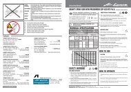
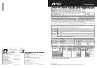
CONNECTING EXAMPLE<br />
Hole for fitting stay<br />
Air Filter<br />
Paint pump<br />
Air Compressor<br />
Air Dryer<br />
Paint flow<br />
meter<br />
Air Regulator 2-way solenoid valve<br />
Fan air (TO FAN)<br />
Air Regulator 2-way solenoid valve<br />
Atomizing air (TO CAP)<br />
Air Regulator 3-way solenoid valve<br />
Back pressure valve<br />
Screw for fitting. Use bolt set ( Standard accessory) for fitting stay.<br />
Operating air (TO CYL)<br />
Fluid line (TO FLU)<br />
In case of circulation usage, connect<br />
to CIR marked side.<br />
Pull<br />
Gun body<br />
Plug<br />
Screw (Standard Accessory)<br />
6<br />
HOW TO CHANGE UNIONS FOR CIRCULATION USAGE<br />
IMPORTANT<br />
1. If the hex. nut is connected to outlet (CIR marked side on manifold) remouve it from gun body with 5 mm<br />
allen wrench.<br />
2. Divide gun unit to gun body set and manifold unit.<br />
3. Pull plug out from gun body, with attached screw as standard accessory.<br />
4. Set o’ring as standard accessory to fluid passage where removed plug.<br />
5. Tighten gun body set and manifold unit with hex. bolt tightly with manifold packing between them.<br />
6. Connect fitting joint tightly to circulation side (CIR).<br />
7. Connect fluid hose to the joint.<br />
3
HOW TO OPERATE<br />
Suggested operating air pressure is 3 to 4 bar (43 to 57 PSI).<br />
NOTE: Valve orifice inside two-way or three- way solenoid valve should be minimum 4mm (0.157 in) and also operating air hose<br />
length should be within 10m (32.8ft) with the inner diameter more than 6mm (0.236in) to avoid delayed operation and any kind of<br />
failure.<br />
Each air pressure for atomizing or fan, varies according to spray conditions, adjust as specified on above specifications table.<br />
Recommended paint viscosity differs according to paint property and painting conditions. 15 to 23 sec/Ford cup# 4 is recommendable.<br />
Set the spray distance from the gun to the work piece as near as possible within the range of 150-250 mm ( 5.9-9.8 in).<br />
SPARE PARTS LIST<br />
MAINTENANCE AND INSPECTION<br />
WARNING<br />
- First release air and fluid pressure fully according to item No. 3 of “Improper use of equipment” of WARNING on<br />
page 2.<br />
- Tip of fluid needle set has a sharp point. Do not touch the tip of needle valve during maintenance for protection of<br />
the human body.<br />
- Be careful not to damage the tip of the fluid nozzle or not put your hand on it.<br />
- Only an experienced person who is fully conversant with the equipment can do maintenance and inspection.<br />
CAUTION<br />
- Never use commercial or other parts instead of ANEST IWATA original spare parts.<br />
- Never immerse the whole gun into liquid such as thinner.<br />
- Never soak air cap set in solvent for extended period even if cleaning. It can cause defective pattern.<br />
- Never damage holes of air cap, fluid nozzle or fluid needle.<br />
Step-by-step procedure<br />
Important<br />
1. Clean fluid passages and air cap set. 1. Incomplete cleaning can fail pattern shape and uniform particles.<br />
Spray a small amount of thinner to clean fluid passages.<br />
Especially clean fully and promptly after use with two-component paint.<br />
2. Clean each section with brush soaked with thinner and wipe out with waste cloth. 2. Do not immerse the whole gun in thinner. If done, it can damage parts.<br />
When cleaning, never scratch any holes of air cap set, of fluid nozzle,<br />
or fluid needle set.<br />
DESCRIPTION<br />
REF.<br />
Air cap set 1<br />
Fluid nozzle-needle set 2<br />
Gun body set 3<br />
Gun body 3-1<br />
O’ring 3-2<br />
Model Fluid nozzle Fluid needle<br />
Orifice Ø mm (in) Mark Mark<br />
<strong>WRA</strong>-<strong>200</strong> <strong>S8</strong> 1.2 (0.047) WA<strong>200</strong>/12 <strong>WRA</strong>12<br />
<strong>WRA</strong>-<strong>200</strong> <strong>S17</strong>-08P 0.8 (0.031) WA<strong>200</strong>/08 <strong>WRA</strong>08<br />
<strong>WRA</strong>-<strong>200</strong> <strong>S17</strong>-10P 1.0 (0.039) WA<strong>200</strong>/10 <strong>WRA</strong>10<br />
<strong>WRA</strong>-<strong>200</strong> <strong>S17</strong>-12P 1.2 (0.047) WA<strong>200</strong>/12 <strong>WRA</strong>12<br />
3. Before disassembly, fully clean fluid passages. 3. During disassembly, do not scratch seat section.<br />
Plug 3-3<br />
(1) Disassemble fluid nozzle. (1) Remove fluid nozzle after removing fluid needle set or while keeping<br />
Fluid needle packing set 4<br />
Use ring spanner, box wrench or optional exclusive spanner to disassemble<br />
fluid needle pulled, in order to protect seat section.<br />
Piston 5<br />
fluid nozzle.<br />
Needle screw 6<br />
Piston packing 7<br />
(2)Disassemble fluid needle set.<br />
Remove fluid adj. set and pull out fluid needle set from gun body.<br />
Pay attention so that spring does not suddenly fly out since fluid adj. set is strongly<br />
pushed by fluid needle spring and piston spring.<br />
(2) Pull fluid needle set after loosening fluid needle packing set to protect fluid<br />
needle packing set.<br />
Piston spring 8<br />
Fluid adj. set 9<br />
Stop ring 9-1<br />
Ball 9-2<br />
Marked parts are wearable parts.<br />
- When ordering parts, specify gun’s model, part name<br />
with ref. No, and marked No. of air cap set, fluid nozzle<br />
and fluid needle set.<br />
Where to inspect<br />
Parts replacement standard<br />
1. Each hole passage of air cap and fluid nozzle Replace if it is crushed or deformed.<br />
2. Packing and O ring Replace if it is deformed or worn out.<br />
3. Leakage from seat section between fluid nozzle and fluid needle set Replace them if leakage does not stop after fully cleaning fluid nozzle and<br />
fluid needle set. If you replace fluid nozzle or fluid needle set only,<br />
fully match them and confirm that there is no leakage.<br />
Fluid adj. spring 9-3<br />
Manifold unit 10<br />
Manifold packing 11<br />
O’ring 12<br />
Bolt with hex. hole 13<br />
Fixing bolt set 14<br />
Bolt with hexagon hole 15<br />
- When replacing fluid nozzle or/and fluid needle, please<br />
order nozzle needle set.<br />
4<br />
Screw 16<br />
5