
Download 2100-A16 Installation Guide - Intech Instruments Ltd
Download 2100-A16 Installation Guide - Intech Instruments Ltd
Download 2100-A16 Installation Guide - Intech Instruments Ltd

You also want an ePaper? Increase the reach of your titles
YUMPU automatically turns print PDFs into web optimized ePapers that Google loves.
INTECH Micro<br />
<strong>2100</strong>-<strong>A16</strong> REV 1.3<br />
REG ISTERED<br />
ISO9001<br />
MANU<br />
CTURER<br />
F<br />
A<br />
TECHNOLOGY<br />
& QUALITY<br />
AWAR D<br />
Z985<br />
<strong>Installation</strong> <strong>Guide</strong>.<br />
14.01-1
Section A. Description, Ordering and Specifications.<br />
<strong>2100</strong>-<strong>A16</strong> <strong>Installation</strong> <strong>Guide</strong> Index.<br />
Section A. Description, Ordering and Specifications.<br />
Index. Page 2<br />
Features and Ordering Information. Page 3<br />
Specifications. Page 4<br />
Terminals and layout. Page 6<br />
Dimensions. Page 7<br />
Section B: Jumpers and LED Functions Tables.<br />
S1 Function Settings. Page 7<br />
H1 Power Supply Settings. Page 7<br />
H2 Comms Settings. Page 7<br />
H4 RTD Settings. Page 7<br />
LED Descriptions. Page 7<br />
Section C. Input and Output Connection Diagrams.<br />
Milliamp Inputs. Page 8<br />
Millivolts and Voltage Inputs. Page 8<br />
RTD Inputs. Page 9<br />
Thermocouple (T/C) Inputs. Page 9<br />
Thermocouple Upscale (US) / Downscale (DS) Drive. Page 9<br />
Connection Example Diagram for Digital Inputs. Page 10<br />
Connection Diagram Using an LPI-D Current Loop Isolator on the Input. Page 10<br />
Connection Diagram Using an XI-P1 Current Loop Isolator on the Input. Page 10<br />
Connection Example Diagram for Digital Outputs. Page 10<br />
Section D. Connecting to a Microscan Scada System.<br />
Analogue Input Expansion - Using <strong>2100</strong>-M Analogue Input Multiplexer. Page 11<br />
Option 1. 5 Wire Connection Diagram. Page 11<br />
Option 2. 4 Wire Connection Diagram. Page 11<br />
Analogue Outputs Controlled by the Scada. Page 12<br />
<strong>2100</strong>-RL2 2 Relay Slave Board Connection. Page 12<br />
<strong>2100</strong>-ME Memory Expansion. Page 12<br />
<strong>2100</strong>-R2 Relay Expansion. Page 13<br />
RS485 Serial Connection. Page 14<br />
RS422 Serial Connection. Page 14<br />
RS232 Serial Connection. Page 15<br />
RS232 Radio Modem Serial Connection. Page 15<br />
Station Number Programming and Serial Numbers. Page 15<br />
Station Software Programming. Page 15<br />
TXE and TX Delay Settings and Table. Page 16<br />
Section E. Connecting to a PLC.<br />
Mode 3. Clock & Reset Channel Selection. Page 16<br />
Mode 4. Binary Channel Selection. Page 17<br />
Connection examples of a PLC with open collectors<br />
commoned to 24V of an external power supply. Page 18<br />
commoned to the 20V of the first <strong>2100</strong>-<strong>A16</strong> power supply. Page 18<br />
commoned to 0V of an external power supply. Page 19<br />
commoned to COM of the first <strong>2100</strong>-<strong>A16</strong> Page 19<br />
PLC RTX Fail Safe System Page 20<br />
Analogue Signal Converted to Frequency for a PLC, using a TWI-FO. Page 20<br />
Section F. Communications.<br />
Modbus RTU Communication Protocol. Page 20<br />
Modbus RTU Station Addresses. Page 21<br />
Using the Modbus Protocol. Page 21<br />
<strong>2100</strong>-<strong>A16</strong> Modbus Notes. Page 23<br />
<strong>2100</strong>-<strong>A16</strong>-NET Ethernet 10/100. Page 23<br />
Section G. Wiring, <strong>Installation</strong>, and Maintenance.<br />
Mounting Page 25<br />
Cover Removal and Fitting. Page 25<br />
Power Supply Wiring. Page 25<br />
RS422/485 Comms Signal Cabling. Page 26<br />
Cautions Using Differential Inputs. Page 26<br />
Cautions Using Analogue Inputs. Page 26<br />
Analogue Signal Wiring. Page 26<br />
RTDs Page 27<br />
Thermocouples Page 27<br />
Commisioning. Page 27<br />
Maintenance. Page 28<br />
14.02-2
INTECH Micro<br />
<strong>2100</strong>-<strong>A16</strong> Rev 1.3<br />
Features.<br />
• 16 Universal Analogue Inputs.<br />
• Each Input Individually Selected & Scaled.<br />
• 16 Bit Resolution.<br />
• Differential Input for T/C, mV, V, & mA.<br />
• T/C: B, E, K, J, N, R, S, T.<br />
• RTD: 0~25C to -200~850C.<br />
• mV: 0~25mV to ±500mV.<br />
• V: 0~1V to ±15V.<br />
• mA: 0~1mA to ±100mA.<br />
• 2 Analogue Ouputs.<br />
• Four Digital, Isolated, Optocoupler Inputs.<br />
• Two Digital, Isolated, Relay Outputs.<br />
• RS422/RS485 Up to 1200m.<br />
• RS232 Cost Effective Radio <strong>Installation</strong>.<br />
• RS232 Cost Effective PC or PLC AI Expansion.<br />
• Modbus RTU and Modbus TCP Options Available.<br />
• Clock/Reset Drive up to Four <strong>2100</strong>-Ms.<br />
• Selectable Baud Rates.<br />
• Digital Inputs:<br />
- State or Count.<br />
- Speeds to 50Hz.<br />
• Interface for <strong>2100</strong>-R2 (16 Relays) or <strong>2100</strong>-ME (Memory).<br />
• Easy Programming Via Microscan Maps.<br />
• Programmable Station Number.<br />
• Programmable Relay States - NO or NC.<br />
• Comms Failure Time-out Using Relay 2.<br />
• Comms TXE and TX Delay Programming.<br />
• Programming Information Retained on Power Down.<br />
• Universal AC/DC Power Supply.<br />
• Easy to Install.<br />
• Compact DIN Rail Mount Enclosure<br />
16 Universal Analogue Inputs.<br />
4 Digital Inputs. 2 Analogue<br />
Outputs. 2 Relay Output.<br />
ISO9001<br />
TECHNOLOGY<br />
& QUALITY<br />
AWAR D<br />
<strong>2100</strong> models include:<br />
<strong>2100</strong>-4S : RS422 to RS485 Converter.<br />
<strong>2100</strong>-<strong>A16</strong> :16AI, 4DI, 2 Relay Out, 2 AO.<br />
<strong>2100</strong>-A4 :4AI, 4DI, 4 Relay Out, 2 AO.<br />
<strong>2100</strong>-A4e :4AI, 4DI, 8 Relay Out, 2 AO.<br />
<strong>2100</strong>-AO :8 AO, 8 AI, 12 DI, 2 Relay Out.<br />
<strong>2100</strong>-D :12DI, 12 Relay Out.<br />
<strong>2100</strong>-IS :Isolated RS232 to RS422/485.<br />
<strong>2100</strong>-M :16AI Multiplexer.<br />
<strong>2100</strong>-ME :Memory Expansion for <strong>2100</strong>-A.<br />
<strong>2100</strong>-NET :Isolated Ethernet to RS232/422/485.<br />
<strong>2100</strong>-NS :Non-Isolated RS232 to RS422/485.<br />
<strong>2100</strong>-R2 :16 Relay Expansion for <strong>2100</strong>-A.<br />
<strong>2100</strong>-RL2 :2 Relay Expansion for <strong>2100</strong>-A.<br />
Ordering Information.<br />
<strong>2100</strong>-<strong>A16</strong> Rev1 -X Standard Unit: Analogue Inputs Pt100, 0~100C; Analogue Outputs,<br />
4~20mA; RS485 Comms; 85~264Vac/dc Power Supply.<br />
<strong>2100</strong>-<strong>A16</strong> Rev1<br />
O AO C PS<br />
Ranging Options for <strong>2100</strong>-A1<br />
6<br />
Supplied with Option O Analogue<br />
Out<br />
AO<br />
COMMS<br />
C Power<br />
Supply P<br />
<strong>2100</strong>-ME Memory Board ME<br />
4~20mA<br />
A1<br />
RS232<br />
( 1)<br />
232<br />
85~264Vac/dc<br />
H<br />
<strong>2100</strong>-R2<br />
16 Relay Expander R2<br />
0~20mA<br />
A2<br />
RS422<br />
422<br />
23~90Vdc<br />
M<br />
<strong>2100</strong>-RL2<br />
2 Relay Slave Bd RL2<br />
2~10V<br />
V1<br />
RS485<br />
485<br />
10~28Vac/dc<br />
L<br />
No<br />
Options<br />
N 0~10V<br />
V2<br />
Etherne<br />
t NET<br />
( S<br />
Note 1. The RS232 Comms. version comes complete with a RS232 kit, required for connecting the <strong>2100</strong>-<strong>A16</strong> to a PC,<br />
etc. The kit contains: 1 x 5m RS232 cable; (2,10 & 15m available.) 1 x 9 pin D type (25 pin D type available).<br />
Note 2: The <strong>2100</strong>-<strong>A16</strong> is factory set to RS232 or RS422/485. The <strong>2100</strong>-<strong>A16</strong>-X is field selectable for RS422 or RS485,<br />
and H or M power supply.<br />
Note 3: The Microscan, PLC Message and Modbus RTU Comms Protocols come standard on all units.<br />
Note 4: Power supply ‘H’ is field selectable for ’M’, and ‘M’ for ‘H’. Power supply ‘L’ must be ordered separately.<br />
Z985<br />
Ordering Examples.<br />
1/ <strong>2100</strong>-<strong>A16</strong>-ME-A1-232-L <strong>2100</strong>-<strong>A16</strong>; Memory Board Fitted; 4~20mA AO; RS232 Comms; 10~28Vac/dc PS.<br />
2/ <strong>2100</strong>-<strong>A16</strong>-N-V2-485-H <strong>2100</strong>-<strong>A16</strong>; 0~10V AO; RS485 Comms; 85~264Vac/dc Power Supply.<br />
Quality Assurance Programme.<br />
The modern technology and strict procedures of the ISO9001 Quality Assurance Programme applied during design,<br />
development, production and final inspection grant long term reliability of the instrument. This instrument has been<br />
designed and built to comply with EMC and Safety Standards requirements.<br />
14.02-3<br />
REG ISTERED<br />
MANU<br />
CTURER<br />
F<br />
A
<strong>2100</strong>-<strong>A16</strong> Input Specifications.<br />
Note: Each input can be individually software selected & scaled within the span limits listed below.<br />
Input Resolution<br />
Input Differential<br />
16 Bits, 50,000 Steps Average. (Some ranges may differ.)<br />
18Vac/dc peak (sum of ac + dc) between any two channels.<br />
Note: RTD Pt100/Pt1000 are single ended.<br />
mV / V Inputs:<br />
- Input Impedance >1M @ 10V to >100k @ 25mV.<br />
- Maximum Over-range 18Vdc Continuous.<br />
- mV Ranges 0~25mV, 0~50mV, 0~100mV, 0~250mV, 0~500mV.<br />
±25mV, ±50mV, ±100mV, ±250mV, ±500mV.<br />
- V Ranges 0~1V, 0~2.5V, 0~5V, 0~10V, 0~15V.<br />
±1V, ±2.5V, ±5V, ±10V, ±15V.<br />
mA Inputs: note 2<br />
- Input Resistance 25<br />
- Maximum Over-range 100mAdc Continuous.<br />
- mA Ranges 0~1mA, 0~2mA, 0~4mA, 0~10mA, 0~20mA, 4~20mA, 0~40mA, 0~100mA.<br />
±1mA, ±2mA, ±4mA, ±10mA, ±20mA, ±20mA, ±40mA, ±100mA.<br />
3-wire RTD Inputs: note 3<br />
All temperature probes must be isolated from each other and earth.<br />
- Inputs 16 Single Ended RTD Inputs. All 2nd ‘B’ Terminals Connected.<br />
- Pt100 RTD Type 3 Wire Pt100 RTD DIN 43760:1980 Standard Input.<br />
- Pt1000 RTD Type 3 Wire Pt1000 RTD Standard Input.<br />
- Sensor current 1mA Multiplexed<br />
- Lead resistance 10/Lead Maximum Recommended.<br />
100/Lead Absolute Maximum.<br />
- Sensor Fail Upscale Drive.<br />
- RTD Ranges 0~25C (32~75F), 0~50C (32~120F), 0~100C (32~200F),<br />
0~250C (32~475F), 0~500C (32~930F), 0~850C (32~1550F).<br />
±25C (-10~75F), ±50C (-50~120F), ±100C (-140~200F),<br />
-200~250C (-320~475F), -200~500C (-320~930F), -200~850C (-320~1550F).<br />
Thermocouple Inputs: note 3<br />
Mineral Insulated Thermocouples With Isolated Junction Recommended.<br />
- Cold Junction Comp. 0~60C.<br />
- CJC Drift 100k Minimum.<br />
- Accuracy
<strong>2100</strong>-<strong>A16</strong> Output Specifications.<br />
Dual Analogue Outputs:<br />
Analogue Outputs supplied from factory as mA. V must be factory fitted.<br />
-Resolution<br />
2 Outputs, 12bits, 4000 Steps Typical. (Some ranges may differ.)<br />
-V Ranges 0~10V, 2~10V. Output Drive = 4mA Maximum. (2k5 @ 10V)<br />
-mA Ranges<br />
0~20mA, 4~20mA. Output Drive = 12V Maximum. (600 @ 20mA)<br />
Digital Outputs:<br />
-Functions<br />
-Contact Material<br />
-Relay Ratings<br />
-Approved to Standard<br />
-Number of Operations<br />
2 Isolated Relays with LED Indication of Each Output.<br />
2 on Board Controllers (16 with <strong>2100</strong>-R2), Can be used as Set Point (SV)<br />
Switching Differential, Auto/Manual, Manual Output Setting, Dual Action Control,<br />
Single Action Control, Heat/Cool, Cool Only, Heat Only.<br />
Gold Clad Silver.<br />
30Vac/dc, 1A Maximum.<br />
UL & CSA:.<br />
1 x 10 5 Min, at 30Vac/dc, 1A, Resistive Load.<br />
<strong>2100</strong>-<strong>A16</strong> General Specifications.<br />
Comms: -Protocols <strong>Intech</strong> Scada; PLC Message; Modbus RTU; RS422/RS485 or RS232<br />
-Baud Rate Selectable 2400, 4800, 9600. (Default = 9600).<br />
-Format<br />
8 bit, No Parity, 1 Stop. (Not selectable.)<br />
-Modbus RTU<br />
Refer to Modbus section, Page 20, for more details.<br />
-Ethernet 10/100 Refer to Ethernet 10/100 section, Page 23, for more details.<br />
Power: -H 85~264Vac/dc; 50/60Hz; 10VA.<br />
-M 23~90Vdc; 10VA.<br />
-L 10~28Vac/dc; 50/60Hz; 10VA.<br />
Transmitter Power Supply<br />
Refer to ‘<strong>2100</strong>-<strong>A16</strong> H1 Power Supply Settings’ for voltage selection instructions.<br />
20Vdc±5%; Max. Load=50mA; Ripple
<strong>2100</strong>-<strong>A16</strong> Terminals and Layout.<br />
1<br />
2<br />
3<br />
4<br />
5<br />
6<br />
7<br />
8<br />
AO COM<br />
AO 1<br />
AO 2<br />
Relay COM<br />
Relay 1<br />
Relay 2<br />
DI COM<br />
DI 1<br />
DI 2<br />
DI 3<br />
DI 4<br />
A<br />
B<br />
B<br />
A<br />
B<br />
B<br />
A<br />
B<br />
B<br />
A<br />
B<br />
B<br />
A<br />
B<br />
B<br />
A<br />
B<br />
B<br />
A<br />
B<br />
B<br />
A<br />
B<br />
B<br />
1<br />
2<br />
3<br />
4<br />
5<br />
6<br />
7<br />
8<br />
9<br />
10<br />
11<br />
12<br />
13<br />
14<br />
15<br />
16<br />
17<br />
18<br />
19<br />
20<br />
21<br />
22<br />
23<br />
24<br />
60<br />
61<br />
62<br />
50<br />
51<br />
52<br />
54<br />
55<br />
56<br />
57<br />
58<br />
J1<br />
J2<br />
J3<br />
J4<br />
J5<br />
J6<br />
J7<br />
J8<br />
ANALOGUE<br />
IN<br />
ANALOGUE<br />
OUT<br />
RELAY<br />
OUT<br />
DIGITAL<br />
IN<br />
H4: RTD<br />
SELECTION<br />
H3: EXPANSION<br />
CONNECTOR<br />
S1: FUNCTION<br />
JUMPERS<br />
1 2 3 4 5 6<br />
H2: COMMS<br />
SELECTION<br />
H<br />
M<br />
ANALOGUE<br />
IN<br />
Note. 20Vdc Transmitter Power Supply<br />
on Terminal 49, is not available with<br />
the Ethernet 10/100 comms option.<br />
L1<br />
L2<br />
L3<br />
L4<br />
H1: SUPPLY VOLTAGE<br />
SELECTOR<br />
WARNING.<br />
High Voltages May be<br />
Present in This Area.<br />
Only adjust jumpers<br />
with power OFF.<br />
P/S<br />
COMMS<br />
POWER<br />
J9<br />
J10<br />
J11<br />
J12<br />
J13<br />
J14<br />
J15<br />
J16<br />
RX<br />
TX<br />
25<br />
26<br />
27<br />
28<br />
29<br />
30<br />
31<br />
32<br />
33<br />
34<br />
35<br />
36<br />
37<br />
38<br />
39<br />
40<br />
41<br />
42<br />
43<br />
44<br />
45<br />
46<br />
47<br />
48<br />
49<br />
TXE<br />
70<br />
71<br />
72<br />
73<br />
74<br />
BEAT<br />
80<br />
81<br />
82<br />
A<br />
B<br />
B<br />
A<br />
B<br />
B<br />
A<br />
B<br />
B<br />
A<br />
B<br />
B<br />
A<br />
B<br />
B<br />
A<br />
B<br />
B<br />
A<br />
B<br />
B<br />
A<br />
B<br />
B<br />
0V<br />
20Vdc<br />
RX -<br />
RX +<br />
TX -<br />
TX +<br />
COM<br />
Earth ( )<br />
Neutral (-)<br />
Phase (+)<br />
9<br />
10<br />
11<br />
12<br />
13<br />
14<br />
15<br />
16<br />
<strong>2100</strong>-<strong>A16</strong> Rev1.1 Dimensions.<br />
70mm<br />
195mm<br />
120mm<br />
120mm<br />
14.02-6<br />
.<br />
<strong>Intech</strong> INSTRUMENTS LTD<br />
www.intech.co.nz
Section B: <strong>2100</strong>-<strong>A16</strong> Jumpers and LED Functions Tables.<br />
CAUTION: Dangerous Voltages may be present. The <strong>2100</strong>-<strong>A16</strong> has no user serviceable parts.<br />
Protective enclosure only to be opened by qualified personnel.<br />
Remove ALL power sources before removing protective cover.<br />
* For ALL programming tables. Jumper Status: 0=JUMPER NOT INSERTED 1=JUMPER INSERTED.<br />
* Refer to ‘<strong>2100</strong>-<strong>A16</strong> Terminals and Layout’ for the location of the following jumpers and switches.<br />
<strong>2100</strong>-<strong>A16</strong> S1 Function Jumper Settings.<br />
Function Dip Switch Settings<br />
Function<br />
S1-1<br />
S1-2<br />
S1-3<br />
S1-4<br />
S 1-5<br />
S1-6*<br />
note1<br />
9600baud<br />
0 0 0 0 0 0<br />
4800baud<br />
0 1 0 0 0 0<br />
2400baud<br />
1 1 0 0 0 0<br />
note2<br />
Test<br />
Mode 0 0 1 0 0 0<br />
<strong>2100</strong>-ME<br />
x x 0 1 0 0<br />
note4<br />
Modbus<br />
TCP 0 0 0 0 1 0<br />
note5<br />
Modbus<br />
RTU x x 0 0 0 1<br />
Note 1. Factory Default.<br />
Note 2. Factory use ONLY.<br />
Note 3 (*) . When using Modbus RTU Protocol<br />
S1-6 is ‘1’. Refer Modbus Section.(Rev 1.2)<br />
Note 4. For use with Ethernet (Rev 1.3).<br />
Note 5. For use with 232/422/485 (Rev 1.3).<br />
<strong>2100</strong>-<strong>A16</strong> H1 Power Supply Settings.<br />
Power Supply Jumper Settings<br />
H1<br />
Power Supply Voltage Range<br />
H<br />
Jumper for 85~264Vac/dc<br />
M<br />
Jumper for 23~90Vdc<br />
Note 1.<br />
Note 2.<br />
Note 3.<br />
Note 4.<br />
Power must be OFF before changing<br />
H1’s position.<br />
Exceeding these parameters may<br />
damage the unit.<br />
Ensure the enclosure label is correctly<br />
labelled for the jumper position.<br />
Low Voltage Power Supply version is<br />
fixed, and has no jumper. This must<br />
be ordered separately.<br />
<strong>2100</strong>-<strong>A16</strong> H2 Comms Settings.<br />
COMMS Jumper Settings<br />
Protocol<br />
L1<br />
L2<br />
L3<br />
L4<br />
RS232<br />
STD 0 0 1 0<br />
RS232<br />
RADIO 1 0 0 0<br />
RS422<br />
1 1 0 0<br />
RS485<br />
0 0 1 1<br />
Linking for RS422<br />
.<br />
Linking for RS485<br />
.<br />
L2<br />
L1<br />
L2<br />
L1<br />
L4<br />
L3<br />
L4<br />
L3<br />
.<br />
.<br />
Note 1.<br />
Note 2.<br />
Note 3.<br />
The orientation of this drawing is with<br />
P/S terminal to the top side (Standard<br />
Mounting)<br />
RS232 must be ordered separately to<br />
RS422/485.<br />
RS422 can be jumpered for RS485,<br />
and vice versa.<br />
<strong>2100</strong>-<strong>A16</strong> H4 RTD Settings.<br />
H4 RTD Jumper Setting<br />
Pt100<br />
1<br />
Pt1000<br />
0<br />
Note 1.<br />
Note 2.<br />
The H4 jumper affects ALL RTD<br />
channels.<br />
The appropriate RTD must be<br />
selected in the Scada software.<br />
<strong>2100</strong>-<strong>A16</strong> LED Descriptions.<br />
LED Descriptions<br />
LED Name<br />
LED Function<br />
R X<br />
Active when Station is receiving serial data.<br />
T X<br />
Active only when Station is transmitting serial data.<br />
T XE<br />
Active only when Station is ready to transmit data.<br />
BEAT<br />
Heart beat. Continual flashing indicates Station healthy<br />
D igital Output 1~2 Indicates when their respective output relay is energized .<br />
D igital Input 1~4 Indicates when their respective input is energized, or counting .<br />
C lock / Reset Indicates when respective Clock or Reset for multiplexer is active.<br />
14.02-7
Section C. Input and Output Connection Diagrams.<br />
<strong>2100</strong>-<strong>A16</strong> Input Connection Diagram for mA Inputs.<br />
Connection configuration for 2 wire, 3 wire and 4 wire transmitters, and digital inputs.<br />
Connection Example 1.<br />
24Vdc Regulated<br />
Power<br />
Current Output + Supply. -<br />
Field Transmitters Note 1. All <strong>2100</strong>-<strong>A16</strong> analogue inputs are<br />
2-wire +<br />
<strong>2100</strong>-<strong>A16</strong><br />
Transmitter -<br />
1<br />
+<br />
3-wire<br />
Output<br />
Transmitter<br />
-<br />
Power 4-wire +<br />
Supply Transmitter -<br />
Voltage Free<br />
Contact<br />
1k<br />
2<br />
4<br />
5<br />
7<br />
8<br />
10<br />
11<br />
Connection Example 2.<br />
24Vdc Regulated<br />
Power<br />
Current Output + Supply. -<br />
Field Transmitters<br />
2-wire<br />
Transmitter<br />
+<br />
-<br />
1<br />
+<br />
2<br />
3-wire<br />
Output<br />
4<br />
Transmitter<br />
-<br />
5<br />
Power 4-wire +<br />
7<br />
Supply Transmitter -<br />
8<br />
eg Single Ended Chart<br />
Recorder.<br />
All negative inputs are<br />
connected together.<br />
Channel 1<br />
Channel 2<br />
Channel 3<br />
+ Channel 1<br />
- Common<br />
+ Channel 2<br />
+ Channel 3<br />
+ Channel 1<br />
-<br />
+ Channel 2<br />
-<br />
+ Channel 3<br />
-<br />
+ Channel 4<br />
-<br />
<strong>2100</strong>-<strong>A16</strong><br />
+ Channel 1<br />
-<br />
+ Channel 2<br />
-<br />
+ Channel 3<br />
-<br />
14.02-8<br />
Note 2.<br />
Note 3.<br />
Note 4.<br />
Note 5.<br />
<strong>2100</strong>-<strong>A16</strong> Input Connection Diagram for Millivoltage and Voltage Inputs.<br />
Connection configuration for 3 wire and 4 wire transmitters, and digital inputs.<br />
Power<br />
Supply<br />
Power<br />
Supply<br />
Field<br />
Transmitters<br />
3-wire<br />
Transmitter<br />
3-wire<br />
Transmitter<br />
Voltage Free<br />
Contact<br />
Voltage Free<br />
Contact<br />
+<br />
Output<br />
-<br />
+<br />
Output<br />
-<br />
4-wire<br />
Transmitter<br />
4-wire<br />
Transmitter<br />
+<br />
-<br />
+<br />
-<br />
24Vdc Regulated<br />
Power Supply.<br />
+ -<br />
1k<br />
1k<br />
1<br />
2<br />
4<br />
5<br />
7<br />
8<br />
10<br />
11<br />
<strong>2100</strong>-<strong>A16</strong><br />
+<br />
Channel 1<br />
-<br />
+<br />
-<br />
+<br />
-<br />
Channel 2<br />
Channel 3<br />
+<br />
Channel 4<br />
-<br />
13 +<br />
14 -<br />
16<br />
17<br />
Channel 5<br />
+<br />
Channel 6<br />
-<br />
Note 1.<br />
Note 2.<br />
Note 3.<br />
differential. Exceeding 18V peak between<br />
any 2 inputs, or any single input will cause<br />
errors on ALL channels.<br />
In example 2, the peak voltage is<br />
calculated by multiplying the max mA out<br />
of any transmitter, by the sum of the<br />
resistances in the transmitter loop, then<br />
adding any common peak voltages.<br />
eg: (refer to Connection Example 2)<br />
If the transmitter has a 35mA max, the<br />
<strong>2100</strong>-<strong>A16</strong> has 25 input resistance; and if<br />
a chart recorder has 250 input resistance:<br />
There is a 2V peak common voltage.<br />
=> 35mA x (25 + 250) + 2V = 11.63V peak.<br />
This is fine, as it is less than 18V.<br />
For mA inputs a jumper must be installed.<br />
Failure to install a jumper will cause errors<br />
on ALL channels. J1 for channel 1, J2 for<br />
channel 2, etc. The jumpers are located<br />
directly behind the 3 terminals for each<br />
respective channel. They can be installed<br />
without removing the cover.<br />
Inputs can be used as digital inputs for<br />
sensing a clean, voltage free, field contact.<br />
All cables must be screened, and the<br />
screens earthed at one end only.<br />
Voltage free contact values must be brought<br />
in through ‘tags’ in the Scada Software.<br />
All millivolt and volt inputs are differential.<br />
Exceeding 18V peak between any 2 inputs,<br />
or any single input will cause errors on ALL<br />
channels.<br />
Inputs can be used as digital inputs for<br />
sensing a clean, voltage free, field contact.<br />
All cables must be screened, and the screens<br />
earthed at one end only.<br />
Note 4. Input voltages must not exceed 18V.<br />
Note 5.<br />
Note 6.<br />
For digital inputs the mA jumper must be<br />
installed.<br />
Voltage free contact values must be brought<br />
in through ‘tags’ in the Scada Software.
<strong>2100</strong>-<strong>A16</strong> Input Connection Diagram for RTD Inputs.<br />
3-Wire Field RTD<br />
3-Wire Field RTD<br />
2-Wire Field RTD<br />
Voltage Free<br />
Contact<br />
Voltage Free<br />
Contact<br />
1<br />
2<br />
3<br />
4<br />
5<br />
6<br />
7<br />
8<br />
9<br />
10<br />
11<br />
12<br />
13<br />
14<br />
15<br />
<strong>2100</strong>-<strong>A16</strong><br />
A<br />
B Channel 1<br />
B<br />
A<br />
B Channel 2<br />
B<br />
A<br />
B Channel 3<br />
B<br />
A<br />
B Channel 4<br />
B<br />
A<br />
B Channel 5<br />
B<br />
Internally<br />
connected<br />
Note 1. All RTD inputs are single ended. ie all the<br />
2nd ‘B’ terminals are internally connected.<br />
Note 2. It is recommended that the RTDs be isolated<br />
from each other and earth.<br />
Note 3. Inputs can be used as digital inputs for<br />
sensing a clean, voltage free, field contact.<br />
Note 4. All RTD cables must be screened, and the<br />
screens earthed at one end only. All the three<br />
wires must be the same resistance. (ie. the<br />
same type and size.) Refer to ‘Wiring and<br />
<strong>Installation</strong>’ for recommended types.<br />
Note 5. To minimise lead resistance errors, 3 wire<br />
RTDs should be used. If 2 wire RTDs are<br />
used small offset errors can be compensated<br />
for in software.<br />
Note 6. For voltage free contacts use RTD6 0 to 850<br />
for pseudo digital input in the Scada Software.<br />
<strong>2100</strong>-<strong>A16</strong> Input Connection Diagram for Thermocouple (T/C) Inputs.<br />
Field<br />
Thermocouples<br />
Note 1. All T/C inputs are differential. Exceeding 18V peak between<br />
any 2 inputs, or any single input will cause errors on ALL channels.<br />
<strong>2100</strong>-<strong>A16</strong> Note 2. It is recommended that the T/C’s be isolated from each other<br />
1 + and earth. Isolated junction, mineral insulated T/C’s are recommended.<br />
Channel 1<br />
2 -<br />
Note 3. For accurate T/C measurement, especially low temp: *The<br />
cover must be fitted. *Avoid drafts and temperature differences across<br />
terminals. *Once installation is complete, close the cabinet door and allow<br />
4 + Channel 2 the cabinet to reach equilibrium. This may take several hours. *Place all<br />
5 -<br />
the T/C probes into a calibrated thermal bath at temperature of interest.<br />
Any errors can be zeroed out in software.<br />
7 + Note 4. All T/C’s are referenced to the on board cold junction<br />
Channel 3<br />
8 -<br />
compensation (CJC) temperature sensor. Prior to Rev 1.3 the CJC sensor<br />
is located behind terminal 24. From Rev 1.3 onwards the CJC temperature<br />
sensor is located behind terminal 1. Alternatively one of inputs 1 to 8 can<br />
be selected in the Scada software as an RTD CJC for inputs 1 to 8,<br />
* Refer to Wiring & <strong>Installation</strong>.<br />
and one of inputs 9 to 16 can be selected in the Scada software as an<br />
RTD CJC for inputs 9 to 16.The mounting orientation of the <strong>2100</strong>-<strong>A16</strong>,<br />
(eg vertical or horizontal) affects the CJC accuracy of different inputs.<br />
The affects are more noticeable on small temperature ranges. For<br />
example mounting the <strong>2100</strong>-<strong>A16</strong> horizontal will cause the all the upper<br />
terminals to be warmer compared to all the the lower terminals. Any<br />
errors can be zeroed out in software.<br />
Note 5. Cables must be screened & screens earthed at one end only.<br />
<strong>2100</strong>-<strong>A16</strong> Input Connection Diagram Thermocouple Upscale (US) / Downscale (DS) Drive.<br />
To achieve US or DS drive on T/C open circuit resistors must be fitted externally, as shown below.<br />
UPSCALE<br />
10M<br />
3k3<br />
220<br />
49 + 20Vdc<br />
48 -<br />
<strong>2100</strong>-<strong>A16</strong><br />
DOWNSCALE<br />
10M<br />
3k3<br />
220<br />
49 + 20Vdc<br />
48 -<br />
<strong>2100</strong>-<strong>A16</strong><br />
Field<br />
Thermocouples<br />
10M<br />
10M<br />
1<br />
2<br />
4<br />
5<br />
7<br />
8<br />
+ Channel 1<br />
-<br />
+ Channel 2<br />
-<br />
+ Channel 3<br />
-<br />
Field<br />
Thermocouples<br />
10M<br />
10M<br />
1<br />
2<br />
4<br />
5<br />
7<br />
8<br />
+ Channel 1<br />
-<br />
+ Channel 2<br />
-<br />
+ Channel 3<br />
-<br />
For US drive: Fit 10M resistors to +ve terminals.<br />
Refer to Wiring and <strong>Installation</strong>.<br />
For DS drive: Fit 10M resistors to -ve terminals.<br />
Refer to Wiring and <strong>Installation</strong>.<br />
14.02-9
<strong>2100</strong>-<strong>A16</strong> Connection Example Diagram for Digital Inputs.<br />
<strong>2100</strong>-<strong>A16</strong><br />
DI4 58<br />
DI 3 57<br />
DI 2 56<br />
DI 1 55<br />
DI COM 54<br />
24Vdc<br />
4.7k<br />
o/p<br />
Open Collector<br />
Digital Output<br />
5~30Vdc<br />
3 wire proximity transducer,<br />
paddle wheel, etc.<br />
Reed Switch or<br />
Relay contact.<br />
Note 1.<br />
Note 2.<br />
Note 3.<br />
Note 4.<br />
Note 5.<br />
Note 6.<br />
Inputs can be:<br />
State - i.e. ON or OFF.<br />
Count - 0~50Hz<br />
LED indication per input. LED intensity depends<br />
on voltage level at the input terminals. Refer to<br />
‘Specifications’ for input loads.<br />
For scaling of counter inputs, totalising and flow<br />
data conversion, refer to Microscan Configuration<br />
Manual, line setup/counter scaling.<br />
All cables must be screened, with screen earthed<br />
at one end only. Refer ‘The Proper <strong>Installation</strong> &<br />
Wiring of the <strong>2100</strong>-<strong>A16</strong>.’<br />
Do not fit the 4K7 resistor for 3 wire PNP<br />
transducers.<br />
Digital Inputs are not available when used as an<br />
intelligent multiplexer.<br />
<strong>2100</strong>-<strong>A16</strong> Connection Diagram Using an LPI-D Current Loop Isolator on the Input.<br />
<strong>2100</strong>-M<br />
COM 51<br />
Analogue Output<br />
Iout 53<br />
4~20mA loop<br />
24Vdc Regulated<br />
Power Supply.<br />
LPI-D<br />
+ -<br />
+ 4<br />
2 - - 5<br />
4~20mA loop<br />
1 +<br />
2kV Isolation Barrier<br />
Input<br />
Output<br />
1<br />
2<br />
<strong>2100</strong>-<strong>A16</strong><br />
+<br />
Analogue Input<br />
-<br />
<strong>2100</strong>-<strong>A16</strong> Connection Diagram Using an XI-P1 Current Loop Isolator on the Input.<br />
<strong>2100</strong>-M<br />
COM 51<br />
Analogue Output<br />
Iout 53<br />
4~20mA loop<br />
1kV<br />
XI-P1<br />
Input Output<br />
- + - +<br />
4 3 2 1<br />
4~20mA loop<br />
Isolation Barrier<br />
1<br />
2<br />
<strong>2100</strong>-<strong>A16</strong><br />
+<br />
Analogue Input<br />
-<br />
<strong>2100</strong>-<strong>A16</strong> Connection Example Diagram for Digital Outputs.<br />
Audible<br />
Alarm<br />
P/S<br />
12 12 12 COOLING<br />
12 12<br />
12<br />
50<br />
51<br />
52<br />
<strong>2100</strong>-<strong>A16</strong><br />
Relay 1<br />
Relay 2<br />
Note 1.<br />
Note 2.<br />
Note 3.<br />
Note 4.<br />
Note 5.<br />
Note 6.<br />
Note 7.<br />
Both relays are Normally Open, and share a common.<br />
30Vac/dc, 1A maximum contact rating. For individual relay outputs<br />
(ie not sharing a common) and/or a contact rating of 250Vac, use a<br />
<strong>2100</strong>-RL2. This is a 2 relay slave board that can be wired directly to<br />
the <strong>2100</strong>-<strong>A16</strong>.<br />
Each relay can be configured for a ‘Normally ON’ or ‘Normally OFF’<br />
output state. (E.g. for fail safe operation.) The ‘Normally ON/OFF’<br />
settings are retained in software on power down, but the relays are<br />
de-energized. Refer to MicroScan Configuration Manual.<br />
Relay 2 can be selected as a Comms failure time-out alarm. The<br />
relay is normally active and deactivates after 5mins if no Comms<br />
messages are received. This function does not detect<br />
microprocessor failure. When used for this function the relay<br />
cannot be used for any other function.<br />
LED indication on each output when relay is energized.<br />
For additional Relay Expansion refer <strong>2100</strong>-R2.<br />
Digital Outputs are not available when used as an intelligent<br />
multiplexer.<br />
14.02-10
Section D. Connecting to a Microscan Scada System.<br />
<strong>2100</strong>-<strong>A16</strong> Analogue Input Expansion - Using <strong>2100</strong>-M Analogue Input Multiplexer.<br />
Analogue input expansion can be achieved using up to four <strong>2100</strong>-M, 16 Channel, Analogue Input Multiplexers. This<br />
gives a total of 76 analogue inputs. Control for the <strong>2100</strong>-M is through the AO1 and AO2 on the <strong>2100</strong>-<strong>A16</strong>. (Refer Note<br />
4 below.) One analogue input is required per <strong>2100</strong>-M, and each <strong>2100</strong>-M input must be of the same type and range. The<br />
remaining <strong>2100</strong>-<strong>A16</strong> analogue inputs can be used for any other type of input.<br />
Option 1. 5 Wire Connection Diagram.<br />
This uses 5 wires for the first <strong>2100</strong>-M, with 2 additional wires for each additional <strong>2100</strong>-M. In this configuration the<br />
analogue inputs are differential. The maximum peak input voltage is 18V.<br />
-<br />
Analogue Input No.1<br />
+<br />
<strong>2100</strong>-<strong>A16</strong><br />
-<br />
Analogue Input No.2<br />
+<br />
-<br />
Analogue Input No.3<br />
+<br />
-<br />
Analogue Input No.4<br />
+<br />
2<br />
1<br />
5<br />
4<br />
8<br />
7<br />
11<br />
10<br />
AO COM 60<br />
AO 1 61<br />
AO 2 62<br />
51 COM First<br />
53 Iout <strong>2100</strong>-M<br />
60 CS COM<br />
61 RESET<br />
62 CLOCK<br />
51 COM Second<br />
53 Iout <strong>2100</strong>-M<br />
60 CS COM<br />
61 RESET<br />
62 CLOCK<br />
51 COM Third<br />
53 Iout <strong>2100</strong>-M<br />
60 CS COM<br />
61 RESET<br />
62 CLOCK<br />
51 COM Fourth<br />
53 Iout <strong>2100</strong>-M<br />
60 CS COM<br />
61 RESET<br />
62 CLOCK<br />
Note 1. The <strong>2100</strong>-<strong>A16</strong> resolution on <strong>2100</strong>-M<br />
multiplexer inputs is 12 bits (4096 steps)<br />
Note 2. All cables must be screened, and the screens<br />
earthed at one end only.<br />
Note 3. Analogue Input expansion is also possible<br />
using the EXPO-3. Refer to the connection<br />
diagram below.<br />
Note 4.<br />
OR<br />
When <strong>2100</strong>-M multiplexers are used:<br />
AO COM connects to CS COM;<br />
AO 1 is used for the RESET pulse;<br />
AO 2 is used for the CLOCK pulse.<br />
AO 1 & AO 2 are not available for any other use.<br />
26 COM EXPO-3<br />
28 Iout<br />
29 CS COM<br />
30 RESET<br />
31 CLOCK<br />
The analogue output mode is set in the Station Advanced Dialog Box ‘AO 1 & AO 2 button’.<br />
For <strong>2100</strong>-M Driver select Mode 1.<br />
For detailed programming info, refer to ‘Programming <strong>2100</strong>-Series Remote Station’ in the Microscan Manual.<br />
Option 2. 4 Wire Connection Diagram.<br />
This uses 4 wires (2 pair) for the first <strong>2100</strong>-M, with 1 additional wire for each additional <strong>2100</strong>-M. In this configuration the<br />
analogue inputs single ended. i.e. All the -ve inputs are all commoned.<br />
-<br />
Analogue Input No.1<br />
+<br />
<strong>2100</strong>-<strong>A16</strong><br />
-<br />
Analogue Input No.2<br />
+<br />
-<br />
Analogue Input No.3<br />
+<br />
-<br />
Analogue Input No.4<br />
+<br />
2<br />
1<br />
5<br />
4<br />
8<br />
7<br />
11<br />
10<br />
AO COM 60<br />
AO 1 61<br />
AO 2 62<br />
51 COM First<br />
53 Iout <strong>2100</strong>-M<br />
60 CS COM<br />
61 RESET<br />
62 CLOCK<br />
51 COM Second<br />
53 Iout <strong>2100</strong>-M<br />
60 CS COM<br />
61 RESET<br />
62 CLOCK<br />
51 COM Third<br />
53 Iout <strong>2100</strong>-M<br />
60 CS COM<br />
61 RESET<br />
62 CLOCK<br />
51 COM Fourth<br />
53 Iout <strong>2100</strong>-M<br />
60 CS COM<br />
61 RESET<br />
62 CLOCK<br />
Note 1. The <strong>2100</strong>-<strong>A16</strong> resolution on <strong>2100</strong>-M<br />
multiplexer inputs is 12 bits (4096 steps)<br />
Note 2. All cables must be screened, and the screens<br />
earthed at one end only.<br />
Note 3. Analogue Input expansion is also possible<br />
using the EXPO-3. Refer to the connection<br />
diagram below.<br />
Note 4.<br />
OR<br />
When <strong>2100</strong>-M multiplexers are used:<br />
AO COM connects to CS COM;<br />
AO 1 is used for the RESET pulse;<br />
AO 2 is used for the CLOCK pulse.<br />
AO 1 & AO 2 are not available for any other use.<br />
26 COM EXPO-3<br />
28 Iout<br />
29 CS COM<br />
30 RESET<br />
31 CLOCK<br />
The analogue output mode is set in the Station Advanced Dialog Box ‘AO 1 & AO 2 button’.<br />
For <strong>2100</strong>-M Driver select Mode 1.<br />
For detailed programming info, refer to ‘Programming <strong>2100</strong>-Series Remote Station’ in the Microscan Manual.<br />
14.02-11
<strong>2100</strong>-<strong>A16</strong> Analogue Outputs Controlled by Scada.<br />
The analogue output mode is set in the Station Advanced Dialog Box ‘AO 1 & AO 2 button’.<br />
For Scada outputs select Mode 2.<br />
For detailed programming info, refer to ‘Programming <strong>2100</strong>-Series Remote Station’ in the Microscan Manual.<br />
AO 1 & AO 2 are controlled by the Scada Software.<br />
12 bit output nominally = 0~4095 for 4~20mA (or 0~10V etc.) out:<br />
0bit = 4mA (0V);<br />
2048 = 12mA (5V);<br />
4095 = 20mA (10V).<br />
<strong>2100</strong>-<strong>A16</strong><br />
AO 2<br />
AO 1<br />
62<br />
61<br />
INDICATOR<br />
INDICATOR<br />
For 4~20mA output, Loop Powered Indicators can<br />
be used. 12V maximum at 20mA (600 at 20mA)<br />
AO COM<br />
60<br />
<strong>2100</strong>-<strong>A16</strong> Connection Example Diagram for Using the <strong>2100</strong>-RL2, 2 Relay Slave Board.<br />
<strong>2100</strong>-RL2 Relay Specifications:<br />
<strong>2100</strong>-<strong>A16</strong><br />
<strong>2100</strong>-RL2<br />
NC<br />
-Contact Material Silver Alloy<br />
Relay 2 52<br />
52<br />
-Relay Ratings Rating Approved<br />
Relay 1 COM<br />
Relay 1 51<br />
51<br />
250Vac, 2A UL<br />
COM 50<br />
NO<br />
125Vac, 2A CSA<br />
50<br />
NC<br />
110Vdc, 0.3A;<br />
49<br />
30Vdc, 2A;<br />
Relay 2 COM<br />
48<br />
250Vac,1/6hp;<br />
NO<br />
20Vdc 49<br />
0V 48<br />
125Vac, 1/10hp.<br />
-Number of Operations 2 x 10 5 Min, at 1A, 250Vac<br />
Note 1.<br />
Activating Relay 1 on the <strong>2100</strong>-<strong>A16</strong> activates<br />
Relay 1 on the <strong>2100</strong>-RL2. Activating Relay 2 on<br />
the <strong>2100</strong><strong>A16</strong> activates Relay 2 on the <strong>2100</strong>-RL2.<br />
<strong>2100</strong>-<strong>A16</strong> Memory Expansion - Using <strong>2100</strong>-ME Memory Expansion Card.<br />
The <strong>2100</strong>-ME Memory Expansion Card is designed to allow the <strong>2100</strong><strong>A16</strong> to stand alone, retaining the data collected for<br />
intermittent download. Data is held in permanent memory.<br />
<strong>2100</strong>-ME<br />
Connecting the <strong>2100</strong>-<strong>A16</strong> to the <strong>2100</strong>-ME.<br />
1/ Only fit <strong>2100</strong>-ME-32 to <strong>2100</strong>-<strong>A16</strong> Rev.1.3.<br />
2/ Power must be off before installing the <strong>2100</strong>-ME.<br />
3/ Remove the cover off the <strong>2100</strong>-<strong>A16</strong>.<br />
4/ Use antistatic precautions when installing the <strong>2100</strong>-ME.<br />
Carefully orientate the <strong>2100</strong>-ME board as shown above.<br />
Locate the two plastic stand-offs over the corresponding holes<br />
in the <strong>2100</strong>-<strong>A16</strong>, and the 10 pin connector. Once all three are<br />
aligned, push the <strong>2100</strong>-ME firmly into the <strong>2100</strong>-<strong>A16</strong>.<br />
5/ Install a link in position 4 of the <strong>2100</strong>-<strong>A16</strong> S1 Function jumper.<br />
6/ Replace the <strong>2100</strong>-<strong>A16</strong> cover.<br />
7/ When the <strong>2100</strong>-<strong>A16</strong> is used with the <strong>2100</strong>-ME, the <strong>2100</strong>-M<br />
and <strong>2100</strong>-R expansion options are unavailable.<br />
8/ The <strong>2100</strong>-ME can only be fitted to a <strong>2100</strong>-<strong>A16</strong> REV 1.3.<br />
.<br />
CAUTION:<br />
Dangerous Voltages may be present. The <strong>2100</strong>-<strong>A16</strong> has no user serviceable parts.<br />
Protective enclosure only to be opened by qualified personnel.<br />
Remove ALL power sources before removing protective cover.<br />
14.02-12
<strong>2100</strong>-<strong>A16</strong> Rev1.3 Relay Output Expansion - Using <strong>2100</strong>-R2 Relay Expansion.<br />
Output relay expansion is available using the <strong>2100</strong>-R2, 16 relay output expansion module. This allows the <strong>2100</strong>-<strong>A16</strong> to<br />
stand alone as a 16 channel controller / alarm unit. The <strong>2100</strong>-R2 relay outputs can be used for any combination of<br />
control and alarm functions. The control parameters for each of the 16 controllers is downloaded from user friendly<br />
Microscan Software, and stored in permanent memory on the <strong>2100</strong>-<strong>A16</strong>. These parameters include Setpoint (SV),<br />
Output Switching Differential, Auto / Manual, Manual Output Setting, Dual Action Control, Single Action Control, Heat /<br />
Cool, Heat Only, Cool Only. The 16 controller / alarms will operate unaffected by computer power downs, reboots, etc.<br />
The relay outputs can also be accessed directly from the Scada.<br />
<strong>2100</strong>-R2 Relay Expander<br />
Serial No.<br />
H3 2ND<br />
<strong>2100</strong>-R2<br />
H2 <strong>A16</strong><br />
Interface<br />
<strong>2100</strong>-ARI<br />
FIRST <strong>2100</strong>-R2<br />
.<br />
<strong>2100</strong>-<strong>A16</strong>-R1.3<br />
.<br />
WARNING: The <strong>2100</strong>-ARI is STATIC SENSITIVE.<br />
Only touch the edges of the PCB.<br />
Ensure standoffs lock firmly into the <strong>2100</strong>-<strong>A16</strong> board.<br />
<strong>2100</strong>-R2 Relay Expander<br />
Serial No.<br />
H3 2ND<br />
<strong>2100</strong>-R2<br />
H2 <strong>A16</strong><br />
Interface<br />
SECOND <strong>2100</strong>-R2<br />
Connecting the <strong>2100</strong>-<strong>A16</strong> to the <strong>2100</strong>-R2.<br />
1/ Power must be off before installing the 10 way ribbon cable and <strong>2100</strong>-ARI board<br />
supplied with the <strong>2100</strong>-R2.<br />
2/ Remove the cover off the <strong>2100</strong>-<strong>A16</strong>.<br />
3/ An exchange cover, with a precut slot for the ribbon cable, is available free of<br />
charge from your supplier. P/N: <strong>2100</strong>-<strong>A16</strong>-COVERSLOT.<br />
1x20mm<br />
Alternatively you may wish to modify the existing cover:<br />
SLOT<br />
Cut a 1mm slot, 20mm deep, just below terminal numbers 1, 2 & 3.<br />
Carefully smooth the edges of the cut so the ribbon cable does not get damaged.<br />
4/ The <strong>2100</strong>-ARI is supplied with the ribbon cable attached. Use antistatic precautions<br />
when installing. Carefully orientate the <strong>2100</strong>-ARI board as shown above. Locate the<br />
two plastic standoffs over the corresponding holes in the <strong>2100</strong>-<strong>A16</strong>, and the 10 pin<br />
connector. Once all three are aligned, push the <strong>2100</strong>-ARI firmly into the <strong>2100</strong>-<strong>A16</strong>.<br />
INPUT 1<br />
A B B<br />
INPUT 2<br />
A B B<br />
1 2 3 4 5 6<br />
5/ Connect the other end of the cable to the <strong>2100</strong>-R2. Ensure both ends of the cable are firmly connected.<br />
6/ Slide the cable into the slot, and replace the cover on the <strong>2100</strong>-<strong>A16</strong>.<br />
7/ The <strong>2100</strong>-R2 must be enabled in the programming dialogue boxes. Advanced ‘<strong>2100</strong>-R 2 Relay Expander’ options.<br />
For detailed programming info, refer to<br />
‘Programming <strong>2100</strong>-Series Remote Station’ in the Microscan Manual.<br />
8/ A <strong>2100</strong>-R2 connected to the <strong>2100</strong>-<strong>A16</strong> must share the same power supply disconnect device and over current<br />
device. Both units must be powered and unpowered at the same time to prevent indeterminate relay states.<br />
14.02-13
DO NOT GUESS TX OR RX CONNECTIONS. FOLLOW THE TERMINAL NUMBERS IN THE SERIAL CONNECTION DIAGRAMS EXACTLY.<br />
OUTSTATION LAYOUT.<br />
2-Wire RS485 Serial Connections.<br />
COMPUTER PLC<br />
OUTSTATION LAYOUT.<br />
4-Wire RS422 Serial Connections.<br />
COMPUTER PLC<br />
<strong>2100</strong>-NET<br />
10/100 Ethernet to<br />
RS422/485 Converter.<br />
ETHERNET RS232<br />
The <strong>2100</strong>-IS and <strong>2100</strong>-NET are<br />
designed to connect to seperate data<br />
hi-ways and connect to the same<br />
SCADA PC as per the diagram.<br />
74 71 70 Terminal Numbers<br />
COM TX+ TX- Only one converter to be<br />
connected to any one data hiway.<br />
OR<br />
<strong>2100</strong>-IS/NS<br />
RS232 to RS422/485<br />
Converter/Isolator.<br />
74 71 70<br />
COM TX+ TX-<br />
<strong>2100</strong>-NET<br />
10/100 Ethernet to<br />
RS422/485 Converter.<br />
ETHERNET RS232<br />
The <strong>2100</strong>-IS and <strong>2100</strong>-NET are<br />
designed to connect to seperate data<br />
hi-ways and connect to the same<br />
SCADA PC as per the diagram.<br />
74 73 72 71 70 Terminal Numbers<br />
com RX+ RX- TX+ TX- Only one converter to be<br />
connected to any one data hiway.<br />
OR<br />
<strong>2100</strong>-IS/NS<br />
RS232 to RS422/485<br />
Converter/Isolator.<br />
74 73 72 71 70<br />
com RX+ RX- TX+ TX-<br />
<strong>2100</strong>-<strong>A16</strong><br />
Remote Station.<br />
<strong>2100</strong>-A4<br />
Remote Station.<br />
<strong>2100</strong>-AO<br />
Remote Station.<br />
IMPORTANT:<br />
(i)<br />
70<br />
71<br />
74<br />
<strong>2100</strong>-D<br />
Remote Station.<br />
70<br />
71<br />
74<br />
70<br />
71<br />
74<br />
70<br />
71<br />
74<br />
All cables must be<br />
screened.<br />
(ii) All screens must<br />
be connected<br />
together.<br />
(iii) The screen must<br />
not be earthed at<br />
any point.<br />
RS485 DATA HI-WAY.<br />
CABLE POLARITY<br />
MUST BE OBSERVED<br />
RS485 DATA HI-WAY.<br />
CABLE POLARITY<br />
MUST BE OBSERVED<br />
TWISTED<br />
PAIR<br />
TWISTED<br />
PAIR<br />
To other INTECH MICRO<br />
Remote Stations &<br />
Shimaden Controllers etc.<br />
21<br />
22<br />
1<br />
Shimaden SD20<br />
with RS485 option.<br />
23<br />
22<br />
21<br />
Shimaden SR53/54<br />
with RS485 option.<br />
3<br />
2<br />
1<br />
Shimaden SR73A/74A<br />
with RS485 option.<br />
Resistor = 1k.<br />
Notes:<br />
(i) RS485 can only be used with software release Ver. 4.02 onwards.<br />
(ii) RS485 Data Hi-way is not compatible with RS422 Data Hi-way devices<br />
such as IN-2000-AI, IN-2000-AO, IN-2000-DI, IN-2000-DO, FP21,<br />
SR25, etc. Use a <strong>2100</strong>-4S to interface an RS485 Data Hi-way to an<br />
existing RS422 Data Hi-way<br />
RS232:<strong>2100</strong>-IS convertor is not required to connect the <strong>2100</strong>-232<br />
directly to a PC. Use the RS232 kit to connect the <strong>2100</strong>-232<br />
directly to a PC. The PC requires one RS232 port per <strong>2100</strong>.<br />
RS485: If the outstation is using RS485, it cannot be connected to the same<br />
data hi-way as an outstations using RS422. In the ‘programming’<br />
box, set the ‘TX delay’ box to 20. Set the Dip switches on the<br />
<strong>2100</strong>-IS and the jumpers on the <strong>2100</strong> for RS485 operation.<br />
3<br />
9<br />
5<br />
Shimaden SR253<br />
with RS485 option.<br />
SR82<br />
18<br />
17<br />
SR83<br />
25<br />
24<br />
SR84<br />
22<br />
21<br />
-<br />
+<br />
SG 16 23 1<br />
Shimaden SR80 Series<br />
with RS485 option.<br />
-<br />
+<br />
SR91<br />
12<br />
11<br />
SR92,93,94<br />
3<br />
2<br />
SG 1<br />
1<br />
Shimaden SR90 Series<br />
with RS485 option.<br />
End of Data<br />
Hi-way<br />
Junction Box.<br />
14.02-14<br />
70<br />
71<br />
72<br />
73<br />
74<br />
<strong>2100</strong>-<strong>A16</strong><br />
Remote Station.<br />
70<br />
71<br />
72<br />
73<br />
74<br />
<strong>2100</strong>-A4<br />
Remote Station.<br />
70<br />
71<br />
72<br />
73<br />
74<br />
<strong>2100</strong>-D<br />
Remote Station.<br />
70<br />
71<br />
72<br />
73<br />
74<br />
<strong>2100</strong>-AO<br />
Remote Station.<br />
21<br />
20<br />
23<br />
22<br />
IN-2000-AI<br />
Remote Station.<br />
36<br />
35<br />
38<br />
37<br />
IN-2000-DI<br />
Remote Station.<br />
26<br />
25<br />
28<br />
27<br />
IN-2000-DO<br />
Remote Station.<br />
4<br />
6<br />
3<br />
9<br />
5<br />
Shimaden FP21<br />
with RS422 option<br />
4<br />
6<br />
3<br />
9<br />
5<br />
Shimaden SR25/253<br />
with RS422 option<br />
25<br />
24<br />
23<br />
22<br />
21<br />
Shimaden SR53/54<br />
with RS422 option<br />
5<br />
4<br />
3<br />
2<br />
1<br />
Shimaden SR73A/74A<br />
with RS422 option<br />
RS422 DATA HI-WAY.<br />
CABLE POLARITY<br />
MUST BE OBSERVED<br />
IMPORTANT:<br />
To other INTECH MICRO Remote (i)<br />
Stations & Shimaden Controllers etc.<br />
End of Data<br />
Hi-way<br />
Junction Box.<br />
TWISTED<br />
PAIR<br />
TWISTED<br />
PAIR<br />
TWISTED<br />
PAIR<br />
TWISTED<br />
PAIR<br />
Resistor = 1k.<br />
RS422 DATA HI-WAY.<br />
CABLE POLARITY<br />
MUST BE OBSERVED<br />
70<br />
71<br />
72<br />
73<br />
74<br />
24<br />
23<br />
21<br />
22<br />
1<br />
70<br />
71<br />
74<br />
<strong>2100</strong>-4S RS422<br />
to RS485 Converter<br />
RS485<br />
Shimaden SD20<br />
with RS422 option<br />
All cables must be<br />
screened.<br />
(ii) All screens must<br />
be connected<br />
together.<br />
(iii) The screen must<br />
not be earthed at<br />
any point.
<strong>2100</strong>-<strong>A16</strong> RS232 Serial Connection.<br />
The <strong>2100</strong>-<strong>A16</strong> with RS232 comes complete with:<br />
• 1 x 5m RJ11 RS232 Cable. (2, 10 & 15m available.)<br />
• 1 x 9 Pin D-type Connector. (25 pin D-type available.)<br />
• USB to RS232 convertor available. Part No. BF-810.<br />
Location of RJ11 Socket on <strong>2100</strong>-<strong>A16</strong> Series.<br />
H<br />
M<br />
L<br />
Ph N E<br />
10VA<br />
50/60Hz<br />
85~264Vac/dc<br />
23~90Vdc<br />
10~28Vac/dc<br />
COMMS<br />
RS232<br />
RS422<br />
RS485<br />
RS422/RS485 COMMS<br />
COM TX TX RX RX<br />
COMMS Pinout Table<br />
RJ11<br />
DB9<br />
DB25<br />
1:RTS<br />
8 5<br />
2:GND<br />
5 7<br />
3:TX<br />
2 3<br />
4:CTS<br />
7 4<br />
5:n/c<br />
1 1<br />
6:RX<br />
3 2<br />
RS232 COMMS Hardware.<br />
Do Not cut RS232 Cable<br />
to extend the length.<br />
82 81 80 74 73 72 71 70 49 48 47<br />
RS232 RJ11 Socket<br />
<strong>Installation</strong>.<br />
Plug one end of the RS232 Comms cable into the RS232 RJ11<br />
Socket on the <strong>2100</strong> Module. Plug the other end into either the 9 or<br />
25 pin D-type connector. (Check for the correct D-type connector<br />
on the computer (or Omron PLC) RS232 port being used.) For<br />
further software and hardware information, Refer to the Microscan<br />
Manual ‘Programming the <strong>2100</strong> Series Remote Station.’<br />
<strong>2100</strong>-RS232 Kit-Omron<br />
RS232 Kit for Omron PLC. Includes 2m cable & 9 pin D-type connector.<br />
<strong>2100</strong>-<strong>A16</strong> RS232 Radio Modem Serial Connection.<br />
Note: The ‘<strong>2100</strong>-RS232-Radio’ 9 pin D connector differs from the<br />
<strong>2100</strong>-RS232 9 pin D supplied, and must be ordered separately.<br />
It can be exchanged at no charge for the 9 pin and 25 pin D<br />
connectors supplied with the <strong>2100</strong>-RS232 Remote Station.<br />
1. Refer to <strong>Installation</strong> paragraph above.<br />
2. Fit the ‘<strong>2100</strong>-RS232-Radio’ 9 pin D connector between the<br />
Radio end of the RS232 comms cable, and the Radio. This<br />
connector will work with most types of radio, but this is not<br />
guaranteed. Pin2=TX; Pin3=RX; Pin5=GND; Pin7=RTS.<br />
3. Refer to ‘H2 Comms Settings.’ to jumper as per RS232 Radio.<br />
4. Refer to radio manual for hardware handshaking settings for TX control. TXE & TX delay may need to be altered<br />
in the Scada Station Advanced Dialog box to suit the radio. Best case TX speed is one transmission per second.<br />
(Depends on Radio.) Default settings are: TXE = 25ms; TX = 0ms.<br />
5. If using more than one station at a remote radio site, <strong>2100</strong>-RS422 Remote Stations with a <strong>2100</strong>-IS with an adaptor<br />
kit must be used. (Do not use <strong>2100</strong>-RS485.) Refer to <strong>2100</strong>-IS installation <strong>Guide</strong>.<br />
<strong>2100</strong>-<strong>A16</strong> Station Number Programming and Serial Number.<br />
Important: When commissioning remote stations, you must programme a unique station number before using the<br />
programme setup button in the Scada Software. Requires Microscan Version 4.02 onwards.<br />
For detailed programming info, refer to ‘Programming <strong>2100</strong>-Series Remote Station’ in the Microscan Manual.<br />
1. Close the Microscan Scada down and turn the power off to the <strong>2100</strong> 422/485 converter. Connect the new Remote<br />
Station, referring to ‘Wiring and <strong>Installation</strong>’ and ‘Commissioning’<br />
2. Turn power back on to the <strong>2100</strong> 422/485 converter, and start the ‘Setup Manager’ in the Microscan Scada.<br />
3. Select ‘Recorder Setup’, or ‘Tag Setup’.<br />
4. Select ’Program Address’. (Located in ‘Station Programming Panel’, at the bottom right of the window.<br />
5. Enter the <strong>2100</strong>-<strong>A16</strong> serial number. (Written both on the <strong>2100</strong>-<strong>A16</strong> cover and the circuit board behind the power<br />
supply terminals. 80, 81 & 82. If the cover has been removed, the number on the circuit board is always correct.<br />
Replace with the correct cover to avoid future confusion.) Then enter the desired station number.<br />
6. Select ‘Program’. The station number will now be stored in <strong>2100</strong>-<strong>A16</strong> permanent memory.<br />
7. A new station number will be created on the outstation map. This is ready for connection to tags or lines.<br />
8. Restart the Microscan Scada.<br />
<strong>2100</strong>-<strong>A16</strong> Station Software Programming.<br />
*Requires Microscan Version 4.02 onwards.<br />
1. If the system is already running, close the Scada down. Start the ‘Setup Manager’.<br />
2. Select ‘Recorder Setup’, or ‘Tag Setup’.<br />
3. Move to the required station number, using ‘next’ or ‘prev’ buttons.<br />
4. Select ‘Program Setup’. The serial number of the <strong>2100</strong>-<strong>A16</strong> will be recalled automatically. The software recalls<br />
the settings from the outstation, and displays them in the dialogue box.<br />
5. Enter the required options and select ‘Program’ to write the data to the station.<br />
14.02-15<br />
<strong>2100</strong>-RS232<br />
Remote station.<br />
RS232<br />
Radio<br />
‘<strong>2100</strong>-RS232-Radio’<br />
9 pin D-type connector.
<strong>2100</strong>-<strong>A16</strong> TXE and TX Delay Settings.<br />
The TXE and TX delays are software selectable in the MicroScan Outstation Programming Box. These delays are used<br />
for RS485/RS232 operation, to control the behaviour of the transmitter on the outstation, when it is ready to send data.<br />
The TXE delay controls how long the transmitter waits before turning on. The TX delay controls how long the transmitter<br />
waits before sending data. If the TXE delay is zero, the transmitter turns on immediately. If the TX delay is zero, the<br />
data is sent immediately, upon receiving a command.<br />
RX<br />
The period is specified in<br />
TXE<br />
units of 2.5ms.<br />
i.e. 10units = 25ms<br />
TX<br />
TXE delay TX delay<br />
<strong>2100</strong>-<strong>A16</strong> Delay Settings Table.<br />
COMMS Delays Units (time)<br />
Protocol<br />
TXE Delay<br />
TX Delay<br />
R S232 - to suit radio<br />
10<br />
(25ms)<br />
20~200 (50~500ms)<br />
R S422<br />
10<br />
(25ms)<br />
0<br />
R S485<br />
10<br />
(25ms)<br />
0)<br />
Note. All TXE and TX Delays are Software Selectable. The Factory Default TXE Setting is 10(25ms).<br />
Section E. Connecting to a PLC.<br />
Connecting to a PLC as an Intelligent Multiplexer.<br />
To set up the <strong>2100</strong>-<strong>A16</strong> as an intelligent multiplexer a free software CD is available from <strong>Intech</strong> <strong>Instruments</strong>. Place the<br />
CD into the drive and follow the instructions. The analogue output mode must be selected as either Mode 3 or Mode 4.<br />
This is set in the Station Advanced Dialog Box ‘AO 1 & AO 2 button’. For detailed programming info, refer to ‘Programming<br />
<strong>2100</strong>-Series Remote Station’ in the Microscan Manual.<br />
Mode 3. <strong>2100</strong>-<strong>A16</strong> Clock and Reset Channel Selection Mode, PLC <strong>Installation</strong> <strong>Guide</strong>.<br />
Mode 3.<br />
PLC RTX, CLOCK & RESET Channel Select.<br />
DI COM = CS COM<br />
DI 1 = RESET input.<br />
DI 2 = CLOCK input.<br />
Issue a RESET pulse to select channel 1.<br />
Issue a CLOCK pulse to advance to the next channel.<br />
Specifications.<br />
Clocking speed -Reset pulse length 20msec.<br />
-Clock pulse length 20msec.<br />
Settling times before reading<br />
100msec Min. Multiple readings with averaging recommended.<br />
-Note. Longer times may be required for longer cable lengths and higher resolution.<br />
Binary signal magnitude -All models 5~30Vdc.<br />
Cycle TIme<br />
4sec minimum to cycle through all 16 inputs.<br />
Resolution<br />
12bits, 4000 steps typical.<br />
Sequence:<br />
Apply<br />
power.<br />
Apply a Reset pulse<br />
to reset <strong>2100</strong>-<strong>A16</strong><br />
intelligent multiplexer.<br />
Multiplexer output<br />
= channel one.<br />
Apply a Clock pulse to<br />
advance multiplexer to<br />
channel two.<br />
another channel<br />
Operation. Key: S = Settling time.<br />
R = Read value.<br />
Reset<br />
Clock<br />
S R<br />
{<br />
{<br />
Multiplexer output<br />
= channel sixteen.<br />
(Or highest channel<br />
number used.)<br />
S R<br />
{<br />
{<br />
S R<br />
{<br />
{<br />
S R<br />
{<br />
{<br />
S R<br />
Each clock advances<br />
the Multiplexer<br />
Channel 1 2 3 4 5 15 16 1 2<br />
14.02-16<br />
{<br />
{<br />
S R<br />
{<br />
{<br />
S R<br />
{<br />
{<br />
Multiplexer output<br />
= channel two.<br />
S R<br />
{<br />
{<br />
S R<br />
{<br />
{
Mode 4. <strong>2100</strong>-<strong>A16</strong> Binary Channel Selection Mode, PLC installation <strong>Guide</strong>.<br />
Mode 4.<br />
PLC RTX, Bin Channel Select.<br />
Bin channel selection is by digital inputs 1~4.<br />
DI COM = CS COM<br />
DI 1 = BIN 1.<br />
DI 2 = BIN 2.<br />
DI 3 = BIN 4.<br />
DI 4 = BIN 8.<br />
Specifications.<br />
Settling times before reading -All models 100msec Min. Multiple readings with averaging recommended.<br />
-Note. Longer times may be required for longer cable lengths and higher resolution.<br />
Binary signal magnitude -All models 5~30Vdc.<br />
Cycle TIme<br />
4sec minimum to read all 16 inputs.<br />
Resolution<br />
12bits, 4000 steps typical.<br />
<strong>2100</strong>-<strong>A16</strong> Binary Channel Selection Mode Table.<br />
Bin Channel Selection<br />
Retransmission<br />
DI 1 DI 2 DI 3 DI 4<br />
Channel<br />
BIN 1 BIN 2 BIN 4 BIN 8<br />
0 0 0 0 1<br />
1 0 0 0 2<br />
0 1 0 0 3<br />
1 1 0 0 4<br />
0 0 1 0 5<br />
1 0 1 0 6<br />
0 1 1 0 7<br />
1 1 1 0 8<br />
0 0 0 1 9<br />
1 0 0 1 10<br />
0 1 0 1 11<br />
1 1 0 1 12<br />
0 0 1 1 13<br />
1 0 1 1 14<br />
0 1 1 1 15<br />
1 1 1 1 16<br />
<strong>2100</strong>-<strong>A16</strong> DI 4 58<br />
DI 3 57<br />
DI 2 56<br />
DI 1 55<br />
DI COM 54<br />
0V 48<br />
20Vdc 49<br />
AO 2 62<br />
AO 1 61<br />
AO COM 60<br />
Bin<br />
SWITCH<br />
INDICATOR<br />
INDICATOR<br />
Notes<br />
Note 1. '0' = No voltage on the terminal.<br />
'1' = 5~30Vdc on the terminal.<br />
Note 2. Ensure that if the analogue output from each <strong>2100</strong>-<strong>A16</strong> is fed into the same unit (eg PLC), then it is recommended<br />
the analogue inputs to the PLC, etc, be isolated.<br />
Note 3. AO 1 = retransmission of input process value 1~16.<br />
AO 2 = retransmission of controller setpoints 1~16.<br />
Note 4. The input and output always share the same range. Eg. If input 1 is ranged 0~100C and retransmission channel<br />
1 is selected on DI 1 ~ 4, then AO 1 & AO 2 are both transmitted as 4~20mA (or 0~10V etc) = 0~100C. Similarly<br />
if input 2 is ranged for 0~250C, then AO 1 & AO 2 are transmitted as 0~250C.<br />
Note 5. If AO 1 process value or AO 2 setpoint are transmitted to an indicator, then all the inputs must be ranged the<br />
same, unless the indicator is ranged to 0~100%.<br />
Note 6. In the PLC RTX modes, AO 2 always retransmits the controller setpoint regardless if the controller is enabled<br />
or not.<br />
Note 7. The PLC RTX modes can operate simultaneously with the Scada COMMS, allowing a PLC to read back data<br />
that the Scada will be showing.<br />
Note 8. Digital inputs and digital outputs are not available in this mode.<br />
14.02-17
<strong>2100</strong>-<strong>A16</strong> Used as an Intelligent Multiplexer.<br />
Connection Example 1.<br />
Connection of a <strong>2100</strong>-<strong>A16</strong> to a PLC with open collectors, commoned to 24V of an external power supply.<br />
-<br />
Analogue Input No.1<br />
+<br />
PLC Input<br />
Module<br />
-<br />
Analogue Input No.2<br />
+<br />
-<br />
Analogue Input No.3<br />
+<br />
24Vdc Regulated<br />
Power Supply<br />
PLC<br />
Output<br />
Module<br />
(Note 5)<br />
Open Collector<br />
Output No.1<br />
Open Collector<br />
Output No.2<br />
Open Collector<br />
Output No.3<br />
Open Collector<br />
Output No.4<br />
-<br />
+<br />
-<br />
+<br />
-<br />
+<br />
-<br />
+<br />
-<br />
+<br />
60 AO COM<br />
61 AO 1<br />
54 DI COM<br />
55 DI 1<br />
56 DI 2<br />
57 DI 3<br />
58 DI 4<br />
First<br />
<strong>2100</strong>-<strong>A16</strong><br />
60 AO COM<br />
61 AO 1<br />
54 DI COM<br />
55 DI 1<br />
56 DI 2 Second<br />
57 DI 3 <strong>2100</strong>-<strong>A16</strong><br />
58 DI 4<br />
60 AO COM<br />
61 AO 1<br />
54 DI COM<br />
55 DI 1<br />
56 DI 2<br />
57 DI 3<br />
58 DI 4<br />
Third<br />
<strong>2100</strong>-<strong>A16</strong><br />
Note 1. In this configuration the <strong>2100</strong>-<strong>A16</strong> DI COM and<br />
Digital inputs are isolated from the <strong>2100</strong>-<strong>A16</strong><br />
inputs and outputs. The 24V external power<br />
supply can therefore be used to power<br />
transmitters connected to the <strong>2100</strong>-<strong>A16</strong> inputs.<br />
Note 2. There is no limit to the number of <strong>2100</strong>-<strong>A16</strong>s<br />
that can be connected, except the power supply<br />
and open collector outputs must be able to<br />
handle the load.<br />
Note 3. Each digital input draws 10mA at 24Vdc.<br />
Note 4. All cables must be screened, and the screens<br />
earthed at one end only.<br />
Note 5. For Clock/Reset Channel Selection DO NOT<br />
connect PLC outputs 3 and 4 to DI 3 and DI 4<br />
of the <strong>2100</strong>-<strong>A16</strong>.<br />
Important: Do not use the <strong>2100</strong>-<strong>A16</strong> power supply to power<br />
up any transmitter or other equipment. An external power<br />
supply must be used for this purpose. The 20V supply is<br />
for the <strong>2100</strong><strong>A16</strong> Digital Inputs/Outputs only.<br />
* For PLC RTX, CLOCK & RESET Channel Selection<br />
refer to Section D, Mode 3.<br />
* For PLC RTX, Bin Channel Selection refer to Section<br />
D, Mode 4.<br />
Connection Example 2.<br />
Connection of a <strong>2100</strong>-<strong>A16</strong> to a PLC with open collectors, commoned to the 20V of the first <strong>2100</strong>-<strong>A16</strong> power supply.<br />
-<br />
Analogue Input No.1<br />
+<br />
PLC Input<br />
Module<br />
PLC<br />
Output<br />
Module<br />
(Note 4)<br />
-<br />
Analogue Input No.2<br />
+<br />
-<br />
Analogue Input No.3<br />
+<br />
Open Collector<br />
Output No.1<br />
Open Collector<br />
Output No.2<br />
Open Collector<br />
Output No.3<br />
Open Collector<br />
Output No.4<br />
-<br />
+<br />
-<br />
+<br />
-<br />
+<br />
-<br />
+<br />
49 20V<br />
60 AO COM<br />
61 AO 1<br />
54 DI COM<br />
55 DI 1<br />
56 DI 2<br />
57 DI 3<br />
58 DI 4<br />
First<br />
<strong>2100</strong>-<strong>A16</strong><br />
60 AO COM<br />
61 AO 1<br />
54 DI COM<br />
55 DI 1<br />
56 DI 2 Second<br />
57 DI 3 <strong>2100</strong>-<strong>A16</strong><br />
58 DI 4<br />
60 AO COM<br />
61 AO 1<br />
54 DI COM<br />
55 DI 1<br />
56 DI 2<br />
57 DI 3<br />
58 DI 4<br />
Third<br />
<strong>2100</strong>-<strong>A16</strong><br />
Note 1.<br />
Note 2.<br />
Note 3.<br />
Using this configuration, up to four <strong>2100</strong>-<strong>A16</strong>s<br />
can be connected using Clock/Reset mode,<br />
or 2 using Binary Channel Selection mode,<br />
provided the open collector outputs can<br />
handle the load.<br />
Each Digital input draws 8mA at 20Vdc.<br />
All cables must be screened, and the screens<br />
earthed at one end only.<br />
Note 4. For Clock/Reset Channel Selection DO NOT<br />
connect PLC outputs 3 and 4 to DI 3 and DI 4<br />
of the <strong>2100</strong>-<strong>A16</strong>.<br />
Important: Do not use the <strong>2100</strong>-<strong>A16</strong> power supply to<br />
power up any transmitter or other equipment. An external<br />
power supply must be used for this purpose. The 20V<br />
supply is for the <strong>2100</strong><strong>A16</strong> Digital Inputs/Outputs only.<br />
* For PLC RTX, CLOCK & RESET Channel Selection<br />
refer to Section D, Mode 3.<br />
* For PLC RTX, Bin Channel Selection refer to Section<br />
D, Mode 4.<br />
14.02-18
<strong>2100</strong>-<strong>A16</strong> Used as an Intelligent Multiplexer.<br />
Connection Example 3.<br />
Connection of a <strong>2100</strong>-<strong>A16</strong> to a PLC with open collectors commoned to 0V of an external power supply.<br />
-<br />
Analogue Input No.1<br />
+<br />
PLC Input<br />
Module<br />
-<br />
Analogue Input No.2<br />
+<br />
-<br />
Analogue Input No.3<br />
+<br />
24Vdc Regulated -<br />
Power Supply +<br />
PLC<br />
Output<br />
Module<br />
(Note 5)<br />
Open Collector<br />
Output No.1<br />
Open Collector<br />
Output No.2<br />
Open Collector<br />
-<br />
+<br />
-<br />
+<br />
-<br />
Output No.3 +<br />
Open Collector<br />
-<br />
Output No.4 +<br />
1k 1k 1k 1k<br />
60 AO COM<br />
61 AO 1<br />
54 DI COM<br />
55 DI 1<br />
56 DI 2<br />
57 DI 3<br />
58 DI 4<br />
First<br />
<strong>2100</strong>-<strong>A16</strong><br />
60 AO COM<br />
61 AO 1<br />
54 DI COM<br />
55 DI 1<br />
56 DI 2 Second<br />
57 DI 3 <strong>2100</strong>-<strong>A16</strong><br />
58 DI 4<br />
60 AO COM<br />
61 AO 1<br />
54 DI COM<br />
55 DI 1<br />
56 DI 2<br />
57 DI 3<br />
58 DI 4<br />
Third<br />
<strong>2100</strong>-<strong>A16</strong><br />
Note 1. This configuration reverses the logic so when<br />
the PLC digital output is off, the <strong>2100</strong>-<strong>A16</strong> is on.<br />
Note 2. With 1k resistor, up to four <strong>2100</strong>-<strong>A16</strong> can be<br />
connected in this configuration, provided the<br />
open collector outputs can handle the load.<br />
Note 3. Each digital input draws 10mA at 24Vdc.<br />
Note 4. All cables must be screened, and the screens<br />
earthed at one end only.<br />
Note 5. For Clock/Reset Channel Selection DO NOT<br />
connect PLC outputs 3 and 4 to DI 3 and DI 4<br />
of the <strong>2100</strong>-<strong>A16</strong>.<br />
Important: Do not use the <strong>2100</strong>-<strong>A16</strong> power supply to<br />
power up any transmitter or other equipment. An external<br />
power supply must be used for this purpose. The 20V<br />
supply is for the <strong>2100</strong><strong>A16</strong> Digital Inputs/Outputs only.<br />
* For PLC RTX, CLOCK & RESET Channel Selection<br />
refer to Section D, Mode 3.<br />
* For PLC RTX, Bin Channel Selection refer to Section<br />
D, Mode 4.<br />
Connection Example 4.<br />
Connection of a <strong>2100</strong>-<strong>A16</strong> to a PLC with open collectors, commoned to the COM of the first <strong>2100</strong>-<strong>A16</strong>.<br />
-<br />
Analogue Input No.1<br />
+<br />
PLC Input<br />
Module<br />
PLC<br />
Output<br />
Module<br />
(Note 4)<br />
-<br />
Analogue Input No.2<br />
+<br />
Analogue Input No.3<br />
+<br />
Open Collector -<br />
Output No.1<br />
+<br />
Open Collector -<br />
Output No.2<br />
Open Collector<br />
Output No.3<br />
Open Collector<br />
Output No.4<br />
-<br />
+<br />
-<br />
+<br />
-<br />
+<br />
2.2k<br />
60 AO COM<br />
61 AO 1<br />
54 DI COM<br />
55 DI 1<br />
56 DI 2<br />
57 DI 3<br />
58 DI 4<br />
Resistor Values refer Note 2.<br />
2.2k<br />
2.2k<br />
2.2k<br />
49 20V<br />
60 AO COM<br />
61 AO 1<br />
54 DI COM<br />
55 DI 1<br />
56 DI 2<br />
57 DI 3<br />
58 DI 4<br />
First<br />
<strong>2100</strong>-<strong>A16</strong><br />
60 AO COM<br />
61 AO 1<br />
54 DI COM<br />
55 DI 1<br />
56 DI 2 Second<br />
57 DI 3 <strong>2100</strong>-<strong>A16</strong><br />
58 DI 4<br />
Third<br />
<strong>2100</strong>-<strong>A16</strong><br />
Note 1. This configuration reverses the logic so when<br />
the PLC digital output is off, the <strong>2100</strong>-<strong>A16</strong> is on.<br />
Note 2. For Clock/Reset Channel Selection the<br />
resistors = 1k. Up to four <strong>2100</strong>-<strong>A16</strong> can be<br />
connected in this configuration provided the<br />
open collectors can handle the load. For<br />
Binary Channel Selection the resistor =<br />
2.2k. Up to two <strong>2100</strong>-<strong>A16</strong> can be connected<br />
in this configuration provided the open<br />
collectors can handle the load.<br />
Note 3. All cables must be screened, and the screens<br />
earthed at one end only.<br />
Note 4. For Clock/Reset Channel Selection DO NOT<br />
connect PLC outputs 3 and 4 to DI 3 and DI 4<br />
of the <strong>2100</strong>-<strong>A16</strong>.<br />
Important: Do not use the <strong>2100</strong>-<strong>A16</strong> power supply to power<br />
up any transmitter or other equipment. An external power<br />
supply must be used for this purpose. The 20V supply is<br />
for the <strong>2100</strong><strong>A16</strong> Digital Inputs/Outputs only.<br />
* For PLC RTX, CLOCK & RESET Channel Selection<br />
refer to Section D, Mode 3.<br />
* For PLC RTX, Bin Channel Selection refer to Section<br />
D, Mode 4.<br />
14.02-19
<strong>2100</strong>-<strong>A16</strong> Rev. 1 PLC RTX Fail Safe System<br />
The PLC uses one channel of the <strong>2100</strong>-<strong>A16</strong> to verify that the <strong>A16</strong> is reading the channel correctly, AO1 is working and<br />
the clock and reset/BCD channel select is working.<br />
Test Channel = spare channel on <strong>2100</strong>-<strong>A16</strong>, set to RTD 0-850C. This has a PLC relay connected which is used to short<br />
out A-B, under the PLCs command. Do not use channel 1 as the test channel.<br />
Sequence of operation.<br />
1. The PLC reads the required channels as normal.<br />
2. The PLC then advances to the test channel (the next free channel or channel 16)<br />
3. The test channel is read.<br />
4. The relay changes state to alter the reading of the test channel.<br />
5. 1. to 4. are repeated. If the reading on the test channel does not alternate between 4 mA and 10 mA as the relay<br />
changes state, within the specified tolerances as listed below then there is a fault in the system. The PLC software<br />
should be setup to detect these values as the relay changes state.<br />
Relay<br />
State<br />
Closed<br />
Open<br />
Test<br />
Channel Reading<br />
Less<br />
than -15C<br />
Approx<br />
320 +/-10C<br />
Output<br />
Value<br />
PLC Test Value<br />
4 mA<br />
Test for 5mA and below.<br />
10mA<br />
Test for above 9.5mA and below 10.5mA.<br />
Analog in -<br />
Analog in +<br />
60 AO COM<br />
61 AO 1<br />
PLC<br />
COM<br />
RST Out<br />
CLK Out<br />
54 DI COM<br />
55 DI 1 (RST)<br />
56 DI 2 (CLK)<br />
<strong>2100</strong>-<strong>A16</strong><br />
Test relay<br />
Clean Contacts,<br />
Normally Open<br />
220R<br />
46 A Test Channel.<br />
47 B (Eg.Channel 16)<br />
48 B<br />
<strong>2100</strong>-<strong>A16</strong> Analogue Signal Converted to Frequency for a PLC, using a TWI-FO.<br />
Description.<br />
The TWI-FO converts 4~20mA from a <strong>2100</strong>-AO to a frequency output. (Typically 10~1010Hz, but this is rangeable.)<br />
A PLC with two digital outputs and one digital input can receive sixteen multiplexed analogue inputs.<br />
Eg. <strong>2100</strong>-<strong>A16</strong><br />
TWI-FO<br />
eg. PLC<br />
49<br />
20V<br />
1<br />
P/S1<br />
4<br />
P/S2<br />
24Vdc<br />
61<br />
O/P 4~20mA<br />
2<br />
I/P<br />
5<br />
F/O<br />
D/I<br />
60<br />
COM.<br />
3<br />
COM1<br />
1600V<br />
6<br />
COM2<br />
Isolation<br />
COM<br />
Section F. Communications.<br />
<strong>2100</strong>-<strong>A16</strong> ‘PLC Message’ Communication Protocol.<br />
‘Read Only From <strong>2100</strong>-<strong>A16</strong>’ and ‘Read and Write to <strong>2100</strong>-<strong>A16</strong>’ Protocols are both available from <strong>Intech</strong> <strong>Instruments</strong> in<br />
‘WORD’ format, free of charge.<br />
Read Message is PLC compatible read DM area. <strong>2100</strong>-<strong>A16</strong> protocol is the protocol used by Microscan to access data<br />
in stations. Both protocols use ASCII, except <strong>2100</strong>-<strong>A16</strong> uses IEEE754 to represent floating point numbers.<br />
<strong>2100</strong>-<strong>A16</strong> ‘Modbus RTU/TCP’ Communication Protocol.<br />
Note 1: This section only applies to an <strong>2100</strong>-<strong>A16</strong> with Modbus RTU Protocol.<br />
Note 2: Can be used on Modbus TCP with a Modbus TCP to RTU Bridge. ie Schneider Electric ‘174 CEV 300 20’.<br />
Note 3: <strong>2100</strong>-ME Memory Board cannot be used when Modbus RTU protocol is used.<br />
Modbus RTU Comms Specifications:<br />
Error Check<br />
Standard Modbus CRC.<br />
End of message framing delay Min 5msec, Max 7.5msec. (Minimum spec is 3.5msec at 9600 baud).<br />
Counting is based on internal 2.5 msec timer.<br />
Product Liability. Due to ongoing research and development, designs, specifications, and documentation are subject to change without notification.<br />
14.02-20
<strong>2100</strong>-<strong>A16</strong> Modbus RTU Station Addresses.<br />
Station addresses 1-64. The station number is programmed via the Program Address dialog box, which ties a station<br />
number to the serial number of the station which the modbus protocol then uses. The Factory set default station<br />
number for all stations is station #1. Station 0, broadcast commands are not supported.<br />
Station address and input range configuration etc are set using the Micro Scan Station Programming software. Setup<br />
of onboard station controllers and other station parameters supported in eeprom are also set via the programming<br />
dialog boxes. These parameters are not accessible via the protocol.<br />
The station can be tested with the Stations test dialog box which shows the current values of the inputs and relay<br />
states, analogue output values can be set.<br />
Using the Modbus Protocol.<br />
CAUTION: Dangerous Voltages may be present. The <strong>2100</strong>-<strong>A16</strong> has no user serviceable parts.<br />
Protective enclosure only to be opened by qualified personnel.<br />
Remove ALL power sources before removing protective cover.<br />
* For ALL programming tables. Jumper Status: 0=JUMPER NOT INSERTED 1=JUMPER INSERTED.<br />
* Refer to ‘<strong>2100</strong>-<strong>A16</strong> Terminals and Layout’ for the location of the following jumpers and switches.<br />
Use the station programming dialog boxes to set the address of the unit and the ranges of inputs etc. Then power down<br />
unit, insert jumper in position S1-5/6 and power up unit. It is then ready for Modbus RTU/TCP use. RTU/TCP mode is<br />
not recognized unless a power up occurs with S1-5/6 jumper in. The station will not recognise programming message<br />
when S1-5/6=1.<br />
To use again via programming dialog boxes, power down the unit, remove jumper S1-6, and power the unit back up.<br />
<strong>2100</strong>-<strong>A16</strong> S1-5 and S1-6 Jumper. Also refer S1 Function Jumper Settings.<br />
S1-5 Jumper<br />
Note 1. If using Modbus 485, put Comms jumper in<br />
0 Standard Protocol<br />
485 mode. I.e. H2; L3 &L4 jumpers in.<br />
1 Modbus TCP Protocol Only (NET)<br />
Refer to ‘H2 Comms Jumper Settings’.<br />
Note 2. The retransmission modes of AO1, AO2<br />
S1-6 Jumper<br />
can be used when the Modbus RTU protocol<br />
0 Standard Protocol, Omron PLC Mesage<br />
is used.<br />
1 Modbus RTU Protocol Only RS2323/422/485<br />
Note 3. Rev 1.3 ONLY.<br />
<strong>2100</strong>-<strong>A16</strong> Modbus RTU/TCP Address Map.<br />
Coil Addresses<br />
Coil<br />
Coil<br />
Note 1: <strong>2100</strong>-R2 must be fitted to access <strong>2100</strong>-R2<br />
Ouput<br />
Ouput<br />
(000xx)<br />
(000xx)<br />
relays 1-16, plus <strong>2100</strong>-R2 enabled on<br />
01<br />
Internal Relay 1<br />
Station Programming advanced dialog box.<br />
02<br />
Internal Relay 2<br />
Note 2: Coils 3~16 reserved for future expansion.<br />
03-16<br />
Reserved<br />
17<br />
<strong>2100</strong>-R2<br />
#1 Relay 1 33<br />
<strong>2100</strong>-R2 #2 Relay 1<br />
18<br />
<strong>2100</strong>-R2<br />
#1 Relay 2 34<br />
<strong>2100</strong>-R2 #2 Relay 2<br />
19<br />
<strong>2100</strong>-R2<br />
#1 Relay 3 35<br />
<strong>2100</strong>-R2 #2 Relay 3<br />
20<br />
<strong>2100</strong>-R2<br />
#1 Relay 4 36<br />
<strong>2100</strong>-R2 #2 Relay 4<br />
21<br />
<strong>2100</strong>-R2<br />
#1 Relay 5 37<br />
<strong>2100</strong>-R2 #2 Relay 5<br />
22<br />
<strong>2100</strong>-R2<br />
#1 Relay 6 38<br />
<strong>2100</strong>-R2 #2 Relay 6<br />
23<br />
<strong>2100</strong>-R2<br />
#1 Relay 7 39<br />
<strong>2100</strong>-R2 #2 Relay 7<br />
24<br />
<strong>2100</strong>-R2<br />
#1 Relay 8 40<br />
<strong>2100</strong>-R2 #2 Relay 8<br />
25<br />
<strong>2100</strong>-R2<br />
#1 Relay 9 41<br />
<strong>2100</strong>-R2 #2 Relay 9<br />
26<br />
<strong>2100</strong>-R2<br />
#1 Relay 10<br />
42<br />
<strong>2100</strong>-R2 #2 Relay 10<br />
27<br />
<strong>2100</strong>-R2<br />
#1 Relay 11<br />
43<br />
<strong>2100</strong>-R2 #2 Relay 11<br />
28<br />
<strong>2100</strong>-R2<br />
#1 Relay 12<br />
44<br />
<strong>2100</strong>-R2 #2 Relay 12<br />
29<br />
<strong>2100</strong>-R2<br />
#1 Relay 13<br />
45<br />
<strong>2100</strong>-R2 #2 Relay 13<br />
30<br />
<strong>2100</strong>-R2<br />
#1 Relay 14<br />
46<br />
<strong>2100</strong>-R2 #2 Relay 14<br />
31<br />
<strong>2100</strong>-R2<br />
#1 Relay 15<br />
47<br />
<strong>2100</strong>-R2 #2 Relay 15<br />
32<br />
<strong>2100</strong>-R2<br />
#1 Relay 16<br />
48<br />
<strong>2100</strong>-R2 #2 Relay 16<br />
<strong>2100</strong>-<strong>A16</strong> Modbus RTU/TCP Inputs.<br />
Digital Inputs<br />
Inputs (1 XXXX)<br />
10001<br />
Digital Input 1<br />
10002<br />
Digital Input 2<br />
10003<br />
Digital Input 3<br />
10004<br />
Digital Input 4<br />
10005-10016<br />
Reserved<br />
14.02-21<br />
Note:<br />
Inputs 5~16 reserved for future expansion.
<strong>2100</strong>-<strong>A16</strong> Input RTU/TCP Registers.<br />
Input Registers<br />
(3XXXX,<br />
4XXXX)<br />
(3XXXX,<br />
4XXXX)<br />
30001<br />
Input<br />
1 (12 Bit 000-FFF) * Note 1 30071<br />
Mux 2 Input 7 (12 Bit 000-FFF)<br />
30002<br />
Input<br />
2 (12 Bit 000-FFF)* Note 1 30072<br />
Mux 2 Input 8 (12 Bit 000-FFF)<br />
30003<br />
Input<br />
3 (12 Bit 000-FFF)* Note 1 30073<br />
Mux 2 Input 9 (12 Bit 000-FFF)<br />
30004<br />
Input<br />
4 (12 Bit 000-FFF)* Note 1 30074<br />
Mux 2 Input 10 (12 Bit 000-FFF)<br />
30005<br />
Input<br />
5 (12 Bit 000-FFF)* Note 1 30075<br />
Mux 2 Input 11 (12 Bit 000-FFF)<br />
30006<br />
Input<br />
6 (12 Bit 000-FFF)* Note 1 30076<br />
Mux 2 Input 12 (12 Bit 000-FFF)<br />
30007<br />
Input<br />
7 (12 Bit 000-FFF)* Note 1 30077<br />
Mux 2 Input 13 (12 Bit 000-FFF)<br />
30008<br />
Input<br />
8 (12 Bit 000-FFF)* Note 1 30078<br />
Mux 2 Input 14 (12 Bit 000-FFF)<br />
30009<br />
Input<br />
9 (12 Bit 000-FFF)* Note 1 30079<br />
Mux 2 Input 15 (12 Bit 000-FFF)<br />
30010<br />
Input<br />
10 (12 Bit 000-FFF)* Note 1 30080<br />
Mux 2 Input 16 (12 Bit 000-FFF)<br />
30011<br />
Input<br />
11 (12 Bit 000-FFF)* Note 1 30081<br />
Mux 3 Input 1 (12 Bit 000-FFF)<br />
30012<br />
Input<br />
12 (12 Bit 000-FFF)* Note 1 30082<br />
Mux 3 Input 2 (12 Bit 000-FFF)<br />
30013<br />
Input<br />
13 (12 Bit 000-FFF)* Note 1 30083<br />
Mux 3 Input 3 (12 Bit 000-FFF)<br />
30014<br />
Input<br />
14 (12 Bit 000-FFF)* Note 1 30084<br />
Mux 3 Input 4 (12 Bit 000-FFF)<br />
30015<br />
Input<br />
15 (12 Bit 000-FFF)* Note 1 30085<br />
Mux 3 Input 5 (12 Bit 000-FFF)<br />
30016<br />
Input<br />
16 (12 Bit 000-FFF)* Note 1 30086<br />
Mux 3 Input 6 (12 Bit 000-FFF)<br />
30017<br />
Input<br />
1 (IEEE 754 - 2 Words)<br />
30087<br />
Mux 3 Input 7 (12 Bit 000-FFF)<br />
30019<br />
Input<br />
2 (IEEE 754 - 2 Words)<br />
30088<br />
Mux 3 Input 8 (12 Bit 000-FFF)<br />
30021<br />
Input<br />
3 (IEEE 754 - 2 Words)<br />
30089<br />
Mux 3 Input 9 (12 Bit 000-FFF)<br />
30023<br />
Input<br />
4 (IEEE 754 - 2 Words)<br />
30090<br />
Mux 3 Input 10 (12 Bit 000-FFF)<br />
30025<br />
Input<br />
5 (IEEE 754 - 2 Words)<br />
30091<br />
Mux 3 Input 11 (12 Bit 000-FFF)<br />
30027<br />
Input<br />
6 (IEEE 754 - 2 Words)<br />
30092<br />
Mux 3 Input 12 (12 Bit 000-FFF)<br />
30029<br />
Input<br />
7 (IEEE 754 - 2 Words)<br />
30093<br />
Mux 3 Input 13 (12 Bit 000-FFF)<br />
30031<br />
Input<br />
8 (IEEE 754 - 2 Words)<br />
30094<br />
Mux 3 Input 14 (12 Bit 000-FFF)<br />
30033<br />
Input<br />
9 (IEEE 754 - 2 Words)<br />
30095<br />
Mux 3 Input 15 (12 Bit 000-FFF)<br />
30035<br />
Input<br />
10 (IEEE 754 - 2 Words)<br />
30096<br />
Mux 3 Input 16 (12 Bit 000-FFF)<br />
30037<br />
Input<br />
11 (IEEE 754 - 2 Words)<br />
30097<br />
Mux 4 Input 1 (12 Bit 000-FFF)<br />
30039<br />
Input<br />
12 (IEEE 754 - 2 Words)<br />
30098<br />
Mux 4 Input 2 (12 Bit 000-FFF)<br />
30041<br />
Input<br />
13 (IEEE 754 - 2 Words)<br />
30099<br />
Mux 4 Input 3( 12 Bit 000-FFF)<br />
30043<br />
Input<br />
14 (IEEE 754 - 2 Words)<br />
30100<br />
Mux 4 Input 4 (12 Bit 000-FFF)<br />
30045<br />
Input<br />
15 (IEEE 754 - 2 Words)<br />
30101<br />
Mux 4 Input 5 (12 Bit 000-FFF)<br />
30047<br />
Input<br />
16 (IEEE 754 - 2 Words)<br />
30102<br />
Mux 4 Input 6 (12 Bit 000-FFF)<br />
30049<br />
Mux<br />
1 Input 1 (12 Bit 000-FFF)<br />
30103<br />
Mux 4 Input 7 (12 Bit 000-FFF)<br />
30050<br />
Mux<br />
1 Input 2 (12 Bit 000-FFF)<br />
30104<br />
Mux 4 Input 8 (12 Bit 000-FF)<br />
30051<br />
Mux<br />
1 Input 3 (12 Bit 000-FFF)<br />
30105<br />
Mux 4 Input 9 (12 Bit 000-FFF)<br />
30052<br />
Mux<br />
1 Input 4 (12 Bit 000-FFF)<br />
30106<br />
Mux 4 Input 10 (12 Bit 000-FFF)<br />
30053<br />
Mux<br />
1 Input 5 (12 Bit 000-FFF)<br />
30107<br />
Mux 4 Input 11 (12 Bit 000-FFF)<br />
30054<br />
Mux<br />
1 Input 6 (12 Bit 000-FFF)<br />
30108<br />
Mux 4 Input 12 (12 Bit 000-FFF)<br />
30055<br />
Mux<br />
1 Input 7 (12 Bit 000-FFF)<br />
30109<br />
Mux 4 Input 13 (12 Bit 000-FFF)<br />
30056<br />
Mux<br />
1 Input 8 (12 Bit 000-FFF)<br />
30110<br />
Mux 4 Input 14 (12 Bit 000-FFF)<br />
30057<br />
Mux<br />
1 Input 9 (12 Bit 000-FFF)<br />
30111<br />
Mux 4 Input 15 (12 Bit 000-FFF)<br />
30058<br />
Mux<br />
1 Input 10 (12 Bit 000-FFF)<br />
30112<br />
Mux 4 Input 16 (12 Bit 000-FFF)<br />
30059<br />
Mux<br />
1 Input 11 (12 Bit 000-FFF)<br />
30113<br />
Counter 1 (0-FFFF) * Note 2<br />
30060<br />
Mux<br />
1 Input 12 (12 Bit 000-FFF)<br />
30114<br />
Counter 2 (0-FFFF) * Note 2<br />
30061<br />
Mux<br />
1 Input 13 (12 Bit 000-FFF)<br />
30115<br />
Counter 3 (0-FFFF) * Note 2<br />
30062<br />
Mux<br />
1 Input 14 (12 Bit 000-FFF)<br />
30116<br />
Counter 4 (0-FFFF) * Note 2<br />
30063<br />
Mux<br />
1 Input 15 (12 Bit 000-FFF)<br />
30117,4011<br />
7 Analogue Out 1 (0-FFF) * Note 3<br />
30064<br />
Mux<br />
1 Input 16 (12 Bit 000-FFF)<br />
30118,4011<br />
8 Analogue Out 2 (0-FFF) * Note 3<br />
30065<br />
Mux<br />
2 Input 1 (12 Bit 000-FFF)<br />
30119<br />
Reserved<br />
30066<br />
Mux<br />
2 Input 2 (12 Bit 000-FFF)<br />
30120<br />
Reserved<br />
30067<br />
Mux<br />
2 Input 3 (12 Bit 000-FFF)<br />
30121<br />
Ambient Sensor (IEEE754 - 2 Words)<br />
30068<br />
Mux 2 Input 4 (12 Bit 000-FFF)<br />
30069<br />
Mux 2 Input 5 (12 Bit 000-FFF)<br />
30070<br />
Mux 2 Input 6 (12 Bit 000-FFF)<br />
Note:<br />
The multiplexers 1-4 cannot be used if the stations Analogue outs AO1 & AO2 are used for<br />
general purpose outputs or retransmission controls.<br />
14.02-22
<strong>2100</strong>-<strong>A16</strong> Modbus Notes.<br />
Note 1: Analogue Inputs 1-16 scaling<br />
0-FFF = 0-4095, which is ranged according to the range selected for each input.<br />
For RTD -25 to +25 , then 0 =-25, 4095=+25,<br />
For RTD 0 to +25 , then 0 =0, 4095=+25,<br />
For DCXX range =0 to 100 %, 0=0 %, 4095= 100 %.<br />
Note 2: Counter Inputs<br />
Value ranges from 0-FFFF which is 0 - 65535.<br />
Max speed 50 Hz.<br />
Count value is reset to zero on power up.<br />
Note 3: Analogue Outputs.<br />
Mode is set in Station programming dialog box, Advanced, AO1 & AO2 mode.<br />
Mode 1 is Multiplexer output (AO1, AO2 drive <strong>2100</strong>-M only)<br />
Mode 2 is SCADA outputs, AO1,AO2 can be set via protocol.<br />
Mode 3 is retransmission of input to AO1, clock and reset channel selection<br />
Mode 4 is retransmission of input to AO1, binary channel selection<br />
If AO1 and AO2 are used for driving <strong>2100</strong>-M units, do not write the analogue out value using the RTU messages<br />
as it will interfere with the <strong>2100</strong>-M driver.<br />
30117,30118=Read Only<br />
40117,40118=Read/Write<br />
Note 4: Analogue Input Speed.<br />
Inputs are scanned sequentially by the <strong>A16</strong>, a read of the data locations, reads the last value read and<br />
does not force the <strong>A16</strong> to read the inputs requested by the protocol read. The normal read speed with all<br />
sixteen inputs is 4 channels/second. Channels that are not scanned can be disabled via the station<br />
programming dialog boxes. To speed up operation for multiplexer mode, set the Scan Mode on the advanced<br />
dialog box to Multiplexer Priority.<br />
Supported Modbus Commands.<br />
Modbus Commands<br />
Command<br />
R ead Coil<br />
01 (0xxxx )<br />
F orce Single Coil<br />
05 (0xxxx )<br />
F orce Multiple Coil<br />
15 (0xxxx )<br />
R ead Input<br />
02 (1xxxx )<br />
R ead Input Register<br />
04 (3xxxx )<br />
R ead Holding Register 03 (4xxxx )<br />
W rite Holding Register 06 (4xxxx )<br />
W rite Multiple Holding Register 16 (4xxxx )<br />
Notes:<br />
Maximum length of modbus command = 32 bytes.<br />
Maximum length of modbus reply = 80 bytes.<br />
CITECH Floating Point Format.<br />
Floating Point Byte Order = 1 (3,2,1,0)<br />
CITECH.INI<br />
[Modbus]<br />
FloatMode=1<br />
Set Using modbus help in Citech help file.<br />
<strong>2100</strong>-<strong>A16</strong>-NET Ethernet 10/100.<br />
The Ethernet converter on the <strong>2100</strong>-<strong>A16</strong>-NET, the XPort, uses the Ethernet Protocol (IP) for network communications<br />
and the Transmission Control Protocol (TCP) to assure that no data is lost or duplicated, and that everything<br />
sent to the connection arrives at the correct target.<br />
Ethernet -Interface RJ45 10Base-T & 100Base-TX Autosensing.<br />
-Compatibility IEEE802.3<br />
-LEDs<br />
10Base-T & 100Base-TX Activity; Full/Half Duplex.<br />
14.02-23
Connection Example of Multiple <strong>2100</strong>-<strong>A16</strong>-NET connected to an Ethernet 10/100Base-TX Hub.<br />
Used in situations with multiple <strong>2100</strong>-<strong>A16</strong>-NET in a plant.<br />
10/100BASE-TX HUB<br />
COMPUTER.<br />
ETHERNET<br />
ETHERNET<br />
ETHERNET<br />
<strong>2100</strong> Remote<br />
Station<br />
<strong>2100</strong> Remote<br />
Station<br />
<strong>2100</strong> Remote<br />
Station<br />
Area 1 Area 2 Area 3<br />
<strong>2100</strong>-<strong>A16</strong>-NET Software <strong>Installation</strong>.<br />
Software for use with the <strong>2100</strong>-<strong>A16</strong>-NET is available off the <strong>Intech</strong> Website; www.intech.co.nz<br />
The software on a separate CD can be supplied on request.<br />
Factory Set IP Address is: 192.168.1.100<br />
Factory Set Port is: 10001<br />
1. Install the XPORT Installer. This is used to setup the XPORT, which is the Ethernet converter on the <strong>2100</strong>-<strong>A16</strong>-NET.<br />
This software does not need to be Installed on the end users PC, if the <strong>2100</strong>-<strong>A16</strong>-NET is setup before hand.<br />
If the <strong>2100</strong>-<strong>A16</strong>-NET is setup on site, the XPORT installer will need to be used onsite.<br />
Note 1: This software is to be installed and/or setup by the Installer with Network IT support staff. <strong>Intech</strong> will not be able<br />
to help with the setup and operation of a TCP/IP network and assigning of IP addresses. As part of commissioning IT<br />
support staff should assign a static address to each <strong>2100</strong>-<strong>A16</strong>-NET. The <strong>2100</strong>-<strong>A16</strong>-NET should be listed as part of the<br />
Ethernet system for support by the IT support staff.<br />
Note 2: Installed antivirus software may interfere with the sockets operations. You may need to open the IP address<br />
and port numbers for the commands to go through. We have found problems with Nortons system Works 2003, and<br />
found it necessary to disable email scanning of messages, as this was blocking the sockets requests. These problems<br />
may or may not exist on other antivirus programs.<br />
Note 3: The Ethernet converter (XPORT) on the <strong>2100</strong>-<strong>A16</strong>-NET only allows one computer communications connection<br />
at one time. It is not possible to have multiple computers permanently communicating to the <strong>2100</strong>-<strong>A16</strong>-NET. The<br />
computers must share the <strong>2100</strong>-<strong>A16</strong>-NET by connecting and disconnecting as required.<br />
For TCP connection; Sockets = 1.<br />
<strong>2100</strong>-<strong>A16</strong>-NET Troubleshooting.<br />
Duplicate 0xFF Characters, port numbers 14001 -14009.<br />
Do not use port numbers 14001-14009 with Modbus RTU/TCP protocol or other binary based protocols.<br />
With these port numbers, the 0xFF characters get duplicated, and two 0xFF characters will appear for each 0xFF<br />
actually sent.<br />
14.02-24
Description of <strong>2100</strong>-<strong>A16</strong>-NET Ethernet LED Functions.<br />
<strong>2100</strong>-A<br />
6-NET<br />
Ethernet L1 & L2 LED Function<br />
1 s<br />
L1<br />
LED<br />
Original<br />
Xport 01<br />
New XPORT 03<br />
Off<br />
No<br />
100Base Tx Link<br />
No Activity<br />
Solid<br />
Amber<br />
Half Duplex 100Base Tx Link<br />
Blinking<br />
Amber Half<br />
Duplex 100Base Tx Activity<br />
Half Duplex Activity<br />
Solid<br />
Green<br />
Full Duplex 100Base Tx Link<br />
Blinking<br />
Green Full<br />
Duplex 100Base Tx Activity<br />
Full Duplex Activity<br />
L2<br />
LED<br />
Original<br />
Xport 01<br />
New XPORT 03<br />
Off<br />
No<br />
10Base T Link<br />
No Link<br />
Solid<br />
Amber<br />
Half<br />
Duplex 10Base T Link<br />
10Base T<br />
Blinking<br />
Amber Half Duplex 10Base T Activity<br />
Solid<br />
Green<br />
Full<br />
Duplex 10Base T Link<br />
100Base Tx<br />
Blinking<br />
Green Full Duplex 10Base T Activity<br />
L1 LED is the LED closest<br />
to terminal 48.<br />
L2 LED is the LED closest<br />
to terminal 80.<br />
Cautions on Ethernet Port.<br />
(1) Make sure that the Ethernet cable/plug is not physicaly damaged before insertion into the Ethernet port.<br />
Eg Burred on plastic edges<br />
(2) Damage to the Ethernet port pins is not covered under warranty.<br />
Section G. Wiring, <strong>Installation</strong> and Maintenance.<br />
<strong>2100</strong>-<strong>A16</strong> Wiring and <strong>Installation</strong>.<br />
THE <strong>2100</strong>-<strong>A16</strong> IS TO BE INSTALLED AND SERVICED BY SERVICE PERSONNEL ONLY. NO OPERATOR / USER SERVICEABLE PARTS.<br />
All power and signals must be de-energised before connecting any wiring, or altering any Jumpers or Dip Switches.<br />
Do not start the Microscan before programming in a unique station number. Refer ‘Station Number Programming and<br />
Serial Number’.<br />
Mounting.<br />
* Also refer to Connection Diagrams and Notes.<br />
(1) Mount in a clean environment in an electrical cabinet on 35mm Symmetrical mounting rail.<br />
(2) Draft holes must have minimum free air space of 20mm. Foreign matter must not enter or block the draft holes.<br />
(3) Do not subject to vibration or excess temperature or humidity variations.<br />
(4) Avoid mounting in cabinets with power control equipment.<br />
(5) To maintain compliance with the EMC Directives the <strong>2100</strong>-A6 is to be mounted in a fully enclosed steel fire<br />
cabinet. The cabinet must be properly earthed, with appropriate input / output entry points and cabling.<br />
Cover Removal and Fitting.<br />
To remove <strong>2100</strong> covers, firmly push down the button in the middle of one endplate, and pull the end plate outwards, while<br />
pulling the cover up and out.<br />
To fit the cover, first make sure the cover is being fitted the correct way around, (Terminal 82 on the cover is above 82<br />
on the board.) and that the serial number on the board matches the serial number on the cover (if applicable). Slide one<br />
end of the cover into the slot in the endplate. Pull the other endplate outwards and push the cover down until it slides into<br />
the slot of this endplate. Check both ends are firmly held.<br />
Power Supply Wiring.<br />
(1) A readily accessible disconnect device and a 1A, 250Vac overcurrent device, must be in the power supply wiring.<br />
(2) Any <strong>2100</strong>-R2 connected to the <strong>2100</strong>-<strong>A16</strong>, must share the same disconnect device and overcurrent device<br />
(3) For power supply, connect Phase (or +Ve) to terminal 82, Neutral (or -Ve) to 81, and Earth to 80. To ensure<br />
compliance to CE Safety requirements, the grey terminal insulators must be fitted to ALL mains terminals after<br />
wiring is completed. (ie. terminals 82, 81 and 80.) For Non Hazardous Voltage power supplies (not exceeding<br />
42.4Vpeak or 60Vdc) terminals 81 and 80 may be linked together, instead of connecting an earth.<br />
14.02-25
<strong>2100</strong>-<strong>A16</strong> Wiring and <strong>Installation</strong> Continued.<br />
RS422/485 Comms Signal Cabling.<br />
(1) Use only low capacitance, twisted pair, overall screened data cable. The cable must equal or better the following<br />
specifications.<br />
Cable Specifications.<br />
Conductor<br />
Size.<br />
7/0.20mm, 24AWG<br />
Conductor<br />
Resistance @ 20C.<br />
8.<br />
9/100m<br />
Max.<br />
Working Voltage.<br />
300Vrms<br />
Capacitance<br />
between wires of a pair.<br />
50F/<br />
m<br />
Capacitance<br />
between each wire to all others bunched together.<br />
95F/<br />
m<br />
Cross-talk between pairs:<br />
Characteristic<br />
Impedance .<br />
Attenuation of a pair:<br />
@ 1kHz<br />
@ 100kHz<br />
>-90dB/100m<br />
>-50dB/100m<br />
@ 100kHz<br />
135<br />
@ 1kHz<br />
0.15dB/100m<br />
@ 10kHz<br />
0.42dB/100m<br />
@ 100kHz<br />
0.8dB/100m<br />
@ 50kHz<br />
0.9dB/100m<br />
@ 1MHz<br />
1.9dB/100m<br />
@ 1.5MHz<br />
2.4dB/100m<br />
NOTE: All cables are to be subject during manufacture to in-process spark testing @ 4kVrms.<br />
All cables are to be tested between conductors and conductors to screen for 1min @ 1500Vrms.<br />
(2) Minimum cable pairs: RS422 = 2. (Plus overall screen.) RS485 = 1. (Plus overall screen.)<br />
(3) Take care not to stress or damage cables during installation.<br />
(4) Total length of trunk line, including spurs, is not to exceed 1200m without isolating boosters.<br />
(5) Terminating resistors -1k.<br />
(6) Cabling paths should avoid sources of radio frequency interferences such as fluorescent lights, variable speed<br />
motor drives, welding equipment, radio transmitters, etc.<br />
(7) There should be a minimum of 200mm physical separation between power cables and data cables.<br />
(8) Data cables should not be exposed to excessive heat or moisture, and should not be buried directly in the ground<br />
without protection.<br />
(9) Avoid powering a remote station or controller from the same power supply as a variable speed drive.<br />
(10) All unused twisted pairs should be terminated at both ends with 1k resistors. DO NOT ground unused pairs.<br />
Ethernet Cabling.<br />
Category 5 (Cat 5) or better (eg Cat5e or Cat6) cable is required for 100Mbps fast Ethernet transmission. The <strong>2100</strong>-NET<br />
uses a standard RJ45 Connector.<br />
<strong>2100</strong>-<strong>A16</strong>-NET or <strong>2100</strong>-NET Ethernet Port.<br />
When powering up the <strong>2100</strong>-<strong>A16</strong>-NET or <strong>2100</strong>-NET, with the Ethernet plug connected, the GREEN LED or the ORANGE<br />
LED should light immediately, indicating a good network connection.<br />
Cautions Using Differential Inputs.<br />
All <strong>2100</strong>-<strong>A16</strong> analogue inputs, mA, mV, V, T/C (except RTD) are differential. Exceeding 18V peak between any 2 inputs,<br />
or any single input will cause errors on ALL channels. Failure to install a jumper on mA inputs will cause errors on ALL<br />
channels.<br />
Inputs can be changed from differential to single ended (referenced to 0V) by shorting ‘B’ ‘B’ terminals together. For<br />
inputs with excessive noise and 3-wire AC valve motors this may help to stabilise the input signal. Use caution when<br />
doing this, as unless the inputs are at the same potential large earth currents will flow through the 0V rail causing errors<br />
on ALL channels. Refer to your distributor for more detailed information.<br />
Where ground loops, excessive noise or excessive voltage is present between any two inputs, or on any single input,<br />
suitable isolating transmitters are required, otherwise errors in signal readings will occur on ALL channels.<br />
Cautions Using Analogue Outputs.<br />
If the analogue outputs connect into non-isolated other units, it is recommended that suitable isolating transmitters be<br />
used on the analogue outputs. Failure to use isolating transmitters to non-isolated other units which cannot reference<br />
to AO COM will cause errors on ALL analogue outputs and inputs. (AO COM is the same potential as 0V.)<br />
Analogue Signal Wiring.<br />
(1) All signal cables should be good quality overall screened INSTRUMENTATION CABLE with the screen earthed at<br />
one end only.<br />
(2) Signal cables should be laid a minimum distance of 300mm from any power cables.<br />
(3) For 2 wire current loops, 2 wire voltage signals or 2 wire current signals, Austral Standard Cables B5102ES is<br />
recommended. For 3 wire transmitters and RTDs Austral Standard Cables B5103ES is recommended.<br />
(4) It is recommended that you do not ground analogue signals and use power supplies with ungrounded outputs.<br />
(5) Lightning arrestors should be used when there is a danger from this source.<br />
(6) Refer to diagrams for connection information.<br />
14.02-26
RTDs.<br />
(1) Avoid locating the RTD where it will be in a direct flame.<br />
(2) Locate it where the average temperature will be measured. It should be representative of the mass.<br />
(3) Immerse the RTD far enough so that the measuring point is entirely in the temperature to be measured; nine to ten<br />
times the diameter of the protection tube is recommended. Heat that is conducted away from the measuring point<br />
causes an error in reading.<br />
Thermocouple Extension Wire.<br />
(1) Use the correct thermocouple extension or compensation cable. i.e. Thermocouple type, insulation type, correct<br />
colour coding.<br />
(2) It is recommended to install extension or compensation cable in a grounded conduit by themselves, or use overall<br />
screened cable with the screen earthed at one end only. Never run electrical wires in the same conduit.<br />
(3) All wires that must be spliced should be soldered, or a proper thermocouple termination block used.<br />
(4) Lightning arrestors should be used if there is a chance from this source.<br />
Thermocouples.<br />
(1) Avoid locating the thermocouple where it will be in a direct flame.<br />
(2) Never insert a porcelain or refactory tube suddenly in a hot area. Pre-heat gradually while installing.<br />
(3) Locate it where the average temperature will be measured. It should be representative of the mass. If necessaryuse<br />
several thermocouples to obtain the average temperature.<br />
(4) Immerse the thermocouple far enough so that the measuring junction is entirely in the temperature to be measured:<br />
nine to ten times the diameter of the protection tube is recommended. Heat conducted away from the junction causes<br />
an error in reading.<br />
5) If the thermocouple is mounted horizontally and the temperature is above the softening point of the tube, a support<br />
should be provided to prevent the tube sagging. Otherwise install the tube vertically.<br />
(6) Keep the junction head and cold junction in the approximation of the ambient temperature. Especially in the Noble<br />
Metal Class.<br />
(7) On open circuit thermocouples (T/C) floats to ambient ±10C typical. For upscale or downscale drive resistors must<br />
be fitted externally. Refer to ‘<strong>2100</strong>-<strong>A16</strong> Input Connection Diagram Thermocouple Upscale (US) / Downscale (DS)<br />
Drive.’ If ground loops or excessive noise are present on the T/C inputs, or between T/C and other inputs, the readings<br />
may not be accurate, and an open circuit T/C may not drive as expected. In these situations an isolating transmitter<br />
must be used.<br />
<strong>2100</strong>-<strong>A16</strong> Commissioning.<br />
(1) Check that the <strong>2100</strong>-<strong>A16</strong> has been set up to the right input ranges, and that it’s new ranges have been checked.<br />
(2) Once the above conditions have been met, and the wiring checked, apply power to the <strong>2100</strong>-<strong>A16</strong>, the loops,<br />
sensors, <strong>2100</strong>-Rs and <strong>2100</strong>-Ms. Allow a 5 minute warm-up period - longer for thermocouples - refer to Input<br />
Connection Diagram for Thermocouple Inputs, Note 3 & 4.<br />
Note 1. There is a 15sec initialisation period when the <strong>2100</strong>-<strong>A16</strong> is powered up, before it will communicate.<br />
Note 2. For maximum accuracy allow a 6 hour warm up period.<br />
Note 3. If T/C upscale or downscale drive resistors have been fitted, check that each channel drives to the<br />
desired level on open circuit.<br />
(3) For Clock/Reset Channel Selection:<br />
Check that the red LEDs on the <strong>2100</strong>-<strong>A16</strong> and <strong>2100</strong>-M are flashing. The LED next to the Clock terminal (62)<br />
should flash 16 times faster than the LED next to the Reset terminal (61). For each Clock or Reset pulse received<br />
the respective LED on the <strong>2100</strong>-<strong>A16</strong> and <strong>2100</strong>-M will go from OFF to ON to OFF. If a Clock or Reset line is held high,<br />
the respective LED will remain ON. If a Clock or Reset line is held low, the respective LED will remain OFF.<br />
(4) Take a reading of the value being measured on each channel, and ensure that this agrees with the level being<br />
indicated by the Data Logger or PLC, for that channel. Adjust for any differences in the software of the system.<br />
(5) Ethernet Only; The GREEN and ORANGE LEDS of the Ethernet port light up according to the devices operation.<br />
Refer to “Description of Ethernet LED Functions.” Refer to Ethernet 10/100 section, page 23, for more details.<br />
(6) RTD Inputs only; A small error can occur due to differences in cable resistance in the RTD legs, and errors<br />
in the RTD itself. (Usually less than 0.5C). To check the variable being measured use a calibration standard RTD at<br />
the same immersion depth. If the Zero error is large, the readings are fluctuating or a Zero error has suddenly<br />
appeared after the <strong>2100</strong>-<strong>A16</strong> has been operating for some time, there could be an earth loop between two or more<br />
RTD sensors on the <strong>2100</strong>-<strong>A16</strong> (or between <strong>2100</strong>-Ms if connected). Disconnect each RTD sensor individually from<br />
the <strong>2100</strong>-<strong>A16</strong>, and ‘Megger’ the RTD by shorting all three wires together and testing from this point to earth. If a path<br />
to earth is found repair or replace the faulty RTD sensor or probe.<br />
Warning: Do not ‘Megger’ RTDs while connected to the <strong>2100</strong>-<strong>A16</strong>. Damage to the <strong>2100</strong>-<strong>A16</strong> or <strong>2100</strong>-M will result.<br />
(7) Thermocouple Inputs Only; Due to the limits of error in a standard thermocouple probe, and standard extension<br />
wire and compensating wire, an error can occur. For example in a type K thermocouple installation an error of 2.2C<br />
or 0.75% FSO can occur (whichever is greater). To check the temperature being measured use a calibration<br />
standard thermocouple at the same immersion depth.<br />
14.02-27
<strong>2100</strong>-<strong>A16</strong> Maintenance.<br />
Voltage and Current Inputs.<br />
(1) Repeat (4) of commissioning. Do it regularly - at least once every twelve months.<br />
RTD Inputs.<br />
(1) Repeat (4) of commissioning. Do it regularly - at least once every six months.<br />
(2) Replace defective protection tubes - even if they look good they may not be air or gas tight.<br />
(3) Check cables entering the RTD sensor head.<br />
Thermocouple Inputs.<br />
(1) Repeat (4) of commissioning. Do it regularly - at least once a month.<br />
(2) Replace defective protection tubes - even if they look good they may not be air or gas tight.<br />
(3) Check extension and compensating cable circuits.<br />
(4) Do not use the same chromel-alumel (Type K) thermocouple below 540C if it was used above 860C.<br />
<strong>Intech</strong> INSTRUMENTS LTD<br />
www.intech.co.nz<br />
Christchurch Ph: +64 3 343 0646<br />
Auckland Ph: 09 827 1930<br />
Email: sales@intech.co.nz<br />
14.02-28<br />
<strong>2100</strong>-<strong>A16</strong>-r1 020908.p65

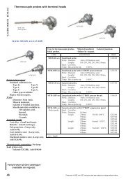


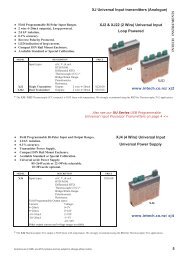
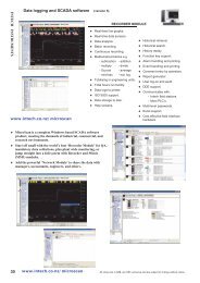

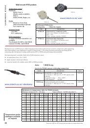
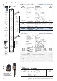


![NZ Catalogue Pages [PDF] - Intech Instruments Ltd](https://img.yumpu.com/36229536/1/184x260/nz-catalogue-pages-pdf-intech-instruments-ltd.jpg?quality=85)