Download 2100-A16 Installation Guide - Intech Instruments Ltd
Download 2100-A16 Installation Guide - Intech Instruments Ltd
Download 2100-A16 Installation Guide - Intech Instruments Ltd

You also want an ePaper? Increase the reach of your titles
YUMPU automatically turns print PDFs into web optimized ePapers that Google loves.
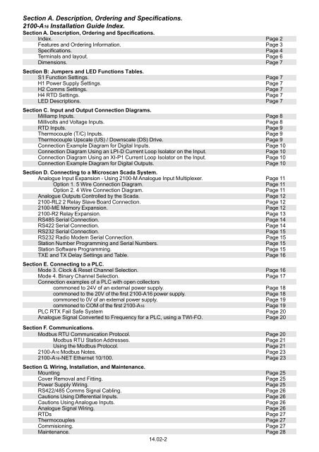
Section A. Description, Ordering and Specifications.<br />
<strong>2100</strong>-<strong>A16</strong> <strong>Installation</strong> <strong>Guide</strong> Index.<br />
Section A. Description, Ordering and Specifications.<br />
Index. Page 2<br />
Features and Ordering Information. Page 3<br />
Specifications. Page 4<br />
Terminals and layout. Page 6<br />
Dimensions. Page 7<br />
Section B: Jumpers and LED Functions Tables.<br />
S1 Function Settings. Page 7<br />
H1 Power Supply Settings. Page 7<br />
H2 Comms Settings. Page 7<br />
H4 RTD Settings. Page 7<br />
LED Descriptions. Page 7<br />
Section C. Input and Output Connection Diagrams.<br />
Milliamp Inputs. Page 8<br />
Millivolts and Voltage Inputs. Page 8<br />
RTD Inputs. Page 9<br />
Thermocouple (T/C) Inputs. Page 9<br />
Thermocouple Upscale (US) / Downscale (DS) Drive. Page 9<br />
Connection Example Diagram for Digital Inputs. Page 10<br />
Connection Diagram Using an LPI-D Current Loop Isolator on the Input. Page 10<br />
Connection Diagram Using an XI-P1 Current Loop Isolator on the Input. Page 10<br />
Connection Example Diagram for Digital Outputs. Page 10<br />
Section D. Connecting to a Microscan Scada System.<br />
Analogue Input Expansion - Using <strong>2100</strong>-M Analogue Input Multiplexer. Page 11<br />
Option 1. 5 Wire Connection Diagram. Page 11<br />
Option 2. 4 Wire Connection Diagram. Page 11<br />
Analogue Outputs Controlled by the Scada. Page 12<br />
<strong>2100</strong>-RL2 2 Relay Slave Board Connection. Page 12<br />
<strong>2100</strong>-ME Memory Expansion. Page 12<br />
<strong>2100</strong>-R2 Relay Expansion. Page 13<br />
RS485 Serial Connection. Page 14<br />
RS422 Serial Connection. Page 14<br />
RS232 Serial Connection. Page 15<br />
RS232 Radio Modem Serial Connection. Page 15<br />
Station Number Programming and Serial Numbers. Page 15<br />
Station Software Programming. Page 15<br />
TXE and TX Delay Settings and Table. Page 16<br />
Section E. Connecting to a PLC.<br />
Mode 3. Clock & Reset Channel Selection. Page 16<br />
Mode 4. Binary Channel Selection. Page 17<br />
Connection examples of a PLC with open collectors<br />
commoned to 24V of an external power supply. Page 18<br />
commoned to the 20V of the first <strong>2100</strong>-<strong>A16</strong> power supply. Page 18<br />
commoned to 0V of an external power supply. Page 19<br />
commoned to COM of the first <strong>2100</strong>-<strong>A16</strong> Page 19<br />
PLC RTX Fail Safe System Page 20<br />
Analogue Signal Converted to Frequency for a PLC, using a TWI-FO. Page 20<br />
Section F. Communications.<br />
Modbus RTU Communication Protocol. Page 20<br />
Modbus RTU Station Addresses. Page 21<br />
Using the Modbus Protocol. Page 21<br />
<strong>2100</strong>-<strong>A16</strong> Modbus Notes. Page 23<br />
<strong>2100</strong>-<strong>A16</strong>-NET Ethernet 10/100. Page 23<br />
Section G. Wiring, <strong>Installation</strong>, and Maintenance.<br />
Mounting Page 25<br />
Cover Removal and Fitting. Page 25<br />
Power Supply Wiring. Page 25<br />
RS422/485 Comms Signal Cabling. Page 26<br />
Cautions Using Differential Inputs. Page 26<br />
Cautions Using Analogue Inputs. Page 26<br />
Analogue Signal Wiring. Page 26<br />
RTDs Page 27<br />
Thermocouples Page 27<br />
Commisioning. Page 27<br />
Maintenance. Page 28<br />
14.02-2


![NZ Catalogue Pages [PDF] - Intech Instruments Ltd](https://img.yumpu.com/36229536/1/184x260/nz-catalogue-pages-pdf-intech-instruments-ltd.jpg?quality=85)