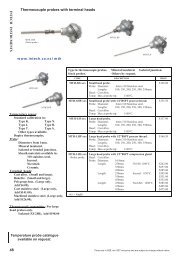
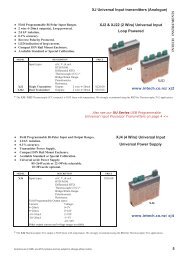
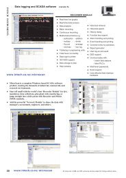
Download 2100-A16 Installation Guide - Intech Instruments Ltd
Download 2100-A16 Installation Guide - Intech Instruments Ltd
Download 2100-A16 Installation Guide - Intech Instruments Ltd

Create successful ePaper yourself
Turn your PDF publications into a flip-book with our unique Google optimized e-Paper software.
<strong>2100</strong>-<strong>A16</strong> Rev1.3 Relay Output Expansion - Using <strong>2100</strong>-R2 Relay Expansion.<br />
Output relay expansion is available using the <strong>2100</strong>-R2, 16 relay output expansion module. This allows the <strong>2100</strong>-<strong>A16</strong> to<br />
stand alone as a 16 channel controller / alarm unit. The <strong>2100</strong>-R2 relay outputs can be used for any combination of<br />
control and alarm functions. The control parameters for each of the 16 controllers is downloaded from user friendly<br />
Microscan Software, and stored in permanent memory on the <strong>2100</strong>-<strong>A16</strong>. These parameters include Setpoint (SV),<br />
Output Switching Differential, Auto / Manual, Manual Output Setting, Dual Action Control, Single Action Control, Heat /<br />
Cool, Heat Only, Cool Only. The 16 controller / alarms will operate unaffected by computer power downs, reboots, etc.<br />
The relay outputs can also be accessed directly from the Scada.<br />
<strong>2100</strong>-R2 Relay Expander<br />
Serial No.<br />
H3 2ND<br />
<strong>2100</strong>-R2<br />
H2 <strong>A16</strong><br />
Interface<br />
<strong>2100</strong>-ARI<br />
FIRST <strong>2100</strong>-R2<br />
.<br />
<strong>2100</strong>-<strong>A16</strong>-R1.3<br />
.<br />
WARNING: The <strong>2100</strong>-ARI is STATIC SENSITIVE.<br />
Only touch the edges of the PCB.<br />
Ensure standoffs lock firmly into the <strong>2100</strong>-<strong>A16</strong> board.<br />
<strong>2100</strong>-R2 Relay Expander<br />
Serial No.<br />
H3 2ND<br />
<strong>2100</strong>-R2<br />
H2 <strong>A16</strong><br />
Interface<br />
SECOND <strong>2100</strong>-R2<br />
Connecting the <strong>2100</strong>-<strong>A16</strong> to the <strong>2100</strong>-R2.<br />
1/ Power must be off before installing the 10 way ribbon cable and <strong>2100</strong>-ARI board<br />
supplied with the <strong>2100</strong>-R2.<br />
2/ Remove the cover off the <strong>2100</strong>-<strong>A16</strong>.<br />
3/ An exchange cover, with a precut slot for the ribbon cable, is available free of<br />
charge from your supplier. P/N: <strong>2100</strong>-<strong>A16</strong>-COVERSLOT.<br />
1x20mm<br />
Alternatively you may wish to modify the existing cover:<br />
SLOT<br />
Cut a 1mm slot, 20mm deep, just below terminal numbers 1, 2 & 3.<br />
Carefully smooth the edges of the cut so the ribbon cable does not get damaged.<br />
4/ The <strong>2100</strong>-ARI is supplied with the ribbon cable attached. Use antistatic precautions<br />
when installing. Carefully orientate the <strong>2100</strong>-ARI board as shown above. Locate the<br />
two plastic standoffs over the corresponding holes in the <strong>2100</strong>-<strong>A16</strong>, and the 10 pin<br />
connector. Once all three are aligned, push the <strong>2100</strong>-ARI firmly into the <strong>2100</strong>-<strong>A16</strong>.<br />
INPUT 1<br />
A B B<br />
INPUT 2<br />
A B B<br />
1 2 3 4 5 6<br />
5/ Connect the other end of the cable to the <strong>2100</strong>-R2. Ensure both ends of the cable are firmly connected.<br />
6/ Slide the cable into the slot, and replace the cover on the <strong>2100</strong>-<strong>A16</strong>.<br />
7/ The <strong>2100</strong>-R2 must be enabled in the programming dialogue boxes. Advanced ‘<strong>2100</strong>-R 2 Relay Expander’ options.<br />
For detailed programming info, refer to<br />
‘Programming <strong>2100</strong>-Series Remote Station’ in the Microscan Manual.<br />
8/ A <strong>2100</strong>-R2 connected to the <strong>2100</strong>-<strong>A16</strong> must share the same power supply disconnect device and over current<br />
device. Both units must be powered and unpowered at the same time to prevent indeterminate relay states.<br />
14.02-13


![NZ Catalogue Pages [PDF] - Intech Instruments Ltd](https://img.yumpu.com/36229536/1/184x260/nz-catalogue-pages-pdf-intech-instruments-ltd.jpg?quality=85)