Download 2100-A16 Installation Guide - Intech Instruments Ltd
Download 2100-A16 Installation Guide - Intech Instruments Ltd
Download 2100-A16 Installation Guide - Intech Instruments Ltd

You also want an ePaper? Increase the reach of your titles
YUMPU automatically turns print PDFs into web optimized ePapers that Google loves.
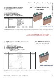
<strong>2100</strong>-<strong>A16</strong> RS232 Serial Connection.<br />
The <strong>2100</strong>-<strong>A16</strong> with RS232 comes complete with:<br />
• 1 x 5m RJ11 RS232 Cable. (2, 10 & 15m available.)<br />
• 1 x 9 Pin D-type Connector. (25 pin D-type available.)<br />
• USB to RS232 convertor available. Part No. BF-810.<br />
Location of RJ11 Socket on <strong>2100</strong>-<strong>A16</strong> Series.<br />
H<br />
M<br />
L<br />
Ph N E<br />
10VA<br />
50/60Hz<br />
85~264Vac/dc<br />
23~90Vdc<br />
10~28Vac/dc<br />
COMMS<br />
RS232<br />
RS422<br />
RS485<br />
RS422/RS485 COMMS<br />
COM TX TX RX RX<br />
COMMS Pinout Table<br />
RJ11<br />
DB9<br />
DB25<br />
1:RTS<br />
8 5<br />
2:GND<br />
5 7<br />
3:TX<br />
2 3<br />
4:CTS<br />
7 4<br />
5:n/c<br />
1 1<br />
6:RX<br />
3 2<br />
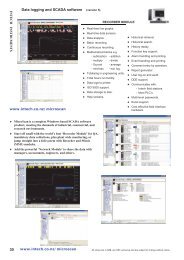
RS232 COMMS Hardware.<br />
Do Not cut RS232 Cable<br />
to extend the length.<br />
82 81 80 74 73 72 71 70 49 48 47<br />
RS232 RJ11 Socket<br />
<strong>Installation</strong>.<br />
Plug one end of the RS232 Comms cable into the RS232 RJ11<br />
Socket on the <strong>2100</strong> Module. Plug the other end into either the 9 or<br />
25 pin D-type connector. (Check for the correct D-type connector<br />
on the computer (or Omron PLC) RS232 port being used.) For<br />
further software and hardware information, Refer to the Microscan<br />
Manual ‘Programming the <strong>2100</strong> Series Remote Station.’<br />
<strong>2100</strong>-RS232 Kit-Omron<br />
RS232 Kit for Omron PLC. Includes 2m cable & 9 pin D-type connector.<br />
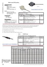
<strong>2100</strong>-<strong>A16</strong> RS232 Radio Modem Serial Connection.<br />
Note: The ‘<strong>2100</strong>-RS232-Radio’ 9 pin D connector differs from the<br />
<strong>2100</strong>-RS232 9 pin D supplied, and must be ordered separately.<br />
It can be exchanged at no charge for the 9 pin and 25 pin D<br />
connectors supplied with the <strong>2100</strong>-RS232 Remote Station.<br />
1. Refer to <strong>Installation</strong> paragraph above.<br />
2. Fit the ‘<strong>2100</strong>-RS232-Radio’ 9 pin D connector between the<br />
Radio end of the RS232 comms cable, and the Radio. This<br />
connector will work with most types of radio, but this is not<br />
guaranteed. Pin2=TX; Pin3=RX; Pin5=GND; Pin7=RTS.<br />
3. Refer to ‘H2 Comms Settings.’ to jumper as per RS232 Radio.<br />
4. Refer to radio manual for hardware handshaking settings for TX control. TXE & TX delay may need to be altered<br />
in the Scada Station Advanced Dialog box to suit the radio. Best case TX speed is one transmission per second.<br />
(Depends on Radio.) Default settings are: TXE = 25ms; TX = 0ms.<br />
5. If using more than one station at a remote radio site, <strong>2100</strong>-RS422 Remote Stations with a <strong>2100</strong>-IS with an adaptor<br />
kit must be used. (Do not use <strong>2100</strong>-RS485.) Refer to <strong>2100</strong>-IS installation <strong>Guide</strong>.<br />
<strong>2100</strong>-<strong>A16</strong> Station Number Programming and Serial Number.<br />
Important: When commissioning remote stations, you must programme a unique station number before using the<br />
programme setup button in the Scada Software. Requires Microscan Version 4.02 onwards.<br />
For detailed programming info, refer to ‘Programming <strong>2100</strong>-Series Remote Station’ in the Microscan Manual.<br />
1. Close the Microscan Scada down and turn the power off to the <strong>2100</strong> 422/485 converter. Connect the new Remote<br />
Station, referring to ‘Wiring and <strong>Installation</strong>’ and ‘Commissioning’<br />
2. Turn power back on to the <strong>2100</strong> 422/485 converter, and start the ‘Setup Manager’ in the Microscan Scada.<br />
3. Select ‘Recorder Setup’, or ‘Tag Setup’.<br />
4. Select ’Program Address’. (Located in ‘Station Programming Panel’, at the bottom right of the window.<br />
5. Enter the <strong>2100</strong>-<strong>A16</strong> serial number. (Written both on the <strong>2100</strong>-<strong>A16</strong> cover and the circuit board behind the power<br />
supply terminals. 80, 81 & 82. If the cover has been removed, the number on the circuit board is always correct.<br />
Replace with the correct cover to avoid future confusion.) Then enter the desired station number.<br />
6. Select ‘Program’. The station number will now be stored in <strong>2100</strong>-<strong>A16</strong> permanent memory.<br />
7. A new station number will be created on the outstation map. This is ready for connection to tags or lines.<br />
8. Restart the Microscan Scada.<br />
<strong>2100</strong>-<strong>A16</strong> Station Software Programming.<br />
*Requires Microscan Version 4.02 onwards.<br />
1. If the system is already running, close the Scada down. Start the ‘Setup Manager’.<br />
2. Select ‘Recorder Setup’, or ‘Tag Setup’.<br />
3. Move to the required station number, using ‘next’ or ‘prev’ buttons.<br />
4. Select ‘Program Setup’. The serial number of the <strong>2100</strong>-<strong>A16</strong> will be recalled automatically. The software recalls<br />
the settings from the outstation, and displays them in the dialogue box.<br />
5. Enter the required options and select ‘Program’ to write the data to the station.<br />
14.02-15<br />
<strong>2100</strong>-RS232<br />
Remote station.<br />
RS232<br />
Radio<br />
‘<strong>2100</strong>-RS232-Radio’<br />
9 pin D-type connector.


![NZ Catalogue Pages [PDF] - Intech Instruments Ltd](https://img.yumpu.com/36229536/1/184x260/nz-catalogue-pages-pdf-intech-instruments-ltd.jpg?quality=85)