Balloon - FOIA and eLibrary website! - NASA
Balloon - FOIA and eLibrary website! - NASA
Balloon - FOIA and eLibrary website! - NASA
- No tags were found...
You also want an ePaper? Increase the reach of your titles
YUMPU automatically turns print PDFs into web optimized ePapers that Google loves.
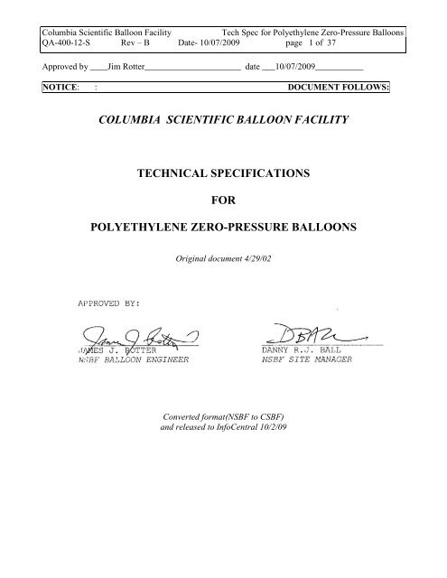
Columbia Scientific <strong>Balloon</strong> Facility<br />
Tech Spec for Polyethylene Zero-Pressure <strong>Balloon</strong>s<br />
QA-400-12-S Rev – B Date- 10/07/2009 page 1 of 37<br />
Approved by ____Jim Rotter______________________ date ___10/07/2009___________<br />
NOTICE: : DOCUMENT FOLLOWS:<br />
COLUMBIA SCIENTIFIC BALLOON FACILITY<br />
TECHNICAL SPECIFICATIONS<br />
FOR<br />
POLYETHYLENE ZERO-PRESSURE BALLOONS<br />
Original document 4/29/02<br />
Converted format(NSBF to CSBF)<br />
<strong>and</strong> released to InfoCentral 10/2/09
Columbia Scientific <strong>Balloon</strong> Facility<br />
Tech Spec for Polyethylene Zero-Pressure <strong>Balloon</strong>s<br />
QA-400-12-S Rev – B Date- 10/07/2009 page 2 of 37<br />
TABLE OF CONTENTS<br />
Page<br />
1. INTRODUCTION ............................................ 5<br />
1.1 Scope .............................................. 5<br />
1.2 Background ......................................... 5<br />
1.3 Deviations / Waivers ............................... 5<br />
2. MATERIALS ................................................ 6<br />
2.1 Film ................................................ 6<br />
2.1.1 Shell Film ................................... 6<br />
2.1.2 Other Film ................................... 7<br />
2.1.3 Shell PLI .................................. 7<br />
2.2 Load Tapes .......................................... 7<br />
2.3 Repair <strong>and</strong> Reinforcement Tapes ...................... 7<br />
2.3.1 Poly Tape .................................... 7<br />
2.3.2 Fiber-Reinforced Tape ........................ 7<br />
2.4 Electrical Cables .................................. 8<br />
2.4.1 Valve Cable ................................. 8<br />
2.4.2 LDB Cable & Connectors ....................... 8<br />
2.5 End Fittings ........................................ 8<br />
2.5.1 Base Fittings ................................ 8<br />
2.5.2 Apex Fittings ............................... 9<br />
2.5.3 End Fitting Paint ........................... 9<br />
3. BALLOON DESIGN .......................................... 10<br />
3.1 Design Philosophy .................................. 10<br />
3.1.1 Design Shape ................................ 10<br />
3.1.2 Design Thickness ............................ 10<br />
3.1.3 Procurement Methods ......................... ` 10
Columbia Scientific <strong>Balloon</strong> Facility<br />
Tech Spec for Polyethylene Zero-Pressure <strong>Balloon</strong>s<br />
QA-400-12-S Rev – B Date- 10/07/2009 page 3 of 37<br />
3.2 Design Nomenclature ................................ 11<br />
3.2.1 System of Units ............................ 11<br />
3.2.2 CSBF Identifier ............................. 11<br />
3.2.3 Definitions of Acronyms & Symbols ........... 12<br />
3.2.4 Measurements from Apex or Base .............. 13<br />
3.2.5 Altitude Reporting .......................... 13<br />
3.2.6 Specification Sheet ......................... 13<br />
3.3 <strong>Balloon</strong> Component Selection/Design Criteria ........ 14<br />
3.3.1 Total Film Thickness (per Launch Stress Index) 14<br />
3.3.2 Cap Location ................................ 14<br />
3.3.3 Shell/Cap Thickness (per Ascent Stress Index). 14<br />
3.3.4 Cap Lengths ................................. 15<br />
3.3.5 Load Tape Rating ............................ 15<br />
3.3.6 Base Gore Width for Tapeless <strong>Balloon</strong>s ....... 16<br />
3.3.7 Vent Ducts .................................. 16<br />
3.3.8 Inflation Tubes ............................. 16<br />
3.3.9 Destruct Device ............................. 17<br />
3.3.10 Reefing Sleeve .............................. 18<br />
3.3.11 Valve Cable ................................. 18<br />
3.3.12 Valve Ports ................................. 18<br />
4. BALLOON MARKINGS & PACKAGING ............................ 19<br />
4.1 Bubble Mark Locations ............................. 19<br />
4.2 <strong>Balloon</strong> Markings ................................... 19<br />
4.3 <strong>Balloon</strong> Packaging & Marking ........................ 20<br />
4.4 Shipping Container & Markings ...................... 20<br />
4.4.1 Folding & Box Configuration ................. 21<br />
4.4.2 Box Markings ............................... 21<br />
4.4.3 Attached Spec Sheets ........................ 22<br />
5. CONSTRUCTION & QUALITY CONTROL .......................... 22<br />
5.1 Manufacturer’s Procedures & Specifications ......... 22<br />
5.2 Sealing Specifications ............................. 23<br />
5.3 Film Usage Requirements ............................ 23<br />
5.4 Policy for CSBF QA Oversight ....................... 23<br />
5.4.1 QA Surveillance ............................. 23<br />
5.4.2 QA Audits ................................... 25
Columbia Scientific <strong>Balloon</strong> Facility<br />
Tech Spec for Polyethylene Zero-Pressure <strong>Balloon</strong>s<br />
QA-400-12-S Rev – B Date- 10/07/2009 page 4 of 37<br />
6. DOCUMENTATION .......................................... 25<br />
7. REVISION RECORD ......................................... 27<br />
REFERENCES ................................................... 28<br />
APPENDIX<br />
A<br />
B<br />
C<br />
D<br />
E<br />
LDB BALLOON WIRING SCHEMATIC<br />
BALLOON SPECIFICATION SHEET WITH INSTRUCTIONS<br />
ASCENT STRESS INDEX - DERIVATION / EXPLANATION<br />
BALLOON BOXING & LABELING CONFIGURATION DRAWINGS<br />
QUALITY ASSURANCE BALLOON SECTION AUDIT PLAN
Columbia Scientific <strong>Balloon</strong> Facility<br />
Tech Spec for Polyethylene Zero-Pressure <strong>Balloon</strong>s<br />
QA-400-12-S Rev – B Date- 10/07/2009 page 5 of 37<br />
1.0 INTRODUCTION<br />
1.1 SCOPE<br />
This specification covers the technical requirements for polyethylene zero-pressure balloons purchased<br />
by CSBF. Other types of balloons, e.g. sounding balloons, superpressure balloons, <strong>and</strong> tow balloons<br />
will be covered separately. These requirements for materials, design, construction, QA/QC, marking,<br />
reporting, <strong>and</strong> packaging must be met or agreed to by the vendor for a proposal to be considered<br />
responsive.<br />
1.2 BACKGROUND<br />
All offerers must have their production procedures <strong>and</strong> QC program previously approved by <strong>NASA</strong><br />
<strong>and</strong> CSBF (<strong>Balloon</strong> Engineer <strong>and</strong> QA). This is accomplished by presenting the program <strong>and</strong><br />
documentation to CSBF for review <strong>and</strong> by verification with ground tests <strong>and</strong> qualification test flights.<br />
This specification replaces <strong>and</strong> supersedes CSBF's "Technical Specifications for Polyethylene Zero-<br />
Pressure <strong>Balloon</strong>s", dated April 1980. Due to the length of CSBF's specifications, CSBF will not send<br />
a copy with every RFP. CSBF will supply a current copy for the balloon vendors to keep on file for<br />
reference. This includes the other CSBF specifications referenced in this document, viz. film<br />
specifications (Ref.’s 1 & 2) <strong>and</strong> sealing specifications (Ref. 4). Proposals with balloon designs which<br />
come the closest to matching these specifications while being on the conservative side, will be<br />
considered technically most efficient.<br />
Major changes in this revision to the specifications include:<br />
(1) New designs are to be designed with the fully deployed (design) shape at the Maximum<br />
Recommended Payload rather than at the minimum. (CSBF will however retain the<br />
option to order designs produced with alternate methods).<br />
(2) The Launch Stress Index (LSI) limit, which is used for setting the total film thickness of<br />
the launch bubble, has been increased from 1400 PSI to 1800 PSI. Similarly, the<br />
Ascent Stress Index (ASI) limit has been increased from 2750 PSI to 3800 PSI.<br />
(3) The st<strong>and</strong>ard cap location is now external rather than internal to the balloon wall.<br />
These changes were previously incorporated into the <strong>NASA</strong> St<strong>and</strong>ard Design Array of balloons in<br />
1992 (‘92 SDA).<br />
1.3 DEVIATIONS / WAIVERS<br />
The supplier is urged to avoid or correct deviations from these specifications if at all possible,<br />
particularly if they may in any way adversely affect the performance of the balloon. Provision is made<br />
for the possibility of waivers in special cases which are not deemed detrimental. Long-term proposed<br />
vendor exceptions to this specification must be requested by the vendor <strong>and</strong> approved in writing by the
Columbia Scientific <strong>Balloon</strong> Facility<br />
Tech Spec for Polyethylene Zero-Pressure <strong>Balloon</strong>s<br />
QA-400-12-S Rev – B Date- 10/07/2009 page 6 of 37<br />
CSBF <strong>Balloon</strong> Engineer <strong>and</strong> the Site Manager <strong>and</strong> be on file at CSBF before a purchase order will be<br />
issued. Individual proposed vendor exceptions to this specification must be pointed out by the vendor<br />
in their proposal <strong>and</strong> approved by the CSBF <strong>Balloon</strong> Engineer in the normal procurement process.<br />
A balloon delivered with an unapproved deviation from these specifications will not be accepted unless<br />
the vendor first applies for a waiver in writing <strong>and</strong> obtains approval from the CSBF <strong>Balloon</strong> Engineer.<br />
The waiver must: cite the passage of the specification which was violated, give a precise description<br />
of the deviation, explain why the manufacturer believes it will not be detrimental to the performance of<br />
the balloon, <strong>and</strong> note any corrective actions planned to prevent reoccurrence of the problem.<br />
It is m<strong>and</strong>atory that CSBF be kept informed in a timely manner of significant changes in the balloon<br />
materials or production processes, etc., in order that this may be noted in the CSBF flight record. The<br />
exact nature of the change is not required. Seemingly minor changes may be significant under the<br />
conditions encountered by a balloon in flight.<br />
2.0 MATERIALS<br />
2.1 FILM<br />
All balloon film (shell, cap, inflation tube, duct, seal buffer tape, load tape substrate, reefing sleeve,<br />
<strong>and</strong> valve cable sheaths, etc.) must be polyethylene, fully identified as to manufacturer, film type, <strong>and</strong><br />
date of production, <strong>and</strong> be traceable to balloon production.<br />
2.1.1 SHELL FILM<br />
The film type to be used for the balloon shell (wall), caps, <strong>and</strong> ducts must be <strong>NASA</strong> Qualified. There<br />
are currently two <strong>NASA</strong> Qualified balloon film types as listed below with their applicable<br />
specifications:<br />
0.8 MIL WINZEN STRATOFILM-372:<br />
"CSBF SPECIFICATIONS FOR WINZEN STRATOFILM-372 0.8 MIL BALLOON FILM",<br />
dated 2/16/94.<br />
0.8 MIL RAVEN ASTROFILM-E2:<br />
"CSBF SPECIFICATIONS FOR RAVEN ASTROFILM-E2 0.8 MIL BALLOON FILM", dated<br />
4/30/92.<br />
Only <strong>NASA</strong>-Certified film may be used in the shell, caps, <strong>and</strong> ducts of CSBF balloons. This will be<br />
accomplished by submitting Roll # Lists <strong>and</strong> the required QC test data to CSBF QA for certification in<br />
accordance with the above listed applicable film specifications.
Columbia Scientific <strong>Balloon</strong> Facility<br />
Tech Spec for Polyethylene Zero-Pressure <strong>Balloon</strong>s<br />
QA-400-12-S Rev – B Date- 10/07/2009 page 7 of 37<br />
2.1.2 OTHER FILM<br />
For the other gauges of film not covered under the above listed specifications, the balloon offerers<br />
shall maintain in-house production <strong>and</strong> QC procedures with acceptance criteria which are available to<br />
<strong>and</strong> subject to CSBF approval. These other gauges of film shall be made from the same resin <strong>and</strong> be of<br />
the same general quality as the shell/cap film.<br />
2.1.3 SHELL PLI<br />
All rolls of film to be used as shell material must pass cross-polarized light inspection (PLI). The<br />
manufacturer shall maintain an in-house flaw catalogue, PLI procedures, <strong>and</strong> PLI operator training<br />
procedures which ensure that all serious flaws (e.g. holes, slits, severe scratches, severe abrasions,<br />
severe stretch marks, <strong>and</strong> hard gels) are marked <strong>and</strong> repaired. During PLI each flaw shall be marked<br />
appropriately with a red marker, <strong>and</strong> a mark shall be placed on the slit edge of the roll of film to aid the<br />
fabrication crew in locating the flaw. Rolls with serious, chronic flaws shall be rejected. An<br />
individual PLI record sheet shall be kept for each roll inspected. It shall identify the inspector, date of<br />
inspection, all flaws noted during the inspection, <strong>and</strong> the final disposition of the roll of film.<br />
2.2 LOAD TAPES<br />
Load bearing tapes will be rated as ≤90% of the breaking load with that load applied linearly at a<br />
constant loading rate of 100 ± 20 LB/SEC. Substrate materials must meet the requirements stated in<br />
the film section (2.1) of this specification or be extruded from the same resin. Fibers used to form the<br />
load members must have a published brittle transition temperature outside of the range -80°C to 65°C.<br />
The radar reflective yarn to be used in the load tapes should be Lundy Yarn #100/200 with a<br />
reflectivity of 200 to 2700 MHz (or an CSBF-approved equivalent).<br />
Load tape fabrication techniques using adhesives are discouraged. If the substrate layers are to be<br />
bonded together using adhesives, then the manufacturer must first establish a blocking test <strong>and</strong><br />
acceptance procedure with CSBF approval.<br />
2.3 REPAIR & REINFORCEMENT TAPES<br />
2.3.1 POLY TAPE<br />
"Poly Tape" to be used for repair <strong>and</strong> reinforcement of the balloon will be Raven Industries, Inc. (RII)<br />
pressure sensitive polyethylene balloon tape, SSA-10.<br />
2.3.2 FIBER-REINFORCED TAPE<br />
Fiber-Reinforced Tape to be used for reinforcement of the balloon will be 3M Company pressure<br />
sensitive fiber-reinforced tape, # 890.
Columbia Scientific <strong>Balloon</strong> Facility<br />
Tech Spec for Polyethylene Zero-Pressure <strong>Balloon</strong>s<br />
QA-400-12-S Rev – B Date- 10/07/2009 page 8 of 37<br />
2.4 ELECTRICAL CABLES<br />
2.4.1 VALVE CABLE & CONNECTORS<br />
Electrical cables supplied in valve cable assemblies, etc., must be Berkshire Electric Cable Co.<br />
str<strong>and</strong>ed, tinned copper conductor wire with white untreated double cellulose acetate braid insulation.<br />
Only st<strong>and</strong>ard American Wire Gauges are to be used. All wires installed in the balloon must be<br />
continuous lengths, i.e. splice-free from end to end.<br />
A st<strong>and</strong>ard CSBF valve cable consists of four (4) #16-AWG wires. A four-wire socket connector, #<br />
MS3106A-14S-2S, will be installed on the apex end of the cable. A four-wire pin connector, #<br />
MS3101A-14S-2P, with pull-away, will be installed at the base.<br />
2.4.2 LDB CABLE & CONNECTORS<br />
<strong>Balloon</strong>s ordered with st<strong>and</strong>ard LDB requirements require additional cable in the valve cable sheath.<br />
This cable is to consist of two (2) shielded twisted pair cables with continuous (un-spliced) lengths.<br />
Each twisted pair cable is specified as follows:<br />
Two conductor 24 Gauge with white Teflon tape or extrusion outer jacket. Belden 83318 or<br />
Thermax 24-TE-1936 (2) STJ or Philadelphia Insulated Wire Co. 102-219-T2 or equivalent.<br />
The LDB cables require 5-Pin Amphenol type connectors with pull-away at the base of the balloon.<br />
Connector Pins A & B - Pair 1, Pins C & D - Pair 2, <strong>and</strong> both pairs shields wired to Pin E (see<br />
drawing, Appendix A). Connector specifications are as follows:<br />
<strong>Balloon</strong> Apex Connector: Amphenol MS3106A-14S-5S<br />
with: Amphenol 97-3057-6 Backshell<br />
<strong>Balloon</strong> Base Connector: Amphenol MS3101A-14S-5P (pull-away)<br />
with: Amphenol 97-3057-6 Backshell<br />
2.5 END FITTINGS<br />
2.5.1 BASE FITTINGS<br />
Since the main threaded fasteners in the base fitting are potential single point failure items in the flight<br />
system, they are subject to the <strong>NASA</strong>/GSFC policy for structural threaded fasteners for flight<br />
hardware. Traceable certifications of the strengths of all eye bolts <strong>and</strong> eyenuts are required. The<br />
certifications must state the ultimate strength or working load limit <strong>and</strong> associated factor of safety.<br />
Traceable certifications of the minimum mechanical properties, i.e., yield <strong>and</strong> ultimate tensile strength<br />
of the threaded studs <strong>and</strong> wedges, are required. A stress analysis providing the minimum ultimate
Columbia Scientific <strong>Balloon</strong> Facility<br />
Tech Spec for Polyethylene Zero-Pressure <strong>Balloon</strong>s<br />
QA-400-12-S Rev – B Date- 10/07/2009 page 9 of 37<br />
strength of the threaded stud/wedge interface is required for each type of base fitting. A quality control<br />
(QC) traceability system is required for all load-bearing, threaded, base fitting components, either new<br />
or used. This system must be presented to <strong>and</strong> approved by the CSBF Quality Assurance (QA)<br />
Manager.<br />
2.5.2 APEX FITTINGS<br />
Aluminum plate used for the plate, hoop <strong>and</strong> clamp ring end fittings shall be degreased 6061-T6. All<br />
plate, hoop <strong>and</strong> clamp end fittings shall have two h<strong>and</strong>les affixed to the plate. H<strong>and</strong>les on the valve<br />
cover ports are not acceptable.<br />
2.5.3 END FITTING PAINT<br />
All exposed exterior plate surfaces of apex fittings shall be spray painted with an CSBF-approved<br />
white paint. Paints currently approved include:<br />
- Sherwin-Williams "Controls Rust Spray Enamel, Gloss White" (1400522)<br />
- Krylon "Appliance Epoxy, White" (8036).<br />
The surfaces must be painted to within 0.25 inch of clamp ring gaskets or valve port gaskets.<br />
<strong>Balloon</strong>s ordered with st<strong>and</strong>ard LDB requirements require additional painting as follows:<br />
All exposed surfaces (both exterior & interior) of apex <strong>and</strong> base fittings are to be spray-painted with<br />
the st<strong>and</strong>ard white paint.
Columbia Scientific <strong>Balloon</strong> Facility<br />
Tech Spec for Polyethylene Zero-Pressure <strong>Balloon</strong>s<br />
QA-400-12-S Rev – B Date- 10/07/2009 page 10 of 37<br />
3.0 BALLOON DESIGN<br />
3.1 DESIGN PHILOSOPHY<br />
3.1.1 DESIGN SHAPE<br />
The design philosophy should be based upon the "Natural Shape" balloon design. Deviations from this<br />
basic concept due to manufacturers design practices or experience are to be noted in the cover letter of<br />
the proposal <strong>and</strong> the design spec sheet.<br />
New designs are to be designed with the fully deployed (design) shape at the Maximum Recommended<br />
Payload rather than at the minimum. (CSBF will however retain the option to order existing designs<br />
produced with alternate methods).<br />
3.1.2 DESIGN THICKNESS<br />
Two types of stress indexes are defined to give a relative measure of the magnitude of stresses in the<br />
balloon <strong>and</strong> to provide an analytical method for determining safe, consistent, <strong>and</strong> efficient thicknesses<br />
for different designs. The Launch Stress Index (LSI) limit is used to set the minimum required total<br />
thickness (shell + caps) at launch. The Ascent Stress Index (ASI) limit is used to set the minimum<br />
required shell thickness for flight.<br />
3.1.3 PROCUREMENT METHODS<br />
Quotations may be requested for specific model numbers or for specific requirements (e.g., volume or<br />
minimum altitude, maximum recommended payload, minimum recommended payload, gore length,<br />
special cap lengths, etc.). Any design feature specifically specified in a Request for Proposal (RFP)<br />
will take precedence over the applicable requirement in this specification. Most RFP's, however, will<br />
be presented based on nominal launch payload, initial float payload <strong>and</strong> altitude, <strong>and</strong> minimum float<br />
payload. The following equations will be used to establish design limits:<br />
Maximum Recommended Payload ≥ Nominal Launch Payload/0.8<br />
Minimum Recommended Payload ≤ Minimum Float Payload/1.2<br />
<strong>NASA</strong>/CSBF will normally maintain a set of <strong>NASA</strong> St<strong>and</strong>ard <strong>Balloon</strong> Designs for normal science<br />
needs for large balloons (Vol. ≥ 4 MCF). These designs will be developed in a special cooperative<br />
effort between <strong>NASA</strong>/CSBF <strong>and</strong> the supplier. Special procurement methods, e.g. blanket orders, may<br />
be set up to allow for the expedient procurement of these balloons.
Columbia Scientific <strong>Balloon</strong> Facility<br />
Tech Spec for Polyethylene Zero-Pressure <strong>Balloon</strong>s<br />
QA-400-12-S Rev – B Date- 10/07/2009 page 11 of 37<br />
3.2 DESIGN NOMENCLATURE<br />
3.2.1 SYSTEM OF UNITS<br />
The English System of Units (feet, inches, pounds, seconds, etc.) will be used for all specifications <strong>and</strong><br />
performance reporting for CSBF balloons.<br />
3.2.2 CSBF IDENTIFIER<br />
All balloon designs for CSBF will be given a design identifier of the format:<br />
MV-C<br />
Where:<br />
M - Manufacturer's (or Designer's) first initial.<br />
V - Inflated balloon volume in millions of cubic feet. (MCF) to four significant digits.<br />
(EX.: 29,470,000 is 29.47; 1500 is .0015)<br />
C - Number of caps.<br />
Each balloon produced for CSBF will then be given a CSBF Identifier which contains the design<br />
identifier plus unique sequence numbers assigned by the manufacturer <strong>and</strong> CSBF as follows:<br />
Where:<br />
(NNN) MV-C-SN<br />
NNN -<br />
SN -<br />
CSBF <strong>Balloon</strong> Number, a unique sequence number assigned to each<br />
balloon procured, or to be flown, by CSBF. (This number will be<br />
assigned by the CSBF <strong>Balloon</strong> Engineer just before production<br />
commences).<br />
Manufacturer's Serial Number, a unique sequence number assigned to<br />
each balloon of each type produced by the manufacturer.<br />
CSBF reserves the right to designate the Identifier to be used on all its balloons. New variables may be<br />
added to the balloon identifier when deemed necessary (e.g. "I" for internal caps or "E" for external<br />
caps). Examples of some actual CSBF <strong>Balloon</strong> Identifiers are as follows:<br />
(612) R11.62-1E-103 (611) W39.57-3-02<br />
(894) R4.00-1-21 (676) W.0029-0-07<br />
The CSBF Identifier shall be used by the manufacturer in all correspondence with CSBF <strong>and</strong> in the
Columbia Scientific <strong>Balloon</strong> Facility<br />
Tech Spec for Polyethylene Zero-Pressure <strong>Balloon</strong>s<br />
QA-400-12-S Rev – B Date- 10/07/2009 page 12 of 37<br />
heading of <strong>Balloon</strong> Spec Sheets to designate a design or a specific balloon. The CSBF Identifiers for<br />
the current set of <strong>NASA</strong> St<strong>and</strong>ard <strong>Balloon</strong> Designs are as follows:<br />
W11.82-1E, W11.82-3E, W29.47-2X,<br />
W39.57-2, W39.57-3<br />
3.2.3 DEFINITIONS OF ACRONYMS & SYMBOLS<br />
Acronyms <strong>and</strong> symbols used in the design equations are defined as follows:<br />
SYMBOL QUANTITY UNITS<br />
A Total Duct Area ft 2<br />
ASI Ascent Stress Index psi<br />
BGW Base Gore Width in<br />
BL Bubble Location ft<br />
BW <strong>Balloon</strong> Weight lb<br />
b Buoyancy lb/ft 3<br />
CL Cap Length ft<br />
D <strong>Balloon</strong> Diameter ft<br />
FL Free Lift lb<br />
FL mx Maximum Free Lift lb<br />
(0.12(P mx + BW))<br />
GI Gross Inflation lb<br />
GI mx Maximum Gross Inflation lb<br />
(1.12 (P mx + BW))<br />
GI n Nominal Gross Inflation lb<br />
(1.12 (P n + BW))<br />
L<br />
Distance from Apex<br />
to Inflation Tubes<br />
ft<br />
LSI Launch Stress Index psi<br />
MCF Million Cubic Feet 10 6 ft 3
Columbia Scientific <strong>Balloon</strong> Facility<br />
Tech Spec for Polyethylene Zero-Pressure <strong>Balloon</strong>s<br />
QA-400-12-S Rev – B Date- 10/07/2009 page 13 of 37<br />
NG Number of Gores –<br />
P mn Minimum Recommended Payload lb<br />
P mx Maximum Recommended Payload lb<br />
P n Nominal Payload lb<br />
r Radius from Axis of Symmetry ft<br />
TR Load Tape Rating lb<br />
t Total Film Thickness mil<br />
t s Shell Film Thickness mil<br />
V Inflated <strong>Balloon</strong> Volume MCF<br />
z<br />
Height above<br />
Zero-Pressure Line<br />
ft<br />
θ o Initial Wall Angle degrees<br />
3.2.4 MEASUREMENTS FROM APEX OR BASE<br />
In the phrase "from the apex", apex is taken to mean theoretical apex, i.e. the center of the apex fitting.<br />
In the phrase "from the base", base is taken to mean theoretical base, i.e. the point of intersection of the<br />
balloon center line <strong>and</strong> the projection of the gore line at the base.<br />
3.2.5 ALTITUDE REPORTING<br />
The st<strong>and</strong>ard for all altitude predictions will be Ref. 3, the NCAR Technical Note, TN/1A-69,<br />
"Aerostatic Lift of Helium <strong>and</strong> Hydrogen in the Atmosphere", which uses the U.S. St<strong>and</strong>ard<br />
Atmosphere, 1962. The st<strong>and</strong>ard lifting gas will be Helium, unless otherwise specified.<br />
A balloon performance sheet, “Load/Altitude Curve”, will be required for each balloon design. It will<br />
consist of balloon average float altitudes shown on a graph with geopotential altitude in feet for the<br />
ordinate <strong>and</strong> gross load (including balloon weight) in pounds for the abscissa. The graph title will<br />
contain the manufacturer, manufacturer’s model number, maximum <strong>and</strong> minimum recommended<br />
payloads, estimated balloon weight, <strong>and</strong> date drawn.
Columbia Scientific <strong>Balloon</strong> Facility<br />
Tech Spec for Polyethylene Zero-Pressure <strong>Balloon</strong>s<br />
QA-400-12-S Rev – B Date- 10/07/2009 page 14 of 37<br />
3.2.6 SPECIFICATION SHEET<br />
A st<strong>and</strong>ard specification sheet, “Spec Sheet”, will be required showing the balloon features. (See the<br />
st<strong>and</strong>ard format for the Spec Sheet in Appendix B). Modifications to this format must be pre-approved<br />
by the CSBF <strong>Balloon</strong> Engineer. A “Design Spec Sheet” will be required in the proposal process, <strong>and</strong><br />
an accurate "As-Built Spec Sheet” will be required for each balloon delivered.<br />
3.3 BALLOON COMPONENT SELECTION/DESIGN CRITERIA<br />
3.3.1 TOTAL FILM THICKNESS (PER LAUNCH STRESS INDEX)<br />
A simplified Launch Stress Index (LSI) is defined based on simplified assumptions to give a sphere<br />
stress for a spherical balloon (bubble) at launch as follows:<br />
LSI =<br />
(GI)2/3<br />
(. 1167)t<br />
The minimum required total film thickness (shell + caps) is then defined by putting an empirical limit<br />
on the LSI based on flight history. The LSI limit is currently set at 1800 psi, resulting in the following<br />
equation for total film thickness:<br />
t ≥ (GI mx) 2/3<br />
210<br />
The division of film thickness among the shell <strong>and</strong> caps is left to the discretion of the manufacturer,<br />
but of course the choice is limited to the <strong>NASA</strong>-Qualified balloon film types (only 0.8 MIL films are<br />
currently <strong>NASA</strong>-Qualified).<br />
3.3.2 CAP LOCATION<br />
The st<strong>and</strong>ard location for caps used to increase the total film thickness of the launch bubble is external<br />
to the balloon wall. Any deviation from this will be specified in the individual balloon order.<br />
3.3.3 SHELL/CAP THICKNESS (PER ASCENT STRESS INDEX)<br />
The Ascent Stress Index (ASI) accounts for the ascending balloon shape in the approximation of the<br />
maximum balloon stress (see derivation in Appendix C) <strong>and</strong> is defined as follows:<br />
ASI = b(rz) mx<br />
t
Columbia Scientific <strong>Balloon</strong> Facility<br />
Tech Spec for Polyethylene Zero-Pressure <strong>Balloon</strong>s<br />
QA-400-12-S Rev – B Date- 10/07/2009 page 15 of 37<br />
The ASI limit is currently set empirically at 3800 psi. The balloon's total film thickness in the capped<br />
region <strong>and</strong> the shell thickness below the caps must be thick enough so that throughout flight :<br />
ASI mx ≤ 3800 psi<br />
For designs with the st<strong>and</strong>ard external cap location, the caps remain effective throughout the flight <strong>and</strong><br />
are therefore included in the total film thickness in the capped region when computing ASI. For<br />
special designs with internal caps, the designer must take into account when the caps become<br />
ineffective to ensure that the ASI limit is not exceeded.<br />
3.3.4 CAP LENGTHS<br />
The length of the shortest cap must meet the following requirement:<br />
CL ≥ 7.862 (GI mx ) 1/3<br />
Additional caps must be a minimum of 15 ft longer than the previous cap. Caps may be spaced more if<br />
dictated by manufacturing requirements. The st<strong>and</strong>ard cap location is external to the balloon wall (on<br />
the outside of the balloon), unless specified otherwise. For multi-cap balloons, the shortest cap shall<br />
be adjacent to the balloon wall, <strong>and</strong> the longest cap shall be outermost from the balloon wall. For a<br />
st<strong>and</strong>ard external cap balloon, this puts the longest cap on the outside of the balloon.<br />
3.3.5 LOAD TAPE RATING<br />
The load rating required for load tapes will be determined as:<br />
TR ≥<br />
4<br />
NG [(P mx/COS θ 0 ) + BW + FL mx ]<br />
Unless otherwise specified, all balloons with load tapes will have radar reflective yarn in the load tapes<br />
(radar tapes) at the following frequency:<br />
VOLUME<br />
MCF<br />
> 12 Every Tenth Tape<br />
5-12 Every Fifth Tape<br />
2-5 Every Third Tape<br />
1-2 Every Other Tape<br />
0-1 Every Tape
Columbia Scientific <strong>Balloon</strong> Facility<br />
Tech Spec for Polyethylene Zero-Pressure <strong>Balloon</strong>s<br />
QA-400-12-S Rev – B Date- 10/07/2009 page 16 of 37<br />
To ease manufacturing, a small degree of variation is allowed in the distribution of the radar tapes as<br />
long as there is uniform distribution in the final product <strong>and</strong> the required total is met.<br />
3.3.6 BASE GORE WIDTH FOR TAPELESS BALLOONS<br />
The base gore width for tapeless balloons shall be determined from the following equation:<br />
3.3.7 VENT DUCTS<br />
BGW ≥ (P mx/ cos θ 0 ) + BW + FL mx<br />
(0.8)(NG)(t)<br />
The following equation will give the total area required of the vent ducts:<br />
A ≥ (2.76 × 10 −5 ) D 2 GI mx /t s<br />
Unless otherwise specified, there will be at least two duct tubes, but three or four are preferred.<br />
Horsetail or attached ducts will be specified in the order.<br />
The bottom of wall penetrations for ducts will be located between ¼ to ⅓ of the gore length from the<br />
base, rounded to the nearest even foot. The length of horsetail ducts will be such that the bottom of the<br />
duct is even with the base of the balloon when at float with the maximum recommended payload.<br />
Film thickness of the ducts will be the same as the balloon shell.<br />
3.3.8 INFLATION TUBES<br />
All balloons with V ≥ 0.1 MCF will have two inflation tubes, located 180° apart, so that they are<br />
perpendicular to the flight train during inflation.<br />
Thickness control requirements for inflation tube material are as follows:<br />
Gram Weight:<br />
Profile:<br />
t IT = 3 ± 0.18 mil<br />
t IT = 3 ± 1.2 mil<br />
St<strong>and</strong>ard inflation tube diameter will be as follows:<br />
D IT ≥ 9.5 in<br />
Manufacturers will specify <strong>and</strong> explain all deviations from these st<strong>and</strong>ards.<br />
Each inflation tube must be pressure tested, inspected for leaks or flaws, <strong>and</strong> approved by QC before<br />
installation.
Columbia Scientific <strong>Balloon</strong> Facility<br />
Tech Spec for Polyethylene Zero-Pressure <strong>Balloon</strong>s<br />
QA-400-12-S Rev – B Date- 10/07/2009 page 17 of 37<br />
The distance from the apex to the center of wall penetrations for inflation tubes will be determined<br />
from the following equation:<br />
L = 2.313 [. 8 P mx + BW] 1/3 ± 2<br />
There will be at least a 2 inch clearance between the edge of the inflation tube reinforcement <strong>and</strong> the<br />
gore seam. In some cases this will set the location from the apex.<br />
All <strong>NASA</strong> St<strong>and</strong>ard Design <strong>Balloon</strong>s without external caps shall have 0.8 mil external reinforcement<br />
sheets on the inflation tube gores. These external reinforcement sheets shall be the same shape as the<br />
gore, integrally sealed with the gore, <strong>and</strong> extending from the apex to five feet (5 ± 1 ft) above the<br />
shortest cap, or, for capless balloons, to five feet (5 ± 1 ft) less than the Cap Length Equation (Sect<br />
3.3.2).<br />
Inflation tubes will have continuous, visible green stripes 0.75 inches (0.75 ± 0.25") wide running the<br />
length of the tubes. The number of stripes will indicate the sequence of installation of the respective<br />
tubes, i.e., one stripe on the first tube installed, two stripes on the second, etc. The circumferential<br />
location of the stripes will be such that they appear on the upper side of the tube during inflation. The<br />
gore number on which the inflation tube is installed shall also be written on the inflation tube in 2 inch<br />
(2" ± 0.5") high red numerals placed within one foot of the point of its attachment to the balloon gore<br />
material. In the same manner, an "L" or "R" for the left or right side of the balloon stack (looking<br />
down the laid-out balloon from the apex toward the base) shall also be written just below the gore<br />
number to assist the launch crew in the location of the tubes. The tube number, gore number, <strong>and</strong> "L"<br />
or "R" shall also be recorded on the bag in which the inflation tube is folded in the packaged<br />
configuration.<br />
3.3.9 DESTRUCT DEVICE<br />
CSBF will evaluate destruct device designs for balloons with lightweight payloads (PL < 200 lb) on a<br />
proposal basis. All balloons with heavier payloads will have a top secured, rip panel, payload-actuated<br />
destruct device.<br />
The rip panel shall be positioned to rip a hole in the balloon such that the top of the hole is high enough<br />
on the balloon that the residual gas in an upright balloon would be insufficient to support the balloon<br />
weight at sea level. The detailed design of the rip panel <strong>and</strong> associated devices is left to the discretion<br />
of the manufacturer, <strong>and</strong> is subject to CSBF approval.<br />
The gore location of the rip panel <strong>and</strong> its two adjacent gores (& seams) shall not contain attachments of<br />
any other type, e.g. valve cables, vent ducts, inflation tubes, reefing sleeve seam, etc. This will help<br />
insure that these attachments are not destroyed by use of the destruct device, improving the chances of<br />
locating <strong>and</strong> checking these appendages in case of a study or failure investigation.<br />
The rip panel line shall be 1000 lb rated, white, braided nylon. It shall extend from the rip panel to be<br />
suspended from the apex by a breakaway device or line. The rip line will hang freely from the apex to<br />
the base, where it will pass through a suitable fitting, terminating at least 10 ft below the balloon. The<br />
breakaway device or line shall be strong enough to support at least three times the weight of the rip
Columbia Scientific <strong>Balloon</strong> Facility<br />
Tech Spec for Polyethylene Zero-Pressure <strong>Balloon</strong>s<br />
QA-400-12-S Rev – B Date- 10/07/2009 page 18 of 37<br />
panel line, but will release the rip line from the top end fitting when a force is applied through the rip<br />
panel line that is half the weight of the minimum recommended payload (Force = P mn /2). (In some<br />
cases, this requirement may fix the value of the minimum recommended payload).<br />
The rip panel line portion between the bottom of the balloon <strong>and</strong> the top end fitting shall have at least<br />
5% slack laid inside the balloon <strong>and</strong> evenly distributed along its length. The portion of the line from<br />
the top fitting to the rip panel shall have at least 10% slack. Care must be taken to avoid any<br />
possibility of entanglement of these two portions of the line in the folded/packaged balloon.<br />
3.3.10 REEFING SLEEVE<br />
All balloons with caps <strong>and</strong>/or a wall thickness less than 1 mil <strong>and</strong> an inflated volume greater than 1<br />
MCF will have a reefing sleeve to provide added protection during the launch phase.<br />
The sleeve will extend from the base of the balloon to 10 ft above the bottom of the shortest cap. The<br />
distance from the apex to the top of the sleeve for balloons without caps will be 10 ft less than the<br />
distance determined from the equation in paragraph 3.3.4 of this specification. (The top of the sleeve<br />
will normally be specified to be higher on the <strong>NASA</strong> St<strong>and</strong>ard Design <strong>Balloon</strong>s to h<strong>and</strong>le the wide<br />
payload ranges, but not higher than 10 ft below the maximum bubble mark).<br />
The sleeve shall be continuously sealed for its entire length to a flange which is sealed to a balloon<br />
gore seam. The reefing sleeve seal shall be reinforced with a single strip of poly tape on each side of<br />
the seal for 15 ft from the top of the seal.<br />
The thickness of the sleeve shall be determined by the manufacturer. A rip panel will be sealed into<br />
the sleeve for its entire length <strong>and</strong> adjacent to the gore seam attachment. The panel thickness shall be<br />
no greater than the balloon wall thickness.<br />
3.3.11 VALVE CABLE<br />
A st<strong>and</strong>ard valve cable assembly will be required unless otherwise specified. A st<strong>and</strong>ard CSBF valve<br />
cable consists of four (4) #16-AWG wires in a polyethylene sheath running the entire length of <strong>and</strong><br />
continuously attached to a flange which is sealed to a balloon gore seam. At the balloon apex, the<br />
valve cable shall extend past the apex clamp point to a length at least 3 inches greater that the radius of<br />
the apex fitting. At the balloon base, the valve cable shall extend past the base clamp point to a length<br />
of at least 24 inches.<br />
Wires on balloons with load tapes will have ~7% slack. Wires on other balloons will have ~20% slack.<br />
Slack wire will be evenly distributed along the length of the valve cable in a smooth serpentine<br />
manner, i.e. not in hard, protruding knots or folds.<br />
The valve cable will be positioned circumferentially such that during inflation it will be on the side of<br />
the laid-out balloon. This will prevent the wires from being pressed between the balloon <strong>and</strong> the roller.
Columbia Scientific <strong>Balloon</strong> Facility<br />
Tech Spec for Polyethylene Zero-Pressure <strong>Balloon</strong>s<br />
QA-400-12-S Rev – B Date- 10/07/2009 page 19 of 37<br />
3.3.12 VALVE PORTS<br />
St<strong>and</strong>ard valve port arrangements for the current set of <strong>NASA</strong> St<strong>and</strong>ard <strong>Balloon</strong> Designs consist of a<br />
33 inch diameter apex fitting plate with EV-13 valve ports specified as follows:<br />
W11.62-1E ><br />
Remaining Designs ><br />
One EV-13 Valve Port, Centered<br />
(Ref. CSBF Drawing No. 400-389)<br />
Two EV-13 Valve Ports<br />
(Ref. CSBF Drawing No. 400-388)<br />
4.0 BALLOON MARKINGS & PACKAGING<br />
4.1 BUBBLE MARK LOCATIONS<br />
Bubble mark locations will be provided to aid in positioning the balloon in the launch spool during<br />
inflation. These locations will be measured from the apex of the balloon. The maximum bubble mark<br />
will be given by:<br />
LB mx = 2.541 GI mx<br />
0.06591 1/3<br />
rounded up to the nearest 10 feet (i.e., 90, 100, … 140, 150, etc). The minimum bubble mark will be<br />
given by:<br />
LB mn = 2.541 P mn + BW<br />
0.06591 1/3<br />
rounded down to the nearest 10 feet. Subsequent marks will be made every 10 feet between these two.<br />
The nominal bubble mark will be given by:<br />
rounded to the nearest foot.<br />
1/3<br />
GI n<br />
LB n = 2.541 <br />
0.06591 <br />
4.2 BALLOON MARKINGS<br />
Seal numbers for the first <strong>and</strong> every tenth seal shall be recorded legibly with light red ink on the load<br />
tapes within one foot of the apex fitting. For <strong>NASA</strong> St<strong>and</strong>ard Designs, collar location marks shall be
Columbia Scientific <strong>Balloon</strong> Facility<br />
Tech Spec for Polyethylene Zero-Pressure <strong>Balloon</strong>s<br />
QA-400-12-S Rev – B Date- 10/07/2009 page 20 of 37<br />
marked on the top of the reefing sleeve with light red ink (mark locations prescribed by CSBF).<br />
(Inflation tube marking requirements are described in Section 3.3.8).<br />
4.3 BALLOON PACKAGING & MARKING<br />
All balloons shall be evacuated of air <strong>and</strong> packaged in an outer wrapper consisting of at least one layer<br />
of at least 3 mil thick red polyethylene ("red wrap"). <strong>Balloon</strong>s weighing more than 1400 lb will be<br />
packaged in double-layer 3 mil red wrap. (All of the current <strong>NASA</strong> St<strong>and</strong>ard <strong>Balloon</strong> Designs require<br />
this double layer wrap). <strong>Balloon</strong>s with reefing sleeves will have a 1 mil inner cover from the apex to<br />
five feet below the top of the reefing sleeve. The inner cover will be translucent yellow.<br />
The inflation tubes will be packaged by locating them a few feet (3 to 6 feet) above the installation<br />
point <strong>and</strong> accordion folding <strong>and</strong> bagging them at that point. On balloons with inner one mil (yellow)<br />
wrap, the tubes are to be pulled thru openings in the inner wrap at the installation point <strong>and</strong> placed<br />
between the inner (yellow) <strong>and</strong> outer (red) wraps. The tubes will be bagged <strong>and</strong>/or packaged in a safe<br />
manner for both the tubes <strong>and</strong> the balloon.<br />
The packaged tubes will be positioned on their respective sides of the stack or on the bottom of the<br />
stack so they end up on top after crossing the launch spool. The packaging should be such that they<br />
remain in place, easily accessible to the launch crew.<br />
A sheet of Hi-Slip Poly (at least 5 ft X 16 ft in size <strong>and</strong> at least 2 mil nominal thickness) shall be<br />
included for all balloons with reefing sleeves. The Hi-Slip Poly sheet should be folded in a red poly<br />
bag <strong>and</strong> tucked into the top of the reefing sleeve in such a manner as to not endanger the balloon.<br />
Markings are required on the top of the outer wrapper for all of the following where applicable:<br />
1. Bubble Mark Locations (Min, Max, Nom, Δ10')<br />
2. Cap Terminations<br />
3. Reefing Sleeve Termination<br />
4. Inflation Tube Attachments (on Top & Bottom)<br />
5. Vent Duct Attachments<br />
6. Upper End of Destruct Rip Panel<br />
7. Two Inch Wide Black Stripe Running the Length of the <strong>Balloon</strong> on the Top of the<br />
Stack
Columbia Scientific <strong>Balloon</strong> Facility<br />
Tech Spec for Polyethylene Zero-Pressure <strong>Balloon</strong>s<br />
QA-400-12-S Rev – B Date- 10/07/2009 page 21 of 37<br />
4.4 SHIPPING CONTAINER & MARKINGS<br />
4.4.1 FOLDING & BOX CONFIGURATION<br />
Packaging shall be of good commercial st<strong>and</strong>ards which insure safe shipment. The shipping box shall<br />
be lined with cardboard <strong>and</strong> a sealed water-tight liner to facilitate normal storage. The balloon shall be<br />
folded into the shipping box in a zig-zag fashion to achieve the packaged configuration illustrated in<br />
Appendix D, Figure 4-1. No twists are permitted.<br />
The top edge of the end (& opposite end) of the box from which the balloon will deploy should be<br />
higher than the other two long sides, so that the lid will fit flush between them <strong>and</strong> thus be held more<br />
securely in position (see Appendix D, Figure 4-2). (This loading end of the box also needs to be<br />
higher than the sides in order to facilitate the installation of the deployment roller by the launch crew).<br />
The lid shall be secured in place before shipping with #6 or #8 flat head Phillips drywall screws.<br />
4.4.2 BOX MARKINGS<br />
All four sides of the shipping box must be marked with the CSBF <strong>Balloon</strong> Number (see Section 3.2.2),<br />
a unique number assigned to each balloon purchased by (or to be launched by) CSBF. The CSBF<br />
<strong>Balloon</strong> Number must be printed with clearly visible, bold, red letters approximately 6 inches in height<br />
<strong>and</strong> 4.5 inches in width, <strong>and</strong> must be located in the center of each side panel (see example, Appendix<br />
D, Figure 4-2).<br />
The two lengthwise long sides shall be marked with the following shipping information:<br />
¬<br />
¬<br />
¬<br />
¬<br />
¬<br />
¬<br />
¬<br />
¬<br />
¬<br />
¬<br />
¬<br />
shipping box gross weight,<br />
box dimensions, <strong>and</strong> volume in cubic feet,<br />
the customer order number,<br />
the CSBF identifier,<br />
the balloon manufacturer,<br />
manufacturer's model number,<br />
balloon serial number,<br />
balloon volume,<br />
gore length,<br />
shell/cap thicknesses, <strong>and</strong><br />
as-built balloon weight.
Columbia Scientific <strong>Balloon</strong> Facility<br />
Tech Spec for Polyethylene Zero-Pressure <strong>Balloon</strong>s<br />
QA-400-12-S Rev – B Date- 10/07/2009 page 22 of 37<br />
This information must be printed with clearly visible, bold, black letters at least 0.5 inches in height<br />
<strong>and</strong> shall be located at the upper middle position of the panel opposite the deployment region of the<br />
shipping box.<br />
A bold black arrow, " => ", approximately 3 inches in width <strong>and</strong> 12 inches in length, shall be located<br />
on two sides of the shipping box in the deployment region, showing the direction of balloon removal.<br />
"LAY-OUT BALLOON FROM THIS END" shall be written (with at least 1 inch high letters) near<br />
the arrow for clarification purposes as shown in Figure 4-2. The box end from which the balloon will<br />
deploy will be labeled "ROLLER" (with at least 2 inch high letters).<br />
All markings shall be placed low enough so as to remain visible when the interior packaging material<br />
is folded out <strong>and</strong> pressed against the side. Figure 4-2 gives an example of the required format for<br />
shipping box markings. All information on balloon boxes shall be recorded using a water proof, latex<br />
type paint <strong>and</strong>/or marker in red or black. The marker ink should meet the performance requirements of<br />
Fed Spec TT-1-1795 <strong>and</strong> CID-A-A-208. Box labeling may also be accomplished with pre-printed<br />
water proof placards affixed to the box in a permanent manner.<br />
4.4.3 ATTACHED SPEC SHEETS<br />
Two sets of the As-Built Spec Sheet <strong>and</strong> Load/Altitude Curve will be packed with each balloon. One<br />
set of copies will be packaged in a water proof envelope affixed to the shipping box exterior (see<br />
Appendix D, Figure 4-2). The other will be in an envelope inside of the shipping box on top of the<br />
cardboard liner.<br />
5. 0 CONSTRUCTION & QUALITY CONTROL<br />
5.1 MANUFACTURER’S PROCEDURES & SPECIFICATIONS<br />
All offerers must have their production procedures <strong>and</strong> QC program previously approved by <strong>NASA</strong><br />
<strong>and</strong> CSBF (<strong>Balloon</strong> Engineer <strong>and</strong> QA). This is accomplished by presenting the program <strong>and</strong><br />
documentation to CSBF for review <strong>and</strong> by product verification with ground tests <strong>and</strong> qualification test<br />
flights. All balloon suppliers must also agree to <strong>and</strong> fully cooperate with CSBF QA oversight.<br />
A quality control (QC) traceability system is required for all structurally critical base fitting<br />
components, either new or used. This system must be presented to <strong>and</strong> approved by the CSBF Quality<br />
Assurance (QA) Manager. (See Section 2.5.1).<br />
While producing CSBF balloons, suppliers must keep their current production <strong>and</strong> QC procedures<br />
documentation <strong>and</strong> the balloon’s design specs in a convenient place in their plant for reference by the<br />
CSBF <strong>Balloon</strong> Engineer <strong>and</strong> QA personnel. The procedures documentation must cover the entire<br />
process including the following: seals, end fittings, end fitting installation, load tape attachment,<br />
patches <strong>and</strong> repairs, accessories, attachments, tolerances, lubrication, inspection, folding, marking <strong>and</strong><br />
packaging. Any company proprietary information submitted to satisfy this requirement will be treated<br />
as proprietary by CSBF unless it already exists in the public domain.
Columbia Scientific <strong>Balloon</strong> Facility<br />
Tech Spec for Polyethylene Zero-Pressure <strong>Balloon</strong>s<br />
QA-400-12-S Rev – B Date- 10/07/2009 page 23 of 37<br />
5.2 SEALING SPECIFICATIONS<br />
All balloon suppliers must agree to <strong>and</strong> follow the following specification (Ref. 4) for the balloon<br />
sealing process:<br />
“CSBF Specifications for B<strong>and</strong> Sealing of Zero Pressure Polyethylene <strong>Balloon</strong>s”, dated<br />
1/23/95.<br />
This specification was developed by <strong>NASA</strong>/CSBF with the help <strong>and</strong> cooperation of their balloon<br />
manufacturers to insure the reliability of <strong>NASA</strong> b<strong>and</strong>-sealed polyethylene balloons purchased by<br />
CSBF for high altitude science. This specification was formulated to st<strong>and</strong>ardize the b<strong>and</strong> sealing<br />
process, develop seals which have tensile strengths consistently greater than or equal to 3000 PSI, <strong>and</strong><br />
particularly to eliminate peel seals. It requires sealing machine optimization, sealing machine<br />
parameter monitoring, seal visual inspection, <strong>and</strong> production <strong>and</strong> testing of sample seals throughout<br />
production.<br />
5.3 FILM USAGE REQUIREMENTS<br />
Film should be used on a first-in-first-out basis with as little mixing of film from different extrusion<br />
series as possible. When a roll of film is dispensed on the table for balloon production, the first <strong>and</strong><br />
last 50 feet of the roll should not be used. This is a precaution to avoid possible core, winding, or<br />
h<strong>and</strong>ling damage.<br />
5.4 POLICY FOR CSBF QA OVERSIGHT<br />
All balloon suppliers must agree to <strong>and</strong> fully cooperate with CSBF QA oversight of <strong>NASA</strong>/CSBF film<br />
<strong>and</strong> balloon production. The supplier must provide a seven day written notice to CSBF QA of an<br />
extrusion run intended to provide film for CSBF balloons. The supplier must also keep the CSBF<br />
<strong>Balloon</strong> Engineer supplied with an up-to-date production schedule for all CSBF balloons. The CSBF<br />
QA oversight program consists of process audits (materials & balloon production surveillance),<br />
procedure audits (written vs. practice), <strong>and</strong> product audits (film testing, balloon section audits, &<br />
documentation audits).<br />
5.4.1 QA SURVEILLANCE<br />
Visits for balloon materials production <strong>and</strong> balloon production surveillance may be conducted by<br />
CSBF, unannounced, at the production facilities at any time work is being performed for<br />
<strong>NASA</strong>/CSBF. Upon arrival at the plant, the CSBF auditor will check in <strong>and</strong>/or sign in per the<br />
manufacturer's requirements. Every effort will be made to conduct the surveillance in a polite, nondisruptive<br />
manner that does not disturb the normal flow of production <strong>and</strong> is compliant with company<br />
policies <strong>and</strong> safety procedures.<br />
When the manufacturer is working on materials or balloon production for <strong>NASA</strong>/CSBF, the auditor<br />
should be allowed access to all areas where production is in progress, including:
Columbia Scientific <strong>Balloon</strong> Facility<br />
Tech Spec for Polyethylene Zero-Pressure <strong>Balloon</strong>s<br />
QA-400-12-S Rev – B Date- 10/07/2009 page 24 of 37<br />
- Film winding area<br />
- load tape production area<br />
- QC testing area for film & load tape<br />
- All film PLI (polarized light inspection) areas<br />
- The balloon production floor.<br />
- Accessory/finishing production areas.<br />
- Material h<strong>and</strong>ling, storage, & inspection areas.<br />
- QC testing area for balloon production<br />
- Scales where balloons <strong>and</strong> boxes are weighed.<br />
- Shipping area.<br />
The auditor should also be allowed access to the following information as required:<br />
- All applicable material test data<br />
- Applicable balloon production specifications <strong>and</strong> drawings.<br />
- <strong>Balloon</strong> production & repair procedures.<br />
- Manufacturer's QC policies <strong>and</strong> procedures.<br />
- QC test data pertaining to <strong>NASA</strong>/CSBF balloon production.<br />
- <strong>Balloon</strong> production & repair procedures.<br />
The CSBF Auditor should be allowed to perform the following activities on a non-disruptive basis:<br />
- Observe film winding<br />
- Observe film PLI<br />
- Check QC test equipment set-up <strong>and</strong> calibration.<br />
- Observe QC testing on all balloon materials, e.g. film, load tape, adhesive tape, &<br />
fittings.<br />
- Examine personnel qualification records.<br />
- Inspect items that come in contact with <strong>NASA</strong>/CSBF balloons, such as tables, sealing<br />
machines, table weights, rollers, conveyors, shipping crates, buggies, film dispensers,<br />
etc.<br />
- Examine storage <strong>and</strong> h<strong>and</strong>ling of materials for <strong>NASA</strong>/CSBF balloons, including: film<br />
rolls, load tapes, adhesive tapes (SSA-10, 3M-890), etc.<br />
- Check balloon table dimensions.<br />
- Check sealing machine settings.<br />
- Observe all production processes (especially sealing) on <strong>NASA</strong>/CSBF balloons.<br />
- Examine balloon production, repair <strong>and</strong> QC records.<br />
- Check shell/cap gore width uniformity of <strong>NASA</strong>/CSBF balloons in production with<br />
assistance from the manufacturer's personnel.<br />
- Observe seal testing <strong>and</strong> examine seal test records for <strong>NASA</strong>/CSBF balloons, including<br />
sealer optimization studies, shift start-up <strong>and</strong> ending seal tests <strong>and</strong> machine adjustment<br />
seal tests.<br />
- Observe balloon packaging & boxing<br />
Any questions regarding QC matters deemed by the CSBF Auditor to be serious <strong>and</strong> urgent will first<br />
be directed to the Head of the Table or other person in charge of that particular task. If the response is<br />
deemed unsatisfactory, the CSBF inspector will then direct the issue to the manufacturer's QC<br />
Manager or his designated representative. The CSBF on-site auditor should be kept informed of <strong>and</strong>
Columbia Scientific <strong>Balloon</strong> Facility<br />
Tech Spec for Polyethylene Zero-Pressure <strong>Balloon</strong>s<br />
QA-400-12-S Rev – B Date- 10/07/2009 page 25 of 37<br />
invited to witness QC testing <strong>and</strong> other actions taken by the manufacturer which are designed to<br />
resolve any QC matters of serious concern to the CSBF.<br />
Before departing the manufacturer's premises, the CSBF inspector will discuss all pertinent findings,<br />
both positive <strong>and</strong> negative, with the manufacturer's QC Manager or designated representative.<br />
5.4.2 QA AUDITS<br />
<strong>Balloon</strong> suppliers must cooperate with the procedure audits <strong>and</strong> product audits conducted by CSBF<br />
QA.<br />
CSBF QA conducts procedure audits of the production <strong>and</strong> QC procedures for <strong>NASA</strong>/CSBF film, load<br />
tape, <strong>and</strong> balloon production. The various processes are selected for audit on a regular basis. The<br />
selected written procedure is reviewed <strong>and</strong> then compared by observation to actual practice. The<br />
results are reported to the manufacturer so that any discrepancies can be corrected.<br />
Product audits (film testing, balloon section audits, & documentation audits) are also conducted by<br />
CSBF QA on a regular basis. <strong>Balloon</strong> film is approved based on the manufactuer’s QC testing (see<br />
Sect. 2.1.1, & Ref. 1), but film samples are also required by CSBF (see Sect. 5.1 of Ref. 1). A small<br />
sampling of each film run is also tested by CSBF QA to double check the film plant results <strong>and</strong> to<br />
maintain a historical comparative database for the different films over time.<br />
<strong>Balloon</strong> Section Audits (BSA) may also be conducted occasionally (without prior notice) by CSBF QA<br />
in order to examine a real section of “as-built” balloon for conformance to specs <strong>and</strong> quality of<br />
workmanship. Materials may also be tested <strong>and</strong> dimensions may be checked. For this purpose, CSBF<br />
will purchase a several gore section of balloon from the production table for examination by CSBF QA<br />
<strong>and</strong> the manufacturer’s staff. (Currently, a <strong>NASA</strong>-provided polarized-light inspection rack is used at<br />
the plant for this purpose, <strong>and</strong> prices are previously agreed to in a blanket order arrangement). (See<br />
BSA Plan, Appendix F). The supplier must certify that the section has been removed in a condition<br />
that ensures it is representative of the quality of the actual balloon.<br />
The normal documentation required by CSBF from film production (see Sect. 11.0 of Ref. 1) <strong>and</strong><br />
balloon production (see the following section on documentation, Sect. 6.0) will also be audited on a<br />
regular basis by CSBF QA to ensure conformance with specs.<br />
6.0 DOCUMENTATION<br />
The required balloon film QC data <strong>and</strong> documentation is listed in Ref. 1 <strong>and</strong> is required at the time the<br />
film is <strong>NASA</strong>-Certified (see Sect. 2.1.1).<br />
Two sets of the balloon As-Built Spec Sheet (see Section 3.2.6 & Appendix B) <strong>and</strong> Load/Altitude<br />
Curve (see Section 3.2.5) will be packed with each balloon; one set affixed to the shipping box <strong>and</strong> one<br />
set inside the box. (see Section 4.4.3). Another copy of the As-Built Spec Sheet <strong>and</strong> the<br />
manufacturer’s packing slip shall be mailed separately to CSBF Purchasing at the time the balloon is<br />
shipped. At the same time, the manufacturer will also supply CSBF QA with a data packet of<br />
engineering, production, <strong>and</strong> QC information as listed below:
Columbia Scientific <strong>Balloon</strong> Facility<br />
Tech Spec for Polyethylene Zero-Pressure <strong>Balloon</strong>s<br />
QA-400-12-S Rev – B Date- 10/07/2009 page 26 of 37<br />
(1) Copy of the Packing Slip<br />
(2) As-Built Spec Sheet<br />
(3) Load/Altitude Curve<br />
(4) Destruct Device Diagram & Instructions<br />
(5) <strong>Balloon</strong> Weight Data Sheet<br />
(6) Engineering Specs & Drawing List<br />
(7) <strong>Balloon</strong> Inspection Record<br />
(8) Seal Tensile Test Record (see Ref. 4, Section 5.0)<br />
(9) Production <strong>and</strong> Repair Records - All repairs must be listed by type with Seal/Gore # <strong>and</strong><br />
gore location.<br />
(10) Film Roll Number Record - All rolls used in the balloon should be listed by roll<br />
number, Seal/Gore #, <strong>and</strong> whether used as wall, cap, or duct material. The film<br />
manufacture date (month/year) or extrusion series # will be recorded along with each<br />
individual roll number.<br />
(11) Film PLI records (see Section 2.1.3)<br />
(12) Traceable certifications for the base fitting threaded fasteners (see Section 2.5.1) -<br />
Traceable certifications of the strengths of all eyebolts <strong>and</strong> eyenuts are required. The<br />
certifications must state the ultimate strength or working load limit <strong>and</strong> associated<br />
factor of safety. Traceable certifications of the minimum mechanical properties, i.e.,<br />
yield <strong>and</strong> ultimate tensile strength of the threaded studs <strong>and</strong> wedges, are required.
Columbia Scientific <strong>Balloon</strong> Facility<br />
Tech Spec for Polyethylene Zero-Pressure <strong>Balloon</strong>s<br />
QA-400-12-S Rev – B Date- 10/07/2009 page 27 of 37<br />
7.0 REVISION RECORD<br />
REV. DATE SECTION DESCRIPTION OF REVISION
Columbia Scientific <strong>Balloon</strong> Facility<br />
Tech Spec for Polyethylene Zero-Pressure <strong>Balloon</strong>s<br />
QA-400-12-S Rev – B Date- 10/07/2009 page 28 of 37<br />
REFERENCES<br />
1. “CSBF SPECIFICATIONS FOR WINZEN STRATOFILM-372 0.8 MIL BALLOON<br />
FILM”, COLUMBIA SCIENTIFIC BALLOON FACILITY, 2/16/94.<br />
2. “CSBF SPECIFICATIONS FOR RAVEN ASTROFILM-E2 0.8 MIL BALLOON FILM”,<br />
COLUMBIA SCIENTIFIC BALLOON FACILITY, 4/30/92.<br />
3. NCAR Technical Note, NCAR-TN/IA-69, "AEROSTATIC LIFT OF HELIUM AND<br />
HYDROGEN IN THE ATMOSPHERE", J.Warren, J.Smalley,<br />
A.Morris,<br />
NATIONAL CENTER FOR ATMOSPHERIC RESEARCH, 12/71.<br />
4. “CSBF SPECIFICATIONS FOR BAND SEALING OF ZERO PRESSURE<br />
POLYETHYLENE BALLOONS”, COLUMBIA SCIENTIFIC BALLOON FACILITY,<br />
1/23/95.<br />
5. NCAR Technical Note, NCAR-TN-25, "BALLOON SHAPES AND STRESSES BELOW<br />
THE DESIGN ALTITUDE", J.Smalley, NATIONAL CENTER FOR ATMOSPHERIC<br />
RESEARCH, 12/66.
Columbia Scientific <strong>Balloon</strong> Facility<br />
Tech Spec for Polyethylene Zero pressure <strong>Balloon</strong><br />
QA-400-12-S Rev – A Date- 10/07/09 page 29 of 37<br />
APPENDIX A<br />
LDB BALLOON WIRING SCHEMATIC
Columbia Scientific <strong>Balloon</strong> Facility<br />
Tech Spec for Polyethylene Zero pressure <strong>Balloon</strong><br />
QA-400-12-S Rev – A Date- 10/07/09 page 30 of 37<br />
APPENDIX B<br />
BALLOON SPECIFICATION SHEET WITH INSTRUCTIONS
Columbia Scientific <strong>Balloon</strong> Facility<br />
Tech Spec for Polyethylene Zero pressure <strong>Balloon</strong><br />
QA-400-12-S Rev – A Date- 10/07/09 page 31 of 37<br />
BALLOON SPECIFICATION SHEET EXPLANATION<br />
The CSBF <strong>Balloon</strong> Number <strong>and</strong> Identifier shall be typed on the line below "BALLOON<br />
SPECIFICATIONS FOR". There will be no CSBF <strong>Balloon</strong> Number on Proposal Spec Sheets.<br />
CSBF will assign a number for As-Built Spec Sheets. The CSBF <strong>Balloon</strong> Number shall be<br />
parenthetically separated in front of the <strong>Balloon</strong> Identifier as in the following example:<br />
(910) W29.47-2X-75<br />
1. CONTRACT INFORMATION<br />
a. CSBF "Request for Quotation" Number<br />
b. Vendor Proposal Number<br />
c. Vendor Proposal Date<br />
d. CSBF "Purchase Order" Number<br />
e. CSBF Project Name or Number<br />
f. Vendor "Work Order" Number<br />
g. Vendor Work Order Sequence; e.g. the 2 nd balloon of a 3 balloon order would be<br />
"balloon 2 of 3"<br />
2. BALLOON INFORMATION<br />
a. Vendor Name<br />
b. Vendor's Model Number<br />
c. Vendor's Serial Number, indicating sequence of production<br />
d. Date <strong>Balloon</strong> Production Started, Date Shipping Box Sealed. Example 3/15/80 - 4/5/80<br />
3. FILM INFORMATION<br />
a. Film Manufacturer for Shell, Caps, Reefing Sleeve, Inflation Tubes, Ducts <strong>and</strong> Cable<br />
Sheath, if any differ, note in 14.<br />
b. Manufacturer's Name For Film<br />
c. Date Oldest Roll Used Was Produced, Date Newest Roll Used was Produced (Wall,<br />
Caps, & Ducts Only), or Film Extrusion Series Numbers.<br />
4. BALLOON DESIGN<br />
a. Type: Example: "Natural Shape, Tailored, Taped, Capped"<br />
b. <strong>Balloon</strong> Volume to 4 significant figures in millions of cubic feet (MCF) for Volumes ><br />
1,000,000 cu. ft., 3 significant figures for balloons where 100,000 cu. ft. < Volume <<br />
1,000,000 cu. ft., or in cubic feet for balloons with volumes < 100,000 cu. ft.<br />
c. Number of gores<br />
d. <strong>Balloon</strong> Theta Value, i.e. the initial wall angle of the balloon at the base measured from<br />
the balloon center line
Columbia Scientific <strong>Balloon</strong> Facility<br />
Tech Spec for Polyethylene Zero pressure <strong>Balloon</strong><br />
QA-400-12-S Rev – A Date- 10/07/09 page 32 of 37<br />
e. Gore Widths: Top is where the balloon wall enters the apex fittings, Max is at the<br />
"equator" of the balloon; <strong>and</strong> Base is where the balloon wall enters the base fitting.<br />
These dimensions are to be given in inches.<br />
f. Height <strong>and</strong> maximum diameter in feet for the fully deployed balloon.<br />
g. Nominal payload in pounds<br />
h. Altitude balloon will float with nominal payload<br />
i. Minimum <strong>and</strong> maximum recommended suspended payload weights in pounds<br />
j. Film gauges for shell <strong>and</strong> caps in mils<br />
k. Surface areas of shell <strong>and</strong> caps in square feet<br />
l. Theoretical gore length in feet. Cap lengths in even feet.<br />
m. Cap location with respect to shell: internal or external<br />
n. Total airborne balloon weight in pounds<br />
o. Longest <strong>and</strong> shortest bubble marks in even ten feet increments<br />
p. Estimated launch roller location (in even feet) with nominal launch payload, 12% free<br />
lift <strong>and</strong> a 50 o cone angle.<br />
5. LOAD TAPES<br />
a. Type (polyester, Kevlar, etc.)<br />
b. Load rating in even pounds<br />
c. Radar Yarn frequency <strong>and</strong> total (i.e., "EVERY 10TH TAPE; 16 TOTAL)<br />
6. REEFING SLEEVE<br />
a. Film gauge of sleeve <strong>and</strong> tear panel in mils<br />
b. Gore seam to which sleeve is attached<br />
c. Distance in even feet that the sleeve stops from the apex<br />
7. INFLATION TUBES<br />
a. Quantity of inflation tubes<br />
b. Distance in even feet from the apex to the center of the inflation tube attachment hole<br />
c. Gore numbers to which the inflation tubes are attached<br />
d. Length of inflation tubes in even feet<br />
e. Film gauge of tubes<br />
f. Diameter of tube in inches to three significant figures<br />
8. VENTING DUCTS<br />
a. Quantity of ducts<br />
b. Distance in even feet from the balloon base to the base of the duct attachment hole<br />
c. Type of duct (Horsetail or Attached)<br />
d. Length of the ducts in even feet from the center of the attachment hole to the end of the<br />
duct
Columbia Scientific <strong>Balloon</strong> Facility<br />
Tech Spec for Polyethylene Zero pressure <strong>Balloon</strong><br />
QA-400-12-S Rev – A Date- 10/07/09 page 33 of 37<br />
e. Film gauge in mils<br />
f. The cross-sectional area of each duct in square feet<br />
g. Total valving area in square feet<br />
h. Gore seams to which the ducts are attached.<br />
9. DESTRUCT DEVICE<br />
a. Type of rip line used (polyester, Kevlar, etc) <strong>and</strong> rated strength in pounds<br />
b. Breakaway line strength in pounds<br />
c. Distance in even feet from the apex to the uppermost point on the rip panel<br />
d. Gore on which rip panel is constructed<br />
10. VALVE CABLE<br />
a. Quantity of wires in cable (2, 4, etc.), Wire gauge (e.g., AWG #16)<br />
b. Film gauge of sheath in mils<br />
c. Gore seam to which sheath is attached<br />
11. TOP FITTING<br />
a. Type of fitting (e.g., Plate <strong>and</strong> Clamp Ring)<br />
b. Number of valve ports <strong>and</strong> diameter of each in inches<br />
c. Outside diameter of finished fitting in inches<br />
d. Weight of fitting in pounds<br />
12. BASE FITTING<br />
a. Type of fitting (e.g., Wedge <strong>and</strong> Collar)<br />
b. Load Attachment (e.g., 3/4" - 10 UNC eyenut)<br />
c. Outside diameter of finished fitting in inches<br />
d. Weight of fitting in pounds<br />
13. SHIPPING INFORMATION<br />
a. Gross shipping weight in pounds<br />
b. Maximum outside box dimensions in inches<br />
c. Maximum volume required for shipment; reported to the nearest cubic foot (i.e.,<br />
shipping cube)<br />
14. OTHER<br />
a. Any pertinent information or notes not covered in 1 through 13
Columbia Scientific <strong>Balloon</strong> Facility<br />
Tech Spec for Polyethylene Zero pressure <strong>Balloon</strong><br />
QA-400-12-S Rev – A Date- 10/07/09 page 34 of 37<br />
APPENDIX C<br />
ASCENT STRESS INDEX DERIVATION / EXPLANATION
Columbia Scientific <strong>Balloon</strong> Facility<br />
Tech Spec for Polyethylene Zero pressure <strong>Balloon</strong><br />
QA-400-12-S Rev – A Date- 10/07/09 page 35 of 37<br />
APPENDIX D BALLOON BOXING & LABELING CONFIGURATION DRAWINGS
Columbia Scientific <strong>Balloon</strong> Facility<br />
Tech Spec for Polyethylene Zero pressure <strong>Balloon</strong><br />
QA-400-12-S Rev – A Date- 10/07/09 page 36 of 37
Columbia Scientific <strong>Balloon</strong> Facility<br />
Tech Spec for Polyethylene Zero pressure <strong>Balloon</strong><br />
QA-400-12-S Rev – A Date- 10/07/09 page 37 of 37<br />
APPENDIX E<br />
QUALITY ASSURANCE BALLOON SECTION AUDIT PLAN<br />
See InfoCentral, document QA-230-01-P, CSBF <strong>Balloon</strong> Section Audit Plan.


