540 PG 8719.1.1 - FOIA and eLibrary website! - NASA
540 PG 8719.1.1 - FOIA and eLibrary website! - NASA
540 PG 8719.1.1 - FOIA and eLibrary website! - NASA
- No tags were found...

You also want an ePaper? Increase the reach of your titles
YUMPU automatically turns print PDFs into web optimized ePapers that Google loves.
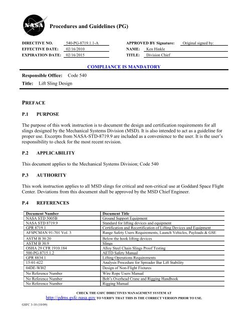
Procedures <strong>and</strong> Guidelines (<strong>PG</strong>)<br />
DIRECTIVE NO. <strong>540</strong>-<strong>PG</strong>-<strong>8719.1.1</strong>-A APPROVED BY Signature: Original signed by:<br />
EFFECTIVE DATE: 02/16/2010 NAME: Ken Hinkle<br />
EXPIRATION DATE: 02/16/2015 TITLE: Division Chief<br />
COMPLIANCE IS MANDATORY<br />
Responsible Office: Code <strong>540</strong><br />
Title: Lift Sling Design<br />
PREFACE<br />
P.1 PURPOSE<br />
The purpose of this work instruction is to document the design <strong>and</strong> certification requirements for all<br />
slings designed by the Mechanical Systems Division (MSD). It is also intended to act as a guideline for<br />
proper use. Excerpts from <strong>NASA</strong>-STD-8719.9 are included as a convenience to the user. It is the user’s<br />
responsibility to check for the most recent revision.<br />
P.2 APPLICABILITY<br />
This document applies to the Mechanical Systems Division; Code <strong>540</strong><br />
P.3 AUTHORITY<br />
This work instruction applies to all MSD slings for critical <strong>and</strong> non-critical use at Goddard Space Flight<br />
Center. Deviations from this document shall be approved by the MSD Chief Engineer.<br />
P.4 REFERENCES<br />
Document Number<br />
<strong>NASA</strong> STD 5005B<br />
<strong>NASA</strong> STD 8719.9<br />
GPR 8719.1<br />
AFSPCMAN 91-701 Vol. 3<br />
GSFC 3-18 (10/09)<br />
Document Title<br />
Ground Support Equipment<br />
St<strong>and</strong>ard for lifting devices <strong>and</strong> equipment<br />
Certification <strong>and</strong> Recertification of Lifting Devices <strong>and</strong> Equipment<br />
Range Safety Users Requirements, Launch Vehicles, Payloads & GSE<br />
ASTM B 30.20<br />
Below the hook lifting devices<br />
ASTM B 30.9<br />
Slings<br />
OSHA 29 CFR 1910.184<br />
Alloy Steel Chain Slings Proof Testing<br />
500-<strong>PG</strong>-8715.1.2<br />
AETD Safety Manual<br />
GPR 8834.1<br />
Lifting Operations Requirements<br />
15-01-422 Analysis Procedure for Spreader Bar Lift Stability<br />
04DE-WI02<br />
Design of Non-Flight Fixtures<br />
No Reference Number<br />
Wire Rope Users Manual<br />
No Reference Number<br />
Bob’s Overhead Crane <strong>and</strong> Rigging H<strong>and</strong>book<br />
No Reference Number<br />
Rigging Manual<br />
CHECK THE GSFC DIRECTIVES MANAGEMENT SYSTEM AT<br />
http://gdms.gsfc.nasa.gov TO VERIFY THAT THIS IS THE CORRECT VERSION PRIOR TO USE.
DIRECTIVE NO. <strong>540</strong>-<strong>PG</strong>-<strong>8719.1.1</strong>-A Page 2 of 37<br />
EFFECTIVE DATE: 02/16/2010<br />
EXPIRATION DATE: 02/16/2015<br />
P.5 CANCELLATION<br />
N/A<br />
P.6 SAFETY<br />
N/A<br />
P.7 TRAINING<br />
N/A<br />
P.8 RECORDS<br />
Record Title Record Custodian Retention<br />
Stress Analysis Sling Owner 5 Yrs or until Project Completion<br />
Stability Analysis Sling Owner 5 Yrs or until Project Completion<br />
Proof Test Sling Owner 5 Yrs or until Project Completion<br />
NDT Report Sling Owner 5 Yrs or until Project Completion<br />
* NRRS – <strong>NASA</strong> Records Retention Schedule (NPR 1441.1)<br />
P.9 METRICS<br />
N/A<br />
GSFC 3-18 (10/09)<br />
CHECK THE GSFC DIRECTIVES MANAGEMENT SYSTEM AT<br />
http://gdms.gsfc.nasa.gov TO VERIFY THAT THIS IS THE CORRECT VERSION PRIOR TO USE.
DIRECTIVE NO. <strong>540</strong>-<strong>PG</strong>-<strong>8719.1.1</strong>-A Page 3 of 37<br />
EFFECTIVE DATE: 02/16/2010<br />
EXPIRATION DATE: 02/16/2015<br />
PROCEDURES<br />
In this document, a requirement is identified by “shall,” a good practice by “should,” permission by<br />
“may” or “can,” expectation by “will,” <strong>and</strong> descriptive material by “is.”<br />
Design<br />
Strength Requirements:<br />
All hardware shall be designed with the minimum design factors listed in table 1. For slings that will<br />
be utilized at other sites (i.e. Kennedy Space Center, Marshall Space Center, etc.) the design<br />
requirements from these operational centers must be identified early in the sling design process<br />
Note:<br />
Table 1. Sling Design Load Factors, Factors of Safety <strong>and</strong> Proof Test Factors<br />
Design Load Factor Factor of Safety Proof Test Factors<br />
Item<br />
G’s<br />
Vertical Lateral Ultimate Yield Initial Periodic<br />
Alloy Steel Chain 1.0 0.0 5.0 2 1<br />
Wire Rope 1.0 0.0 5.0 2 1<br />
Metal Mesh 1.0 0.0 5.0 2 1<br />
Synthetic Rope 1.0 0.0 10.0 2 1<br />
Synthetic Web 1.0 0.0 5.0* 2 1<br />
Linear Fiber 1.0 0.0 5.0* 2 1<br />
Shackles, D-Rings,<br />
Turnbuckles, Eye 1.0 0.0 5.0 2 1<br />
Bolts, Hoist Rings<br />
Structural Slings 1.0 0.0 5.0 3.0 2 1<br />
S/C MGSE I/F** 1.6 0.25 1.4 1.25 1.25 N/A<br />
(*) If the sling is used at the Eastern or Western Range, the factor of safety shall be 10.0. Ref.<br />
AFSPCMAN 91-701 V3 (Range Safety Users Requirements, Launch Vehicles, Payloads & GSE)<br />
(**) This requirement applies to the spacecraft hardware at its lift-sling attachment points <strong>and</strong><br />
constitutes an additional spacecraft load case beyond those required for launch loads, test loads,<br />
operational loads, etc. The vertical <strong>and</strong> lateral design load factors are applied simultaneously.<br />
GSFC 3-18 (10/09)<br />
CHECK THE GSFC DIRECTIVES MANAGEMENT SYSTEM AT<br />
http://gdms.gsfc.nasa.gov TO VERIFY THAT THIS IS THE CORRECT VERSION PRIOR TO USE.
DIRECTIVE NO. <strong>540</strong>-<strong>PG</strong>-<strong>8719.1.1</strong>-A Page 4 of 37<br />
EFFECTIVE DATE: 02/16/2010<br />
EXPIRATION DATE: 02/16/2015<br />
Strength Analysis<br />
A stress analysis shall be prepared <strong>and</strong> documented for all lifting assemblies designed by MSD.<br />
Strength analysis of multiple leg lift assemblies shall assume a worst case load condition of two legs<br />
sharing the load. A waiver to this requirement will be considered if analysis shows that worst case<br />
loading conditions always will share the load between more than two legs. The loads reacted by each<br />
leg shall be calculated based on the actual center of gravity location for each lift configuration <strong>and</strong><br />
the worst case loads shall govern. The analysis shall calculate stress <strong>and</strong>/or load levels in all loaded<br />
components <strong>and</strong> tabulate margins of safety (MS) based on material allowable strengths or load<br />
capability. For a flight project, the strength analysis shall be approved by the by the Product Design<br />
Lead (PDL), otherwise Branch Head approval shall be required.<br />
MS=[Allowable Strength(or Load) /( F.S. x Actual Stress (or Load))] – 1<br />
Stability Analysis<br />
A stability analysis shall be prepared <strong>and</strong> documented for each lifting configuration.<br />
Each configuration shall meet the stability <strong>and</strong> flip over criteria defined in Appendix B. (Analysis<br />
Procedure for Spreader Bar Lift Stability). Appendix B includes the<br />
recommended stability <strong>and</strong> flip over analysis technique.<br />
The analysis starts with the categorization of the lift arrangement, continues with checking the<br />
stability <strong>and</strong> flipping criteria, <strong>and</strong> concludes with a look at the energy or force to cause tip over.<br />
Both elevation views for each lift shall be considered.<br />
It is important to insure the actual lift arrangement matches the stability analysis. For a flight project,<br />
the stability analysis shall be approved by the by the Product Design Lead (PDL), otherwise Branch<br />
Head approval shall be required.<br />
Lift Sling Components<br />
Any lifting equipment that contains an OEM warning of “not recommended for lifting” shall not be<br />
used.<br />
All Lift Equipment hardware components shall be traceable to a credible source of information, such<br />
as OSHA, OEM, etc., for certifiability.<br />
Turnbuckles:<br />
Turnbuckles that contain an OEM warning of “not recommended for lifting” shall not be used.<br />
All Turnbuckles shall be used in a straight line pull without any bending forces.<br />
GSFC 3-18 (10/09)<br />
CHECK THE GSFC DIRECTIVES MANAGEMENT SYSTEM AT<br />
http://gdms.gsfc.nasa.gov TO VERIFY THAT THIS IS THE CORRECT VERSION PRIOR TO USE.
DIRECTIVE NO. <strong>540</strong>-<strong>PG</strong>-<strong>8719.1.1</strong>-A Page 5 of 37<br />
EFFECTIVE DATE: 02/16/2010<br />
EXPIRATION DATE: 02/16/2015<br />
If jam nuts are present on turnbuckles, do not tighten them<br />
Turnbuckles are made for adjustment up to the tension produced by the Safe Working Load (SWL).<br />
They are not however, designed for repeated adjustment at high loads. Torqueing the threads at high<br />
load may cause binding due to the galvanizing flaking off. The preferred method of turnbuckle<br />
adjustment under load is to unload the turnbuckle sufficient to minimize any potential galling.<br />
Removal of at least 75% of the load is recommended for repeated adjustment under load.<br />
If at all practical turnbuckles should be avoided in the design of critical lift slings.<br />
Wire rope assemblies<br />
Flemish eyes are the preferred termination method of wire rope assemblies. Other acceptable types<br />
of wire rope terminations are wire rope socket <strong>and</strong> wire rope socket swaged.( refer to Wire Rope<br />
Users Manual, American Iron <strong>and</strong> Steel Institute, 1979, Pages 26-27. <strong>and</strong> Bob’s Overhead Crane <strong>and</strong><br />
Rigging H<strong>and</strong>book, Second Edition, Page 112.)<br />
Flemish Eye Splice<br />
In the st<strong>and</strong>ard flemish eye mechanical splice, rope is separated into two parts - 3 adjacent str<strong>and</strong>s,<br />
<strong>and</strong> 3 adjacent str<strong>and</strong>s <strong>and</strong> core. These two parts are then re-laid back in opposite directions to form<br />
an eye, <strong>and</strong> ends are secured with a pressed metal sleeve.<br />
Flemish Eye Splice<br />
GSFC 3-18 (10/09)<br />
CHECK THE GSFC DIRECTIVES MANAGEMENT SYSTEM AT<br />
http://gdms.gsfc.nasa.gov TO VERIFY THAT THIS IS THE CORRECT VERSION PRIOR TO USE.
DIRECTIVE NO. <strong>540</strong>-<strong>PG</strong>-<strong>8719.1.1</strong>-A Page 6 of 37<br />
EFFECTIVE DATE: 02/16/2010<br />
EXPIRATION DATE: 02/16/2015<br />
Mechanical spliced ends are not permitted.<br />
Mechanical clips are not permitted in wire rope end fittings. (refer to Rigging Manual, D.E. Dickie,<br />
1975, Page 46-47.)<br />
Eye bolts<br />
Eye bolts shall not be used in applications that impart bending loads into the eye bolt.<br />
Eye bolts shall only be used in purely axial (along the center line of the eye bolt) loading conditions.<br />
Swivel hoist rings <strong>and</strong> safety hoist rings shall be used in all non-axial loading applications.<br />
Materials not Permitted<br />
Natural rope <strong>and</strong> wire rope clips shall not be used in slings or rigging hardware to hoist personnel or<br />
loads. The fold back metal pressed sleeve or clip technique also shall not be used in slings or rigging<br />
hardware (refer to <strong>NASA</strong> Std 8719.9 section 10.7.g).<br />
Due to cleanliness concerns <strong>and</strong> brittle characteristics at low temperatures, sling components made<br />
from plain carbon steel materials shall not be used if the sling will be utilized inside a thermal<br />
vacuum chamber during test (refer to 04DE-WI02 “Design of Non-Flight Fixtures” section 6.2.1).<br />
H. Single Point Failure Weld<br />
All critical welds shall have a surface NDT (magnetic particle or dye penetrant) performed after the<br />
initial proof test <strong>and</strong> after the periodic proof test. The following table 2.clarifies the inspection<br />
methods for critical welds in structural slings.<br />
GSFC 3-18 (10/09)<br />
CHECK THE GSFC DIRECTIVES MANAGEMENT SYSTEM AT<br />
http://gdms.gsfc.nasa.gov TO VERIFY THAT THIS IS THE CORRECT VERSION PRIOR TO USE.
DIRECTIVE NO. <strong>540</strong>-<strong>PG</strong>-<strong>8719.1.1</strong>-A Page 7 of 37<br />
EFFECTIVE DATE: 02/16/2010<br />
EXPIRATION DATE: 02/16/2015<br />
TABLE 2<br />
Nondestructive Testing <strong>and</strong> Load Testing Requirements for Lifting Equipment Certification <strong>and</strong> Recertification<br />
EQUIPMENT POST-PROOF NDT2 POST-PERIODIC NDT2<br />
Alloy Steel Chain Slings Visual Visual<br />
Wire Rope Slings Visual Visual<br />
Metal Mesh Slings Visual Visual<br />
Synthetic Rope Slings Visual Visual<br />
Synthetic Web Slings Visual Visual<br />
Linear Fiber Slings Visual Visual<br />
Critical Welds: Surface<br />
Critical Welds: Surface<br />
Structural Slings<br />
Noncritical Welds: Visual<br />
Noncritical Welds: Visual<br />
Shackles, D-rings, Turnbuckles,<br />
Lifting Lugs, Safety Hoist<br />
Rings. Etc.<br />
Single <strong>and</strong> Non-Single Failure<br />
Load Path: Surface<br />
Single <strong>and</strong> Non-Single Failure<br />
Load Path: Surface<br />
Lifting lugs, including eyebolts. which are permanently affixed to the load are considered to<br />
be part of the load <strong>and</strong> are exempt from load testing <strong>and</strong> NDT, but must be qualified by<br />
calculation by the owning organization.<br />
POST-PROOF = After the initial, first-time proof load test of new or extensively modified<br />
items.<br />
POST-PERIODIC = After the annual rated load test of the item.<br />
With the exception of thimbles <strong>and</strong> tapered end fittings, metallic fittings that are<br />
integral to slings are included. Thimbles <strong>and</strong> tapered end fitting are subject to visual NDT<br />
only.<br />
GSFC 3-18 (10/09)<br />
CHECK THE GSFC DIRECTIVES MANAGEMENT SYSTEM AT<br />
http://gdms.gsfc.nasa.gov TO VERIFY THAT THIS IS THE CORRECT VERSION PRIOR TO USE.
DIRECTIVE NO. <strong>540</strong>-<strong>PG</strong>-<strong>8719.1.1</strong>-A Page 8 of 37<br />
EFFECTIVE DATE: 02/16/2010<br />
EXPIRATION DATE: 02/16/2015<br />
Best Practices<br />
The following guidelines for the selection of materials, components <strong>and</strong> use of design rules for<br />
lifting assemblies are recommended.<br />
a. Thin plate structural slings with little out of plane inertia should be avoided due to<br />
buckling susceptibility.<br />
b. Align structural sling load line to avoid local induced moments. Lines of action should<br />
intersect at the neutral axes of the sling members.<br />
c. All bolted joints should be designed fail-safe where the highest loaded fastener in the<br />
pattern can be removed <strong>and</strong> the remaining fasteners can carry the load with a 1.0 factor of<br />
safety. If the joint is not fail-safe, then some method will be needed to ensure that if the<br />
fasteners are removed following the proof test, the bolts are indexed to the appropriate<br />
joints.<br />
d. Bird Cage lifts- The Bird Cage lift configuration is the least stable due to its kinematics.<br />
Efforts should be made to change the lift points to obtain a parallel type lift. Refer to Page<br />
3 of Appendix B for Bird Cage Lift description.<br />
e. Umbrella Lifts- The Umbrella lifts are the most stable due to their kinematics. Refer to<br />
page 4 of Appendix B for Umbrella Lift description.<br />
f. During the process of a lift, the risks to equipment <strong>and</strong> personnel increases as the lift is<br />
raised or as the speed increases. For this reason, should large traversals of the bridge<br />
crane or trolley be required, the load should be kept as close to the floor as practical,<br />
taking into account possible swinging due to crane jogs.<br />
g. When practical, design in castors for transporting heavy lifting frames <strong>and</strong> spreader bars.<br />
h. To prevent the inadvertent contamination of sensitive flight hardware by an overhead oil<br />
leak, consider incorporating a drip guard or dust cover into the sling design.<br />
i. If the sling will be utilized inside a thermal vacuum chamber during test, box beams<br />
should be avoided. It is difficult to properly clean the inside surfaces of box beams <strong>and</strong><br />
box beam weldments can result in virtual leaks if not properly vented.<br />
j. When designing a lift sling using a spreader bar it is preferred to use upper wire rope<br />
assemblies that connect the spreader bar to the crane rather than just connecting the crane<br />
directly to the spreader bar. This increases the dimension "b" called out in the stability<br />
criteria in appendix B, thereby increasing the stability of the lift. In other words avoid<br />
using a strongback.<br />
Proof Testing<br />
When slings are composed of major components that fall into more than one of the categories listed<br />
in table 1., the components shall be tested individually according to applicable requirements <strong>and</strong> then<br />
as a system to the lowest proof test factor.<br />
All lifting equipment shall be proof tested <strong>and</strong> certified prior to use in accordance with Table 1:<br />
GSFC 3-18 (10/09)<br />
CHECK THE GSFC DIRECTIVES MANAGEMENT SYSTEM AT<br />
http://gdms.gsfc.nasa.gov TO VERIFY THAT THIS IS THE CORRECT VERSION PRIOR TO USE.
DIRECTIVE NO. <strong>540</strong>-<strong>PG</strong>-<strong>8719.1.1</strong>-A Page 9 of 37<br />
EFFECTIVE DATE: 02/16/2010<br />
EXPIRATION DATE: 02/16/2015<br />
K. Periodic Load Testing<br />
Slings shall undergo periodic load tests at least every 4 years in accordance with Table 1. Slings<br />
used for critical lifts shall be load tested at least once per year in accordance with Table 1.<br />
L. Certification <strong>and</strong> Tagging of Slings<br />
Certification/ re-certification tags are required as described in <strong>NASA</strong>-STD-8719.9 section 10.3.5. A<br />
system has been developed to identify slings used in critical lift applications. Completely assembled<br />
slings that are critical lift certified are marked conspicuously so that the operator <strong>and</strong> quality<br />
assurance personnel can identify them as such.<br />
Disassembly of the sling shall void the proof test certification unless items/components are identified<br />
such that reassembly is identical to the original proof test configuration.<br />
Only the Recertification Program Manager’s Office (or his designee) can certify, <strong>and</strong> tag lift slings<br />
for use at GSFC.<br />
Pre-Use Sling Inspection<br />
Daily Inspections- These inspections shall be performed by the user prior to first use each day the<br />
sling is to be used <strong>and</strong> shall include the following:<br />
a) Check for defects such as cracks, deformations, gouges, galling, kinks, crushed areas <strong>and</strong><br />
corrosion.<br />
b) Check for proper configuration (the lifting assembly <strong>and</strong> associated hardware, as proof load<br />
tested).<br />
Periodic Inspections- The following inspections shall be performed at least once a year:<br />
Alloy Steel Chain Slings- Visually inspect in accordance with <strong>NASA</strong>-STD-8719.9 section 10.4.5.a<br />
(refer to Appendix A)<br />
Wire Rope Slings- Visually inspect in accordance with <strong>NASA</strong>-STD-8719.9 section 10.4.5.b ( refer to<br />
Appendix A)<br />
Metal Mesh Slings- Visually inspect in accordance with <strong>NASA</strong>-STD-8719.9 section 10.4.5.c (refer<br />
to Appendix A)<br />
Synthetic Rope Slings- Visually inspect in accordance with <strong>NASA</strong>-STD-8719.9 section 10.4.5.d<br />
(refer to Appendix A)<br />
GSFC 3-18 (10/09)<br />
CHECK THE GSFC DIRECTIVES MANAGEMENT SYSTEM AT<br />
http://gdms.gsfc.nasa.gov TO VERIFY THAT THIS IS THE CORRECT VERSION PRIOR TO USE.
DIRECTIVE NO. <strong>540</strong>-<strong>PG</strong>-<strong>8719.1.1</strong>-A Page 10 of 37<br />
EFFECTIVE DATE: 02/16/2010<br />
EXPIRATION DATE: 02/16/2015<br />
Synthetic Web <strong>and</strong> Linear Fiber Slings- Visually inspect in accordance with <strong>NASA</strong>-STD-8719.9<br />
section 10.4.5.e (refer to Appendix A)<br />
Structural Slings- Visually inspect <strong>and</strong> NDT in accordance with <strong>NASA</strong>-STD-8719.9 section 10.4.5.f<br />
(refer to Appendix A)<br />
Rejected Slings- All slings rejected during inspection shall be removed from service.<br />
Personnel Certification<br />
Only certified (licensed) crane operators/riggers are authorized to perform rigging tasks for lifting<br />
assemblies, equipment <strong>and</strong>/or operations. Crane operators/riggers shall be certified by RECERT in<br />
accordance with <strong>NASA</strong>-STD-8719.9 <strong>and</strong> GPR 8719.1 requirements.<br />
Personnel performing NDT shall be qualified <strong>and</strong> certified in accordance with section 1.9 of <strong>NASA</strong>-<br />
STD-8719.9.<br />
GSFC 3-18 (10/09)<br />
CHECK THE GSFC DIRECTIVES MANAGEMENT SYSTEM AT<br />
http://gdms.gsfc.nasa.gov TO VERIFY THAT THIS IS THE CORRECT VERSION PRIOR TO USE.
DIRECTIVE NO. <strong>540</strong>-<strong>PG</strong>-<strong>8719.1.1</strong>-A Page 11 of 37<br />
EFFECTIVE DATE: 02/16/2010<br />
EXPIRATION DATE: 02/16/2015<br />
Excerpts from<br />
STANDARD FOR<br />
LIFTING DEVICES AND EQUIPMENT<br />
<strong>NASA</strong>-STD-8719.9<br />
(These excerpts are listed for convenience. Be sure to check for the latest revision)<br />
1.9 Personnel Performing Nondestructive Testing. Personnel performing lifting devices <strong>and</strong> equipment<br />
nondestructive testing (NDT), including visual inspections, shall be qualified <strong>and</strong> certified in accordance with<br />
written practices meeting the requirements contained in American Society for Nondestructive Testing (ASNT)<br />
Recommended Practice No. SNT-TC-1A, Personnel Qualification <strong>and</strong> Certification in Nondestructive Testing.<br />
10.3 Testing. The following proof load <strong>and</strong> periodic load tests apply to slings except as noted in paragraph<br />
10.3.3. Turnbuckles shall be tested at the open position as a minimum. It is recommended that turnbuckles be<br />
tested at the open, closed, <strong>and</strong> midway positions. These tests shall be performed by qualified personnel according<br />
to written (specific or general) technical operating procedures. The acceptable tolerance for load test accuracy is<br />
+5/-0 percent. When slings are composed of major components that fall into more than one of the categories<br />
listed in Table 10-2, the components shall be tested individually according to applicable requirements <strong>and</strong> then as<br />
a system to the lowest test value (if practical). An inspection shall be performed after each load test <strong>and</strong> prior to<br />
release for service to ensure there is no damage. A periodic load test requirement can be fulfilled by a concurrent<br />
proof load test. The load shall be held for a minimum of 3 minutes for load tests.<br />
10.3.1 Proof Load Test. Before first use, all new, extensively modified, repaired, or altered slings shall undergo a<br />
proof load test at a specified factor of the rated load according to Table 10-2. Proof load tests performed by the<br />
manufacturer prior to delivery are acceptable, if the necessary load test papers are provided to verify the extent<br />
<strong>and</strong> thoroughness of the test on the specific item. A proof load test also may be performed at a prescribed time<br />
when there is a question in design or previous testing. All components shall be tested together as a system, if<br />
practical. Prior to first use, all lifting interfaces such as eyebolts, D-rings, <strong>and</strong> lifting lugs permanently attached to<br />
the load shall be proof load tested if feasible. For lifting interfaces, when deemed unfeasible by the responsible<br />
design organization <strong>and</strong> accepted by the user organization, based on possible overloading of structural members<br />
not required during lifting or other considerations, this proof load test can be eliminated. However, design<br />
analysis <strong>and</strong> inspection shall be used to verify the integrity of the interface.<br />
GSFC 3-18 (10/09)<br />
CHECK THE GSFC DIRECTIVES MANAGEMENT SYSTEM AT<br />
http://gdms.gsfc.nasa.gov TO VERIFY THAT THIS IS THE CORRECT VERSION PRIOR TO USE.
DIRECTIVE NO. <strong>540</strong>-<strong>PG</strong>-<strong>8719.1.1</strong>-A Page 12 of 37<br />
EFFECTIVE DATE: 02/16/2010<br />
EXPIRATION DATE: 02/16/2015<br />
10.3.2 Periodic Load Test. Slings shall undergo periodic load tests at least every 4 years at a specific load test<br />
factor of the design rated load as given in Table 10-3. All components shall be tested together as a system, if<br />
practical. Slings used for critical lifts shall be load tested at least once per year. Slings used infrequently for<br />
critical lifts shall be load tested before each critical lift if it has been over a year since the last load test. Lifting<br />
interfaces such as eyebolts, D-rings, <strong>and</strong> lifting lugs permanently attached to the load are exempt from periodic<br />
load testing.<br />
10.3.3 Non-Load Test Slings. Due to unique design <strong>and</strong> usage requirements, a sling may be designated as a nonload<br />
test sling by the LDEM, with concurrence from the affected/responsible program/project office, the<br />
responsible safety, design engineering, systems engineering, operations, <strong>and</strong> maintenance organizations. Such<br />
slings do not require periodic load tests. Inspections shall be conducted in accordance with paragraph 10.4. This<br />
non-load test designation shall be formally documented by each installation <strong>and</strong> the sling marked accordingly to<br />
designate it as a non-load test sling<br />
10.3.4 Sling Rated Load. Rated loads for slings shall be based on the periodic load test weight divided by the<br />
periodic load test factor (see Table 10-3). For metal mesh slings, the rated capacity will be noted for vertical<br />
basket <strong>and</strong> choker hitch configurations. For synthetic rope slings, used in noncritical lifts, a 50-percent derating<br />
for use is recommended. For synthetic rope slings used in critical lifts, a 50-percent derating is required.<br />
GSFC 3-18 (10/09)<br />
CHECK THE GSFC DIRECTIVES MANAGEMENT SYSTEM AT<br />
http://gdms.gsfc.nasa.gov TO VERIFY THAT THIS IS THE CORRECT VERSION PRIOR TO USE.
DIRECTIVE NO. <strong>540</strong>-<strong>PG</strong>-<strong>8719.1.1</strong>-A Page 13 of 37<br />
EFFECTIVE DATE: 02/16/2010<br />
EXPIRATION DATE: 02/16/2015<br />
10.3.5 Test Reports <strong>and</strong> Periodic Recertification Tags.<br />
a. Written, dated, <strong>and</strong> signed reports shall be prepared after each test. Inadequacies shall be documented <strong>and</strong>, if<br />
determined to be a hazard, corrected prior to further use. These reports shall be kept on file by the owner<br />
organization for a minimum of two test cycles <strong>and</strong> shall be made readily available.<br />
b. Following the load test, all slings shall be given a permanently affixed tag identifying the equipment (part<br />
number) <strong>and</strong> stating the rated capacity based on the load test value <strong>and</strong> the next periodic load test due date or load<br />
test expiration date. For alloy steel chains, size, grade, <strong>and</strong> reach shall be stated along with the rated load. For<br />
synthetic rope slings used for critical lifts, the marked rated load shall be 50 percent of the manufacturer’s rated<br />
load. The type of material shall also be stated. All load bearing components shall be traceable to the most recent<br />
load test. This may be accomplished by clearly marking/coding or tethering all components of the assembly,<br />
through configuration control, or other procedures. (NOTE: Load bearing components not traceable to load test<br />
will invalidate the load test of the whole assembly.)<br />
10.4 Inspection.<br />
810.4.1 Inspections, as described below, shall be performed on all slings. Inspections shall be performed<br />
according to this section, the manufacturers’ recommendations, <strong>and</strong> ASME B30.9. Visual inspections for cracks,<br />
deformations, gouges, galling, kinks, crushed areas, corrosion, <strong>and</strong> proper configuration shall be performed each<br />
day the sling is used, prior to first use. An indepth inspection shall be performed annually or when a sling is<br />
suspected to have even a small loss of strength or is repaired. Inspections shall be performed by qualified<br />
personnel according to approved technical operating procedures. Inadequacies shall be documented <strong>and</strong>, if<br />
determined to be a safety hazard, tagged out <strong>and</strong> corrected prior to further use.<br />
10.4.2 All new, extensively repaired, or modified slings shall be given a daily <strong>and</strong> a periodic inspection prior to<br />
first use. For component repair on slings, only the inspections that apply to the repaired portion need to be<br />
performed prior to first use unless a periodic inspection interval expires during the downtime (see paragraph<br />
10.4.5).<br />
10.4.3 Slings in regular service (used at least once a month) shall be inspected as required in paragraphs 10.4.4<br />
<strong>and</strong> 10.4.5. Idle <strong>and</strong> st<strong>and</strong>by slings shall be inspected according to paragraph 10.4.6.<br />
10.4.4 Daily Inspections. These inspections shall be performed prior to first use each<br />
day the sling is used <strong>and</strong> shall include the following:<br />
a. Check for defects such as cracks, deformations, gouges, galling, kinks, crushed areas, <strong>and</strong> corrosion.<br />
b. Check for proper configuration (the lifting assembly <strong>and</strong> associated hardware, as proof load tested).<br />
10.4.5 Periodic Inspections. The following inspections shall be performed at least once a year, unless otherwise<br />
specified below. The need to replace or repair slings shall be determined by a certified or otherwise qualified<br />
person based on an evaluation of inspection results. Any discrepancy (deterioration or damage) is sufficient<br />
reason for questioning continued use of the sling (see Wire Rope Users Manual for additional information on<br />
wire rope inspections):<br />
a. Alloy Steel Chain<br />
(1) Inspect each link individually to ensure every link hangs freely with adjoining link.<br />
(2) Ensure that wear, corrosion, or deformities at any point on chain do not exceed 20 percent of original<br />
dimensions.<br />
(3) Ensure that master links are not deformed.<br />
GSFC 3-18 (10/09)<br />
CHECK THE GSFC DIRECTIVES MANAGEMENT SYSTEM AT<br />
http://gdms.gsfc.nasa.gov TO VERIFY THAT THIS IS THE CORRECT VERSION PRIOR TO USE.
DIRECTIVE NO. <strong>540</strong>-<strong>PG</strong>-<strong>8719.1.1</strong>-A Page 14 of 37<br />
EFFECTIVE DATE: 02/16/2010<br />
EXPIRATION DATE: 02/16/2015<br />
b. Wire Rope Slings<br />
(1) Ensure that there are fewer than 10 r<strong>and</strong>omly distributed broken wires in one rope lay or 5 broken wires in 1<br />
str<strong>and</strong> in 1 lay.<br />
(2) Ensure wear or scraping is less than 1/3 the original diameter of outside individual wires.<br />
(3) Inspect for kinking, crushing, bird caging, or any other distortion of the rope structure.<br />
(4) Inspect for excessive heat damage.<br />
(5) Inspect for cracked, deformed, or worn end attachments.<br />
(6) Inspect for significantly corroded rope or end attachments.<br />
c. Metal Mesh Slings<br />
(1) Ensure that there are no broken welds or brazed joints along the sling edge.<br />
(2) Ensure that reduction in wire diameter does not exceed 25 percent due to abrasion or 15 percent due to<br />
corrosion.<br />
(3) Inspect for lack of flexibility due to distortion of the fabric.<br />
(4) Ensure that there is no more than a 25 percent reduction of the original cross-sectional area of metal at any<br />
point around h<strong>and</strong>le eyes.<br />
(5) Inspect for distortion of either h<strong>and</strong>le out of plane, more than 10-percent decrease in eye width, <strong>and</strong> more than<br />
10-percent increase in the receiving h<strong>and</strong>le slot depth.<br />
d. Synthetic Rope Slings<br />
(1) Inspect for abnormal wear.<br />
(2) Ensure that there is no powdered fiber between st<strong>and</strong>s.<br />
(3) Inspect for broken or cut fibers.<br />
(4) Ensure that there is no rotting or acid or caustic burns.<br />
(5) Inspect for distortion of associated hardware.<br />
e. Synthetic Web <strong>and</strong> Linear Fiber Slings<br />
(1) Ensure that there are no acid or caustic burns.<br />
(2) Inspect for melting or charring of any part of surface.<br />
(3) Inspect for snags, punctures, tears, <strong>and</strong> cuts.<br />
(4) Inspect for broken or worn stitches <strong>and</strong> rotting.<br />
(5) Ensure that wear or elongation does not exceed amount recommended by the manufacturer.<br />
(6) Perform all inspections provided for by the sling manufacturer. This may include red fibers used as a wear<br />
indicator, or a fiber optic sling damage indicator, or some other NDT method designed into the sling.<br />
GSFC 3-18 (10/09)<br />
CHECK THE GSFC DIRECTIVES MANAGEMENT SYSTEM AT<br />
http://gdms.gsfc.nasa.gov TO VERIFY THAT THIS IS THE CORRECT VERSION PRIOR TO USE.
DIRECTIVE NO. <strong>540</strong>-<strong>PG</strong>-<strong>8719.1.1</strong>-A Page 15 of 37<br />
EFFECTIVE DATE: 02/16/2010<br />
EXPIRATION DATE: 02/16/2015<br />
f. Structural Slings<br />
(1) Verify overall that there is no evidence of damage, gouges in metal, loose bolts, rivets, connections, or<br />
deformations such as galling or gouges in pins, eyes, <strong>and</strong> end connections.<br />
(2) Ensure that there are no bent, deformed, cracked, or excessively corroded support or main members.<br />
(3) Without disassembly, inspect load bearing bolts for evidence of deterioration. Verify that assemblies are<br />
intact <strong>and</strong> that there has been no shifting or relative motion of parts.<br />
(4) Inspect attachment <strong>and</strong> lifting lugs for visual deformation <strong>and</strong> evidence of local yielding.<br />
(5) Ensure that there are no elongated attachment or lifting holes.<br />
(6) Inspect around fasteners for local yielding <strong>and</strong> deformation.<br />
(7) Remove <strong>and</strong> inspect load bearing slip pins for deformation, evidence of bending, abnormal defects such as<br />
galling, scoring, brinelling, <strong>and</strong> diameters not within design tolerances. Verify that there are no cracks by<br />
performing a surface NDT.<br />
(8) Inspect pin bores for deformation, local yielding, scoring, galling, brinelling, <strong>and</strong> diameters not within design<br />
tolerances. Verify that there are no cracks by performing a surface NDT.<br />
(9) Inspect welds for cracks, evidence of deformation, deterioration, damage, or other defects by:<br />
(a) Visual inspection of all welds.<br />
(b) Ultrasonics, radiography, magnetic particle, liquid penetrant, or eddy current as appropriate for critical welds<br />
as identified on the design drawings. Inspect a minimum of 1/2 inch on each side of the weld to ensure the heat<br />
affected zone is included. Verify that there are no cracks.<br />
(10) Inspect all parts, particularly bare metal, for corrosion. Corrosion-protect all surfaces that are not to be<br />
painted, lubricated, or coated with strippable vinyl. Do not paint over uninspected areas, or cracks, deformations,<br />
deterioration, or other damage until engineering assessment has been made.<br />
(11) Inspect hooks for deformations or cracks (see Section 7).<br />
g. Rejected Slings. All slings rejected during inspection shall be marked. An engineering assessment will be<br />
made to determine if the sling is repairable. Non-repairable slings will be destroyed as soon as possible to avoid<br />
unintentional use.<br />
10.4.6 Idle <strong>and</strong> St<strong>and</strong>by Slings. Idle <strong>and</strong> st<strong>and</strong>by slings shall be inspected prior to first use according to the<br />
requirements in paragraphs 10.4.4 <strong>and</strong> 10.4.5 unless these daily <strong>and</strong> periodic inspections were performed at<br />
required intervals during the idle/st<strong>and</strong>by period.<br />
10.4.7 Inspection Reports. Written, dated, <strong>and</strong> signed inspection reports shall be prepared after each periodic<br />
inspection. Inadequacies shall be documented <strong>and</strong>, if determined to be a hazard, corrected prior to further use.<br />
These reports shall be filed <strong>and</strong> made readily available by the organizational element responsible for inspecting<br />
sling(s).<br />
10.5 Maintenance. A maintenance program based on manufacturers’ recommendations, integrating proactive,<br />
reactive, preventive, <strong>and</strong> predictive maintenance shall be established to increase the probability the sling will<br />
function in the required manner over its design life cycle with a minimum of maintenance. The program shall<br />
include procedures <strong>and</strong> a scheduling system for normal periodic maintenance items, adjustments, replacements,<br />
<strong>and</strong> repairs. The program shall also ensure that records are kept <strong>and</strong> unsafe test <strong>and</strong> inspection discrepancies are<br />
documented <strong>and</strong> corrected. Any sling found in an unsafe operating condition shall be tagged out <strong>and</strong> removed<br />
from service until repaired. All repairs shall be made by qualified personnel in accordance with the<br />
manufacturers’ instructions. The need to repair or replace slings shall be determined by a certified or otherwise<br />
qualified person based on an evaluation of inspection results.<br />
GSFC 3-18 (10/09)<br />
CHECK THE GSFC DIRECTIVES MANAGEMENT SYSTEM AT<br />
http://gdms.gsfc.nasa.gov TO VERIFY THAT THIS IS THE CORRECT VERSION PRIOR TO USE.
DIRECTIVE NO. <strong>540</strong>-<strong>PG</strong>-<strong>8719.1.1</strong>-A Page 16 of 37<br />
EFFECTIVE DATE: 02/16/2010<br />
EXPIRATION DATE: 02/16/2015<br />
10.6 Personnel Certification.<br />
10.6.1 Program. Only certified (licensed) <strong>and</strong> trained riggers are authorized to perform rigging tasks for lifting<br />
devices, equipment, <strong>and</strong>/or operations. A comprehensive training, examination, <strong>and</strong> licensing program shall be<br />
established or made available. For those <strong>NASA</strong> installations/initiatives or sponsored programs <strong>and</strong> activities that<br />
do not have a training program, these requirements may be provided by a third party that is proficient in the<br />
principles of rigging. The rigging certification program will be reviewed at least annually to assure that the<br />
contents, training material, testing, <strong>and</strong> examination elements are up-to-date with current methods <strong>and</strong><br />
techniques; <strong>and</strong> that any “lessons-learned” are adequately addressed. Personnel performing NDT shall be<br />
qualified <strong>and</strong> certified in accordance with paragraph 1.9. Training shall be provided to observers <strong>and</strong> flagmen.<br />
All participants in the lifting operation shall have clearly defined roles <strong>and</strong> responsibilities.<br />
10.6.2 The certification program for rigging operations shall include the following <strong>and</strong> may be included in the<br />
operator training for the individual lifting device training <strong>and</strong> certification . If the general rigging is included in<br />
the specific lifting device certification <strong>and</strong> training program, sufficient rigging details shall be included in the<br />
training, testing <strong>and</strong> “h<strong>and</strong>s-on” examination portion of that lifting device training program to assure that each<br />
individual underst<strong>and</strong>s <strong>and</strong> demonstrates proficiency in the required rigging techniques <strong>and</strong> methods.<br />
The following shall be addressed in the qualification of individuals for “rigging certification.”<br />
a. Training<br />
(1) Classroom training in rigging safety, techniques, <strong>and</strong> methods, pre-use inspection, slings, <strong>and</strong><br />
attachment devices (for initial certification <strong>and</strong> as needed).<br />
(2) H<strong>and</strong>s-on training (for initial certification <strong>and</strong> as needed).<br />
(3) An annual review by supervision or other designated personnel of each individual’s performance as a<br />
rigger or operator/rigger to assure adequate proficiency in performing the necessary rigging tasks in a<br />
manner consistent with the principals, methods, <strong>and</strong> techniques associated with safe rigging practices.<br />
b. Examination<br />
(1) Physical examination (criteria to be determined by the cognizant medical official based upon the related<br />
requirements associated with performing rigging tasks).<br />
(2) Written examination.<br />
(3) Operational (practical) demonstration test (for initial certification only or to address new techniques or<br />
methods as required). Each individual shall demonstrate the ability to adequate determine <strong>and</strong>/or apply load<br />
weight, center of gravity <strong>and</strong> apply special articulating devices essential to the safe <strong>and</strong> successful lift operation.<br />
Riggers must demonstrate the ability to apply proper rigging principals, methods, <strong>and</strong> techniques using simulated<br />
loads of various weights, sizes, <strong>and</strong> configurations.<br />
c. Rigger Licensing/Certification<br />
An organization element shall be designated to issue rigger licenses/certifications. Provisions shall be made to<br />
suspend/revoke licenses or certifications for violation of safety requirements, failure to meet medical<br />
requirements, or acts of negligence in rigging. A program element to assure current rigger certification status of<br />
persons performing rigging tasks shall be established <strong>and</strong> implemented. The method of licensing is the<br />
responsibility of the organization element that is designated to issue the rigger licenses/certifications. Generally<br />
this will involve the use of “License/Certification Cards” issued to each individual or maintaining a master list of<br />
licensed/certified riggers that is readily available to assurance <strong>and</strong> supervisory personnel.<br />
GSFC 3-18 (10/09)<br />
CHECK THE GSFC DIRECTIVES MANAGEMENT SYSTEM AT<br />
http://gdms.gsfc.nasa.gov TO VERIFY THAT THIS IS THE CORRECT VERSION PRIOR TO USE.
DIRECTIVE NO. <strong>540</strong>-<strong>PG</strong>-<strong>8719.1.1</strong>-A Page 17 of 37<br />
EFFECTIVE DATE: 02/16/2010<br />
EXPIRATION DATE: 02/16/2015<br />
(2) Renewal of all rigger licenses/certifications shall require demonstration of proficiency or approval of<br />
supervision that proficiency is adequate <strong>and</strong> current. Licenses/certifications will expire at least every 4<br />
years. Renewal procedures <strong>and</strong> requirements will be established by the organizational element<br />
responsible for issuing rigger licenses/certifications <strong>and</strong> will include those requirements established in<br />
paragraphs 10.6.2 a. <strong>and</strong> 10.6.2 b.<br />
GSFC 3-18 (10/09)<br />
CHECK THE GSFC DIRECTIVES MANAGEMENT SYSTEM AT<br />
http://gdms.gsfc.nasa.gov TO VERIFY THAT THIS IS THE CORRECT VERSION PRIOR TO USE.
DIRECTIVE NO. <strong>540</strong>-<strong>PG</strong>-<strong>8719.1.1</strong>-A Page 18 of 37<br />
EFFECTIVE DATE: 02/16/2010<br />
EXPIRATION DATE: 02/16/2015<br />
GSFC 3-18 (10/09)<br />
CHECK THE GSFC DIRECTIVES MANAGEMENT SYSTEM AT<br />
http://gdms.gsfc.nasa.gov TO VERIFY THAT THIS IS THE CORRECT VERSION PRIOR TO USE.
DIRECTIVE NO. <strong>540</strong>-<strong>PG</strong>-<strong>8719.1.1</strong>-A Page 19 of 37<br />
EFFECTIVE DATE: 02/16/2010<br />
EXPIRATION DATE: 02/16/2015<br />
Background<br />
This specification is intended to aid the analyst in determining whether a spreader bar lift is stable. In<br />
general if the lowest lift attachment point is above the payload's center of gravity then the lift is deemed<br />
stable. If the lowest lift attach point is below the center of gravity, then further analysis is required. This<br />
procedure is intended to exp<strong>and</strong> on the JPL spreader bar lift stability specification found in appendix G<br />
of JPL Document #D6904 Dated February 1990. Additional analysis methods are offered. A further<br />
analysis shows that we must limit the lifts from being very tall <strong>and</strong> thin, even though they meet the JPL<br />
specification. Alternative methods to obtaining stability for these types of lifts are discussed. Tag Line<br />
usage, placement, <strong>and</strong> operational considerations with respect to lift height are also covered.<br />
Classification of Spreader Bar Lifts<br />
Spreader bar lifts fall into two major categories. The first is those in which the load center of gravity is<br />
below the lowest lift attach point of the lift arrangement. These lifts are inherently stable. For any angle<br />
of the spreader bar, the load raises. The other category, which is the subject of this procedure, are lifts in<br />
which the load center of gravity is above the lowest attach points of the lift arrangement. These lifts must<br />
be analyzed to determine if they will be stable under all conditions. In some configurations of these lifts,<br />
they may be marginally stable, however, experience shows that one must ensure stability under all lift<br />
conditions to prevent injury or damage. It is the intention of this specification to aid in the development<br />
of the analysis for these latter type lifts.<br />
Once a lift is determined to be of the type that the load center of gravity is above the lowest lift point of<br />
the lift arrangement, we must further determine if it is a parallel lift. Each of the main two sub-categories<br />
of lifts, symmetric <strong>and</strong> asymmetric, can have parallel lifts. Both symmetric <strong>and</strong> asymmetric lifts further<br />
have three sub-categories, parallel, bird-cage, <strong>and</strong>, umbrella lifts. Asymmetric lifts are those in which the<br />
center of gravity of the load does not fall along a perpendicular bisector of the upper spreader bar. The<br />
lifts typically have different length slings or wires from the spreader bar up to the hook lift point<br />
GSFC 3-18 (10/09)<br />
CHECK THE GSFC DIRECTIVES MANAGEMENT SYSTEM AT<br />
http://gdms.gsfc.nasa.gov TO VERIFY THAT THIS IS THE CORRECT VERSION PRIOR TO USE.
DIRECTIVE NO. <strong>540</strong>-<strong>PG</strong>-<strong>8719.1.1</strong>-A Page 20 of 37<br />
EFFECTIVE DATE: 02/16/2010<br />
EXPIRATION DATE: 02/16/2015<br />
Load Center of Gravity Below Attach Points<br />
LEN<br />
GSFC 3-18 (10/09)<br />
CHECK THE GSFC DIRECTIVES MANAGEMENT SYSTEM AT<br />
http://gdms.gsfc.nasa.gov TO VERIFY THAT THIS IS THE CORRECT VERSION PRIOR TO USE.
DIRECTIVE NO. <strong>540</strong>-<strong>PG</strong>-<strong>8719.1.1</strong>-A Page 21 of 37<br />
EFFECTIVE DATE: 02/16/2010<br />
EXPIRATION DATE: 02/16/2015<br />
Load Center of Gravity Above Attach Points<br />
Symmetric Parallel Spreader Bar Lifts<br />
"C.G."<br />
These lifts are defined as lifts using a spreader bar where the load center of gravity falls on the<br />
perpendicular bisector of the spreader bar, is located above the lowest sling attach point, <strong>and</strong> where the<br />
slings between the spreader bar <strong>and</strong> the lower platform fall vertically <strong>and</strong> thus are parallel.<br />
GSFC 3-18 (10/09)<br />
CHECK THE GSFC DIRECTIVES MANAGEMENT SYSTEM AT<br />
http://gdms.gsfc.nasa.gov TO VERIFY THAT THIS IS THE CORRECT VERSION PRIOR TO USE.
DIRECTIVE NO. <strong>540</strong>-<strong>PG</strong>-<strong>8719.1.1</strong>-A Page 22 of 37<br />
EFFECTIVE DATE: 02/16/2010<br />
EXPIRATION DATE: 02/16/2015<br />
Symmetric Bird-Cage Spreader Bar Lifts<br />
These lifts are defined as lifts using a spreader bar where the load center of gravity falls on the<br />
perpendicular bisector of the spreader bar, is located above the lowest sling attach point, <strong>and</strong> where the<br />
spreader bar is longer than the lower platform so that the lower ends of the slings are closer together than<br />
their top ends.<br />
GSFC 3-18 (10/09)<br />
CHECK THE GSFC DIRECTIVES MANAGEMENT SYSTEM AT<br />
http://gdms.gsfc.nasa.gov TO VERIFY THAT THIS IS THE CORRECT VERSION PRIOR TO USE.
DIRECTIVE NO. <strong>540</strong>-<strong>PG</strong>-<strong>8719.1.1</strong>-A Page 23 of 37<br />
EFFECTIVE DATE: 02/16/2010<br />
EXPIRATION DATE: 02/16/2015<br />
Symmetric Umbrella Spreader Bar Lifts<br />
These lifts are defined as lifts using a spreader bar where the load center of gravity falls on the<br />
perpendicular bisector of the spreader bar, is located above the lowest sling attach point, <strong>and</strong><br />
where the spreader bar is shorter than the lower platform so that the lower ends of the slings are<br />
farther apart than their top ends.<br />
GSFC 3-18 (10/09)<br />
CHECK THE GSFC DIRECTIVES MANAGEMENT SYSTEM AT<br />
http://gdms.gsfc.nasa.gov TO VERIFY THAT THIS IS THE CORRECT VERSION PRIOR TO USE.
DIRECTIVE NO. <strong>540</strong>-<strong>PG</strong>-<strong>8719.1.1</strong>-A Page 24 of 37<br />
EFFECTIVE DATE: 02/16/2010<br />
EXPIRATION DATE: 02/16/2015<br />
Asymmetric Parallel Spreader Bar Lifts<br />
These lifts are defined as lifts using a spreader bar where the load center of gravity does not fall on the<br />
perpendicular bisector of the spreader bar, is located above the lowest sling attach point, <strong>and</strong> where the<br />
slings between the spreader bar <strong>and</strong> the lower platform fall vertically <strong>and</strong> thus are parallel.<br />
GSFC 3-18 (10/09)<br />
CHECK THE GSFC DIRECTIVES MANAGEMENT SYSTEM AT<br />
http://gdms.gsfc.nasa.gov TO VERIFY THAT THIS IS THE CORRECT VERSION PRIOR TO USE.
DIRECTIVE NO. <strong>540</strong>-<strong>PG</strong>-<strong>8719.1.1</strong>-A Page 25 of 37<br />
EFFECTIVE DATE: 02/16/2010<br />
EXPIRATION DATE: 02/16/2015<br />
Asymmetric Bird-Cage Spreader Bar Lifts<br />
These lifts are defined as lifts using a spreader bar where the load center of gravity does not fall on the<br />
perpendicular bisector of the spreader bar, is located above the lowest sling attach point, <strong>and</strong> where the<br />
spreader bar is longer than the lower platform so that the lower ends of the slings are closer together than<br />
their top ends.<br />
GSFC 3-18 (10/09)<br />
CHECK THE GSFC DIRECTIVES MANAGEMENT SYSTEM AT<br />
http://gdms.gsfc.nasa.gov TO VERIFY THAT THIS IS THE CORRECT VERSION PRIOR TO USE.
DIRECTIVE NO. <strong>540</strong>-<strong>PG</strong>-<strong>8719.1.1</strong>-A Page 26 of 37<br />
EFFECTIVE DATE: 02/16/2010<br />
EXPIRATION DATE: 02/16/2015<br />
Asymmetric Umbrella Spreader Bar Lifts<br />
These lifts are defined as lifts using a spreader bar where the load center of gravity does not fall on the<br />
perpendicular bisector of the spreader bar, is located above the lowest sling attach point, <strong>and</strong> where the<br />
spreader bar is shorter than the lower platform so that the lower ends of the slings are farther apart than<br />
their top ends.<br />
Discussion<br />
Stability<br />
A spreader bar lift is stable, when the Load Center of Gravity (LCG) raises with spreader bar tilt.<br />
However, a lift can meet the stability criterion but will flip over with only a small angular excursion of<br />
the spreader bar. This occurs when D is large compared to C. Whenever the LCG passes outside the<br />
lower lift lines, a tipping moment. is created that will allow the load to flip over. This will occur<br />
GSFC 3-18 (10/09)<br />
CHECK THE GSFC DIRECTIVES MANAGEMENT SYSTEM AT<br />
http://gdms.gsfc.nasa.gov TO VERIFY THAT THIS IS THE CORRECT VERSION PRIOR TO USE.
DIRECTIVE NO. <strong>540</strong>-<strong>PG</strong>-<strong>8719.1.1</strong>-A Page 27 of 37<br />
EFFECTIVE DATE: 02/16/2010<br />
EXPIRATION DATE: 02/16/2015<br />
especially if the load is tall, thin <strong>and</strong> is lifted using the spreader bar arrangement. Therefore, a flipping<br />
criterion must also be met.<br />
Spreader Bar Tilt, a<br />
Load CG<br />
Lower Lift<br />
Impending Flip-over<br />
The bird cage lifts are the least stable due to their kinematics. Efforts should be made to change the lift<br />
points to obtain a parallel type.<br />
The umbrella lifts are the most stable due to their kinematics. The extreme of an umbrella lift is one in<br />
which the slings from the hook form a straight line to the lower platform attach points. In these cases <strong>and</strong><br />
especially those in which the spreader bar is smaller than a straight line between the hook <strong>and</strong> the lower<br />
platform, the spreader should be removed <strong>and</strong> slings attached from the lower platform directly to the<br />
hook. This lift without the spreader bar will then be stable as long as the center of gravity falls within the<br />
lifting lines.<br />
GSFC 3-18 (10/09)<br />
CHECK THE GSFC DIRECTIVES MANAGEMENT SYSTEM AT<br />
http://gdms.gsfc.nasa.gov TO VERIFY THAT THIS IS THE CORRECT VERSION PRIOR TO USE.
DIRECTIVE NO. <strong>540</strong>-<strong>PG</strong>-<strong>8719.1.1</strong>-A Page 28 of 37<br />
EFFECTIVE DATE: 02/16/2010<br />
EXPIRATION DATE: 02/16/2015<br />
Energy Considerations<br />
Various procedures can cause energy to 'move' the center of gravity to an area that would cause<br />
instability. H<strong>and</strong>ling can input enough energy into the system to cause it to flip. Tag lines used during<br />
h<strong>and</strong>ling impart force into the lift system. A 3001b tag line operator hanging on an inappropriate placed<br />
tag line would significantly change the load center of gravity <strong>and</strong> the corresponding spreader bar tilt<br />
determined using st<strong>and</strong>ard static analysis. Irresponsible tag line operator can get a load oscillating<br />
enough to topple almost any load. One solution to this is to place the tag lines below the load center of<br />
gravity <strong>and</strong> minimize vertical loading on the payload. Fortunately, trained tag line operators are<br />
responsible, not negligent, <strong>and</strong> will not use the tag line to impart excessive energy into the lift system.<br />
Another method of imparting energy into the load is through the crane itself. A worst-case scenario is<br />
when the crane abruptly stops after traversing at full speed. The kinetic energy of the load can then be<br />
enough to impart enough energy into the load to cause it to flip. An abrupt crane stoppage could occur<br />
when the power is lost <strong>and</strong> the brakes lock on, or if the crane hits an obstruction or an end-stop. Thus,<br />
we calculate the energy of the load traveling at full speed, <strong>and</strong> compare that kinetic energy with the<br />
energy it will take to tip the spreader bar enough to cause the center of gravity to pass outside the lower<br />
sling lines <strong>and</strong> topple the load.<br />
This calculation is conservative since it neglects the energy which would be imparted to cause payload<br />
lift sling swinging motion, <strong>and</strong> assumes all energy to be taken by spreader bar tipping or racking.<br />
Because of the very conservative estimate of the tipping energy, no factor of safety is required.<br />
GSFC 3-18 (10/09)<br />
CHECK THE GSFC DIRECTIVES MANAGEMENT SYSTEM AT<br />
http://gdms.gsfc.nasa.gov TO VERIFY THAT THIS IS THE CORRECT VERSION PRIOR TO USE.
DIRECTIVE NO. <strong>540</strong>-<strong>PG</strong>-<strong>8719.1.1</strong>-A Page 29 of 37<br />
EFFECTIVE DATE: 02/16/2010<br />
EXPIRATION DATE: 02/16/2015<br />
Crane Motion<br />
Tipping or Racking<br />
It is further noted that tipping or racking is more likely for crane motion with the payload at maximum<br />
height. It is therefore strongly recommended that, if at all possible, crane motion should be minimized<br />
with the payload in the full height position.<br />
Looking at the equations for the kinetic <strong>and</strong> potential energies, the mass of the load can be divided into<br />
both sides, <strong>and</strong> thus is eliminated. Now, we have the massless<br />
kinetic energy of the load, 1/2 • V2, <strong>and</strong> the massless potential energy,<br />
the Load Center of Gravity(LCG) caused by tilting the spreader bar from horizontal. The maximum<br />
crane velocity is directly calculated.<br />
The analysis starts with the categorization of the lift arrangement, continues with checking the stability<br />
<strong>and</strong> flipping criteria, <strong>and</strong> concludes with a look at the energy or force to cause tipover. It is important<br />
that the lift arrangement be carefully documented with each part labeled to insure the actual lift<br />
arrangement matches the stability analysis.<br />
GSFC 3-18 (10/09)<br />
CHECK THE GSFC DIRECTIVES MANAGEMENT SYSTEM AT<br />
http://gdms.gsfc.nasa.gov TO VERIFY THAT THIS IS THE CORRECT VERSION PRIOR TO USE.
DIRECTIVE NO. <strong>540</strong>-<strong>PG</strong>-<strong>8719.1.1</strong>-A Page 30 of 37<br />
EFFECTIVE DATE: 02/16/2010<br />
EXPIRATION DATE: 02/16/2015<br />
Lift Stability Analysis Summary<br />
GSFC 3-18 (10/09)<br />
CHECK THE GSFC DIRECTIVES MANAGEMENT SYSTEM AT<br />
http://gdms.gsfc.nasa.gov TO VERIFY THAT THIS IS THE CORRECT VERSION PRIOR TO USE.
DIRECTIVE NO. <strong>540</strong>-<strong>PG</strong>-<strong>8719.1.1</strong>-A Page 31 of 37<br />
EFFECTIVE DATE: 02/16/2010<br />
EXPIRATION DATE: 02/16/2015<br />
For All Lift Configurations<br />
B>1.5(A 2 /C 2 )*D<br />
Parallel Symmetric Lifts<br />
If cg is below Attach Point, Stable<br />
flipover=Tan -1 C/D<br />
cg=B(1-cos )-D(1-cos )<br />
All non-parallel <strong>and</strong> Asymmetric Lifts<br />
Maximum Crane Velocity<br />
Graphical Solution to<br />
determine cg <strong>and</strong><br />
V flip = (2* cg*gravity) 1/2<br />
GSFC 3-18 (10/09)<br />
CHECK THE GSFC DIRECTIVES MANAGEMENT SYSTEM AT<br />
http://gdms.gsfc.nasa.gov TO VERIFY THAT THIS IS THE CORRECT VERSION PRIOR TO USE.
DIRECTIVE NO. <strong>540</strong>-<strong>PG</strong>-<strong>8719.1.1</strong>-A Page 32 of 37<br />
EFFECTIVE DATE: 02/16/2010<br />
EXPIRATION DATE: 02/16/2015<br />
Procedure<br />
Stability Criterion<br />
For all Lift Configurations determine of the values of Al, A2 , B, Cl, C2, D, <strong>and</strong> Length as shown on<br />
Figure 1.<br />
Figure 1 - Diagram of Variables (from program)<br />
Both of the pairs, A1 & C1 <strong>and</strong> A2 & C2, should be checked for asymmetric lifts. The following<br />
criterion shall be met for a lift configuration to be considered stable.<br />
B>1.5(A i 2 /C i 2 )D<br />
Flipping Criterion<br />
The angular excursion that causes the load to flip-over should also be checked. The following formula<br />
describes the Flipping Angle in terms of the lift geometry for parallel lifts only.<br />
Flip-over= TAN -1 (C i /D)<br />
The Flipping Angle should be some reasonable large number so the lift has a large tolerance for<br />
h<strong>and</strong>ling. A good rule of thumb to ensure that the crane will not impart enough energy to reach the flipover<br />
angle is C > 2 • D. ( This rule of thumb yields: Flip-over= 63º )<br />
GSFC 3-18 (10/09)<br />
CHECK THE GSFC DIRECTIVES MANAGEMENT SYSTEM AT<br />
http://gdms.gsfc.nasa.gov TO VERIFY THAT THIS IS THE CORRECT VERSION PRIOR TO USE.
DIRECTIVE NO. <strong>540</strong>-<strong>PG</strong>-<strong>8719.1.1</strong>-A Page 33 of 37<br />
EFFECTIVE DATE: 02/16/2010<br />
EXPIRATION DATE: 02/16/2015<br />
Maximum Crane Velocity<br />
Using the set of Cl & D or C2 & D which gives the smallest ratio C/D.<br />
1. For parallel lifts, the flip-over angle can be calculated directly.<br />
Flip-over= TAN -1 (C i /D)<br />
In the case of non-parallel lifts, the angular excursion of the spreader bar when the LCG passes outside<br />
of the lift lines must be determined graphically or by numeric iteration.<br />
2. At the Flip-over angle, determine the vertical movement of the LCG <strong>and</strong> calculate the crane<br />
velocity which imparts enough energy to flip the load using the following.<br />
V flip = (2 cg gravity) 1/2<br />
3. The bridge or trolley velocity shall not be operated faster than Vflip. Note that the available speeds<br />
are limited to the discrete steps corresponding to the crane speeds, <strong>and</strong> the reduced speed must be one<br />
obtainable by the crane being used.<br />
Solutions to an Unstable Lift Situation<br />
The easiest way to increase lift stability is to increase the vertical distance of the hook from the upper<br />
spreader bar; dimension B. In some cases due to limited ceiling heights or tall obstacles, this is not<br />
possible. The next solution is to lower the vertical distance between the load center of gravity <strong>and</strong> the<br />
lowest lift points. This can be done by building a rigid structure onto the lower platform <strong>and</strong> re-installing<br />
the lower lift point attachments. A re-analysis is necessary to ensure that stability is achieved. A third<br />
way to ensure stability is to essentially make the lower platform rigid to the spreader bar by use of cross<br />
bracing or cross members.<br />
The stability requirements described herein shall be followed regardless of the Lift Classification or the<br />
analysis method chosen. Cross bracing will change the classification of the lift. The problem becomes<br />
one for structural analysis, rather than strictly a stability analysis. The structural analysis must ensure that<br />
each member can take the load in all possible load tilt conditions.<br />
GSFC 3-18 (10/09)<br />
CHECK THE GSFC DIRECTIVES MANAGEMENT SYSTEM AT<br />
http://gdms.gsfc.nasa.gov TO VERIFY THAT THIS IS THE CORRECT VERSION PRIOR TO USE.
DIRECTIVE NO. <strong>540</strong>-<strong>PG</strong>-<strong>8719.1.1</strong>-A Page 34 of 37<br />
EFFECTIVE DATE: 02/16/2010<br />
EXPIRATION DATE: 02/16/2015<br />
Other Considerations<br />
Tag Lines<br />
Tag lines should be documented as part of the Lift Configuration. The tag lines should be attached to the<br />
spreader bar or the lower platform such that vertical loads on either of these members are minimized.<br />
The tag lines should be used only for the dampening of load swinging or gentle rotation about the lift<br />
axis. The tag lines should never be used for vertical adjustment of the load's tilt. Tag line operators must<br />
notify the lift engineer if they notice that vertical loads are needed for any reason, since a shift in center<br />
of gravity may have occurred, or the lift has become unstable from another cause.<br />
Lift Height<br />
During the process of a lift, the risks to equipment <strong>and</strong> personnel increase as the lift is raised or as the<br />
speed increases. For this reason, should large traversals of the bridge crane or trolley be required, the<br />
load should be kept as close to the floor as is practical, taking into account the possible swinging of the<br />
load due to crane jogs. Safety is not increased if the load is lifted so that the hoist is close to its upper<br />
limit, in fact, all this does is increase the amount of energy that the crane imparts into tipping as the<br />
bridge or trolley is jogged, started or stopped. In addition, it increases the potential energy of the load<br />
thus increasing the damage should the load fall in a worst case scenario. At all times, personnel must be<br />
kept clear of the load <strong>and</strong> as the lift is increased. The space of clearance from the load should be<br />
increased to approximately 1.5 times the height of the load.<br />
GSFC 3-18 (10/09)<br />
CHECK THE GSFC DIRECTIVES MANAGEMENT SYSTEM AT<br />
http://gdms.gsfc.nasa.gov TO VERIFY THAT THIS IS THE CORRECT VERSION PRIOR TO USE.
DIRECTIVE NO. <strong>540</strong>-<strong>PG</strong>-<strong>8719.1.1</strong>-A Page 35 of 37<br />
EFFECTIVE DATE: 02/16/2010<br />
EXPIRATION DATE: 02/16/2015<br />
Appendix A – Definitions<br />
Critical Lift<br />
Critical Weld<br />
GSFC<br />
NDT<br />
OEM<br />
Sling<br />
Spreader Bar<br />
Strong Back<br />
Structural Sling<br />
A lift where failure /loss of control could result in loss of life, loss of or damage to flight hardware, or<br />
a lift involving special, high dollar items, such as spacecraft, one of kind articles, or major facility<br />
components, whose loss would have serious programmatic or institutional impact.<br />
A weld where the single failure of which could result in injury to personnel or damage to property or<br />
flight hardware by dropping or losing control of the load.<br />
Goddard Space Flight Center<br />
The development <strong>and</strong> application of technical methods to examine materials or components in ways<br />
that do not impair future usefulness <strong>and</strong> serviceability in order to detect, locate, measure <strong>and</strong> evaluate<br />
flaws; to assess integrity, properties <strong>and</strong> composition; <strong>and</strong> to measure geometrical characteristics.<br />
Original Equipment Manufacturer<br />
A lifting assembly <strong>and</strong> associated hardware used between the actual object being lifted <strong>and</strong> hoisting<br />
device hook.<br />
A structural horizontal beam used between the object being lifted <strong>and</strong> the hoisting device hook.<br />
Spreader bar is attached to the hoisting device hook from or near its ends. This allows for a more<br />
stable lift.<br />
A structural horizontal beam used between the object being lifted <strong>and</strong> the hoisting device hook.<br />
Strong back is attached to the hoisting device hook from its middle.<br />
A rigid or semi-rigid fixture that is used between the actual object being lifted <strong>and</strong> hoisting device<br />
hook. Examples are spreader bars, equalizer bars <strong>and</strong> lifting beams.<br />
GSFC 3-18 (10/09)<br />
CHECK THE GSFC DIRECTIVES MANAGEMENT SYSTEM AT<br />
http://gdms.gsfc.nasa.gov TO VERIFY THAT THIS IS THE CORRECT VERSION PRIOR TO USE.
DIRECTIVE NO. <strong>540</strong>-<strong>PG</strong>-<strong>8719.1.1</strong>-A Page 36 of 37<br />
EFFECTIVE DATE: 02/16/2010<br />
EXPIRATION DATE: 02/16/2015<br />
MS Margins of Safety<br />
MSD Mechanical Systems Division<br />
NDT Non Destructive Testing<br />
OEM Original Equipment Manufacturer<br />
PDL Product Design Lead<br />
SWL Safe Working Load<br />
Appendix B - Acronyms<br />
GSFC 3-18 (10/09)<br />
CHECK THE GSFC DIRECTIVES MANAGEMENT SYSTEM AT<br />
http://gdms.gsfc.nasa.gov TO VERIFY THAT THIS IS THE CORRECT VERSION PRIOR TO USE.
DIRECTIVE NO. <strong>540</strong>-<strong>PG</strong>-<strong>8719.1.1</strong>-A Page 37 of 37<br />
EFFECTIVE DATE: 02/16/2010<br />
EXPIRATION DATE: 02/16/2015<br />
CHANGE HISTORY LOG<br />
Revision Effective Date Description of Changes<br />
Baseline 04/17/2006 Initial Release<br />
A 02/16/2010 Asterisk removed from Table 1 to add clarity. Revised format.<br />
GSFC 3-18 (10/09)<br />
CHECK THE GSFC DIRECTIVES MANAGEMENT SYSTEM AT<br />
http://gdms.gsfc.nasa.gov TO VERIFY THAT THIS IS THE CORRECT VERSION PRIOR TO USE.