540 PG 8700.2.1A - FOIA and eLibrary website! - NASA
540 PG 8700.2.1A - FOIA and eLibrary website! - NASA
540 PG 8700.2.1A - FOIA and eLibrary website! - NASA
- No tags were found...

Create successful ePaper yourself
Turn your PDF publications into a flip-book with our unique Google optimized e-Paper software.
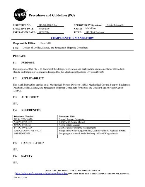
Procedures <strong>and</strong> Guidelines (<strong>PG</strong>)DIRECTIVE NO. <strong>540</strong>-<strong>PG</strong>-<strong>8700.2.1A</strong> APPROVED BY Signature: Original signed byEFFECTIVE DATE: 09/28/2009 NAME: Minh PhanEXPIRATION DATE: 09/28/2014 TITLE: <strong>540</strong> Chief EngineerCOMPLIANCE IS MANDATORYResponsible Office: Code <strong>540</strong>Title: Design of Dollies, St<strong>and</strong>s, <strong>and</strong> Spacecraft Shipping ContainersPREFACEP.1 PURPOSEThe purpose of this <strong>PG</strong> is to document the design, fabrication <strong>and</strong> certification requirements for all Dollies,St<strong>and</strong>s, <strong>and</strong> Shipping Containers designed by the Mechanical Systems Division (MSD)P.2 APPLICABILITYThis work instruction applies to all Mechanical System Division (MSD) Mechanical Ground Support Equipment(MGSE) Dollies, St<strong>and</strong>s, <strong>and</strong> Spacecraft Shipping Containers for uses at the Goddard Space Flight Center(GSFC).P.3 AUTHORITYN/AP.4 REFERENCESDocument Number<strong>NASA</strong> STD 5005B<strong>540</strong>-<strong>PG</strong>-8715.1.2B500-<strong>PG</strong>-8715.1.2541-<strong>PG</strong>-8072.1.2AAFSPCMAN 91-701 Vol. 3MIL-HDBK-1791Document TitleGround Support EquipmentGSFC MSD Safety ManualAETD Safety ManualGSFC Fastener Integrity RequirementsRange Safety Users Requirements, Launch Vehicles, Payloads & GSEDesigning for Internal Aerial Delivery in Fixed Wing AircraftP.5 CANCELLATIONN/AP.6 SAFETYN/ACHECK THE GSFC DIRECTIVES MANAGEMENT SYSTEM AThttp://gdms.gsfc.nasa.gov/gdmsnew/home.jsp TO VERIFY THAT THIS IS THE CORRECT VERSION PRIOR TO USE.GSFC 3-18 (7/06)
DIRECTIVE NO. <strong>540</strong>-<strong>PG</strong>-<strong>8700.2.1A</strong> Page 2 of 9EFFECTIVE DATE: 09/28/2009EXPIRATION DATE: 09/28/2014P.7 TRAININGN/AP.8 RECORDS* NRRS – <strong>NASA</strong> Records Retention Schedule (NPR 1441.1)Record Title Record Custodian RetentionStress Analysis Hardware Owner 5 Yrs or until Project CompletionTipping Analysis Hardware Owner 5 Yrs or until Project CompletionProof Test Hardware Owner 5 Yrs or until Project CompletionNDT Report Hardware Owner 5 Yrs or until Project CompletionP.9 METRICSN/AP.10 DEFINITIONSCatastrophicHazardCritical FastenerCritical WeldNDT (Non-Destructive Test)PayloadA condition in which a failure can result in disabling or fatal personnel injury, the loss of aspacecraft or launch vehicle.A fastener where the single failure would result in a Catastrophic HazardA weld where the single failure of which could result in disabling or fatal personnel injury ordamage to property or flight hardware.The development <strong>and</strong> application of technical methods to examine materials or components inways that do not impair future usefulness <strong>and</strong> serviceability in order to detect, locate, measure<strong>and</strong> evaluate flaws; to assess integrity, properties <strong>and</strong> composition; <strong>and</strong> to measure geometricalcharacteristics.Any flight hardware supported by MGSEP.11 ACRONYMSDLL Design Limit LoadFS Factor of SafetyGSFC Goddard Space Flight CenterOEM Original Equipment ManufacturerMGSE Mechanical Ground Support EquipmentMS Margin of SafetyS/C SpacecraftCHECK THE GSFC DIRECTIVES MANAGEMENT SYSTEM AThttp://gdms.gsfc.nasa.gov/gdmsnew/home.jsp TO VERIFY THAT THIS IS THE CORRECT VERSION PRIOR TO USE.GSFC 3-18 (7/06)
DIRECTIVE NO. <strong>540</strong>-<strong>PG</strong>-<strong>8700.2.1A</strong> Page 3 of 9EFFECTIVE DATE: 09/28/2009EXPIRATION DATE: 09/28/2014PROCEDURESIn this document, a requirement is identified by “shall,” a good practice by “should,” permission by“may” or “can,” expectation by “will,” <strong>and</strong> descriptive material by “is.”DESIGN/ANALYSISD.1 Load Requirements:All hardware shall be designed with the minimum design factors listed in Table 1. For hardware that willbe utilized outside GSFC at other sites (i.e. Kennedy Space Center, V<strong>and</strong>enberg, etc.) the designrequirements from these operational centers shall be identified early in the design process. It should benoted that if the requirements from these other sites are more restrictive than those contained herein,then they take precedence.Table 1. Design Load Factors, Factors of Safety <strong>and</strong> Test FactorsItemMGSEDolly 1 (rolling on casters/airpads)Static St<strong>and</strong>/Dolly 1 (Stationaryon casters, jacks)Turnover Dolly 1 (Stationary onDesign Limit Loads (DLL) G's Factor of Safety Initial TestFactorsVertical Lateral Long. Tipping 6 Ultimate Yield-1.0 ± 0.1 ± 0.1 0.5 5 3 2 x Payload-1.0 ± 0.1 ± 0.1 0.5 5 3 2 x Payload-1.0 ± 0.1 ± 0.1 0.5 5 3 2 x Payloadcasters, jacks)Transportation Dolly <strong>and</strong> S/CShipping Container(C-5) 7 -3.6/+1.62 ±1.0 3 +2/-1 3 N/A 4 3 2 1.25 x DLLTransportation Dolly <strong>and</strong> S/CShipping Container 1 (Air-ridevan)-3.0/+1.0 ± 1.0 ± 1.5 N/A 4 3 2 1.25 x DLLPersonnel Stationary WorkSt<strong>and</strong> 1,5 -1.0 ± 0.1 ± 0.1 0.5 5 3 2 x PayloadFLT Hwd/MGSE I/FDolly 1 (rolling on casters) -1.6 ± 0.25 ± 0.25 N/A 1.4 1.25 1.25 x DLLStatic St<strong>and</strong>/Dolly 1 (Stationaryon jacks)-1.0 ± 0.1 ± 0.1 N/A 1.4 1.25 1.25 x DLLTransportation Dolly <strong>and</strong> S/CShipping Container 7 (C-5)-3.6/+1.6 2 ± 1.0 3 +2/-1 3 N/A 1.5 1.25 1.25 x DLLTransportation Dolly <strong>and</strong> S/CShipping Container 1 (Air-ridevan)-1.0(±)2.0 ± 1.0 ± 1.5 N/A 1.4 1.25 1.25 x DLL1 Vertical load should be combined simultaneously with lateral then longitudinal loads (Vertical DLL + Lateral DLL, Vertical DLL + Longitudinal DLL)2 The Vertical load factors defined as -4.5/+2 g’s in MIL-HDBK-1791are yield load factorsCHECK THE GSFC DIRECTIVES MANAGEMENT SYSTEM AThttp://gdms.gsfc.nasa.gov/gdmsnew/home.jsp TO VERIFY THAT THIS IS THE CORRECT VERSION PRIOR TO USE.GSFC 3-18 (7/06)
DIRECTIVE NO. <strong>540</strong>-<strong>PG</strong>-<strong>8700.2.1A</strong> Page 4 of 9EFFECTIVE DATE: 09/28/2009EXPIRATION DATE: 09/28/20143 The Lateral <strong>and</strong> Longitudinal load factors defined as +/- 1.5 <strong>and</strong> +3/-1.5 in MIL-HDBK-1791 are Ultimate Load Factors <strong>and</strong> contain a 1.5 ultimateFactor of Safety. Also, the “+” for Longitudinal direction denotes forward <strong>and</strong> “-“ denotes the aft direction.4 Dolly is assumed to be secured to the base frame while shipping container is assumed to be secured to the tractor trailer/C-5.5 A minimum load of a) 250 lb per person shall be used or b) an evenly distributed load of 50 pound per square foot over the total area of the st<strong>and</strong>.6 For tipping, analysis an ultimate Factor of Safety of 1.0 may be used.7 Loads to be applied independently, single direction at a timeNote:I. The current Western Range Safety Document (Ref. AFSPCMAN 91-701 V3) specifies seismic loading requirements as 0.4 g’s vertical <strong>and</strong> 2.0 g’slateralII. Minus sign denotes downward for the vertical load. Also, vertical loads include gravity (-1g).III. Design Limit Loads applied through system Center of gravityD.2 Strength AnalysisA stress analysis shall be prepared for all Dollies, S/C Shipping Containers <strong>and</strong> Personnel Work St<strong>and</strong>s. Theanalysis shall calculate stress <strong>and</strong>/or load levels in all loaded components <strong>and</strong> tabulate margins of safety (MS)based on material allowable strengths or load capability.MS = [Allowable stress (or Load) / ( F.S. x Induced Stress (or Load)] - 1The stress analysis of the dolly must include the dolly’s own weight, not just the added payload weightD.3 Tipping AnalysisA tipping analysis shall be prepared for all dollies <strong>and</strong> work st<strong>and</strong>s. The tipping DLL shown in Table 1shall be applied to the Center of Gravity (CG) of the system in the worse case configuration. For theanalysis, a Factor of Safety of 1.0 may be used in the tipping MS calculation.D.4 Seismic AnalysisHardware that will be used outside Goddard in areas susceptible to earthquakes such as the WesternRange (WR, V<strong>and</strong>enberg Air Force Base), seismic loading shall be considered. The current seismicloading requirements for the WR are specified in AFSPCMAN 91-710 V3 are: 0.4g’s vertical <strong>and</strong> 2.0g’s lateral. For the analysis, a Factor of Safety of 1.0 may be used in the MS calculations.D.5 Single Point Failure (Critical) WeldAll critical welds shall have a surface NDT (magnetic particle or dye penetrant) performed before <strong>and</strong>after the initial proof test <strong>and</strong> after the periodic proof test. During the detail design of the hardware,critical welds should be avoided where possible. If critical welds are present in the design, they shouldnot be painted so that surface NDT may be performed.Though not required, a safe life analysis should be considered for all S/C shipping containers <strong>and</strong>transportation dollies due to their high cyclic loading. More consideration should be given to performingthis analysis on hardware that is being reused by a program that didn’t actually develop the hardware inthe first place. When performing this analysis a 4X service life shall be demonstrated.CHECK THE GSFC DIRECTIVES MANAGEMENT SYSTEM AThttp://gdms.gsfc.nasa.gov/gdmsnew/home.jsp TO VERIFY THAT THIS IS THE CORRECT VERSION PRIOR TO USE.GSFC 3-18 (7/06)
DIRECTIVE NO. <strong>540</strong>-<strong>PG</strong>-<strong>8700.2.1A</strong> Page 5 of 9EFFECTIVE DATE: 09/28/2009EXPIRATION DATE: 09/28/2014D.6 Critical FastenersAll critical fasteners used on the hardware need to be identified <strong>and</strong> are subjected to the GSFC FastenerIntegrity Requirements (541-<strong>PG</strong>-8072.1.2). During the detail design of the hardware, critical fastenersshould be avoided <strong>and</strong> fail safe fastener patterns used where possible.D.7 Proof Testing FrequencyAll new or modified hardware shall be proof tested to the levels specified in Table 1. The hardware shallbe re-proofed every 4 years unless adequate documentation is provided to the <strong>540</strong> chief engineerverifying the appropriate h<strong>and</strong>ling, storage, <strong>and</strong> maintenance of the hardware.Following all proof testing <strong>and</strong> prior to use, all hardware shall be visually inspected for any damage oranomalous conditions.D.8 Hardware TestsD.8.1 Dolly (rolling on casters/air pads) Vertical Proof TestThe vertical strength of the dolly while on its casters/air pads shall be demonstrated through a verticalproof test performed with 2 times the payload mass attached to the interface.. With the proof massesattached, the dolly shall be moved around the facilities while on its castors/air pads.D.8.2 Dolly (rolling on casters/air pads) Lateral Proof TestThe strength of the dolly while on its castors/air pads in the lateral <strong>and</strong> longitudinal directions shall bedemonstrated through test or analysis using the DLL <strong>and</strong> Factors of Safety specified in Table 1.D.8.3 Static St<strong>and</strong>/Dolly (Stationary on jacks) Vertical Proof TestThe vertical strength of the Static St<strong>and</strong>/Dolly (stationary on its jacks) shall be demonstrated through avertical proof test performed with 2 times the payload mass attached to the interface plane.D.8.4 Static St<strong>and</strong>/Dolly (Stationary on jacks/wheels) Lateral Proof TestThe strength of the dolly while on its castors/air pads in the lateral <strong>and</strong> longitudinal directions shall bedemonstrated through test or analysis using the DLL <strong>and</strong> Factors of Safety specified in Table 1.D.8.5 Static St<strong>and</strong>/Dolly (Stationary on jacks/wheels) Tipping Proof TestThe resistance of the Static St<strong>and</strong>/Dolly (stationary on its jacks/wheels) to tipping in the highest cgorientation shall be demonstrated through test or analysis using the DLL <strong>and</strong> Factors of Safety specifiedin Table 1. For the analysis, a Factor of Safety of 1.0 may be used in the tipping MS calculation.D.8.6 Turnover Dolly (Stationary on jacks) Dynamic Rotational Proof TestThe strength of the rotational mechanism of the dolly while on its jacks shall be demonstrated through aproof test with 2 times the payload mass attached to the interface plane at the same cg location as thepayload (twice the interface moment).. The rotational mechanism shall be operated through the fullrange of motion <strong>and</strong> at the maximum operational rotational speeds.CHECK THE GSFC DIRECTIVES MANAGEMENT SYSTEM AThttp://gdms.gsfc.nasa.gov/gdmsnew/home.jsp TO VERIFY THAT THIS IS THE CORRECT VERSION PRIOR TO USE.GSFC 3-18 (7/06)
DIRECTIVE NO. <strong>540</strong>-<strong>PG</strong>-<strong>8700.2.1A</strong> Page 6 of 9EFFECTIVE DATE: 09/28/2009EXPIRATION DATE: 09/28/2014D.8.7 Turnover Dolly (Stationary on jacks) Lateral Proof TestThe strength of the dolly while in the lateral <strong>and</strong> longitudinal directions shall be demonstrated throughtest or analysis using the DLL <strong>and</strong> Factors of Safety specified in Table 1.D.8.8 Turnover Dolly (Stationary on jacks) Tipping Proof Test.The resistance of the turnover dolly <strong>and</strong> payload to tipping while on its jacks in the highest cgorientation shall be demonstrated through test or analysis using the DLL <strong>and</strong> Factors of Safety specifiedin Table 1. For the analysis, a Factor of Safety of 1.0 may be used in the tipping MS calculation.D.8.9 Transportation Dolly <strong>and</strong> S/C Shipping Container (C-5) Proof TestThe Transportation Dolly <strong>and</strong> Shipping Container while supported at their transport interfaces shall beproof tested to the system mass (payload + dolly) times the DLLs specified in Table 1 with a test factorof 1.25. For the test, the maximum payload mass shall be assumed. As a minimum, a test demonstratingthe strength in the vertical direction shall be performed. The lateral <strong>and</strong> longitudinal strength may bedemonstrated by analysis if positive Margins of Safety using higher Factors of Safety of 3 on yield <strong>and</strong> 5on ultimate can be shown.D.8.10 Transportation Dolly <strong>and</strong> S/C Shipping Container (Air-ride van) Proof TestThe Transportation Dolly <strong>and</strong> Shipping Container while supported at their transport interfaces shall beproof tested to the system mass (payload + dolly) times the DLLs specified in Table 1 with a test factorof 1.25. For the test, the maximum payload mass shall be assumed. As a minimum, a test demonstratingthe strength in the vertical direction shall be performed. The lateral <strong>and</strong> longitudinal strength may bedemonstrated by analysis if positive Margins of Safety using higher Factors of Safety of 3 on yield <strong>and</strong> 5on ultimate can be shown. In addition to the static proof testing, the Transport Dolly <strong>and</strong> ShippingContainer shall be road tested (with a maximum payload mass attached) over similar roads that the flightpayload will be transported over. For the road test, three axis acceleration responses at the base of thecontainer <strong>and</strong> on the isolated Transportation Dolly shall be recorded.D.8.11 Personnel Work St<strong>and</strong> (Stationary) Vertical Proof TestA vertical proof test of the Personnel Work St<strong>and</strong> shall be performed to the levels specified in Table 1.D.8.12 Personnel Work St<strong>and</strong> (Stationary) Tipping Proof TestTipping resistance of Personnel Work St<strong>and</strong>s shall be demonstrated by test or through analysis using theDLL <strong>and</strong> Factors of Safety specified in Table 1. For the analysis, a Factor of Safety of 1.0 may be usedin the tipping MS calculationD.8.13 Spacecraft/Dolly Interface (Rolling on casters/air pads) Proof TestingThe S/C side of the S/C-Dolly interface shall be tested to the levels specified in Table 1. If the spacecraftside of the interface is not test verified then positive Margins of Safety must be demonstrated withhigher Factors of Safety of 2.0 on yield <strong>and</strong> 2.6 on ultimate. GSE interfaces that utilize bonded joints aspart of the load path must be proof tested <strong>and</strong> cannot show verification by analysis only.CHECK THE GSFC DIRECTIVES MANAGEMENT SYSTEM AThttp://gdms.gsfc.nasa.gov/gdmsnew/home.jsp TO VERIFY THAT THIS IS THE CORRECT VERSION PRIOR TO USE.GSFC 3-18 (7/06)
DIRECTIVE NO. <strong>540</strong>-<strong>PG</strong>-<strong>8700.2.1A</strong> Page 7 of 9EFFECTIVE DATE: 09/28/2009EXPIRATION DATE: 09/28/2014D.8.14 Spacecraft/Dolly Interface (Stationary) Proof TestingThe S/C side of the S/C-Dolly interface shall be tested to the levels specified in Table 1. If the spacecraftside of the interface is not test verified then positive margins of safety must be demonstrated with higherfactors of safety of 2.0 on yield <strong>and</strong> 2.6 on ultimate. GSE interfaces that utilize bonded joints as part ofthe load path must be proof tested <strong>and</strong> cannot show verification by analysis only.D.8.15 Spacecraft/Transportation Dolly (C5) MGSE Interface Proof Testing.The spacecraft interface that attaches to the Transportation Dolly (C5) shall be proof tested to the levelsspecified in Table 1 with a test factor of 1.25. If the spacecraft side of the interface is not test verifiedthen positive margins of safety must demonstrated with higher factors of safety of 2.0 on yield <strong>and</strong> 2.6on ultimate. GSE interfaces that utilize bonded joints as part of the load path must be proof tested <strong>and</strong>cannot show verification by analysis only.D.8.16 Spacecraft/Transportation Dolly (Air-ride) MGSE Interface Proof TestingThe spacecraft interface that attaches to Transportation Dolly (Air-ride) shall be proof tested to the DLLspecified in Table 1 with a test factor of 1.25. If the spacecraft side of the interface is not test verifiedthen positive margins of safety must demonstrated with higher factors of safety of 2.0 on yield <strong>and</strong> 2.6on ultimate. GSE interfaces that utilize bonded joints as part of the load path must be proof tested <strong>and</strong>cannot show verification by analysis only.D.8.17 Separable AssembliesAny portion of the hardware assembly that will be disassembled after Proof Testing shall betagged/marked in some manner so that it shall be reassembled identically to the tested configuration.D.9 Best PracticesThe following guidelines for the selection of materials, components <strong>and</strong> use of design rules for dollies<strong>and</strong> work platforms assemblies are recommended.1. Load lines should align so that local induced moments are avoided. Lines of action shouldintersect at the neutral axes of the members.2. All bolted joints should be designed fail-safe where the highest loaded fastener in the pattern canbe removed <strong>and</strong> the remaining fasteners can carry the load with a 1.0 factor of safety. If the jointis not fail-safe, then some method will be needed to ensure that if the fasteners are removedfollowing the proof test, the bolts are indexed to the appropriate joints.3. Where possible, all welds should be designed fail safe.4. For structural elements, materials with good strain properties should be used. It should be notedthat the current Range Safety Document (AFSPCMAN 91-710 V3) specifies that, “materialsthat have at least 20% ultimate strain need to be used. If the materials selected do not meet thisminimum ultimate strain requirement, the design must include a fracture mechanics analysis thatshows a service life cycle factor of safety of 100:1 <strong>and</strong> a detailed NDE surface <strong>and</strong>/or volumetricrequirements.”CHECK THE GSFC DIRECTIVES MANAGEMENT SYSTEM AThttp://gdms.gsfc.nasa.gov/gdmsnew/home.jsp TO VERIFY THAT THIS IS THE CORRECT VERSION PRIOR TO USE.GSFC 3-18 (7/06)
DIRECTIVE NO. <strong>540</strong>-<strong>PG</strong>-<strong>8700.2.1A</strong> Page 8 of 9EFFECTIVE DATE: 09/28/2009EXPIRATION DATE: 09/28/20145. If the hardware will be utilized inside a thermal vacuum chamber during testing, boxbeams/closed sections should be avoided. It is difficult to properly clean the inside surfaces ofbox beams <strong>and</strong> box beam weldments can result in virtual leaks if not properly vented.6. Shock Isolation Target Frequency - Target frequency for the shock isolation system should be inthe 3 - 7 Hz range to avoid coupling with dynamic inputs from air-ride trucks (10Hz) <strong>and</strong> C5 aircraft (>10 Hz). Where possible, testing of the isolation system with aspacecraft mass (<strong>and</strong> center of gravity) simulator under transportation conditions should beperformed to verify environments <strong>and</strong> performance of the isolation system prior to use with theflight hardware.7. If alignment measurements are planned on the Dolly, consider incorporating a 3 point levelingjack configuration to aid alignment set-up.8. Use swivel hoists in place of lifting eyes where ever possible due to the lack of lateral loadcapability of lifting eyes. Utilize some method of securing nuts so they don’t come loose duringtransportation9. If lifting lugs are permanently attached (welded), only visual inspection will be applicable.10. Provide dedicated grounding points (tapped holes) around the Dolly.11. Dolly Caster Loading. To determine the caster loading on a dolly, an assumption of the dollystiffness needs to be made. If the four wheeled dolly is very stiff out of plane, while the dolly isrolled across an uneven floor, only three wheels will contact the floor at a time <strong>and</strong> if the cg isclose to the center of the footprint of the wheels, only two diagonal wheels will carry load. If thedolly stiffness is not known, the conservative loading assumption that only two diagonal casterscarry the load should be made. If this assumption is felt to be too conservative for the dollyconfiguration, then FEM analysis using worst-case assumptions for payload weight <strong>and</strong> CGlocation can be used to determine the load sharing of the casters.For example, let’s say we have a dolly that has an empty weight of 1000 lbs <strong>and</strong> is sized to carrya 1000 lbs payload. If the dolly is very stiff out of plane, casters rated for at least 1000 lbs shouldbe used. If the dolly is very flexible out of plane (like a Flotron dolly) casters rated for at least500 lbs should be used. Please note that for this example the effect of the 0.1g lateral load hasnot been included for simplicity. The actual castor rated load should account for a combinedloading condition as specified in Table 1.When sizing the casters, the caster manufacturer needs to be contacted to determine what Factorsof Safety the vendor used in their design. If the vendor did not use Factors of Safety of 3 <strong>and</strong> 5(yield <strong>and</strong> ultimate) the casters need to be derated proportionally. Also, the vendor should becontacted if the proof test will exceed the rated load of the caster for the vendor’s concurrence.CHECK THE GSFC DIRECTIVES MANAGEMENT SYSTEM AThttp://gdms.gsfc.nasa.gov/gdmsnew/home.jsp TO VERIFY THAT THIS IS THE CORRECT VERSION PRIOR TO USE.GSFC 3-18 (7/06)
DIRECTIVE NO. <strong>540</strong>-<strong>PG</strong>-<strong>8700.2.1A</strong> Page 9 of 9EFFECTIVE DATE: 09/28/2009EXPIRATION DATE: 09/28/2014CHANGE HISTORY LOGRevision Effective Date Description of ChangesBaseline 12/10/2007 Initial ReleaseA 09/28/2009 Revised Table 1. Removed requirement for adding an additional1x mass equal to the dolly empty weight for the proof test. Addeddiscussion in section D. 9 on caster sizingCHECK THE GSFC DIRECTIVES MANAGEMENT SYSTEM AThttp://gdms.gsfc.nasa.gov/gdmsnew/home.jsp TO VERIFY THAT THIS IS THE CORRECT VERSION PRIOR TO USE.GSFC 3-18 (7/06)