Machine Vision Illumination Catalog, Vol 001
Machine Vision Illumination Catalog, Vol 001
Machine Vision Illumination Catalog, Vol 001

You also want an ePaper? Increase the reach of your titles
YUMPU automatically turns print PDFs into web optimized ePapers that Google loves.
Fiber Optic Light Sources<br />
and Light Guides<br />
Cold<strong>Vision</strong> Series<br />
Fiber Characteristics<br />
Fiber Composition<br />
Most optical fibers consist of two different types of optically<br />
transmittive materials. The core, about 75-90% of the fiber depending<br />
on the fiber diameter, has a higher refractive index than the cladding.<br />
This creates a reflecting interface between core and cladding which<br />
keeps the light within the core due to total reflection.<br />
Most optical fibers are made from glass, plastic or synthetic fused silica<br />
(often refered to as "quartz"). Each fiber has different properties<br />
producing various advantages. Due to their low attenuation silica fibers<br />
are commonly used in data communication. Glass is still the best<br />
choice for illumination and sensing applications, due to a reasonale<br />
cost-benefit ratio. Plastic fibers can be used for assemblies not<br />
requiring heat above 175°F/80°C. Single plastic fibers are usually larger<br />
in diameter than glass fibers, which results in restricted bending radii.<br />
Fiber Characteristics<br />
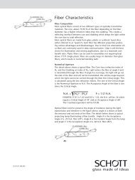
Numerical Aperture<br />
The sketch above shows a typical fiber. The core has a refractive index<br />
of N1 and the cladding an index of N2. Light enters the fiber at angle<br />
A and is transmitted through the fiber. If the angle A is too large, the<br />
light will not be transmitted. We call the angle beyond which the light<br />
cannot be carried through the fiber the Critical Angle. This is<br />
calculated using the two refraction indices. The sine of the Critical<br />
Angle is the Numerical Aperture or NA The Acceptance Angle of the<br />
fiber is two times the Critical Angle.<br />
NA =<br />
(N 1)<br />
2 - (N )<br />
2 2<br />
f # = 1/2 NA<br />
EXAMPLE: If N1 is 1.62 and N2 is 1.52, the NA will be .56 which<br />
equals a Critical Angle of 34° and an Acceptance Angle of 68°.<br />
The f number/equivalent will be f/0.89.<br />
Optical fibers tend to preserve the angle of incidence during the light<br />
transmission and therefore in the figure above, the angle A is shown at<br />
both the entrance and exit ends of the fiber. The sketch below shows a<br />
typical projecting lamp illuminating a fiber bundle. The angle A is the<br />
Acceptance Angle of a .25 NA fiber (29°). Angle B is the Incident Angle<br />
from the lamp and angle C is the Acceptance Angle of a .66 NA fiber<br />
(83°).<br />
i-196