Dometic Duotherm Brisk Air Conditioner, Heat Pump, Penguin ...
Dometic Duotherm Brisk Air Conditioner, Heat Pump, Penguin ...
Dometic Duotherm Brisk Air Conditioner, Heat Pump, Penguin ...
- No tags were found...

You also want an ePaper? Increase the reach of your titles
YUMPU automatically turns print PDFs into web optimized ePapers that Google loves.
INSTALLATION INSTRUCTIONS DUCTED CCC<br />
RECORD THIS UNIT INFORMATION FOR<br />
FUTURE REFERENCE:<br />
Model Number<br />
Serial Number<br />
Date Purchased<br />
USA<br />
SERVICE OFFICE<br />
<strong>Dometic</strong> Corporation<br />
509 South Poplar St.<br />
LaGrange, IN 46761<br />
260-463-4858<br />
CANADA<br />
<strong>Dometic</strong> Distribution<br />
866 Langs Drive<br />
Cambridge, Ontario<br />
CANADA N3H 2N7<br />
519-653-4390<br />
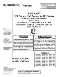
579 Series BRISK AIR<br />
590 Series BRISK AIR<br />
591 Series HEAT PUMP<br />
595 Series QUICK COOL<br />
600 Series PENGUIN<br />
630 Series PENGUIN<br />
Roof Top <strong>Air</strong> <strong>Conditioner</strong>s & <strong>Heat</strong> <strong>Pump</strong>s<br />
Used With Part No. 3109226.005 & 3109407.001<br />
Comfort Control Center Electronic Control Kit<br />
Ducted<br />
THIS UNIT IS DESIGNED FOR OEM INSTALLATION<br />
ALL INITIAL INSTALLATIONS MUST BE APPROVED BY THE DOMETIC CORP.<br />
! WARNING<br />
! AVERTISSEMENT<br />
For Service Center<br />
Assistance Call:<br />
800-544-4881<br />
C<br />
US<br />
This manual must be read and understood<br />
before installation, adjustment,<br />
service, or maintenance is<br />
performed. This unit must be installed<br />
by a qualified service technician.<br />
Modification of this product<br />
can be extremely hazardous and<br />
could result in personal injury or<br />
property damage.<br />
INSTALLATION<br />
INSTRUCTIONS<br />
57908.321<br />
57908.521<br />
57912.621<br />
57912.622<br />
57912.631<br />
57915.322<br />
57915.331<br />
57915.421<br />
57915.422<br />
57915.521<br />
57915.522<br />
Lire et comprendre ce manuel avant de<br />
procéder à l'installation, à des réglages,<br />
de l'entretien ou des réparations.<br />
L'installation de cet appareil doit être<br />
effectuée par un réparateur qualifié.<br />
Toute modification de cet appareil peut<br />
être extrêmement dangereuse et<br />
entraîner des blessures ou dommages<br />
matériels.<br />
57915.531<br />
57915.536<br />
57915.541<br />
57915.546<br />
57915.621<br />
57915.622<br />
57915.631<br />
59016.621<br />
59136.321<br />
59136.331<br />
59136.521<br />
MODELS<br />
59136.531<br />
59136.536<br />
59136.621<br />
59136.631<br />
59516.303<br />
59516.331<br />
59516.336<br />
59516.501<br />
59516.531<br />
59516.536<br />
59516.601<br />
59516.603<br />
59516.631<br />
59528.601<br />
59529.531<br />
59529.601<br />
59529.631<br />
59530.531<br />
59530.532<br />
59530.536<br />
59530.601<br />
59530.631<br />
59530.632<br />
600312.321<br />
600315.326<br />
600312.421<br />
600315.321<br />
600315.421<br />
630035.321<br />
630035.421<br />
REVISION<br />
Form No. 3109270.060 11/03<br />
(Replaces 3109270.052)<br />
(French 3109537.055)<br />
©2003 <strong>Dometic</strong> Corporation<br />
LaGrange, IN 46761<br />
Important: These instructions must stay with<br />
unit. Owner read carefully.<br />
1
INSTALLATION INSTRUCTIONS DUCTED CCC<br />
SAFETY INSTRUCTIONS<br />
This manual has safety information and instructions<br />
to help users eliminate or reduce the risk of<br />
accidents and injuries.<br />
RECOGNIZE SAFETY INFORMATION<br />
This is the safety-alert symbol. When you see this<br />
symbol in this manual, be alert to the potential for<br />
personal injury.<br />
Follow recommended precautions and safe operating<br />
instructions.<br />
UNDERSTAND SIGNAL WORDS<br />
A signal word , WARNING OR CAUTION is used<br />
with the safety-alert symbol. They give the level of<br />
risk for potential injury.<br />
!<br />
indicates a potentially hazardous<br />
situation which, if not avoided, could result in<br />
death or serious injury.<br />
!<br />
WARNING<br />
CAUTION<br />
indicates a potentially hazardous<br />
situation which, if not avoided may result in<br />
minor or moderate injury.<br />
CAUTION<br />
!<br />
used without the safety alert<br />
symbol indicates, a potentially hazardous situation<br />
which, if not avoided may result in property<br />
damage.<br />
Read and follow all safety information and instructions.<br />
1. GENERAL INFORMATION<br />
A. Product features or specifications as described or illustrated<br />
are subject to change without notice.<br />
B. This air conditioner is designed for:<br />
1. Installation on a recreational vehicle at the time the<br />
vehicle is manufactured.<br />
2. Mounting on the roof of a recreational vehicle.<br />
3. Connection to an air distribution system located in<br />
the ceiling/roof cavity of the recreational vehicle.<br />
4. Roof construction with rafters/joists on minimum of<br />
16 inch centers.<br />
5. Minimum of 2.00" and maximum of 5.50" distance<br />
between roof to ceiling of recreational vehicle. Alternate<br />
installation methods will allow for roofs more<br />
than 5.50" thick.<br />
C. The ability of the air conditioner to maintain the desired<br />
inside temperature depends on the heat gain of the RV.<br />
Some preventative measures taken by the occupants of<br />
the RV can reduce the heat gain and improve the<br />
performance of the air conditioner. During extremely high<br />
outdoor temperatures, the heat gain of the vehicle may<br />
be reduced by:<br />
1. Parking the RV in a shaded area<br />
2. Using window shades (blinds and/or curtains)<br />
3. Keeping windows and doors shut or minimizing<br />
usage<br />
4. Avoiding the use of heat producing appliances.<br />
Operation on High Fan/Cooling mode will give optimum or<br />
maximum efficiency in high humidity or high outside temperatures.<br />
Starting the air conditioner early in the morning and giving it<br />
a "head start" on the expected high outdoor ambient will<br />
greatly improve its ability to maintain the desired indoor<br />
temperature.<br />
For a more permanent solution to high heat gain, accessories<br />
like A&E outdoor patio and window awnings will reduce<br />
heat gain by removing the direct sun. They also add a nice<br />
area to enjoy company during the cool of the evening.<br />
D. Condensation<br />
Note: The manufacturer of this air conditioner will not be<br />
responsible for damage caused by condensed moisture on<br />
ceilings or other surfaces. <strong>Air</strong> contains moisture and this<br />
moisture tends to condense on cold surfaces. When air<br />
enters the RV, condensed moisture may appear on the<br />
ceiling, windows, metal parts, etc. The air conditioner removes<br />
this moisture from the air during normal operation.<br />
Keeping doors and windows closed when this air conditioner<br />
is in operation will minimize condensed moisture on cold<br />
surfaces.<br />
2
INSTALLATION INSTRUCTIONS DUCTED CCC<br />
SPECIFICATIONS<br />
MODEL NOMINAL ELECTRICAL COMPRESSOR COMPRESSOR FAN MOTOR FAN MOTOR SCFM-HIGH TOTAL REFRIGERANT MINIMUM AC CIRCUIT INSTALLED MINIMUM<br />
NO. CAPACITY RATING RATED LOAD LOCKED RATED LOAD LOCKED SPEED STATIC R-22 (OZ) WIRE SIZE* PROTECTION WEIGHT GENERATOR<br />
(BTU/HR) AMPS ROTOR AMPS ROTOR MAX/MIN MAX/MIN *** USER (POUNDS) SIZE**<br />
COOLING AMPS AMPS “ W. C. SUPPLIED 1 UNIT/ 2 UNITS<br />
57908.321 7,180 115VAC,<br />
6.9 36.0 2.5 5.8 325 / 250 0.55 / 0.90 16.0 12 AWG 20 Amp 75 2.5 KW / 4.0 KW<br />
57908.521 7,100 60 HZ., 1PH. 6.6 34.0 2.5 5.8 325 / 250 0.55 / 0.90 17.0 Copper 20 Amp 75 2.5 KW / 4.0 KW<br />
57912.321 11,000 9.5 53.0 2.5 5.8 325 / 250 0.55 / 0.90 15.5 up to 24’ 20 Amp 94 2.5 KW / 4.0 KW<br />
57912.531 11,000 8.0 53.0 2.5 5.8 325 / 250 0.55 / 0.90 18.5 20 Amp 94 2.5 KW / 4.0 KW<br />
57912.621 11,000 8.5 48.3 2.5 5.8 325 / 250 0.55 / 0.90 16.0 20 Amp 94 2.5 KW / 4.0 KW<br />
57912.622 11,000 8.5 48.3 2.5 5.8 325 / 250 0.55 / 0.90 18.0 20 Amp 94 2.5 KW / 4.0 KW<br />
57912.631 11,000 8.5 48.3 2.5 5.8 325 / 250 0.55 / 0.90 18.0 20 Amp 94 2.5 KW / 4.0 KW<br />
57915.321 13,500 12.1 60.0 2.5 5.8 325 / 250 0.55 / 0.90 15.0 20 Amp 104 3.5 KW / 5.0 KW<br />
57915.322 13,500 11.4 58.0 2.5 5.8 325 / 250 0.55 / 0.90 15.5 20 Amp 104 3.5 KW / 5.0 KW<br />
57915.331 13,500 11.4 58.0 2.5 5.8 325 / 250 0.55 / 0.90 15.5 20 Amp 100 3.5 KW / 5.0 KW<br />
57915.421 13,500 11.5 50.0 2.5 5.8 325 / 250 0.55 / 0.90 13.5 20 Amp 100 3.5 KW / 5.0 KW<br />
57915.422 13,500 11.5 50.0 2.5 5.8 325 / 250 0.55 / 0.90 14.5 20 Amp 100 3.5 KW / 5.0 KW<br />
57915.521 13,500 12.1 59.0 2.5 5.8 325 / 250 0.55 / 0.90 16.0 20 Amp 94 3.5 KW / 5.0 KW<br />
57915.522 13,500 12.1 59.0 2.5 5.8 325 / 250 0.55 / 0.90 16.5 20 Amp 94 3.5 KW / 5.0 KW<br />
57915.531 13,500 12.1 59.0 2.5 5.8 325 / 250 0.55 / 0.90 16.5 20 Amp 94 3.5 KW / 5.0 KW<br />
57915.536 13,500 12.1 59.0 2.5 5.8 325 / 250 0.55 / 0.90 16.5 20 Amp 94 3.5 KW / 5.0 KW<br />
57915.541 13,500 11.3 62.0 2.5 5.8 325 / 250 0.55 / 0.90 16.0 20 Amp 94 3.5 KW / 5.0 KW<br />
57915.546 13,500 11.3 62.0 2.5 5.8 325 / 250 0.55 / 0.90 16.0 20 Amp 94 3.5 KW / 5.0 KW<br />
57915.621 13,500 11.0 54.4 2.5 5.8 325 / 250 0.55 / 0.90 16.0 20 Amp 94 3.5 KW / 5.0 KW<br />
57915.622 13,500 11.0 54.4 2.5 5.8 325 / 250 0.55 / 0.90 16.5 20 Amp 94 3.5 KW / 5.0 KW<br />
3<br />
57915.626 13,500 11.0 54.4 2.5 5.8 325 / 250 0.55 / 0.90 16.0 20 Amp 94 3.5 KW / 5.0 KW<br />
57915.631 13,500 11.0 54.4 2.5 5.8 325 / 250 0.55 / 0.90 16.5 20 Amp 94 3.5 KW / 5.0 KW<br />
57915.731 13,500 11.3 56.0 2.5 5.8 325 / 250 0.55 / 0.90 15.0 20 Amp 94 3.5 KW / 5.0 KW<br />
59016.521 15,000 12.9 71.0 2.5 6.0 350 / 250 0.40 /1.1 0 26.5 20 Amp 101 3.5 KW / 5.0 KW<br />
59016.526 15,000 12.9 71.0 2.5 6.0 350 / 250 0.40 / 1.10 26.5 20 Amp 104 3.5 KW / 5.0 KW<br />
59016.531 15,000 12.9 71.0 2.5 6.0 350 / 250 0.40 / 1.10 26.5 20 Amp 104 3.5 KW / 5.0 KW<br />
59016.621 15,000 12.9 77.0 2.5 6.0 350 / 250 0.40 / 1.10 26.5 20 Amp 101 3.5 KW / 5.0 KW<br />
59136.321 15,000 12.7 60.0 2.5 6.0 325 / 250 0.40 / 1.10 34.0 20 Amp 104 3.5 KW / 5.0 KW<br />
59136.521 15,000 12.9 71.0 25. 6.0 325 / 250 0.40 / 1.10 34.5 20 Amp 104 3.5 KW / 5.0 KW<br />
59136.531 15,000 12.8 79.0 2.5 6.0 325 / 250 0.40 / 1.10 31.5 20 Amp 105 3.5 KW / 5.0 KW<br />
59136.536 15,000 12.8 79.0 2.5 6.0 325 / 250 0.40 / 1.10 31.5 20 Amp 105 3.5 KW / 5.0 KW<br />
59136.621 15,000 12.0 77.0 2.5 6.0 325 / 250 0.40 / 1.10 34.5 20 Amp 105 3.5 KW / 5.0 KW<br />
59136.631 15,000 12.0 77.0 2.5 6.0 325 / 250 0.40 / 1.10 34.5 20 Amp 105 3.5 KW / 5.0 KW<br />
59516.303 15,000 12.7 60.0 2.0 5.6 325 / 250 0.40 / 1.10 29.0 20 Amp 104 3.5 KW / 5.0 KW<br />
59516.331 15,000 11.5 50.0 2.5 5.8 325 / 250 0.40 / 1.10 29.0 20 Amp 94 3.5 KW / 5.0 KW<br />
* For wire lengths over 24 ft. consult the National Electric Code for proper sizing.<br />
** <strong>Dometic</strong> Corporation gives GENERAL guidelines for generator requirements. These guidelines come from experiences people have had in actual applications<br />
When sizing the generator, the total power usage of your recreational vehicle must be considered. Keep in mind generators lose power at high altitudes and<br />
from lack of maintenance.<br />
*** CIRCUIT PROTECTION: Time Delay Fuse or HACR Circuit Breakers Required.
INSTALLATION INSTRUCTIONS DUCTED CCC<br />
SPECIFICATIONS<br />
MODEL NOMINAL ELECTRICAL COMPRESSOR COMPRESSOR FAN MOTOR FAN MOTOR SCFM-HIGH TOTAL REFRIGERANT MINIMUM AC CIRCUIT INSTALLED MINIMUM<br />
NO. CAPACITY RATING RATED LOAD LOCKED RATED LOAD LOCKED SPEED STATIC R-22 (OZ) WIRE SIZE* PROTECTION WEIGHT GENERATOR<br />
(BTU/HR) AMPS ROTOR AMPS ROTOR MAX/MIN MAX/MIN *** USER (POUNDS) SIZE**<br />
COOLING AMPS AMPS “ W. C. SUPPLIED 1 UNIT/ 2 UNITS<br />
59516.336 15,000 115VAC,<br />
12.7 60.0 2.0 5.6 325 / 250 0.40 / 1.10 29.0 12 AWG 20 Amp 94 3.5 KW / 5.0 KW<br />
59516.501 15,000 60 HZ., 1PH. 12.9 71.0 2.5 6.0 325 / 250 0.40 / 1.10 31.0 Copper 20 Amp 94 3.5 KW / 5.0 KW<br />
59516.506 15,000 12.9 71.0 2.5 6.0 325 / 250 0.40 / 1.10 31.0 up to 24’ 20 Amp 94 3.5 KW / 5.0 KW<br />
59516.531 15,000 11.5 50.0 2.5 5.8 325 / 250 0.40 / 1.10 26.5 20 Amp 94 3.5 KW / 5.0 KW<br />
59516.536 15,000 11.5 50.0 2.5 5.8 325 / 250 0.40 / 1.10 29 20 Amp 94 3.5 KW / 5.0 KW<br />
59516.601 15,000 12.9 77.0 2.5 6.0 350 / 250 0.40 / 1.10 31.0 20 Amp 102 3.5 KW / 5.0 KW<br />
59516.603 15,000 12.3 77.0 2.0 5.6 325 / 250 0.40 / 1.10 29.5 20 Amp 102 3.5 KW / 5.0 KW<br />
59516.606 15,000 12.9 71.0 2.5 6.0 325 / 250 0.40 / 1.10 31.0 20 Amp 94 3.5 KW / 5.0 KW<br />
59516.631 15,000 12.3 77.0 2.0 5.6 325 / 250 0.40 / 1.10 29.5 20 Amp 104 3.5 KW / 5.0 KW<br />
59528.601 N/A 6.0 45.6 2.0 5.6 325 / 250 0.40 / 1.10 16.5 15 Amp 92 3.5 KW / 5.0 KW<br />
59529.531 N/A 6.9 49.0 2.0 5.6 325 / 250 0.40 / 1.10 18.5 15 Amp 94 3.5 KW / 5.0 KW<br />
59529.601 N/A 8.0 48.3 2.0 5.6 325 / 250 0.40 / 1.10 19.0 15 Amp 94 3.5 KW / 5.0 KW<br />
59529.631 N/A 8.0 48.3 2.0 5.6 325 / 250 0.40 / 1.10 19.0 15 Amp 94 3.5 KW / 5.0 KW<br />
59530.531 N/A 7.8 53.0 2.0 5.6 325 / 250 0.40 / 1.10 19.0 15 Amp 94 3.5 KW / 5.0 KW<br />
59530.532 N/A 8.0 53.0 2.5 5.8 325 / 250 0.40 / 1.10 18.5 15 Amp 94 3.5 KW / 5.0 KW<br />
59530.536 N/A 7.8 53.0 2.0 5.6 325 / 250 0.40 / 1.10 19.0 15 Amp 94 3.5 KW / 5.0 KW<br />
59530.601 N/A 8.0 48.3 2.0 5.6 325 / 250 0.40 / 1.10 19.0 15 Amp 93 3.5 KW / 5.0 KW<br />
59530.631 N/A 8.0 48.3 2.0 5.6 325 / 250 0.40 / 1.10 19.0 15 Amp 94 3.5 KW / 5.0 KW<br />
59530.632 N/A 8.5 48.3 2.5 5.8 325 / 250 0.40 / 1.10 18.0 15 Amp 94 3.5 KW / 5.0 KW<br />
600312.321 11,000 9.5 53.0 3.1 8.8 335 / 250 0.12 / 0.65 16.5 20 Amp 95 2.5 KW /4.0 KW<br />
4<br />
600312.421 11,000 10.7 50.0 3.1 8.8 335 / 250 0.12 / 0.65 16.0 20 Amp 101 2.5 KW / 4.0 KW<br />
600315.321 13,500 12.4 60.0 3.1 8.8 335 / 250 0.12 / 0.65 15.5 20 Amp 96 3.5 KW / 5.0 KW<br />
600315.421 13,500 11.5 50.0 3.1 8.8 335 / 250 0.12 / 0.65 17.0 20 Amp 102 3.5 KW / 5.0 KW<br />
630035.321 13,500 12.4 60.0 3.1 8.8 335 / 250 0.12 / 0.65 24.5 20 Amp 101 3.5 KW / 5.0 KW<br />
630035.421 13.500 11.0 50.0 3.1 8.8 335 / 250 0.12 / 0.65 19.5 20 Amp 102 3.5 KW / 5.0 KW<br />
* For wire lengths over 24 ft. consult the National Electric Code for proper sizing.<br />
** <strong>Dometic</strong> Corporation gives GENERAL guidelines for generator requirements. These guidelines come from experiences people have had in actual applications<br />
When sizing the generator, the total power usage of your recreational vehicle must be considered. Keep in mind generators lose power at high altitudes and<br />
from lack of maintenance.<br />
*** CIRCUIT PROTECTION: Time Delay Fuse or HACR Circuit Breakers Required.
2. PRECAUTIONS<br />
!<br />
WARNING<br />
Improper installation may damage equipment,<br />
could endanger life, cause serious<br />
injury and/or property damage.<br />
A. Read Installation and Operating instructions carefully<br />
before attempting to start your air conditioner/heat<br />
pump installation.<br />
B. <strong>Dometic</strong> Corporation will not be liable for any damages<br />
or injury incurred due to failure in following these<br />
instructions.<br />
C. Installation must comply with the National Electrical<br />
Code and any State or Local Codes or regulations.<br />
D. DO NOT add any devices or accessories to this air<br />
conditioner/heat pump except those specifically<br />
authorized by <strong>Dometic</strong>.<br />
E. This equipment must be serviced by qualified personnel<br />
and some states require these people to be<br />
licensed.<br />
3. CHOOSING LOCATION FOR THE<br />
AIR CONDITIONER/HEAT PUMP<br />
This air conditioner is specifically designed for installation on<br />
the roof of a recreational vehicle (RV). When determining<br />
your cooling requirements, the following should be considered:<br />
1. Size of RV;<br />
2. Window area (increases heat gain);<br />
3. Amount of insulation in walls and roof;<br />
4. Geographical location where the RV will be used;<br />
5. Personal comfort level required.<br />
INSTALLATION INSTRUCTIONS DUCTED CCC<br />
A. For One Unit Installation:<br />
The air conditioner/heat pump should be mounted slightly<br />
forward of center (front to back) and centered from side<br />
to side.<br />
B. For Two Unit Installations:<br />
Install one air conditioner/heat pump one-third and one<br />
air conditioner/heat pump two-thirds from front of RV and<br />
centered from side to side.<br />
It is preferred that the air conditioner/heat pump be installed<br />
on a relatively flat and level roof section measured with the<br />
RV parked on a level surface; however,<br />
1. Up to an 8° slant to either side or front-to-back is<br />
acceptable on 600 and 630 Series <strong>Air</strong> <strong>Conditioner</strong>s/heat<br />
pump.<br />
2. Up to a 15° slant to either side or front-to-back is<br />
acceptable on 579, 590, 591 or 595 Series <strong>Air</strong><br />
conditioners/heat pump.<br />
AFTER LOCATION HAS BEEN SELECTED:<br />
a. Check for obstructions in the area where air<br />
conditioner/heat pump will be installed. See<br />
FIG. 1.<br />
b. The roof must be designed to support 130<br />
pounds when the RV is in motion. Normally 200<br />
pound static load design will meet this requirement.<br />
CAUTION<br />
It is the responsibility of the installer of this<br />
air conditioner/heat pump system to ensure<br />
structural integrity of the RV roof. Never create<br />
a low spot on the roof where water will<br />
collect. Water standing around the air conditioner/heat<br />
pump may leak into the interior<br />
causing damage to the product and the RV.<br />
FIG. 1 AIR CONDITIONER/HEAT PUMP DIMENSIONS (On Top of<br />
Vehicle)<br />
579, 590, 591 & 595 SERIES<br />
KEEP THIS AREA FREE OF OBSTRUCTIONS<br />
600 & 630 SERIES<br />
7-5/8”<br />
5-1/4”<br />
14-1/4" x 14-1/4”<br />
(±1/8) OPENING<br />
14-7/8”<br />
REAR<br />
OF<br />
UNIT<br />
7-5/8”<br />
18"<br />
5
INSTALLATION INSTRUCTIONS DUCTED CCC<br />
4. AIR DISTRIBUTION SYSTEM<br />
SIZING & DESIGN<br />
The Installer of this air conditioner/heat pump system must design the air distribution system for their particular application. Several<br />
requirements for this system MUST be met for the air conditioner/heat pump to operate properly. These requirements are as<br />
follows:<br />
A. The duct material must meet or exceed any agency or RVIA Standard that may be in existence at the time the RV is produced.<br />
B. All discharge air ducts must be properly insulated to prevent condensation from forming on their surfaces or adjacent surfaces<br />
during operation of the air conditioner/heat pump. This insulation must be R-7 minimum.<br />
C. Ducts and their joints must be sealed to prevent condensation from forming on adjacent surfaces during operation of the air<br />
conditioner/heat pump.<br />
D. Return air openings must have 40 square inches minimum free area including the filter.<br />
E. Return air to the air conditioner/heat pump must be filtered to prevent dirt accumulation on air conditioner/heat pump cooling<br />
surface.<br />
! CAUTION<br />
It is the responsibility of the installer to insure<br />
the ductwork will not collapse or bend<br />
during and after the installation. <strong>Dometic</strong><br />
Corporation will not be liable for roof structural<br />
or ceiling damage due to improperly insulated,<br />
sealed or collapsed ductwork.<br />
AIR DISTRIBUTION<br />
DUCT SIZING & DESIGN CHART<br />
Return <strong>Air</strong> Cover Model 3105007.XXX 3308120.XXX<br />
3105935.XXX<br />
Genesis <strong>Air</strong> Filtration System<br />
Roof Cavity Depth 2.0 In. Min. - 5-1/2 In. Max. 2.0 In. Min. - 5-1/2 In. Max.<br />
Duct Cross Sectional Area 21.0 Sq. In. Min. 32.0 Sq. In. Min.<br />
Duct Size<br />
Depth 1-1/2 In. Min. - 2-1/2 In. Max. 2.0 In. Min. - 2-1/2 In. Max.<br />
Width 7.0 In. Min. - 10.0 In. Max. 8.0 In. Min. - 10.0 In. Max.<br />
Total Duct Length 15.0 Ft. Min. - 40.0 Ft. Max. 15.0 Ft. Min. - 40.0 Ft. Max.<br />
Duct Length (short run) 1/3 Total Duct Length 1/3 Total Duct Length<br />
Register Requirements<br />
Number Required Per Run 4 Min. 4 Min.<br />
Register Free <strong>Air</strong> Area 14.0 Sq. In. 14.0 Sq. In.<br />
Distance From Duct End 5.0 In. Min. - 8.0 In. Max. 5.0 In. Min. - 8.0 In. Max.<br />
Distance From Elbow 15.0 In. 15.0 In.<br />
Total System Static <strong>Air</strong> Pressure 0.55 - 0.90 In. W.C. 579 Series 0.55 - 0.90 In. W.C. 579 Series<br />
Blower at High Speed, 0.40 - 1.10 In. W.C. 590, 591, 595 Series 0.40 - 1.10 In. W.C. 590, 591, 595 Series<br />
Filter & Grill In Place 0.12 - 0.65 In. W.C. 600, 630 Series 0.12 - 0.65 In. W.C. 600, 630 Series<br />
Note: Duct sizes listed are inside dimensions.<br />
6
INSTALLATION INSTRUCTIONS DUCTED CCC<br />
5. AIR DISTRIBUTION SYSTEM INSTALLATION<br />
A. <strong>Dometic</strong> Corporation recommends the basic configuration shown on page 8 for installing this air conditioner/heat pump<br />
system. We have found through testing that this configuration works best in most applications of this air conditioner/heat pump<br />
system. It is the responsibility of the Installer of this system to review each RV floor plan and determine the following:<br />
1. Duct size<br />
2. Duct layout<br />
3 Register size<br />
4. Register location<br />
5. Thermostat location<br />
These items must be determined in conjunction with the <strong>Air</strong> Distribution System and Sizing and Design Requirements listed<br />
in the chart on page 5.<br />
Important: Alternate configurations and methods may be used which still allow the air conditioner/heat pump<br />
to operate properly; however, these alternate configurations and methods must be approved by the <strong>Dometic</strong><br />
Corporation in writing. The following instructions are based upon the use of <strong>Dometic</strong> 3105007.XXX Return <strong>Air</strong> Kits,<br />
3105935.XXX Quick Cool Kits, or 3308120.XXX Genesis <strong>Air</strong> Filtration System. The 3109226.XXX and 3109407.XXX<br />
Comfort Control Center Kits have the mounting bolts supplied for use with these kits.<br />
B. ROOF AND CEILING OPENING PREPARATION<br />
1. A 14-1/4" x 14-1/4" (±1/8") opening must be cut through the roof and ceiling of the RV. This opening must be located<br />
between the roof reinforcing members.<br />
!<br />
WARNING<br />
There may be electrical wiring between the<br />
roof and the ceiling. Disconnect 115 volt AC<br />
power cord and the positive (+) 12 volt DC<br />
terminal at the supply battery. Failure to follow<br />
this instruction may create a shock hazard<br />
causing death or severe personal injury.<br />
2. Mark a 14-1/4" x 14-1/4" (±1/8") square on the roof and carefully cut the opening.<br />
3. Using the roof opening as a guide, cut the matching hole in the ceiling.<br />
4. The opening created must be framed to provide adequate support and prevent air from being drawn from the roof cavity.<br />
Lumber 3/4" or more in thickness must be used. Remember to provide an entrance hole for power supply wiring and<br />
thermostat cable.<br />
5. The 14-1/4" x 14-1/4" (±1/8") opening is part of the return air system of the air conditioner/heat pump and must be finished<br />
in accordance with NFPA Standard 501C Section 2.7.<br />
6. Route a copper 12 AWG (max. length 24'), with ground, supply line from the fuse or circuit breaker box to the roof opening.<br />
a. This supply line must be located in the front portion of the 14-1/4" x 14-1/4" (±1/8") opening.<br />
b. The power supply MUST be on a separate 20 amp for models 579, 590, 591,59516, 600 and 630 series, and 15 amp<br />
for models 59528, 59529 and 59530 Series Time Delay Fuse or HACR Circuit Breaker.<br />
c. Make sure at least 15" of supply wire extends into the roof opening. This ensures easy connection at the junction<br />
box.<br />
d. Wiring must comply with all National, State and Local Wiring Codes.<br />
e. Use a steel sleeve and a grommet or equivalent methods to protect the wire where it passes into the opening.<br />
7. See Section 6. Comfort Control Center, Remote Sensor and Cable Installation.<br />
7
INSTALLATION INSTRUCTIONS DUCTED CCC<br />
C. AIR DISTRIBUTION DUCT INSTALLATION<br />
1. Install the <strong>Air</strong> Distribution Ducts in the RV Roof Cavity. The Distribution System must meet:<br />
a. RV’s requirements<br />
b. System requirements listed in Section 4 on page 6 of this Manual. Terminate the start of the Duct at the back edge<br />
of the 14-1/4" x 14-1/4" (±1/8") opening previously cut. See FIG. 2, 3, & 4.<br />
FIG. 2<br />
TOP VIEW<br />
(BACK OF RV)<br />
FRAME<br />
FRAME<br />
DUCT<br />
14-1/4" (±1/8”)<br />
OPENING<br />
AC POWER<br />
SUPPLY WIRE<br />
DUCT<br />
FRAME<br />
LOW VOLTAGE WIRES:<br />
12VDC<br />
Furnace<br />
Load Shed<br />
Sensors<br />
ROOF<br />
CCC, CONTROL CABLE(S)<br />
or 7-Wire Analog Cable<br />
SIDE VIEW<br />
(TOWARD BACK OF RV)<br />
DUCT<br />
INSULATION<br />
14-1/4" (±1/8”)<br />
OPENING<br />
DUCT<br />
CEILING<br />
INSULATION<br />
FIG. 3<br />
Register Required<br />
Duct Size And Requirements For 3105007.XXX And 3105935.XXX Return <strong>Air</strong> Cover<br />
Register Required<br />
Short Duct Run Minimum<br />
1/3 Total Duct Length<br />
Total Outlet <strong>Air</strong> Area<br />
Minimum 21.0 Sq. In.<br />
Ducts Min. Max.<br />
Depth 1-1/2” 2-1/2”<br />
Width 7.0” 10.0”<br />
Total Length 15.0’ 40.0’<br />
Registers<br />
8 Min.-- 12 Max.<br />
(Per Unit)<br />
14 Sq. In Free Area<br />
Per Register<br />
Register Required<br />
Note: Duct Size is Inside Dimensions<br />
Roof<br />
Rafters<br />
14-1/4"x14-1/4" (±1/8")<br />
Roof Opening<br />
Register Required<br />
FIG. 4<br />
Register Required<br />
Duct Size And Requirements For 3308120.XXX Genesis <strong>Air</strong> Filtration System<br />
Short Duct Run Minimum<br />
1/3 Total Duct Length<br />
Total Outlet <strong>Air</strong> Area<br />
Minimum 32.0 Sq. In.<br />
Ducts Min. Max.<br />
Depth 2.0” 2-1/2”<br />
Width 8.0” 10.0”<br />
Total Length 15.0’ 40.0’<br />
Register Required<br />
Note: Duct Size is Inside Dimensions<br />
Roof<br />
Rafters<br />
8<br />
14-1/4" x 14-1/4" (±1/8")<br />
Roof Opening<br />
Register Required<br />
Registers<br />
8 Min.-- 12 Max.<br />
(Per Unit)<br />
14 Sq. In Free Area<br />
Per Register<br />
Register Required
INSTALLATION INSTRUCTIONS DUCTED CCC<br />
6. COMFORT CONTROL CENTER TM , REMOTE SENSOR & CABLE<br />
INSTALLATION<br />
A. LOCATION FOR COMFORT CONTROL CENTER TM AND REMOTE TEMPERATURE SENSOR<br />
1. The proper location of the Comfort Control Center TM (CCC) is very important to ensure that it will provide a comfortable<br />
RV temperature. Observe the following general rules when selecting a location for the CCC or remote sensor.<br />
a. Locate the CCC/remote sensor 54" above the floor.<br />
b. Install CCC/remote sensor on a partition, NEVER on an outside wall.<br />
c. NEVER expose CCC/remote sensor to direct heat from lamps, sun or other heat producing items.<br />
d. Avoid locations close to doors that lead outside, windows or adjoining outside walls or directly under cabinets or<br />
overhangs which limit air movement.<br />
e. Avoid locations close to supply registers and the air from them.<br />
f. NEVER locate CCC/remote sensor in a room that is warmer or cooler than the rest of the coach - such as the kitchen.<br />
g. The major living area is normally a good location.<br />
2. If the system is to be used with a remote temperature sensor in all zones, the Comfort Control Center TM may be mounted<br />
anywhere that is convenient in the coach. Try to avoid hard to reach and hard to see areas. Follow a. - g. in step 1.<br />
B. CONTROL CABLE<br />
1. The cable that should be used is a flat, 4-conductor telephone type cable.<br />
2. The cable must be terminated with two (2) RJ-11 telephone connectors. Refer to the crimp tool manufacture for<br />
crimping instructions.<br />
3. The RJ-11 terminals must be connected to the control cable with the same polarity on both ends. Pre-made standard<br />
telephone cable will not work. See FIG. 5 & 5A.<br />
FIG. 5<br />
Black<br />
Red<br />
Green<br />
Yellow<br />
Pin 1<br />
Black<br />
Red<br />
Green<br />
Yellow<br />
RJ-11 Connector<br />
FIG. 5A<br />
Flat Four Conductor Cable<br />
C. CABLE INSTALLATION<br />
1. Route a dedicated 12VDC supply line (18 to 22 AWG) from the RV's converter or battery to the roof opening.<br />
a. This supply line must be located in the front portion of the 14-1/4" x 14-1/4" (±1/8") opening.<br />
b. Make sure that at least 15" of supply wire extends into the roof opening.<br />
c. For multiple zone installation, this wiring is required in only one of the 14-1/4" x 14-1/4" (±1/8") openings.<br />
2. Choose the shortest, direct route from the 14-1/4" x 14-1/4" (±1/8") opening to the Comfort Control Center TM (CCC) location<br />
selected, and route a 4-conductor flat control cable. Make sure at least 15" of wire extends into the opening and 6" extends<br />
from the wall at the Comfort Control Center TM (CCC) location.<br />
3. If a remote temperature sensor is to be used, the connector end must be routed to the roof opening of the system which<br />
it will control. Make sure 15" of the sensor cable extends into the roof opening.<br />
4. If an Energy Management System-EMS (load shed) is to be used with the control system, two wires must be routed to<br />
the roof opening of the zone to be managed. The signal required for this function is a normally open relay contact. When<br />
the EMS calls for the compressor to shut off, the relay contacts should close. Make sure that at least 15" of the EMS<br />
wires extend into the roof opening.<br />
5. If system is to control a gas furnace, route two 18 gauge wires from the furnace to roof opening of the air conditioner that<br />
will control it. If more than one furnace is to be used, route the second set of wires to the second air conditioner. Make<br />
sure that 15" of wire extends into the opening.<br />
6. In the event that other air conditioners are to be installed (additional zones) route an additional 4-conductor control cable<br />
between the other air conditioner (additional zones). Make sure 15" of wire extends into the roof opening. See FIG. 6.<br />
9
INSTALLATION INSTRUCTIONS DUCTED CCC<br />
FIG. 6<br />
115V AC<br />
REAR A/C<br />
4-CONDUCTOR<br />
CONTROL CABLE<br />
REAR REMOTE SENSOR<br />
(Required with Second<br />
<strong>Air</strong> <strong>Conditioner</strong>)<br />
14-1/4" x 14-1/4"<br />
(±1/8”) OPENING<br />
FURNACE<br />
2 WIRES<br />
BREAKER BOX<br />
4-CONDUCTOR<br />
CONTROL CABLE<br />
OPTIONAL<br />
FURNACE<br />
DOMETIC COMFORT<br />
CONTROL CENTER<br />
FURNACE<br />
FURNACE<br />
2 WIRES<br />
14-1/4" x 14-1/4"<br />
(±1/8”) OPENING<br />
12V DC INPUT<br />
2 WIRES<br />
OPTIONAL FRONT<br />
REMOTE SENSOR<br />
115V AC<br />
FRONT A/C<br />
7. PLACING THE AIR CONDITIONER ON THE ROOF<br />
A. Remove the air conditioner from the carton and discard carton. The unit mounting bolts and literature are in separate plastic<br />
bag. Be sure to place this information in the RV.<br />
B. Place the air conditioner on the roof.<br />
FIG. 7<br />
PLEASE R ECYCLE<br />
Please ALL C Recycle ARDBOARD All<br />
Cardboard<br />
!<br />
CAUTION<br />
This unit weighs approximately 100 pounds.<br />
To prevent back injury, use a mechanical<br />
hoist to place air <strong>Conditioner</strong> on roof.<br />
C. Lift and place the unit over the prepared opening usingthe gasket on unit as a guide. The roof gasket on the bottom of the<br />
base pan goes toward the front of the RV. Sliding the unit on the roof will damage the roof gasket. See FIG. 8.<br />
FIG. 8<br />
CAUTION<br />
Do not slide the unit. This may damage the<br />
neoprene gasket attached to the bottom and<br />
create a leaky installations.<br />
D. AIR DISTRIBUTION DUCT INSTALLATION<br />
1. Install the <strong>Air</strong> Distribution Ducts in the RV Roof Cavity. The Distribution System must meet:<br />
a. RV’s requirements<br />
b. System requirements listed in Section 4 on page 6 of this Manual. Terminate the start of the Duct at the back edge<br />
of the 14-1/4" x 14-1/4" (±1/8") opening previously cut. See FIG. 2, 3 & 4.<br />
10
INSTALLATION INSTRUCTIONS DUCTED CCC<br />
8. INSTALLATION OF COLD CONTROL<br />
A. 579, 590, 591 AND 595 SERIES<br />
1. Insert the Freeze Control Sensor approximately 1" into the fins of the evaporator coil as shown in FIG. 9. Bend fins<br />
over sensor to secure in place.<br />
2. Plug the freeze control sensor cord into the mating connector on the Electronic Control Kit. These connectors are<br />
polarized and will easily snap together. DO NOT FORCE.<br />
579, 590 & 595 FREEZE CONTROL<br />
600 & 630 FREEZE CONTROL<br />
Bend fins over<br />
sensor to hold<br />
in place<br />
Remove<br />
Hang<br />
Tag<br />
Bend fins over<br />
sensor to hold<br />
in place<br />
Freeze control<br />
sensor<br />
Insert Freeze<br />
Control Sensor<br />
at a slight angle<br />
between bottom<br />
coil approximately 1”<br />
Freeze Control with<br />
wires to the right side<br />
Remove<br />
Hang<br />
Tag<br />
Do<br />
kdkd<br />
mfmf<br />
Freeze Control with wires.<br />
Freeze control<br />
sensor<br />
Insert Freeze Control<br />
Sensor at a slight angle<br />
between bottom coil<br />
approximately 1”<br />
FIG. 9<br />
FIG. 10<br />
B. 600 & 630 SERIES<br />
1. Insert the Freeze Control Sensor approximately 1" into the evaporator coil fins located at the right side of the evaporator,<br />
as shown in FIG. 10. Bend fins over sensor to secure in place.<br />
2. Plug the freeze control sensor cord into the mating connector on the Electronic Control Kit. These connectors are<br />
polarized and will easily snap together. DO NOT FORCE.<br />
8. WIRING OF CONTROL SYSTEM<br />
A. CONNECTION OF 115 VOLT AC SUPPLY<br />
1. Reach up into the return air opening of the air conditioner and pull the unit electrical cord down for later installation. See<br />
FIG. 11.<br />
FIG. 11<br />
! WARNING<br />
DC Power<br />
Supply<br />
AC Power<br />
Supply<br />
Disconnect 115 volt AC. Failure to follow<br />
these instructions could create a shock hazard<br />
causing death or severe personal injury.<br />
Roof<br />
Gasket<br />
Pull Electrical<br />
Cord Down<br />
!<br />
WARNING<br />
This product is equipped with a 3-wire<br />
(grounded) system for protection against<br />
shock hazard. Make sure that the appliance<br />
is wired into a properly grounded 115 volt AC<br />
circuit and the polarity is correct. Failure to<br />
do so could result in death, personal injury<br />
or damage to the equipment.<br />
11
INSTALLATION INSTRUCTIONS DUCTED CCC<br />
2. Route the previously run AC power supply line through the Romex Connector and into relay control junction box.<br />
3. Connect the white to white; black to black; and green to green or bare copper wire using appropriate sized twist wire<br />
connectors. Tape the twist wire connectors to the supply wiring to assure they do not vibrate off.<br />
4. Tighten screws on Romex connector being careful not to pinch and cut into the insulation on power supply leads.<br />
5. Push excess wires into junction box. Install junction box cover. See FIG. 11 and 15B.<br />
B. CONNECTION OF LOW VOLTAGE WIRES<br />
CAUTION<br />
Disconnect the positive (+) 12 volt DC terminal<br />
at the supply battery. Damage to equipment<br />
could occur if the 12 volt DC is not shut<br />
off.<br />
1. Connect the previously run +12VDC to the red wire labeled +12V protruding from the air conditioner (Do not connect<br />
wires if using the 3308120.XXX Genesis <strong>Air</strong> Filtration System).<br />
2. Connect the previously run -12VDC to the black wire labeled -12V protruding from the air conditioner (Do not connect<br />
wires if using the 3308120.XXX Genesis <strong>Air</strong> Filtration System).<br />
3. Connect the two (2) blue wires from the air conditioner to the furnace leads (if applicable). Polarity does not need to be<br />
observed on the furnace leads.<br />
4. Connect the air conditioner yellow wire to the EMS wires (if applicable). Do not allow the yellow wires to short out or<br />
touch, because the compressor will fail to run.<br />
5. Connect the Comfort Control Center TM (CCC) cable previously terminated (see Section 6 B. Control Cable) into one of<br />
the control cable leads out of the air conditioner. Either one of the two (2) control cables can be used.<br />
6. Connect the remote temperature sensor lead into the remote sensor extension from the air conditioner (if applicable).<br />
7. Connect the previously terminated (see Section 6. B Control Cable) 4 conductor control cable into one of the control<br />
cable leads out of the air conditioner for the next zone (if applicable).<br />
8. If the unit is a heat pump model, route the ambient air sensor cable, already installed in the base model, through the<br />
grommet in the control kit and attach it to the connector that matches its color (RED P3).<br />
C. COMFORT CONTROL CENTER TM INSTALLATION<br />
1. Carefully remove the base plate from the CCC. This may be accomplished by inserting a small screwdriver under the tab<br />
on the bottom edge of the front cover. Gently pry off the cover. See FIG. 12.<br />
2. Insert the control cable through the hole in the base plate and mount the plate to the wall with the two screws provided.<br />
Check the alignment to ensure level installation.<br />
3. Install the previously terminated 4-conductor control cable RJ-11 connector into the back of the CCC. Gently press the<br />
CCC onto the base plate.<br />
FIG. 12<br />
MODE<br />
FAN<br />
UP<br />
TEMP<br />
DOWN<br />
ZONE<br />
OFF ON<br />
Insert Screwdriver<br />
under Tab<br />
12
INSTALLATION INSTRUCTIONS DUCTED CCC<br />
9. INSTALLATION OF AIR CONDITIONER<br />
Installing unit with 3105007.XXX or 3105935.XXX<br />
Return <strong>Air</strong> Cover<br />
A. INSTALLATION OF CEILING TEMPLATE<br />
FIG. 13A<br />
Ceiling Template<br />
Return <strong>Air</strong><br />
Grill<br />
Divider Plate<br />
Return <strong>Air</strong><br />
Cover<br />
1. Check gasket alignment of the air conditioner over<br />
the roof opening and adjust if necessary. Unit may<br />
be moved from below by slightly lifting and sliding.<br />
See FIG. 14A.<br />
FIG. 14A<br />
Roof<br />
Gasket<br />
Center Unit From Below<br />
2. Remove return air cover and ceiling template from<br />
the 3105007.XXX or 3105935.XXX kit carton.<br />
3. Locate 1/4" mounting bolts.<br />
4. Hold the ceiling template up to the 14-1/4" x 14-1/<br />
4" (±1/8") opening. Be sure the large plate faces<br />
the rear of the RV. See FIG.13A.<br />
5. Start each mounting bolt through the ceiling template<br />
and up into the unit base pan by hand. Install<br />
wood screw in each end of the ceiling template.<br />
This insures a tight fit of the return air cover<br />
to ceiling.<br />
Installing unit with 3105007.XXX or 3105935.XXX Return<br />
<strong>Air</strong> Cover, continued on page 14, column A.<br />
Installing unit with 3308120.XXX Genesis <strong>Air</strong> Filtration<br />
System.<br />
A. INSTALLATION OF FOAM DIVIDER<br />
1. Locate the foam divider and insert it corner to corner<br />
in the 14-1/4" x 14-1/4" (±1/8") opening with<br />
the adhesive tape up (Do not remove paper to expose<br />
adhesive). The foam divider should be level<br />
with the ceiling (±1/4"). Tear off the excess at the<br />
pre-cut perforations in divider. See FIG. 13B.<br />
FIG. 13B<br />
Upside<br />
Down<br />
Foam<br />
Divider<br />
2. Peel the paper off of the foam divider and stick it in<br />
place on the center of the rear edge of the return air<br />
opening on the ceiling template See. FIG. 14B.<br />
FIG. 14B<br />
Adhesive<br />
Base Pan<br />
Place Foam Divider in<br />
(14-1/4" x 14-1/4" (±1/8")<br />
Ceiling Opening against<br />
Base Pan Bottom<br />
Do Not Peel Tape Off<br />
Adhesive<br />
Ceiling<br />
Foam Divider Ceiling<br />
Level (±1/4") Tear Off<br />
Excess<br />
Foam Divider<br />
Peel Off Paper - Center Divider - Stick To<br />
Rear Flange On Ceiling Template<br />
B. INSTALL CEILING TEMPLATE<br />
1. If the Controls are not part of the unit. Set dip switches<br />
(see section 10 on page 17) and position the electrical<br />
box towards the front of the opening with all of<br />
the system control wires connected to the control<br />
box except for the DC power. See FIG. 15B.<br />
FIG. 15B<br />
Wires Connected To<br />
Control Box<br />
Control<br />
Box<br />
Vehicle<br />
Front<br />
Base<br />
Pan<br />
Installing unit with 3308120.XXX Genesis <strong>Air</strong> Filtration<br />
System, continued on page 14, column B.<br />
13
Installing unit with 3105007.XXX or 3105935.XXX Return<br />
<strong>Air</strong> Cover, continued from page 13, column A.<br />
6. Evenly tighten mounting bolts to compress gasket<br />
to 1/2" this will be a torque of 40 - 50 inch pounds.<br />
See FIG. 15A.<br />
CAUTION<br />
If bolts are left loose there may not be adequate<br />
roof seal or if over tightened, damage<br />
may occur to the air conditioner base or ceiling<br />
template. Tighten to specifications listed<br />
in this manual.<br />
FIG. 15A<br />
INSTALLATION INSTRUCTIONS DUCTED CCC<br />
Installing unit with 3308120.XXX Genesis <strong>Air</strong> Filtration<br />
System, continued from page 13, column B.<br />
2. Install relay control box on ceiling template with<br />
blunt self tapping screws depending on the model<br />
used. See FIG. 16B for <strong>Brisk</strong> <strong>Air</strong> unit, and Fig. 17B<br />
for <strong>Penguin</strong> units.<br />
FIG. 16B<br />
<strong>Brisk</strong> <strong>Air</strong> Models Mount<br />
Control Box On Edge To<br />
The Flange On Top Of<br />
Ceiling Template<br />
Control Box<br />
Vehicle<br />
Front<br />
Three<br />
Screws<br />
FIG. 17B<br />
Control Box<br />
B. INSTALLATION OF DIVIDER PLATE<br />
1. Measure the ceiling to roof thickness:<br />
a. If distance is 2” - 3-3/4”, remove perforated tab<br />
from divider plate.<br />
b. If distance is 3-3/4” - 5-1/2”, remove no tabs.<br />
2. Remove the backing paper from double sided tape<br />
located on ceiling template. See FIG. 16A.<br />
FIG. 16A<br />
<strong>Penguin</strong> Models Lay<br />
Control Box Flat On Top<br />
Of Ceiling Template<br />
Vehicle<br />
Front<br />
Two<br />
Screws<br />
3. Start each mounting bolt through the ceiling template<br />
and up into the unit base pan by hand. Evenly<br />
tighten mounting bolts to compress gasket to<br />
1/2" this will be a torque of 40 - 50 inch pounds.<br />
CAUTION<br />
If bolts are left loose there may not be adequate<br />
roof seal or if over tightened, damage<br />
may occur to the air conditioner/heat pump<br />
base or ceiling template. Tighten to specifications<br />
listed in this manual.<br />
Installing unit with 3105007.XXX or 3105935.XXX Return<br />
<strong>Air</strong> Cover, continued on page 15, column A.<br />
Installing unit with 3308120.XXX Genesis <strong>Air</strong> Filtration<br />
System, continued on page 15, column B.<br />
14
Installing unit with 3105007.XXX or 3105935.XXX<br />
Return <strong>Air</strong> Cover, continued from page 14, column A.<br />
3. Place divider plate up to bottom of air conditioner<br />
base pan firmly. The foam tape on the divider plate<br />
must seal to bottom of base pan. See FIG. 17A.<br />
CAUTION<br />
Improper installation and sealing of divider<br />
plate will cause the compressor to quick<br />
cycle on the cold control. This may result in<br />
fuse or circuit breaker opening and/or lack of<br />
cooling.<br />
INSTALLATION INSTRUCTIONS DUCTED CCC<br />
Installing unit with 3308120.XXX Genesis <strong>Air</strong> Filtration<br />
System, continued from page 14, column B.<br />
4. Use Aluminum foil tape (not supplied) to seal the<br />
ends of the foam divider to the sides of the opening.<br />
Make sure the area behind the flange on the ceiling<br />
template is sealed. See FIG. 18B.<br />
FIG. 18B Use Aluminum Foil Tape To Seal the<br />
Foam Divider To The Sides of 14-1/4"<br />
x 14-1/4" (±1/8") Ceiling Opening<br />
Route wires<br />
through Slot<br />
Catch Flange In Groove Of<br />
Return <strong>Air</strong> Cover<br />
Make Sure To Seal<br />
Behind Flange<br />
FIG. 17A<br />
Note: The adhesive on the insulation is extremely<br />
sticky. Be sure the part is located where desired<br />
before pressing into place.<br />
4. With slight pressure then push the divider plate<br />
against the double sided tape on the ceiling template.<br />
5. Locate the 1/8” x 7” x 18” self -adhesive insulation<br />
supplied with the return air kit. Remove the backing<br />
paper from the insulation and carefully stick onto<br />
the ceiling template divider panel. See FIG. 18A.<br />
FIG. 18A<br />
a. Excess width is intended to seal the divider plate<br />
to the sides of the 14-1/4" x 14-1/4" (±1/8")<br />
opening. This is to help prevent cold air discharge<br />
from circulating into the air conditioner return<br />
air opening.<br />
b. If the insulation is too high, stick excess height<br />
of insulation to the air conditioner base pan. Do<br />
not cover up unit rating plate.<br />
Installing unit with 3105007.XXX or 3105935.XXX<br />
Return <strong>Air</strong> Cover, continued on page 16, column A.<br />
C. INSTALLATION OF INSIDE DECORATIVE COVER.<br />
1. Install the slider in the return air cover and raise it<br />
to the ceiling template. Route the wires from the<br />
return air cover through the template slot leaving<br />
about 3” between. Position wires where they can<br />
be reached after plastic cover is installed. See FIG.<br />
18B. Place the front of the return air cover against<br />
the ceiling and slide towards the rear. The flange<br />
on the ceiling template will catch in the groove on<br />
the return cover. Adjust the position (right to left)<br />
and install the front two screws. Start and tighten<br />
the remaining screws to hold it in place.<br />
Note: Number 10 cabinet screw can be used to<br />
replace the two front screws to hold the plastic<br />
cover flush to the ceiling. Connect together the wires<br />
from the thermostat, control box and filter indicator.<br />
a. Connect the red wire from the air conditioner<br />
the red wire from the filter indicator light with<br />
the red positive 12VDC supply wire. See FIG.<br />
18B.<br />
b. Connect the black wire from the air conditioner,<br />
the black wire from the filter indicator light with<br />
the black negative 12VDC supply wire. See<br />
FIG. 18B.<br />
Note: If solar panel is installed see instructions<br />
packaged with solar panel option.<br />
Installing unit with 3308120.XXX Genesis <strong>Air</strong> Filtration<br />
System, continued on page 16, column B.<br />
15
FILTER<br />
RESET<br />
CLEAN<br />
FILTER<br />
Installing unit with 3105007.XXX or 3105935.XXX<br />
Return <strong>Air</strong> Cover, continued from page 15, column A.<br />
7. Position the relay control box on the tabs of the<br />
ceiling template. Secure the control box to the template<br />
with 2 blunt self tapping screws. See FIG.<br />
19A.<br />
C. INSTALLATION OF INSIDE DECORATIVE COVER.<br />
1. Remove the return air grill from the return air cover.<br />
2. Place the return air cover up to the ceiling template.<br />
3. Install cover to template with #8 x 3/8” pointed Phillips<br />
head screws provided (6 required).<br />
FIG. 19A<br />
Hole<br />
Plugs<br />
INSTALLATION INSTRUCTIONS DUCTED CCC<br />
Return <strong>Air</strong><br />
Cover<br />
Return<br />
<strong>Air</strong> Grill<br />
Installing unit with 3308120.XXX Genesis <strong>Air</strong> Filtration<br />
System, continued from page 15, column B.<br />
2. Slide the filter from the right side (looking toward<br />
the RV front) over the wires. Make sure the wires<br />
are secured above the filter and are out of its way.<br />
See FIG. 19B.<br />
3. Place grill on return air cover and snap in place.<br />
Decal is on end over circuit board.<br />
4. Place slide handle through slots in grill into the<br />
slide posts. Handle will fit in either direction. See<br />
FIG. 19B.<br />
FIG. 19B<br />
Foam<br />
Divider<br />
Slider<br />
Ceiling<br />
Template<br />
Filter<br />
4. Reinstall filter return air grill into return air cover.<br />
Align tabs with mating notches and snap into place<br />
5. Install two hole plugs into screw holes in back of<br />
return air cover. See FIG. 19A.<br />
6. This completes the installation of the air conditioner.<br />
We recommend that power be supplied to the air<br />
conditioner and check for proper operation. Refer to<br />
Operating Manual or User's Guide for a description<br />
of the air conditioner operation.<br />
Return <strong>Air</strong><br />
Cover<br />
Handle<br />
Micro-Therm Filter System<br />
Grill<br />
5. This completes the installation of the air conditioner.<br />
We recommend that power be supplied to the air<br />
conditioner and check for proper operation. Refer to<br />
Operating Manual or User's Guide for a description<br />
of the air conditioner operation.<br />
16
INSTALLATION INSTRUCTIONS DUCTED CCC<br />
10. SYSTEM CONFIGURATION, RESET & CHECKOUT<br />
A. ELECTRONIC CONTROL CONFIGURATION<br />
Depending on the equipment options installed by the recreational vehicle manufacturer, the appropriate dip switches will need<br />
to be switched to the "ON" position. See Fig. 20. Placing the switch in the "ON" position selects that option.<br />
Note: Dip switches are in the "OFF" position when shipped from the factory.<br />
FIG. 20<br />
FIG. 21<br />
Mode Push-Button<br />
ON<br />
HEAT STRIP<br />
ZONE 2<br />
ZONE 3<br />
ZONE 4<br />
12 345<br />
FURNACE<br />
DIFFERENTIAL<br />
STAGE<br />
GEN START<br />
DIP<br />
SWITCHES<br />
6 7 8<br />
MODE<br />
FAN<br />
UP<br />
DOWN<br />
ZONE<br />
TEMP<br />
OFF ON<br />
Fan Push-Button<br />
Up Push-Button<br />
Down Push-Button<br />
Zone Push-Button<br />
ON/OFF Switch<br />
1. Zone selection - when two or more units are installed and controlled by one Comfort Control Center TM , the second unit<br />
becomes Zone 2, the third unit Zone 3, and the fourth unit Zone 4. The appropriate zone dip switch must be set in each<br />
electronic control box for the Zone 2, 3 and 4. See FIG. 20.<br />
2. <strong>Heat</strong> Strip selection - For units with a heat strip push the #1 dip switch to the "ON" position. See FIG. 20.<br />
3. <strong>Heat</strong> pump models must have the red plug of the outdoor ambient sensor plugged into the RED (P3) plug.<br />
4. Furnace selection - when a furnace has been connected to a zone, place the furnace dip switch "ON" for that zone.<br />
5. Differential - differential is the temperature difference between the "ON/OFF" cycle of the thermostat. The normal<br />
differential is preset in the circuit board with the dip switch set to the "OFF" position. In some situations, it may be<br />
necessary to decrease the Differential. The location of the thermostat may create a condition where the normal Differential<br />
will not maintain your comfort zone. If this occurs, the Differential can be shortened by placing the Differential dip switch<br />
in the "ON" position.<br />
Note: Setting the Differential dip switch should only be required when the installation conditions are less than desirable and<br />
is not covered under the limited warranty.<br />
6. STAGE is not used on these units. Leave in the "OFF" position.<br />
7. Gen start selection - leave in the "OFF" position.<br />
8. Replace the unit electrical box cover.<br />
9. Replace the return air cover.<br />
10. Repeat this procedure for each additional zone.<br />
B. SYSTEM RESET<br />
After setting the dip switches in the electric box, do a system reset. See FIG. 21.<br />
1. Turn the ON/OFF switch to the "OFF" position.<br />
2. Simultaneously Depress and hold the MODE and ZONE push-buttons while turning the ON/OFF switch to "ON". FF<br />
should appear in the LCD display until the MODE and ZONE push-buttons are released.<br />
3. When a dip switch is turned on or off after initial configuration, a system reset will need to be done before the Comfort<br />
Control Center TM will recognize the updated selection.<br />
C. SYSTEM CHECKOUT<br />
Verify that all features of the installed system work. Check fan speeds, cooling mode, heat pump mode, furnace (if connected)<br />
and heat strip. If the features do not work, check all wiring and confirm that the correct options have been selected<br />
on the Electronic Control Board. See Comfort Control Center Operating Instructions.<br />
17
R<br />
INSTALLATION INSTRUCTIONS DUCTED CCC<br />
ELECTRONIC FIELD WIRING DIAGRAM<br />
3106515.020<br />
*<br />
**<br />
-NOT USED ON SOME MODELS<br />
-HEATPUMP MODELS ONLY<br />
FIELD WIRING<br />
OPTIONAL WIRING<br />
FACTORY WIRING<br />
LINE SPLICE<br />
115VAC, 60Hz, 1 O<br />
509 S. POPLAR ST.<br />
LAGRANGE, IN 46761<br />
ELEC CONN<br />
FROM A/C<br />
1<br />
2<br />
3<br />
4<br />
5<br />
6<br />
WHT<br />
BLK<br />
BLU<br />
GRN/YEL<br />
BLK<br />
WHT<br />
GRN/YEL<br />
115 VAC,<br />
60 HZ, 1 O<br />
USE COPPER<br />
CONDUCTORS<br />
ONLY<br />
PART No.<br />
SERIAL No.<br />
LOAD SHED<br />
LOAD SHED<br />
FURNACE<br />
FURNACE<br />
12V -<br />
12V +<br />
YEL<br />
YEL<br />
BLU<br />
BLU<br />
BLK<br />
RED<br />
SOLAR/FILTER<br />
INDICATOR<br />
IF USED<br />
3 WHT *<br />
2<br />
GRY<br />
1 *<br />
TO OPT<br />
ELEC HEAT<br />
COM NO<br />
P6<br />
K6 RELAY<br />
RED T3<br />
K1 RELAY<br />
YEL T2 COM<br />
BLK T1 NO<br />
3 AMP<br />
FUSE<br />
P3<br />
F1<br />
BLK<br />
T5<br />
P4<br />
P5<br />
P2<br />
P1<br />
OPTIONAL<br />
REMOTE<br />
SENSOR<br />
FREEZE<br />
CONTROL<br />
AMBIENT<br />
SENSOR<br />
* *<br />
RJ-11<br />
CABLE<br />
TO COMFORT<br />
CONTROL CENTER<br />
FOR USE WITH AIR CONDITIONER:<br />
579, 590, 591, 595, 600, 630<br />
PASSED<br />
DIELECTRIC<br />
UNIT FIELD WIRING DIAGRAM (A/C)<br />
GRN/YEL<br />
MOTOR<br />
COMPRESSOR<br />
C<br />
R<br />
O.L.<br />
S<br />
*<br />
PASSED<br />
DIELECTRIC<br />
6 PIN CONN<br />
FAN<br />
C<br />
HERM<br />
RUN CAP<br />
BRN<br />
WHT<br />
WHT<br />
RED<br />
RED<br />
COMP STARTER<br />
START<br />
CAP<br />
*<br />
WHT<br />
PTCR<br />
BLK<br />
YEL<br />
RED<br />
WHT<br />
BLU<br />
GRN/YEL<br />
1<br />
2<br />
3<br />
4<br />
5<br />
6<br />
NOT USED ON<br />
* SOME MODELS<br />
3105052.033<br />
HEAT PUMP FIELD WIRING<br />
GRN/YEL<br />
MOTOR<br />
COMPRESSOR<br />
R<br />
C<br />
S<br />
REVERSING VALVE<br />
PASSED<br />
DIELECTRIC<br />
O.L. *<br />
BLK<br />
BLK<br />
FAN<br />
C<br />
BRN<br />
WHT<br />
WHT<br />
RED<br />
WHT<br />
BLU<br />
WHT<br />
BLK<br />
YEL<br />
6 PIN CONN<br />
BLU<br />
BLK<br />
YEL<br />
YEL<br />
WHT<br />
1<br />
2<br />
3<br />
4<br />
5<br />
HERM<br />
RED<br />
GRN/YEL<br />
6<br />
RUN CAP<br />
WHT<br />
START CAP<br />
RED<br />
PTCR<br />
RED<br />
SPLICE CAP<br />
IN-LINE<br />
CONNECTOR<br />
3106610.011<br />
18