1994-2001 Dodge V-10 Truck - Paxton Superchargers
1994-2001 Dodge V-10 Truck - Paxton Superchargers
1994-2001 Dodge V-10 Truck - Paxton Superchargers
- No tags were found...
You also want an ePaper? Increase the reach of your titles
YUMPU automatically turns print PDFs into web optimized ePapers that Google loves.
Kit # 12012<strong>10</strong><br />
S U P E R C H A R G E R S<br />
Owners Installation Guide for the<br />
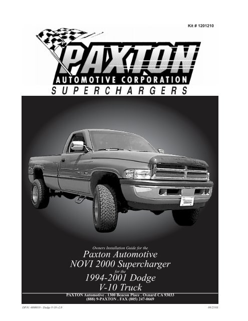
<strong>Paxton</strong> Automotive<br />
NOVI 2000 Supercharger<br />
for the<br />
<strong>1994</strong>-<strong>2001</strong> <strong>Dodge</strong><br />
V-<strong>10</strong> <strong>Truck</strong><br />
PAXTON Automotive . 1300 Beacon Place . Oxnard CA 93033<br />
(888) 9-PAXTON . FAX (805) 247-0669<br />
DP/N: 4800019 - <strong>Dodge</strong> V-<strong>10</strong> v2.0 09/25/03
This manual provides information on the installation, maintenance and servicing of the <strong>Paxton</strong><br />
NOVI-2000 Supercharger kit expressly designed for the <strong>1994</strong>-<strong>2001</strong> <strong>Dodge</strong> V-<strong>10</strong> truck. Contact<br />
<strong>Paxton</strong> for information regarding these modifications at (805)604-1336 7:00 a.m.-3:30p.m.<br />
PST.<br />
An understanding of the information contained herein will help novices as well as experienced technicians<br />
to correctly install and receive the greatest possible benefit from their <strong>Paxton</strong> Supercharger.<br />
When reference is made in this manual to a brand name, number or specific tool or technique, an<br />
equivalent product may be used in place of the item mentioned. All information, illustrations and<br />
specifications contained herein are based on the latest product information available at the time of the<br />
publication. The right is reserved to make changes at any time without notice.<br />
KIT P/N: 12012<strong>10</strong><br />
© 2003 PAXTON AUTOMOTIVE<br />
All rights recerved. No parts of this publication may be reproduced, transmitted, transcrived, or translated into<br />
another language in any form, by any means without written permission of <strong>Paxton</strong> Automotive.<br />
P/N: 4800019<br />
©2003 <strong>Paxton</strong> Automotive<br />
All Rights Reserved, Intl. Copr. Secured<br />
25SEP03 v2.0 <strong>Dodge</strong> V-<strong>10</strong>(4800019v2.0)<br />
ii
TABLE OF CONTENTS<br />
FOREWORD . . . . . . . . . . . . . . . . . . . . . . . . . . . . . . . . . . . . . . . . . . . . . . . . . . . . . . . . .2<br />
TABLE OF CONTENTS . . . . . . . . . . . . . . . . . . . . . . . . . . . . . . . . . . . . . . . . . . . . . . . . .TC-I<br />
1.0 INTRODUCTION . . . . . . . . . . . . . . . . . . . . . . . . . . . . . . . . . . . . . . . . . . . . . . . .1-1<br />
2.0 INITIAL PREPARATION AND DISASSEMBLY . . . . . . . . . . . . . . . . . . . . . . . .2-1<br />
3.0 SUPERCHARGER INSTALLATION AND ASSEMBLY . . . . . . . . . . . . . . . . . .3-1<br />
4.0 ADDITIONAL INJECTOR CONTROLLER INSTALLATION. . . . . . . . . . . . . . .4-1<br />
5.0 FINAL CHECK AND START-UP . . . . . . . . . . . . . . . . . . . . . . . . . . . . . . . . . . . . .5-1<br />
APPENDICES<br />
Appendix A<br />
Appendix B<br />
Appendix C<br />
Appendix D<br />
Appendix E<br />
Appendix F<br />
Appendix G<br />
Appendix H<br />
Appendix I<br />
Appendix J<br />
Appendix K<br />
Appendix L<br />
Appendix M<br />
Appendix N<br />
PARTS LIST . . . . . . . . . . . . . . . . . . . . . . . . . . . . . . . . . . . . . . . . . . . . .A-2<br />
ASY, NOVI 2000 SUPERCHARGER . . . . . . . . . . . . . . . . . . . . . . . . . .A-3<br />
ASY, SUPERCHARGER MOUNTING BRACKET . . . . . . . . . . . . . . .A-4<br />
ASY, CRANK PULLEY . . . . . . . . . . . . . . . . . . . . . . . . . . . . . . . . . . . .A-5<br />
ASY, AIR INTAKE . . . . . . . . . . . . . . . . . . . . . . . . . . . . . . . . . . . . . . . .A-6<br />
ASY, AIR DISCHARGE . . . . . . . . . . . . . . . . . . . . . . . . . . . . . . . . . . . .A-7<br />
ASY, COMPRESSOR BYPASS . . . . . . . . . . . . . . . . . . . . . . . . . . . . . . .A-8<br />
ASY, SPRING LOADED TENSIONER . . . . . . . . . . . . . . . . . . . . . . . .A-9<br />
ASY, AUXILIARY FUEL SYSTEM . . . . . . . . . . . . . . . . . . . . . . . . . . .A-<strong>10</strong><br />
ASY, FUEL ENRICHMENT . . . . . . . . . . . . . . . . . . . . . . . . . . . . . . . . .A-11<br />
ASY, OIL SUPPLY AND RETURN . . . . . . . . . . . . . . . . . . . . . . . . . . . .A-12<br />
ASY, HEATER HOSE RELOCATION . . . . . . . . . . . . . . . . . . . . . . . . .A-13<br />
RADIATOR HOSE EXTENSION ASSEMBLY . . . . . . . . . . . . . . . . . . .A-14<br />
ASY, WASHER BOTTLE RELOCATION . . . . . . . . . . . . . . . . . . . . . . .A-15<br />
iii<br />
P/N: 4800019<br />
©2003 <strong>Paxton</strong> Automotive<br />
All Rights Reserved, Intl. Copr. Secured<br />
25SEP03 v2.0 <strong>Dodge</strong> V-<strong>10</strong>(4800019v2.0)
This Page Left Intentionally Blank<br />
P/N: 4800019<br />
©2003 <strong>Paxton</strong> Automotive<br />
All Rights Reserved, Intl. Copr. Secured<br />
25SEP03 v2.0 <strong>Dodge</strong> V-<strong>10</strong>(4800019v2.0)<br />
iv
Section 1.0<br />
INTRODUCTION<br />
Congratulations! You have purchased the<br />
finest street supercharger available for the<br />
<strong>1994</strong>-<strong>2001</strong> <strong>Dodge</strong> V-<strong>10</strong> truck. The centerpiece<br />
of the kit is the highly efficient and reliable<br />
PAXTON NOVI-2000 supercharger - a<br />
mechanically driven (by belt) centrifugal blower<br />
(supercharger).<br />
This kit comes with all of the parts you’ll need<br />
for a successful installation. The operations<br />
required have been grouped in order of<br />
sequence. Photos and drawings accompany the<br />
text, allowing quick orientation and parts identification.<br />
Installation requires a selection of tools which<br />
are listed in a table at the end of this section.<br />
We also suggest that you obtain a <strong>Dodge</strong> truck<br />
shop manual and become familiar with the<br />
details of your car’s systems. Manuals may be<br />
obtained from your local <strong>Dodge</strong> dealer or you<br />
can order one from Helm Publications at (800)<br />
782-4356.<br />
For best results, follow the instructions closely<br />
and in sequence. The average installation time<br />
for this kit is 8-<strong>10</strong> hours. Your actual installation<br />
time will depend on skill level and working conditions.<br />
The estimate does not include time for<br />
initial vehicle inspection, cleaning, fine tuning<br />
or troubleshooting. Before even picking up a<br />
wrench, read this entire manual. We are available<br />
for technical assistance at (805) 604-<br />
1336, 7 AM-3:30 PM Pacific Time.<br />
After reading the manual, verify that all major<br />
assembly groups are present in the main kit box.<br />
You should have ample space to lay out the<br />
components. As you remove a box or bag from<br />
the main kit, note the identification label and<br />
compare it with the parts list. Please check the<br />
box for small parts.<br />
<strong>Paxton</strong> makes every effort to insure that all parts<br />
are included in the box. However, if you discover<br />
any missing or mislabeled parts, please contact<br />
<strong>Paxton</strong> by phone for service.<br />
***** WARNING *****<br />
DO NOT attempt installation if any part(s)<br />
are missing from this kit. Failure to contact<br />
<strong>Paxton</strong> prior to beginning installation will<br />
result in a charge for any missing parts.<br />
Before starting the installation, we suggest your<br />
engine and engine compartment be clean. You<br />
can clean the engine and compartment with a<br />
pressure washer (such as those used at self-serve<br />
car washes) and a safe-for-aluminum<br />
cleaner/degreaser. Cover the distributor with a<br />
plastic bag to prevent water from entering.<br />
***** CAUTION *****<br />
We do not recommend proceeding with<br />
the kit installation unless your vehicle is<br />
within normal operating parameters.<br />
You are undoubtedly enthusiastic about getting<br />
started on your project, but take just a little more<br />
time to insure that your safety is not jeopardized.<br />
A moment’s lack of attention can result in<br />
an accident, as can failure to observe certain<br />
simple safety precautions. The possibility of an<br />
accident will always exist, and the following<br />
points should not be considered a comprehensive<br />
list of all dangers. Rather, they are intended<br />
to make you aware of the risks and to encourage<br />
a safety conscious approach to all work you do<br />
on your vehicle.<br />
• Never rely solely on a jack when working<br />
under a vehicle. Always use approved jackstands<br />
to support the vehicle and place them<br />
under the recommended lift points.<br />
• When jacking the vehicle, make sure it is on<br />
a level surface, preferably concrete or<br />
asphalt. The transmission should be in<br />
1-1<br />
P/N: 4800019<br />
©2003 <strong>Paxton</strong> Automotive<br />
All Rights Reserved, Intl. Copr. Secured<br />
25SEP03 v2.0 <strong>Dodge</strong> V-<strong>10</strong>(4800019v2.0)
“PARK” or “FIRST”, the parking brake<br />
engaged, and the wheels blocked.<br />
• Never start the car without first verifying<br />
that the transmission is in neutral and the<br />
parking brake is set.<br />
• Never remove the radiator cap while the<br />
engine is still hot.<br />
• Always wear eye protection when using<br />
power tools such as drills, saws, grinders,<br />
etc., or when working under a vehicle.<br />
• Never smoke, use an open flame, or have<br />
spark-producing items around gasoline or<br />
flammable solvents. Always have a fire<br />
extinguisher rated for chemical and electrical<br />
fires handy when working on motor vehicles.<br />
• Run engines only in a well ventilated area.<br />
Carbon monoxide, gasoline and solvent<br />
vapors are colorless, and sometimes odorless.<br />
These can asphyxiate or explode without<br />
warning.<br />
• Always disconnect at least the (-) negative or<br />
ground terminal of the battery when doing<br />
any electrical, fuel system, or under-dash<br />
work.<br />
We look forward to hearing from you, particularly<br />
if you have any comments or suggestions<br />
regarding this manual.<br />
NOTE:<br />
Throughout these procedures the word<br />
“discard” is used periodically in relationship<br />
to items that will no longer be utilized in<br />
conjunction with the supercharger installation.<br />
It is recommended that these items<br />
be saved for future use should it become<br />
necessary.<br />
RECOMMENDED<br />
TOOLS FOR<br />
INSTALLATION:<br />
9/16” Wrench<br />
3/8” Ratchet<br />
9/16” Socket 3/8” Drive<br />
5/8” Socket 3/8” Drive<br />
Pliers<br />
Hacksaw<br />
Wire Cutters<br />
13mm Socket 3/8” Drive<br />
<strong>10</strong>mm Socket<br />
Long Extension<br />
Wire Crimper/Strippers<br />
13mm Wrench<br />
Medium Extension<br />
Drill Motor<br />
1/8” Drill Bit<br />
13/64” Drill Bit”<br />
1/4” Drill Bit<br />
5/16” Nut Driver or Slot Screwdriver<br />
1/4” Allen Wrench or Socket<br />
3/4” Socket<br />
8mm Wrench<br />
Hose Cutter or Sharp Knife<br />
#2 Phillips Screwdriver<br />
13mm Socket 3/8” Drive<br />
Air Chisel/Hammer<br />
Harmonic Balancer Puller<br />
Power Steering Pulley/Puller Installer<br />
P/N: 4800019<br />
©2003 <strong>Paxton</strong> Automotive<br />
All Rights Reserved, Intl. Copr. Secured<br />
25SEP03 v2.0 <strong>Dodge</strong> V-<strong>10</strong>(4800019v2.0)<br />
1-2
Section 2.0<br />
INITIAL PREPARATION AND DISASSEMBLY<br />
In this section, you will be preparing for the<br />
installation procedure by disconnecting the<br />
battery cables and removing and relocating<br />
a few pieces to make room for your new<br />
<strong>Paxton</strong> supercharger.<br />
2.1 INITIAL DISASSEMBLY AND<br />
REMOVAL:<br />
A. With a 1/2” wrench, remove both battery<br />
cables.<br />
B. An 8mm wrench or socket is used to<br />
remove the battery hold-down. Lift the<br />
battery out of the tray and set it aside.<br />
C. Unclip the cruise control cable from the<br />
throttle body and mount if equipped.<br />
(See Fig. 2-a.)<br />
Fig 2-b<br />
E. Use a <strong>10</strong>mm wrench and remove the<br />
cruise control actuator from the bottom<br />
of the battery tray. Later it will be modified<br />
and reinstalled. (See Fig. 2-c.).<br />
*** NOTE ***<br />
On some later model trucks, the factory relocated<br />
the cruise control actuator so this step will not need<br />
to be done.<br />
Fig 2-a<br />
D. The tray is secured with two bolts and<br />
two nuts above and two more accessible<br />
from below. Use a 13mm socket with an<br />
extension, and raise the battery tray<br />
from the vehicle. (See Fig. 2-b.)<br />
Fig 2-c<br />
2-1<br />
P/N: 4800019<br />
©2003 <strong>Paxton</strong> Automotive<br />
All Rights Reserved, Intl. Copr. Secured<br />
25SEP03 v2.0 <strong>Dodge</strong> V-<strong>10</strong>(4800019v2.0)
2.2 AIR INTAKE ASSEMBLY:<br />
A. Disconnect the plastic duct from<br />
between the air cleaner assembly and<br />
the air horn on the radiator core support<br />
(See Fig. 2-d.).<br />
C. Unclip the air cleaner assembly from its<br />
base and remove it along with the air filter<br />
element. (See Fig. 2-f.)<br />
Fig 2-f<br />
D. Use a 7/16” deep socket and remove<br />
the four nuts securing the air cleaner<br />
base to the throttle body.<br />
E. Pull the base away from the throttle<br />
body and disconnect the crankcase vent<br />
hose from it. Set it aside, it will not be<br />
reused. (See Fig. 2-g.)<br />
Fig 2-d<br />
B. There are two bolts securing the air horn<br />
to the core support. From the front of<br />
the core support, use a <strong>10</strong>mm socket and<br />
remove the horn from the core support.<br />
You will have to bend the bracket in<br />
order to remove it. (See Fig. 2-e.)<br />
Fig 2-g<br />
2.3 FAN AND FAN SHROUD:<br />
***WARNING***<br />
Clean up any anti-freeze spillage immediately.<br />
Animals like the taste of coolant, and if ingested<br />
they can become very sick, and even die.<br />
A. With a pair of pliers, remove the lower<br />
radiator hose and drain the coolant from<br />
the vehicle. Replace the hose and resecure<br />
with the factory clamp.<br />
Fig 2-e<br />
P/N: 4800019<br />
©2003 <strong>Paxton</strong> Automotive<br />
All Rights Reserved, Intl. Copr. Secured<br />
25SEP03 v2.0 <strong>Dodge</strong> V-<strong>10</strong>(4800019v2.0)<br />
2-2
B. Disconnect the upper radiator hose and<br />
fold it back out of the way.<br />
C. Unclip the window washer bottle from<br />
the shroud. Lift the bottle and disconnect<br />
the two plugs and the hose from the<br />
bottle. Set it aside. (See Fig. 2-h.)<br />
E. Remove the four screws securing the<br />
shroud to the radiator using a <strong>10</strong>mm<br />
socket. Lift the shroud and fan out of the<br />
engine compartment together. (See Fig.<br />
2-j.).<br />
Fig 2-h<br />
D. With a 36mm wrench or large crescent<br />
wrench, loosen the fan and remove it<br />
from the water pump. Set it into the fan<br />
shroud.<br />
*** NOTE ***<br />
This nut has right hand threads. (See Fig. 2-i.)<br />
Fig 2-j<br />
2.4 POWER STEERING BRACKET:<br />
A. Use a 16mm wrench, turn the belt tensioner<br />
counter clockwise and remove the<br />
stock accessory drive belt. (See Fig.<br />
2-k.)<br />
Fig 2-k<br />
Fig 2-i<br />
2-3<br />
P/N: 4800019<br />
©2003 <strong>Paxton</strong> Automotive<br />
All Rights Reserved, Intl. Copr. Secured<br />
25SEP03 v2.0 <strong>Dodge</strong> V-<strong>10</strong>(4800019v2.0)
B. Follow the accompanying instructions<br />
with the power steering pulley<br />
puller/pusher and remove the power<br />
steering pulley. (See Fig. 2-l.)<br />
D. With a 9/16” socket and extension,<br />
remove the four bolts that secure the<br />
power steering bracket to the engine. Do<br />
not disconnect the fluid lines.<br />
E. On the back of the pump, remove the<br />
two nuts with a 15mm wrench and the<br />
two bolts with a 12mm socket. Remove<br />
the bracket from the pump and lay the<br />
pump on the steering box. Grab the<br />
power steering pump with both hands.<br />
Bend the pressure line down until it is<br />
flat, as shown. (See Fig. 2-n.)<br />
FLATTEN OUT<br />
BEND IN<br />
METAL LINE<br />
DODGE V-<strong>10</strong><br />
POWER STEERING<br />
PUMP HOSE<br />
MODIFICATION<br />
P/S/PUMP<br />
REAR VIEW<br />
BEND DOWN<br />
Fig 2-l<br />
C. Use a 15mm socket and remove the<br />
three bolts securing the pump to the<br />
bracket. (See Fig. 2-m.)<br />
METAL LINE<br />
SHOULD<br />
LOOK LIKE<br />
THIS AFTER<br />
BENDING.<br />
CAP<br />
TOP VIEW<br />
Fig 2-n<br />
F. Remove the bolt from the upper rod on<br />
the A/C compressor with a 1/2” socket.<br />
(See Fig. 2-o.)<br />
Fig 2-m<br />
Fig 2-o<br />
P/N: 4800019<br />
©2003 <strong>Paxton</strong> Automotive<br />
All Rights Reserved, Intl. Copr. Secured<br />
25SEP03 v2.0 <strong>Dodge</strong> V-<strong>10</strong>(4800019v2.0)<br />
2-4
G. With a 9/16” socket, remove the four<br />
bolts securing the A/C bracket to the<br />
head. (See Fig 2-p.)<br />
Fig 2-r<br />
I. Lift the A/C bracket up and out of the<br />
way. Remove the long heater hose nipple<br />
from the water pump with a 3/4”<br />
wrench. (See Fig. 2-s.)<br />
Fig 2-p<br />
H. With a pair of pliers, disconnect the<br />
heater hose at the splice. Then, remove<br />
the hose at the nipple on the side of the<br />
water pump. (See Figs 2-q, 2-r.)<br />
Fig 2-s<br />
Fig 2-q<br />
2-5<br />
P/N: 4800019<br />
©2003 <strong>Paxton</strong> Automotive<br />
All Rights Reserved, Intl. Copr. Secured<br />
25SEP03 v2.0 <strong>Dodge</strong> V-<strong>10</strong>(4800019v2.0)
J. Install the 45º brass elbow into the water<br />
pump and tighten with a 13/16” wrench.<br />
Use Teflon tape and position as shown.<br />
(See Fig. 2-t.)<br />
L. Reinstall the A/C bracket using the stock<br />
bolts. When resecuring the rod to the top<br />
of the compressor, secure the two<br />
ground wires previously secured to the<br />
power steering pump bracket. Install the<br />
wires between the rod and the compressor.<br />
(See Fig. 2-v.)<br />
Fig 2-t<br />
K. Install the brass nipple into the fitting<br />
installed in step 2-t with Teflon tape and<br />
tighten with a 5/8” wrench. (See Fig.<br />
2-u and Appendix M.)<br />
Fig 2-v<br />
Fig 2-u<br />
P/N: 4800019<br />
©2003 <strong>Paxton</strong> Automotive<br />
All Rights Reserved, Intl. Copr. Secured<br />
25SEP03 v2.0 <strong>Dodge</strong> V-<strong>10</strong>(4800019v2.0)<br />
2-6
Section 3.0<br />
SUPERCHARGER INSTALLATION AND ASSEMBLY<br />
Now we start modifying various electrical<br />
and mechanical assemblies as well as<br />
beginning the supercharger installation.<br />
B. Secure the cruise control to the two<br />
screws that secure the windshield wiper<br />
motor, near the firewall and the washer<br />
bottle. (See Fig 3-c.)<br />
***NOTE***<br />
On some later model vehicles, this step will not<br />
apply.<br />
3.1 MODIFICATION AND INSTALLA-<br />
TION<br />
A. Modify the previously removed Cruise<br />
Control bracket as shown.(See Figs. 3-a,<br />
3-b.) It is not necessary to remove the<br />
Cruise Control Actuator from the bracket.<br />
Fig 3-a<br />
LENGTHEN THIS HOLE<br />
Fig 3-c<br />
C. Use the supplied wire, wire loom and<br />
butt connectors to extend the factory<br />
harness to the cruise control module.<br />
Cut off the plug leaving about 6” of<br />
wire.<br />
3.2 WINDOW WASHER BOTTLE<br />
A. The washer bottle will be mounted on<br />
the passenger side firewall. The wire<br />
bracket must be bent in order for the<br />
bottle to clear the A/C line running<br />
across the firewall in that area. Bend an<br />
offset in the bracket, set it in place and<br />
mark the mounting holes. Use a 1/8”<br />
drill and drill the two mounting holes.<br />
(See Fig. 3-d.)<br />
CUT LINE<br />
.2<br />
ORIGINAL PART<br />
MODIFIED BRACKET<br />
Fig 3-b<br />
3-1<br />
P/N: 4800019<br />
©2003 <strong>Paxton</strong> Automotive<br />
All Rights Reserved, Intl. Copr. Secured<br />
25SEP03 v2.0 <strong>Dodge</strong> V-<strong>10</strong>(4800019v2.0)
Fig 3-d<br />
B. Remove the pump and sensor from the<br />
factory washer bottle along with their<br />
grommets. Use a small amount of clear<br />
silicone and install the grommets in the<br />
new bottle so that the pump is positioned<br />
on the inboard side and the sensor<br />
is toward the passenger fender. Push<br />
the pump and sensor into their respective<br />
holes.<br />
C. Set the bottle in place and secure it to<br />
the firewall with the supplied sheet<br />
metal screws.<br />
*** NOTE ***<br />
To save a step, it is recommended at this time, to<br />
tap into the factory wiring harness for the additional<br />
injector driver. Refer to Appendix L for ECU pin location.<br />
D. Near the brake master cylinder, separate<br />
the washer hose at the splice. Connect<br />
the supplied length of washer hose to<br />
the piece running to the wipers and<br />
route the other end to the pump.<br />
E. In the battery tray area, cut the electrical<br />
connectors for the pump and sensor off<br />
of the harness, leave at least 6” of length<br />
left with the connectors.<br />
F. Use the supplied lengths of wire, plastic<br />
loom and butt connectors to extend the<br />
harness back to the pump and sensor.<br />
(Appendix ‘P’)<br />
G. Route the harness extension back and<br />
along the firewall. Use the supplied<br />
plastic ties to secure it away from any<br />
hot or moving parts. (See Fig. 3-e.)<br />
Fig 3-e<br />
3.3 CRANK PULLEY:<br />
A. Using a 1-1/8” socket remove the large<br />
center bolt from the crank pulley.<br />
B. With an adequate puller, pull the crank<br />
pulley off of the crank shaft. (See Fig.<br />
3-f.)<br />
P/N: 4800019<br />
©2003 <strong>Paxton</strong> Automotive<br />
All Rights Reserved, Intl. Copr. Secured<br />
25SEP03 v2.0 <strong>Dodge</strong> V-<strong>10</strong>(4800019v2.0)<br />
3-2
E. Use a 9/16" socket and install the crank<br />
pulley on the adapter with the four 3/8"<br />
bolts. (See Fig. 3-h.)<br />
Fig 3-h<br />
Fig 3-f<br />
C. Replace the stock crank pulley with the<br />
supplied re-machined pulley. Pull the<br />
pulley onto the crank shaft with the<br />
stock large center bolt.<br />
D. Remove the center bolt and place the<br />
new center hub into the middle of the<br />
crank pulley. Align the two dowel pins<br />
and secure with the longer supplied center<br />
bolt. Reuse the large washer from the<br />
factory center bolt. Torque the bolt to<br />
150ft-lbs. (See Fig. 3-g, Appendix ‘D’)<br />
Fig 3-g<br />
3-3<br />
P/N: 4800019<br />
©2003 <strong>Paxton</strong> Automotive<br />
All Rights Reserved, Intl. Copr. Secured<br />
25SEP03 v2.0 <strong>Dodge</strong> V-<strong>10</strong>(4800019v2.0)
F. Remove the current spark plugs and<br />
replace with copper plugs (AutoLite<br />
#5224 or equivalent) gapped at .035. Do<br />
not use platinum spark plugs with the<br />
supercharger.<br />
3.4 SUPERCHARGER BRACKET:<br />
A. Install the backing plate to the front of<br />
the engine with one 3/8" x 1" bolt and a<br />
second 3/8" bolt as an alignment bolt as<br />
shown. Torque the first bolt to 28-30<br />
ft/lbs. Remove the alignment bolt (See<br />
Fig. 3-i.)<br />
B. Mount the power steering pump to the<br />
front plate using two of the stock bolts<br />
and two of the supplied countersunk<br />
bolts. (See Fig. 3-j.)<br />
Fig 3-j<br />
Fig 3-i<br />
P/N: 4800019<br />
©2003 <strong>Paxton</strong> Automotive<br />
All Rights Reserved, Intl. Copr. Secured<br />
25SEP03 v2.0 <strong>Dodge</strong> V-<strong>10</strong>(4800019v2.0)<br />
3-4
C. Nine bolts secure the front plate to the<br />
rear plate. The longest bolt enters the<br />
lowest part of the bracket. The next<br />
three shorter bolts enter the bracket<br />
above and thread into the head. The next<br />
four enter the bracket to the side of the<br />
engine and thread into the rear plate.<br />
The last, shortest bolt enters the bracket<br />
through the counter-bored hole. Start all<br />
nine bolts before tightening them to 28-<br />
30ft-lbs. (See Fig. 3-k, Appendix ‘C’.)<br />
D. Follow the supplied instructions and use<br />
the pulley pusher to re-install the power<br />
steering pulley. Use a small amount of<br />
anti-seize lubricant to ease installation.<br />
(See Fig. 3-l.)<br />
Fig 3-l<br />
F. Cut off about 2” of heater hose where<br />
you disconnected it at the splice.<br />
G. Use the supplied section of hose and<br />
clamps to install the supplied heater tube<br />
as shown. (See Fig. 3-m, Appendix ‘M’.)<br />
Fig 3-k<br />
Fig 3-m<br />
3-5<br />
P/N: 4800019<br />
©2003 <strong>Paxton</strong> Automotive<br />
All Rights Reserved, Intl. Copr. Secured<br />
25SEP03 v2.0 <strong>Dodge</strong> V-<strong>10</strong>(4800019v2.0)
3.5 SUPERCHARGER INSTALLATION:<br />
A. Drain the oil from the engine. Save and<br />
reuse or dispose of properly.<br />
B. Follow the diagram and with the supplied<br />
punch, knock a hole in the side of<br />
the oil pan (see Fig. 3-n). Carefully<br />
drive the punch a small way into the<br />
pan, then check the hole size with the<br />
tap. Do this until the hole is the correct<br />
size for the tap. .The hole should be<br />
approximately Ø9/16".<br />
E. Make sure that the power steering hose<br />
is up as high as possible against the<br />
bracket. (See Fig. 3-p.)<br />
DODGE V-<strong>10</strong> OIL PAN DRAIN LOCATION<br />
7-1/2"<br />
1-1/4"<br />
INSTALL FITTING POINTING FORWARD AND UP 5° FROM LEVEL<br />
5°<br />
Fig 3-n<br />
C. Coat a 3/8” pipe tap with grease and tap<br />
the hole. The grease will trap and hold<br />
the shavings. Using silicone, install the<br />
supplied 90° fitting in the side of the<br />
pan. Angle the fitting forward and<br />
slightly upward.<br />
D. Place but do not attach the supplied oil<br />
drain hose through the middle of the<br />
bracket as shown. (See Fig. 3-o.)<br />
Fig 3-p<br />
F. Set the supercharger into the bracket and<br />
secure the oil drain hose to the fitting on<br />
the bottom of the supercharger with the<br />
supplied hose clamp. (See Fig. 3-q,<br />
Appendix ‘K’.)<br />
*** NOTE ***<br />
Make sure there are no dips or kinks in the oil drain<br />
line as this may effect supercharger life and reliability.<br />
Fig 3-q<br />
Fig 3-o<br />
P/N: 4800019<br />
©2003 <strong>Paxton</strong> Automotive<br />
All Rights Reserved, Intl. Copr. Secured<br />
25SEP03 v2.0 <strong>Dodge</strong> V-<strong>10</strong>(4800019v2.0)<br />
3-6
G. Set the unit down into the bracket and<br />
secure it to the bracket with the 5 supplied<br />
3/8-16 x 1.5” bolts, leave the third<br />
hole from the top open. (See Fig.3-r,<br />
Appendix ‘E’.)<br />
J. Mount the supplied belt tensioner to<br />
the mount with the large bolt, nut and<br />
washer through the middle of the tensioner.<br />
(See Fig. 3-t.)<br />
Fig 3-r<br />
H. From underneath the vehicle, secure the<br />
other end of the oil drain hose to the fitting<br />
on the oil pan with the supplied<br />
hose clamp.<br />
I. Install the supercharger belt tensioner<br />
mount to the front of the supercharger<br />
and the last open mounting hole in the<br />
front of the bracket, using supplied spacer.<br />
(See Fig. 3-s, Appendix ‘F’.)<br />
Fig 3-t<br />
K. On the passenger side of the engine,<br />
remove the factory oil pressure sensor<br />
located above the oil filter. Replace the<br />
sensor with the supplied street ‘TEE’.<br />
Position the ‘TEE’ so that the sensor<br />
will reinstall into the ‘TEE’ at an angle<br />
pointing toward the smog pump. (See<br />
Fig. 3-u.)<br />
ANGLE SENDER TOWARD FRONT OF VEHICLE<br />
SO IT CLEARS STEEL LINES AND SMOG PUMP<br />
<strong>10</strong>° TO 12°<br />
OIL PRESSURE<br />
SENDER<br />
STREET<br />
“TEE” GOES<br />
IN HOLE<br />
FOR STOCK<br />
SENDER<br />
Fig 3-s<br />
1/8" PIPE<br />
TO -48°<br />
OIL<br />
FILTER<br />
DODGE V-<strong>10</strong> OIL PRESSURE<br />
SENDER/OIL FEED LINE<br />
SIDE<br />
VIEW<br />
Fig 3-u<br />
3-7<br />
P/N: 4800019<br />
©2003 <strong>Paxton</strong> Automotive<br />
All Rights Reserved, Intl. Copr. Secured<br />
25SEP03 v2.0 <strong>Dodge</strong> V-<strong>10</strong>(4800019v2.0)
L. Install the sensor and connect the supplied<br />
oil pressure hose to the last port on<br />
the TEE.<br />
M. Route the pressure line up and across<br />
the front of the engine behind the smog<br />
pump and alternator and over to the<br />
supercharger. Connect the line to the<br />
previously installed fitting leading to the<br />
oil jets in the supercharger. (See Fig.<br />
3-v.)<br />
3.6 FAN AND SHROUD MODIFICATION<br />
AND INSTALLATION<br />
A. Screw the new fan spacer on the front of<br />
the water pump, snug by hand. (See Fig.<br />
3-w.)<br />
Fig. 3-w<br />
B. With a saws-all or jig saw, cut the<br />
tapered area off of the bottom of the fan<br />
shroud to gain fan clearance. (See Figs.<br />
3-x, 3-y.)<br />
Fig. 3-x<br />
BOTTOM OF FAN SHROUD<br />
1-1/2"<br />
Fig 3-v<br />
N. You can now install the drive belts.<br />
Follow the factory routing and install<br />
the accessory drive belt as it was<br />
removed.<br />
O. Install the supercharger drive belt using<br />
the supplied tensioning tool.<br />
REMOVE SHADED AREA<br />
Fig 3-y<br />
C. Place the fan into the shroud and drop<br />
them both into the engine compartment<br />
together. Screw the fan with the new fan<br />
spacer and tighten with the 36mm<br />
wrench. This will tighten the spacer as<br />
well.<br />
D. Secure the fan shroud with the factory<br />
bolts.<br />
P/N: 4800019<br />
©2003 <strong>Paxton</strong> Automotive<br />
All Rights Reserved, Intl. Copr. Secured<br />
25SEP03 v2.0 <strong>Dodge</strong> V-<strong>10</strong>(4800019v2.0)<br />
3-8
3.7 AIR INTAKE ASSEMBLY<br />
A. With the clamps on the intake tube<br />
loose, slip the tube in behind the supercharger<br />
from above, it will go through<br />
the “loop” in the power steering hose.<br />
Secure the tube to the inlet in the center<br />
of the supercharger, rotate the tube so<br />
that it follows the contour of the inner<br />
fender and tighten the clamps. (See Fig.<br />
3-z, Appendix ‘E’.)<br />
C. With a <strong>10</strong>mm socket, remove the screw<br />
from the upper radiator mount. Secure<br />
the bracket on the top of the air filter to<br />
the radiator mount with the stock<br />
screw.(See Fig. 3-bb.)<br />
Fig. 3-bb<br />
Fig. 3-z<br />
B. On the air intake assemble, slip the supplied<br />
length of flex hose on the end of<br />
the intake tube about 2” and tighten the<br />
clamp. (See Fig. 3-aa.)<br />
D. Connect the rubber elbow on the air filter<br />
assembly to the flex hose. Route the<br />
1/2" vent hose under the flex hose and<br />
up to the rear of the valve cover.<br />
Connect the vent hose to the nipple in<br />
the valve cover and tighten the clamp.<br />
Connect the other end of the hose to the<br />
plastic elbow in the air filter. (See<br />
Appendix ‘E’.)<br />
Fig. 3-aa<br />
3-9<br />
P/N: 4800019<br />
©2003 <strong>Paxton</strong> Automotive<br />
All Rights Reserved, Intl. Copr. Secured<br />
25SEP03 v2.0 <strong>Dodge</strong> V-<strong>10</strong>(4800019v2.0)
3.8 AIR DISCHARGE ASSEMBLY<br />
A. Secure the throttle body adapter flange<br />
to the throttle body on the factory studs<br />
with the stock nuts and gasket. (See Fig.<br />
3-cc, Appendix ‘H’.)<br />
D. Route the supplied length of vacuum<br />
hose from the valve, across the engine<br />
and with the supplied TEE, connect it to<br />
the vacuum nipple on the front of the<br />
upper intake manifold. (See Fig. 3-ee.)<br />
Fig 3-cc<br />
B. Install the discharge tube between the<br />
adapter flange and the outlet of the<br />
supercharger. Adjust the turbo sleeves<br />
and tighten all the clamps. (See Fig.<br />
3-dd.)<br />
Fig 3-ee<br />
E. Route the fuel line from the discharge<br />
tube fuel rail to the passenger side fuel<br />
rail, being careful to avoid any potentially<br />
hot surfaces.<br />
F. Fuel system is under pressure. Relieve<br />
pressure by depressing on the Schraeder<br />
Valve Core, using a small pen or screwdriver.<br />
G. Remove the Schraeder Valve from the<br />
passenger side fuel rail and connect the<br />
fuel line from the discharge tube assembly<br />
to the fuel rail.<br />
Fig 3-dd<br />
C. Between the 1" nipples on the intake<br />
and discharge tubes, install the compressor<br />
bypass valve with the supplied sections<br />
of hose and clamps. The bottom of<br />
the diaphragm in the valve should be<br />
facing the discharge tube.<br />
P/N: 4800019<br />
©2003 <strong>Paxton</strong> Automotive<br />
All Rights Reserved, Intl. Copr. Secured<br />
25SEP03 v2.0 <strong>Dodge</strong> V-<strong>10</strong>(4800019v2.0)<br />
3-<strong>10</strong>
3.9 FUEL SYSTEM MODIFICATION<br />
A. Open the driver’s door, remove the plastic<br />
trim across the bottom of the door<br />
jam and lift the carpet.<br />
B. From under the vehicle, align the fuel<br />
system mounting plate (Assembly<br />
#<strong>10</strong>20<strong>10</strong>1) Appendix “I” to the underside<br />
of the floor pan so that the notched<br />
out section surrounds the parking brake<br />
cable. (See Fig. 3-ff.)<br />
***NOTE***<br />
On some later mocel vehicles, you may have to<br />
move the F/P mounting plate foreward for best fuel<br />
hose routing.<br />
f. Disconnect the factory fuel line from the<br />
fitting. Connect the Auxiliary Fuel system<br />
to the Factory Fuel line. (See Fig.<br />
3-gg.)<br />
V-<strong>10</strong> DODGE FUEL SYSTEM MOUNTING PLATE<br />
(Looking at underside of driver’s floor)<br />
EMERGENCY<br />
BRAKE CABLE<br />
DRILL MOUNTING<br />
HOLES THROUGH<br />
SHEET METAL LIP<br />
Fig 3-gg<br />
ROCKER PANEL<br />
CENTER<br />
E-BRAKE<br />
CABLE IN<br />
NOTCH<br />
DRILL<br />
THROUGH<br />
FLOOR 2x<br />
FRAME<br />
3.<strong>10</strong> BATTERY AND RADIATOR WRAP UP<br />
A. Re-install the factory battery tray in the<br />
stock location with the stock nuts and<br />
bolts.<br />
B. Install the battery with the factory holddown.<br />
Reconnect the cables<br />
C. Connect the new upper radiator hose<br />
extension to the end of the factory radiator<br />
hose and to the radiator. Secure with<br />
the supplied clamps. (See Fig. 3-hh.)<br />
D. Fill the radiator with the fluid drained in<br />
the beginning of the installation.<br />
FRONT OF VEHICLE<br />
Fig 3-ff<br />
c. Mark and drill the mounting holes with<br />
a 1/4" drill.<br />
d. Secure the auxiliary fuel system to the<br />
floor pan with the supplied hardware.<br />
Re-install the carpet and plastic trim in<br />
the door jam. (See Appendix ‘I’.)<br />
e. From underneath the vehicle, take the<br />
two fuel lines from the auxiliary fuel<br />
system and thread them above the frame<br />
rail toward the fuel line.<br />
Fig. 3-hh<br />
3-11<br />
P/N: 4800019<br />
©2003 <strong>Paxton</strong> Automotive<br />
All Rights Reserved, Intl. Copr. Secured<br />
25SEP03 v2.0 <strong>Dodge</strong> V-<strong>10</strong>(4800019v2.0)
3.11 AICU RELAY INSTALLATION<br />
INSTRUCTIONS<br />
A. Locate a suitable location in the passenger<br />
compartment on the driver’s side of<br />
the vehicle. Under the dash, attach the<br />
AICU and the RPM signal box using<br />
nylon wire ties.<br />
B. Attach both of the red power wires from<br />
the AICU and the RPM signal box to<br />
terminal #87 on the supplied relay using<br />
the connectors provided.<br />
C. Attach both the black ground wires of<br />
the AICU and the RPM signal box to the<br />
fuse box ground using the ring terminals<br />
provided<br />
D. Using the provided butt connectors, connect<br />
the yellow/black wires of the RPM<br />
signal box to the yellow/black wire on<br />
the AICU controller.<br />
E. Locate the black ECU plug on the factory<br />
ECU. Attach the gralyblack wire from<br />
the RPM signal box to pin #8 on the<br />
factory ECU. (Refer to Appendix Q.)<br />
(See Fig. 3-ii.)<br />
H. Using the vacuum hose and TEE’s provided,<br />
connect one end of the vacuum<br />
hose to the AICU and route the hose<br />
through the firewall and TEE into the<br />
vacuum/boost hose going to the bypass<br />
valve.<br />
I. Recheck all of the wire connections. We<br />
recommend that you solder all wire connections.<br />
If you do not have access to a<br />
soldering gun you can use the connectors<br />
that are provided.<br />
Fig. 3-jj<br />
L. Using the AICU relay as a template,<br />
drill a .138 diameter hole in the firewall<br />
(Fig 3-kk. shows the approximate location).<br />
Mount the supplied relay using the<br />
self-tapping screw provided.<br />
Fig 3-ii<br />
F. Route the RPM signal wire across the<br />
firewall and into the driver’s compartment<br />
and connect it to the grey/black on<br />
the RPM signal box using the connectors<br />
provided.<br />
G. Run the AICU injector plugs through the<br />
grommet that would normally be used<br />
for the clutch cable. Route the injector<br />
plugs to the supplemental injectors<br />
located in the discharge tube. Route the<br />
wires away from hot or sharp objects<br />
and secure with nylon wire ties.<br />
*** NOTE ***<br />
The wires and injectors are connected in no particular<br />
order<br />
Fig 3-kk<br />
M. There are two sets of wires leading from<br />
the relay. Take the longer set of two<br />
wires and route them down and along<br />
the bottom frame rail and to the auxiliary<br />
fuel system. Attach them to the fuel<br />
pump, red to positive and black to negative.<br />
(See Fig 3-ll.)<br />
P/N: 4800019<br />
©2003 <strong>Paxton</strong> Automotive<br />
All Rights Reserved, Intl. Copr. Secured<br />
25SEP03 v2.0 <strong>Dodge</strong> V-<strong>10</strong>(4800019v2.0)<br />
3-12
Trigger Wire<br />
Attachment<br />
Fig 3-ll<br />
N. The set of three wires will run to the<br />
fuse box. Route them along the frame<br />
and firewall to the fuse box. (See Fig<br />
3-mm.)<br />
Fig 3-nn<br />
P. Attach the ground and power wires from<br />
the relay to the Fuse Box, red to positive,<br />
black to negative. (See Fig. 3-oo.)<br />
Route the wires<br />
along this path<br />
Fig 3-oo<br />
Fig 3-mm<br />
O. Attach the trigger wire (from the relay)<br />
to the solid blue wire [switched 12v]<br />
(from the wiring harness directly in<br />
front of the fuse box terminals) with the<br />
provided quick connector. (See Fig.<br />
3-nn.)<br />
3-13<br />
P/N: 4800019<br />
©2003 <strong>Paxton</strong> Automotive<br />
All Rights Reserved, Intl. Copr. Secured<br />
25SEP03 v2.0 <strong>Dodge</strong> V-<strong>10</strong>(4800019v2.0)
Here is your finished engine. Please take the time to do a final checkout.<br />
Make sure all of the items are properly tightened, and that you<br />
have refilled your oil and coolant to proper levels. Finally, take care<br />
driving until you have learned the new feel of your vehicle. It has<br />
more power now, and will handle differently on the road.<br />
P/N: 4800019<br />
©2003 <strong>Paxton</strong> Automotive<br />
All Rights Reserved, Intl. Copr. Secured<br />
25SEP03 v2.0 <strong>Dodge</strong> V-<strong>10</strong>(4800019v2.0)<br />
3-14
Section 4<br />
FINAL CHECK-OUT AND START-UP<br />
This section covers pre-start checks and<br />
inspections, as well as initial start-up.<br />
Your vehicle is now a high performance<br />
truck. Be sure to use only premium high<br />
octane fuel from now on.<br />
4.1 INSPECT THE FOLLOWING:<br />
a. Wires, harnesses and electrical connections.<br />
Are all items properly dressed, connected<br />
and secured<br />
b. Hoses, lines and fittings. Are all items<br />
properly dressed, connected, and<br />
secured<br />
c. Fasteners, brackets, and clamps. Are all<br />
items properly installed and tightened<br />
d. Fluid levels. Are the radiator coolant and<br />
engine oil at their proper levels Are<br />
there any fluid leaks<br />
e. Belt(s). Is the serpentine drive belt (or<br />
accessory drive and supercharger drive<br />
belts, depending on requirement of your<br />
vehicle) properly installed, aligned and<br />
tensioned<br />
4.2 PERFORM THE FOLLOWING:<br />
a. Cycle the ignition key from “OFF” to<br />
“ON” position three (3) times at fifteen<br />
(15) second intervals. Afterwards, check<br />
the entire fuel system for any leaks.<br />
b. Start the car. Verify that the oil pressure<br />
is within the normal operating range.<br />
Listen closely. The engine should idle<br />
and sound the same as it did before you<br />
began the installation.<br />
c. Allow the engine to come up to normal<br />
operating temperature. Bleed the cooling<br />
system and top off as necessary.<br />
4.3 CHECK FOR THE FOLLOWING:<br />
a. FLUID LEAKS.<br />
b. FLUID LEVELS.<br />
c. BELT SLIPPAGE.<br />
d. THROTTLE RESPONSE.<br />
***CAUTION***<br />
See the supercharger service manual included in<br />
your kit for information on supercharger servicing<br />
and maintenance, belt tightening, troubleshooting,<br />
special tuning, and warranty information.<br />
Now that the work is done, it’s time to enjoy<br />
your labor of love. Take the car out on the road<br />
and let it flex its muscles, but remember, the<br />
response and performance will now be different<br />
from that to which you have been accustomed.<br />
Have fun!<br />
4-1<br />
P/N: 4800019<br />
©2003 <strong>Paxton</strong> Automotive<br />
All Rights Reserved, Intl. Copr. Secured<br />
25SEP03 v2.0 <strong>Dodge</strong> V-<strong>10</strong>(4800019v2.0)
This Page Left Intentionally Blank<br />
P/N: 4800019<br />
©2003 <strong>Paxton</strong> Automotive<br />
All Rights Reserved, Intl. Copr. Secured<br />
25SEP03 v2.0 <strong>Dodge</strong> V-<strong>10</strong>(4800019v2.0)<br />
4-2
Appendix<br />
5-1<br />
P/N: 4800019<br />
©2003 <strong>Paxton</strong> Automotive<br />
All Rights Reserved, Intl. Copr. Secured<br />
23SEP03 v1.0 <strong>Dodge</strong> V-<strong>10</strong>(4800019v1.0)
Please understand that PAXTON Automotive is constantly improving the performance<br />
and look of the NOVI 2000 supercharger. Parts in your kit may<br />
appear differently than what is pictured in this manual. This is due to photographs<br />
taken in pre-production, a change in material, or an improvement in<br />
performance.<br />
Rest assured that you have purchased to best quality kit that PAXTON<br />
Automotive manufactures at this time. The installation of the materials will<br />
remain the same.<br />
List of Appendices<br />
Appendix Number......DWG Number.....Rev...........DWG Title<br />
A 12012<strong>10</strong> G KIT, 1993-01 DODGE RAM V<strong>10</strong><br />
B <strong>10</strong>19520 C ASY, S/C NOVI 2000 REAR DISCHARGE<br />
C <strong>10</strong>19602 E ASY, S/C MOUNTING BRACKET<br />
D <strong>10</strong>19701 C ASY, CRANK PULLEY<br />
E <strong>10</strong>198<strong>10</strong> C ASY, AIR INTAKE<br />
F <strong>10</strong>19603 D ASY, SPRING LOADED TENSIONER<br />
G <strong>10</strong>15512 NC ASY, COMPRESSOR BYPASS VALVE<br />
H <strong>10</strong>199<strong>10</strong> E ASY, AIR DISCHARGE, FUEL ENRICHMENT<br />
I <strong>10</strong>20<strong>10</strong>1 G ASY, AUXILIARY FUEL SYSTEM<br />
J <strong>10</strong>16031 B ASY, FUEL ENRICHMENT<br />
K <strong>10</strong>19313 E ASY, S/C OIL SUPPLY HOSE<br />
L <strong>10</strong>19314 D ASY, S/C OIL RETURN HOSE<br />
M <strong>10</strong>20350 B ASY, HEATER HOSE RELOCATION<br />
N <strong>10</strong>20360 B ASY, RADIATOR HOSE EXTENSION<br />
O <strong>10</strong>20450 B ASY, CRUISE CONTROL RELOCATION<br />
P <strong>10</strong>20550 C ASY, WASHER BOTTLE RELOCATION<br />
P/N: 4800019<br />
©2003 <strong>Paxton</strong> Automotive<br />
All Rights Reserved, Intl. Copr. Secured<br />
25SEP03 v2.0 <strong>Dodge</strong> V-<strong>10</strong>(4800019v2.0)<br />
A-2
ALIGN WITH CLAMP<br />
TOUCHING GEARCASE<br />
D<br />
E<br />
17<br />
REV.<br />
16<br />
15<br />
2<br />
4 REQD 19<br />
18<br />
6<br />
31<br />
AS REQD<br />
28 27 26<br />
AS REQD<br />
30 29 23<br />
2<br />
31 2 4<br />
2<br />
S/C ROTATION<br />
4<br />
LONG HUB<br />
TOWARD S/C<br />
14<br />
12<br />
13<br />
11<br />
<strong>10</strong><br />
8<br />
9<br />
3<br />
1<br />
3<br />
2<br />
7<br />
25<br />
5<br />
21<br />
4<br />
7<br />
6 REQD<br />
3 REQD<br />
20<br />
32 3<br />
2<br />
2<br />
ITEM NO. QTY. PART NO. DESCRIPTION<br />
9<br />
<strong>10</strong><br />
11<br />
12<br />
13<br />
14<br />
15<br />
16<br />
17<br />
18<br />
19<br />
20<br />
21<br />
22<br />
23<br />
24<br />
25<br />
26<br />
27<br />
28<br />
29<br />
31<br />
32<br />
23<br />
1<br />
1<br />
2<br />
2<br />
1<br />
1<br />
2<br />
2<br />
1<br />
1<br />
1<br />
1<br />
1<br />
1<br />
1<br />
1<br />
1<br />
1<br />
4<br />
1<br />
3<br />
6<br />
0<br />
0<br />
0<br />
0<br />
0<br />
0<br />
0<br />
1<br />
1<br />
1<br />
1<br />
2<br />
3<br />
4<br />
5<br />
6<br />
7<br />
8<br />
2H238-000<br />
7P375-017<br />
7P375-016<br />
7J375-024<br />
7PP375-090<br />
7P375-<strong>10</strong>4<br />
008704<br />
7U<strong>10</strong>0-075<br />
2H017-125<br />
4PCG031-350<br />
2H040-021<br />
2H040-011<br />
008718<br />
7B375-1<strong>10</strong><br />
2H018-051<br />
008706<br />
008719<br />
2H<strong>10</strong>0-035<br />
7U<strong>10</strong>0-021<br />
2H017-021<br />
2H<strong>10</strong>0-045<br />
7A250-050<br />
2H060-030<br />
2H<strong>10</strong>0-003<br />
2H<strong>10</strong>0-005<br />
2H<strong>10</strong>0-0<strong>10</strong><br />
2H060-031<br />
2H060-040<br />
2H060-041<br />
2H021-211<br />
7F375-024<br />
2H060-030<br />
GEARCASE ASY, N2K, CW, SAT<br />
FTG, NIPPLE, 3/8NPT X 1/2 HOSE BARB<br />
FTG, PLUG, 3/8NPT WITH MAGNET<br />
WASHER, COPPER CRUSH<br />
OIL JET, LONG<br />
SCREW, SCHD, 3/8-16UNC-2A X 1.00<br />
CAP, SHIPPING, T2<br />
KEY, 1/8 SQ. X 1.25 LG.<br />
SPACER, PULLEY, .125 THK.<br />
PULLEY, S/C <strong>10</strong> GRV, 3.50<br />
RET, CUP BLWR, PULLEY<br />
PULLEY RETAINER S/C<br />
CAP, TAMPER PROOF<br />
SCREW, HXHD, 3/8-24UNF-2A X 1.00<br />
VOLUTE, MACH, CURV, N2K<br />
CAP, SHIPPING, 3"<br />
CAP, SHIPPING, 4"<br />
NAMEPLATE NOVI 2000<br />
DRIVE SCREW, #4 X .187, GR5<br />
WASHER, ANTI-ROTATION<br />
CLAMP, VOLUTE<br />
SCREW, SCHD, 1/4-20UNC-2A X .50<br />
MATING RING, .090 THK.<br />
SHIM, IMP, .003 THK.<br />
SHIM, IMP, .005 THK.<br />
SHIM, IMP, .0<strong>10</strong> THK.<br />
MATING RING, .099 THK.<br />
MATING RING, .<strong>10</strong>3 THK.<br />
MATING RING, .112 THK.<br />
IMPLR, BAL, NOVI 2K, CCW<br />
NUT, IMP 3/8 LH SL 6PT<br />
MATING RING, .090 THK<br />
NOTES: UNLESS OTHERWISE SPECIFIED<br />
1. ALL PARTS TO BE SUITABLY PROTECTED AT ALL TIMES TO PREVENT DAMAGE.<br />
2. SHIM IMPELLER TO .031 WORKING HEIGHT USING ITEMS 23, 24, 25, 26, 27, 28, AND 29(FLOOR STOCK) AS REQUIRED.<br />
3. TORQUE TO 36 FT-LBS.<br />
4. HEAT TO 200•F TO EASE ASSEMBLY.<br />
UNLESS OTHERWISE SPECIFIED<br />
DIMENSIONS ARE IN INCHES<br />
TOLERANCES ARE:<br />
MATERIAL<br />
FINISH<br />
DECIMALS:<br />
NONE<br />
.XX± .01<br />
.XXX±.005<br />
FRACTIONS: ±1/2•<br />
ANGLES: ±1/16<br />
SEE PARTS LIST<br />
DRAWN<br />
ENGINEERING<br />
R&D<br />
APPR.<br />
CAD GENERATED DRAWING,<br />
DO NOT MANUALLY UPDATE<br />
APPROVALS<br />
JFC<br />
DATE<br />
<strong>10</strong>/3/97<br />
-----<br />
-----<br />
----- -----<br />
-----<br />
-----<br />
WEIGHT 21.8 LBS SCALE: 3:4<br />
SIZE DWG. NO.<br />
D<br />
1300 BEACON PLACE OXNARD, CA 93033<br />
TEL: (805) 604-1336 FAX: (805) 604-1337<br />
93-01 DODGE V-<strong>10</strong><br />
ASY, S/C NOVI 2000<br />
FORWARD ROTATION, 93-01 V-<strong>10</strong>, SATIN<br />
<strong>10</strong>19520<br />
DO NOT SCALE DRAWING<br />
REV.<br />
E<br />
SHEET 1 OF 1<br />
Appendix B <strong>10</strong>19520 Asy, S/C Novi 2000 Rear Discharge<br />
A-3<br />
P/N: 4800019<br />
©2003 <strong>Paxton</strong> Automotive<br />
All Rights Reserved, Intl. Copr. Secured<br />
23SEP03 v1.0 <strong>Dodge</strong> V-<strong>10</strong>(4800019v1.0)
*<br />
2<br />
*<br />
*<br />
* TO ENGINE BLOCK<br />
*<br />
6<br />
*<br />
16 <strong>10</strong><br />
16<br />
9<br />
16<br />
11<br />
16 11<br />
TO P/S PUMP<br />
19 17<br />
TO P/S PUMP<br />
18<br />
16 12<br />
4<br />
D 20<br />
5<br />
D<br />
1<br />
14 16<br />
7 8x<br />
SCREW PROVIDED W/<br />
TENSIONER ASY<br />
3 D 11 16<br />
13 16 5x<br />
(TO S/C)<br />
15<br />
8<br />
19<br />
HELD W/<br />
STOCK SCREW<br />
ON P/S PUMP<br />
D<br />
D<br />
D<br />
ITEM<br />
<strong>10</strong><br />
13<br />
12<br />
13<br />
14<br />
15<br />
16<br />
17<br />
18<br />
19<br />
20<br />
1<br />
2<br />
3<br />
4<br />
5<br />
6<br />
7<br />
8<br />
9<br />
QTY<br />
15<br />
1<br />
1<br />
1<br />
1<br />
1<br />
1<br />
1<br />
8<br />
1<br />
1<br />
3<br />
4<br />
1<br />
5<br />
1<br />
1<br />
1<br />
2<br />
1<br />
PART NUMBER<br />
3845417<br />
4PCG0<strong>10</strong>-045<br />
4PCG017-061<br />
12<strong>10</strong>5<strong>10</strong><br />
7B312-<strong>10</strong>0<br />
2A017-875-17<br />
2A017-875-16<br />
7A437-150<br />
7A375-575<br />
7A375-500<br />
7A375-451<br />
7A375-400<br />
7A375-150<br />
7A375-<strong>10</strong>0<br />
7J438-072<br />
7J375-044<br />
7C0<strong>10</strong>-032<br />
7C0<strong>10</strong>-021<br />
4PCG017-051<br />
4PFM017-071<br />
PARTS LIST<br />
DESCRIPTION<br />
ASY, PLATE S/C MTG DODGE V<strong>10</strong> W/ NOVI W/ SPACERS<br />
PLATE, REAR MTG DODGE V<strong>10</strong> W/ NOVI<br />
COLLAR, STEP <strong>10</strong> GRV W/ 7/16 THD DODGE V<strong>10</strong> W/ NOVI<br />
ASY, PULLEY IDLER <strong>10</strong> GRV 3.25 P DI<br />
SCREW, 5/16-24 X 1.00 HXHD SST w/NYLOK<br />
SPACER, S/C MTG BRKT .875 O.D. x 4.447 LG x .406 I.D.<br />
SPACER, S/C MTG BRKT .875 O.D. x 3.343 LG x .406 I.D.<br />
SCREW, 7/16-14 x 1.50 LG HXHD GR8<br />
SCREW, 3/8-16 x 5.75 LG HXHD GR8<br />
SCREW, 3/8-16 x 5.00 LG HXHD GR8<br />
SCREW, 3/8-16 x 4.50 LG HXHD GR5<br />
SCREW, 3/8-16 x 4.00 LG HXHD GR5<br />
SCREW, 3/8-16 x 1.50 LG HXHD GR5<br />
SCREW, 3/8-16 x 1.00 LG HXHD GR8<br />
WASHER, FLAT, HEAVY DUTY 7/16 x 15/16 x 7/64 THK<br />
WASHER, FLAT 3/8", 13/16 O.D. x 1/16 THK<br />
SCREW, <strong>10</strong>mm x 1.5 x 30mm FLHD SOC<br />
SCREW, <strong>10</strong>mm x 1.5 x 20mm FLHD SOC<br />
SPACER, 5/8 x .357 LG x .406 I.D.<br />
RET,IDLER PULLEY<br />
UNLESS OTHERWISE SPECIFIED<br />
DIMENSIONS ARE IN INCHES<br />
TOLERANCES ARE:<br />
MATERIAL<br />
FINISH<br />
DECIMALS:<br />
NONE<br />
.XX± .01<br />
.XXX±.005<br />
FRACTIONS: ±1/2•<br />
ANGLES: ±1/16<br />
SEE PARTS LIST<br />
DRAWN<br />
ENGINEERING<br />
R&D<br />
APPR.<br />
CAD GENERATED DRAWING,<br />
DO NOT MANUALLY UPDATE<br />
APPROVALS<br />
JFC<br />
DATE<br />
9/04/97<br />
- - - - - - - - - -<br />
- - - - - - - - - -<br />
- - - - - - - - - -<br />
WEIGHT - - - - - SCALE: 1/1<br />
SIZE DWG. NO.<br />
D<br />
1300 BEACON PLACE OXNARD, CA 93033<br />
TEL: (805) 604-1336 FAX: (805) 604-1337<br />
'93-'01 DODGE RAM V<strong>10</strong> w/NOVI<br />
ASY, S/C MTG BRKT<br />
<strong>10</strong>19602E<br />
DO NOT SCALE DRAWING<br />
REV.<br />
B<br />
SHEET 1 OF 1<br />
Appendix C <strong>10</strong>19602 Asy, S/C Mounting Bracket<br />
P/N: 4800019<br />
©2003 <strong>Paxton</strong> Automotive<br />
All Rights Reserved, Intl. Copr. Secured<br />
25SEP03 v2.0 <strong>Dodge</strong> V-<strong>10</strong>(4800019v2.0)<br />
A-4
1<br />
5<br />
CRANKSHAFT<br />
2<br />
S/C<br />
PULLEY<br />
TENSIONER<br />
PULLEY<br />
IDLER<br />
PULLEY<br />
6<br />
9<br />
(4x)<br />
8<br />
7<br />
3<br />
4<br />
ITEM QTY<br />
1<br />
2<br />
3<br />
4<br />
5<br />
6<br />
7<br />
8<br />
9<br />
1<br />
1<br />
1<br />
1<br />
2<br />
1<br />
4<br />
4<br />
1<br />
PART NUMBER<br />
4PCG016-021<br />
4PCG017-071<br />
4PCG016-011<br />
2A041-7<strong>10</strong><br />
7U187-075<br />
7A750-300<br />
7A375-<strong>10</strong>0<br />
7K375-040<br />
7K750-001<br />
PARTS LIST<br />
DESCRIPTION<br />
HARMONIC BALANCER DODGE V<strong>10</strong> W/ NOVI MACHINED<br />
SPACER, CRANK PULLEY DODGE V<strong>10</strong> W/ NOVI<br />
PULLEY, CRANK <strong>10</strong> GRV DODGE V<strong>10</strong> W/ NOVI<br />
BELT, <strong>10</strong> GRV MICRO-V 1820mm x 36mm<br />
PIN, DOWEL Ø3/16 x 3/4" LG<br />
SCREW, 3/4-16 x 3.00 HXHD GR8<br />
SCREW, 3/8-16 x 1.00 HXHD GR8<br />
WASHER, 3/8" FLAT AN960 STEEL<br />
WASHER, .825 ID x 1.5 OD x .125 THICK<br />
UNLESS OTHERWISE SPECIFIED<br />
DIMENSIONS ARE IN INCHES<br />
TOLERANCES ARE:<br />
MATERIAL<br />
FINISH<br />
DECIMALS:<br />
NONE<br />
.XX± .01<br />
.XXX±.005<br />
FRACTIONS: ±1/2•<br />
ANGLES: ±1/16<br />
SEE PARTS LIST<br />
DRAWN<br />
ENGINEERING<br />
R&D<br />
APPR.<br />
CAD GENERATED DRAWING,<br />
DO NOT MANUALLY UPDATE<br />
APPROVALS<br />
JFC<br />
DATE<br />
09/11/97<br />
-----<br />
-----<br />
----- -----<br />
-----<br />
-----<br />
WEIGHT ----- SCALE: NONE<br />
SIZE DWG. NO.<br />
D<br />
1300 BEACON PLACE OXNARD, CA 93033<br />
TEL: (805) 604-1336 FAX: (805) 604-1337<br />
'93-'01 DODGE V<strong>10</strong><br />
ASY, CRANK PULLEY <strong>10</strong> GRV<br />
<strong>10</strong>19701<br />
DO NOT SCALE DRAWING<br />
REV.<br />
C<br />
SHEET 1 OF 1<br />
Appendix D <strong>10</strong>19701 Asy, Crank Pulley<br />
A-5<br />
P/N: 4800019<br />
©2003 <strong>Paxton</strong> Automotive<br />
All Rights Reserved, Intl. Copr. Secured<br />
23SEP03 v1.0 <strong>Dodge</strong> V-<strong>10</strong>(4800019v1.0)
MOUNT w/STOCK<br />
HARDWARE<br />
3<br />
2<br />
1<br />
13<br />
14<br />
4<br />
5<br />
6<br />
7<br />
B<br />
PARTS LIST<br />
ITEM QTY PART NUMBER DESCRIPTION<br />
<strong>10</strong><br />
11<br />
12<br />
13<br />
14<br />
1<br />
1<br />
1<br />
1<br />
1<br />
6<br />
1<br />
1<br />
1<br />
1<br />
1<br />
1<br />
2<br />
3<br />
4<br />
5<br />
6<br />
7<br />
8<br />
9<br />
5 FT<br />
1<br />
1<br />
7F250-021<br />
7J250-022<br />
4PCG0<strong>10</strong>-070<br />
4PCG040-190<br />
4PCG012-050<br />
7R002-064<br />
7S400-001<br />
4PCG017-081<br />
7U035-003<br />
4PCG012-0<strong>10</strong><br />
7PS400-200<br />
7U033-000<br />
7PP625-625<br />
7U<strong>10</strong>0-064<br />
NUT, 1/4-20 HEX GR5 w/NYLON INSERT<br />
WASHER, 1/4 FLAT SAE GR5<br />
BRKT, MTG AIR FILTER<br />
FILTER, AIR 4" INLET, 1/4-20 STUD w/CLAMP<br />
TUBE, AIR INTAKE 4" O.D. x 1.50 x .065 WALL<br />
CLAMP, HOSE #64<br />
ELBOW, INLET 90• 4" I.D. x 4" I.D.<br />
RESTRICTOR, 4" O.D. x 4" LG x 2.45" I.D.<br />
HOSE, FLEX 4" I.D. x 12" LG w/CLAMPS<br />
TUBE, AIR INTAKE '93-'96 DODGE V<strong>10</strong><br />
HOSE, TURBO BLK 4" ID. x 2" LG<br />
HOSE, PCV 5/8" I.D. x 60" LG<br />
FTG, ELBOW 115• 5/8" HOSE BARB x 5/8" HOLE<br />
GROMMET, 5/8" I.D. x 7/8" O.D.<br />
6<br />
B<br />
8<br />
6<br />
UNLESS OTHERWISE SPECIFIED<br />
DIMENSIONS ARE IN INCHES<br />
TOLERANCES ARE:<br />
MATERIAL<br />
FINISH<br />
DECIMALS:<br />
NONE<br />
.XX± .01<br />
.XXX±.005<br />
FRACTIONS: ±1/2•<br />
ANGLES: ±1/16<br />
SEE PARTS LIST<br />
DRAWN<br />
ENGINEERING<br />
R&D<br />
APPR.<br />
CAD GENERATED DRAWING,<br />
DO NOT MANUALLY UPDATE<br />
APPROVALS<br />
JFC<br />
DATE<br />
09/11/97<br />
- - - - - - - - - -<br />
- - - - - - - - - -<br />
- - - - - - - - - -<br />
WEIGHT . LBS SCALE: NONE<br />
SIZE DWG. NO.<br />
E<br />
1300 BEACON PLACE OXNARD, CA 93033<br />
TEL: (805) 604-1336 FAX: (805) 604-1337<br />
'93-'01 DODGE RAM V-<strong>10</strong><br />
ASY, AIR INTAKE<br />
<strong>10</strong>198<strong>10</strong><br />
DO NOT SCALE DRAWING<br />
REV.<br />
C<br />
SHEET 1 OF 1<br />
Appendix E <strong>10</strong>198<strong>10</strong> Asy, Air Intake<br />
12<br />
9<br />
6<br />
6<br />
11<br />
TO S/C INLET<br />
6<br />
<strong>10</strong><br />
P/N: 4800019<br />
©2003 <strong>Paxton</strong> Automotive<br />
All Rights Reserved, Intl. Copr. Secured<br />
25SEP03 v2.0 <strong>Dodge</strong> V-<strong>10</strong>(4800019v2.0)<br />
A-6
8<br />
4<br />
1<br />
9<br />
5<br />
8<br />
<strong>10</strong><br />
BLOWER COVER<br />
2<br />
7<br />
3<br />
6<br />
5 9<br />
THRU ITEM 2, 3 AND<br />
FRONT S/C MTG PLATE<br />
INTO S/C MTG HOLE<br />
KIT NUMBER<br />
<strong>10</strong>19603<br />
<strong>10</strong>19603-P<br />
ITEM<br />
C<br />
ITEM<br />
<strong>10</strong><br />
1<br />
2<br />
3<br />
4<br />
5<br />
6<br />
7<br />
8<br />
9<br />
QTY<br />
1<br />
1<br />
1<br />
1<br />
2<br />
1<br />
1<br />
2<br />
2<br />
1<br />
2<br />
2<br />
PART NUMBER<br />
4PCG011-032<br />
4PCG011-038<br />
PART NO.<br />
8002894<br />
SEE TABLE<br />
2A017-875-15<br />
7A375-350<br />
7A375-<strong>10</strong>0<br />
7A375-278<br />
7A375-077<br />
7J375-044<br />
7K375-040<br />
7F375-017<br />
PARTS LIST<br />
DESCRIPTION<br />
ASY, SPRING LOADED TENSIONER <strong>10</strong> GRV MODIFIED<br />
PLATE, MTG SPRING LOAD TENSIONER <strong>10</strong> GRV<br />
SPACER, 7/8 x 1.290 LG x .406 I.D. ALUM<br />
SCREW, 3/8-16 x 3.50 HXHD GR8<br />
SCREW, 3/8-16 x 1.00 HXHD GR5<br />
SCREW, 3/8-16 x 2.75 FLHS GR8<br />
SCREW, 3/8-16 x .75 FLHS GR5<br />
WASHER, 3/8 FLAT 13/16 OD x 1/16 THK GR5<br />
WASHER, 3/8 FLAT STEEL AN960<br />
NUT, 3/8-16 HEX GR5 w/NYLON INSERT<br />
UNLESS OTHERWISE SPECIFIED<br />
DIMENSIONS ARE IN INCHES<br />
TOLERANCES ARE:<br />
MATERIAL<br />
FINISH<br />
DECIMALS:<br />
NONE<br />
.XX± .01<br />
.XXX±.005<br />
FRACTIONS: ±1/2•<br />
ANGLES: ±1/16<br />
SEE PARTS LIST<br />
DRAWN<br />
ENGINEERING<br />
R&D<br />
APPR.<br />
CAD GENERATED DRAWING,<br />
DO NOT MANUALLY UPDATE<br />
APPROVALS<br />
KV<br />
DATE<br />
9/29/97<br />
-----<br />
-----<br />
----- -----<br />
-----<br />
-----<br />
WEIGHT ----- LBS SCALE: NONE<br />
SIZE DWG. NO.<br />
D<br />
1300 BEACON PLACE OXNARD, CA 93033<br />
TEL: (805) 604-1336 FAX: (805) 604-1337<br />
'93-'01 DODGE RAM V-<strong>10</strong><br />
ASY, SPRING LOADED TENSIONER <strong>10</strong> GRV<br />
<strong>10</strong>19603<br />
DO NOT SCALE DRAWING<br />
REV.<br />
D<br />
SHEET 1 OF 1<br />
Appendix F <strong>10</strong>19603 Asy, Spring Loaded Tensioner<br />
A-7<br />
P/N: 4800019<br />
©2003 <strong>Paxton</strong> Automotive<br />
All Rights Reserved, Intl. Copr. Secured<br />
23SEP03 v1.0 <strong>Dodge</strong> V-<strong>10</strong>(4800019v1.0)
3<br />
TO AIR DISCHARGE ASY<br />
-02<br />
2<br />
3<br />
TO INTAKE MANIFOLD<br />
7<br />
4.00±.06<br />
4<br />
5.50±.06<br />
2 -01<br />
2 -02<br />
2.75±.06<br />
TO STOCK RUBBER ELBOW<br />
2<br />
6<br />
ITEM 2 MODIFICATION DETAIL<br />
4<br />
TO FCU<br />
1<br />
3<br />
9<br />
2 -01<br />
TO AIR INTAKE ASY<br />
3<br />
ITEM NO. QTY. PART NO. DESCRIPTION<br />
VALVE, BYPASS<br />
9<br />
<strong>10</strong><br />
11<br />
1<br />
3<br />
4<br />
8<br />
1<br />
4<br />
2<br />
1<br />
1<br />
1<br />
1<br />
8D001-001<br />
7R002-016<br />
7P156-082<br />
7U133-<strong>10</strong>0-07<br />
7U030-046X36<br />
7U030-046X1.5<br />
7U030-046X60<br />
CLAMP, HOSE #16<br />
TEE, 5/32<br />
UNLESS OTHERWISE SPECIFIED<br />
DIMENSIONS ARE IN INCHES<br />
TOLERANCES ARE:<br />
MATERIAL<br />
FINISH<br />
DECIMALS:<br />
NONE<br />
.XX± .01<br />
.XXX±.005<br />
FRACTIONS: ±1/2•<br />
ANGLES: ±1/16<br />
SEE PARTS LIST<br />
DRAWN<br />
ENGINEERING<br />
R&D<br />
APPR.<br />
CAD GENERATED DRAWING,<br />
DO NOT MANUALLY UPDATE<br />
APPROVALS<br />
G. COMPTON<br />
DATE<br />
4/16/01<br />
WEIGHT 3.2 LBS SCALE: 1:1<br />
SIZE DWG. NO.<br />
D<br />
1300 BEACON PLACE OXNARD, CA 93033<br />
TEL: (805) 604-1336 FAX: (805) 604-1337<br />
97-01 DODGE V-<strong>10</strong><br />
ASY, COMPRESSOR BYPASS<br />
<strong>10</strong>15512<br />
DO NOT SCALE DRAWING<br />
REV.<br />
N<br />
SHEET 1 OF 1<br />
Appendix G <strong>10</strong>15512 Asy, Compressor Bypass Valve<br />
P/N: 4800019<br />
©2003 <strong>Paxton</strong> Automotive<br />
All Rights Reserved, Intl. Copr. Secured<br />
25SEP03 v2.0 <strong>Dodge</strong> V-<strong>10</strong>(4800019v2.0)<br />
A-8
4<br />
3<br />
5<br />
TO STOCK<br />
THROTTLE BODY<br />
(MOUNT USING<br />
STOCK HARDWARE)<br />
1<br />
2<br />
TO COMPRESSOR<br />
BYPASS VALVE<br />
4<br />
11<br />
7 3x<br />
6<br />
8<br />
4<br />
9<br />
<strong>10</strong> 2x<br />
12<br />
D<br />
ASY NUMBER ITEM PART NUMBER<br />
<strong>10</strong>199<strong>10</strong> 5 4PCG012-021<br />
<strong>10</strong>199<strong>10</strong>-P 5 4PCG012-028<br />
D<br />
PARTS LIST<br />
ITEM QTY PART NUMBER DESCRIPTION<br />
9<br />
<strong>10</strong><br />
11<br />
12<br />
1<br />
1<br />
1<br />
3<br />
1<br />
1<br />
3<br />
1<br />
1<br />
2<br />
1<br />
1<br />
1<br />
2<br />
3<br />
4<br />
5<br />
6<br />
7<br />
8<br />
4PCG012-031<br />
7R002-056<br />
7PS350-301<br />
7R002-048<br />
SEE TABLE<br />
7PS300-401<br />
8F060-038<br />
8001586<br />
7P125027<br />
7PA250-275<br />
7P125-016<br />
<strong>10</strong>19050<br />
ADAPTER, THROTTLE BODY MACHINED DODGE RAM V<strong>10</strong><br />
CLAMP, HOSE #56<br />
ADAPTER, HOSE 3" I.D. - 3.5" I.D. x 2" LG<br />
CLAMP, HOSE #48<br />
TUBE, DISCHARGE w/INJECTOR PLATE '93-'98 DODGE V<strong>10</strong><br />
HOSE, TURBO 3.00" I.D. x 2" LG (BLK)<br />
INJECTOR, FUEL 36 LBS/HR<br />
ASY, FUEL LOG MACRO FUELER<br />
FTG, CONNECTOR 1/8 NPT x 1/4 TUBE SAE 45• FLARE<br />
SCREW, 1/4-20, Ø5/16 x 2.75 SHOULDER SHCS GR8<br />
PLUG, PIPE 1/8 NPT HEX SOC<br />
ASY, FUEL LINE 1/4" x 14.5" LG<br />
UNLESS OTHERWISE SPECIFIED<br />
DIMENSIONS ARE IN INCHES<br />
TOLERANCES ARE:<br />
MATERIAL<br />
FINISH<br />
DECIMALS:<br />
NONE<br />
.XX± .01<br />
.XXX±.005<br />
FRACTIONS: ±1/2•<br />
ANGLES: ±1/16<br />
SEE PARTS LIST<br />
DRAWN<br />
ENGINEERING<br />
R&D<br />
APPR.<br />
CAD GENERATED DRAWING,<br />
DO NOT MANUALLY UPDATE<br />
APPROVALS<br />
JFC<br />
DATE<br />
3/19/99<br />
-----<br />
-----<br />
----- -----<br />
-----<br />
-----<br />
WEIGHT . LBS SCALE: 1:1<br />
SIZE DWG. NO.<br />
E<br />
1300 BEACON PLACE OXNARD, CA 93033<br />
TEL: (805) 604-1336 FAX: (805) 604-1337<br />
'93-'01 DODGE RAM V-<strong>10</strong><br />
ASY, AIR DISCHARGE/FUEL ENRICHMENT<br />
<strong>10</strong>199<strong>10</strong><br />
DO NOT SCALE DRAWING<br />
REV.<br />
E<br />
SHEET 1 OF 1<br />
Appendix H <strong>10</strong>199<strong>10</strong> Asy, Air Discharge, Fuel Enrichment<br />
A-9<br />
P/N: 4800019<br />
©2003 <strong>Paxton</strong> Automotive<br />
All Rights Reserved, Intl. Copr. Secured<br />
23SEP03 v1.0 <strong>Dodge</strong> V-<strong>10</strong>(4800019v1.0)
34<br />
15<br />
13 3<br />
2 8<br />
6 3<br />
9 3<br />
15<br />
30<br />
40<br />
22<br />
21<br />
24<br />
NOTES: UNLESS OTHERWISE SPECIFIED:<br />
1. SHIP THIS ITEM LOOSE.<br />
21<br />
45<br />
9 3<br />
1<br />
19<br />
6 3<br />
17<br />
TO FCU ASY<br />
42<br />
28<br />
TRIM TO LENGTH<br />
AS REQUIRED<br />
41<br />
TO COMPRESSOR BYPASS ASY<br />
15<br />
TO FACTORY FUEL LINE<br />
36<br />
44<br />
<strong>10</strong> 15<br />
16<br />
11<br />
33 25<br />
15<br />
17<br />
15<br />
18<br />
43<br />
39<br />
13 3<br />
32<br />
12<br />
5<br />
4<br />
TO FACTORY FUEL LINE<br />
7<br />
15<br />
23<br />
34<br />
1<br />
ITEM NO. QTY. PART NO. DESCRIPTION<br />
9<br />
<strong>10</strong><br />
11<br />
12<br />
13<br />
15<br />
16<br />
17<br />
18<br />
19<br />
21<br />
22<br />
23<br />
24<br />
25<br />
28<br />
30<br />
32<br />
33<br />
34<br />
36<br />
39<br />
40<br />
41<br />
42<br />
43<br />
44<br />
45<br />
1<br />
2<br />
3<br />
4<br />
5<br />
6<br />
7<br />
8<br />
1<br />
2<br />
12<br />
1<br />
1<br />
4<br />
2<br />
2<br />
4<br />
2<br />
2<br />
1<br />
4<br />
8<br />
1<br />
2<br />
1<br />
1<br />
2<br />
1<br />
1<br />
1<br />
2<br />
1<br />
1<br />
1<br />
2<br />
2<br />
1<br />
1<br />
1<br />
2<br />
1<br />
1<br />
1<br />
1<br />
4PCG0<strong>10</strong>-060<br />
7F0<strong>10</strong>-024<br />
7J250-022<br />
8F002-004<br />
7P375-375<br />
7B250-062<br />
7C0<strong>10</strong>-052<br />
7J0<strong>10</strong>-001<br />
7F250-050<br />
7U314-002<br />
7R003-029<br />
7P625-376<br />
7F250-020<br />
7R001-004<br />
8F001-001<br />
7J375-024<br />
7PP312-017<br />
7P500-0<strong>10</strong><br />
7R002-006<br />
7P250-124<br />
7P625-250<br />
7P250-122<br />
7L0<strong>10</strong>-001<br />
7P156-082<br />
7P250-045<br />
7P312-020<br />
7F006-001<br />
7P250-078<br />
7P312-016<br />
7U031-018X015<br />
7U037-030X3<br />
7U030-046X81<br />
7U030-046X6<br />
7U032-016X18<br />
7U031-018X12-<strong>10</strong>20<strong>10</strong>1<br />
7U031-018X32-<strong>10</strong>20<strong>10</strong>1<br />
PLATE, MTG, FUEL ENRICHMENT<br />
NUT, <strong>10</strong>-24 HEX GR5 w/ NYLON INSERT<br />
WASHER, 1/4" FLAT SAE<br />
REGULATOR, FUEL, EFI HIGH PERFORMANCE<br />
FTG, AN6 MALE TO 3/8" HOSE BARB w/O-RING<br />
SCREW, 1/4-28 x .63 BUTTON HD SOC GR5<br />
SCREW, <strong>10</strong>-24 x .50 PNHD PHIL<br />
WASHER, FLAT #<strong>10</strong> SAE STEEL<br />
NUT, 1/4-28 HEX GR5 w/ NYLON INSERT<br />
MOUNT, 1.00 O.D. x .760 w/(2) 1/4-20 x .50 STUDS<br />
CLAMP, LOOP CUSIONED 1-5/8 I.D.<br />
FTG, AN-<strong>10</strong> MALE TO 3/8 HOSE BARB w/ O-RING<br />
NUT, 1/4-20 HEX GR5<br />
CLAMP, HOSE #4<br />
PUMP, FUEL 190 LITER<br />
WASHER, COPPER 3/8<br />
FTG, 9mm BARB, MODIFIED<br />
FTG, FUEL PUMP<br />
CLAMP, HOSE #6<br />
FTG, NIPPLE, 1/2 HOSE x 1/4NPT<br />
FTG, AN-<strong>10</strong> x 1/4NPT FEMALE w/ O-RING<br />
FTG, TEE, 1/4NPT STRAIGHT<br />
WASHER, #<strong>10</strong> LOCK<br />
TEE, 5/32<br />
FTG, NIPPLE, 3/8 HOSE x 1/4NPT<br />
FTG, 90 DEG FUEL RAIL AND HOSE CONNECT<br />
NUT, 6/32 HEX GR5 w/ NYLON INSERT<br />
FTG, ELBOW 90 DEG, 1/4NPT x 5/16 HOSE<br />
FTG, FUEL, 5/16 STRAIGHT<br />
UNLESS OTHERWISE SPECIFIED<br />
DIMENSIONS ARE IN INCHES<br />
TOLERANCES ARE:<br />
MATERIAL<br />
FINISH<br />
DECIMALS:<br />
NONE<br />
.XX± .01<br />
.XXX±.005<br />
FRACTIONS: ±1/2•<br />
ANGLES: ±1/16<br />
SEE PARTS LIST<br />
DRAWN<br />
ENGINEERING<br />
R&D<br />
APPR.<br />
CAD GENERATED DRAWING,<br />
DO NOT MANUALLY UPDATE<br />
APPROVALS<br />
JFC<br />
DATE<br />
6/05/00<br />
-----<br />
-----<br />
----- -----<br />
-----<br />
-----<br />
WEIGHT 5.8 LBS SCALE: 1:2.5<br />
SIZE DWG. NO.<br />
D<br />
1300 BEACON PLACE OXNARD, CA 93033<br />
TEL: (805) 604-1336 FAX: (805) 604-1337<br />
'93-'01 DODGE RAM V-<strong>10</strong><br />
ASY, AUXILIARY FUEL SYSTEM<br />
<strong>10</strong>20<strong>10</strong>1<br />
DO NOT SCALE DRAWING<br />
REV.<br />
G<br />
SHEET 1 OF 1<br />
Appendix I <strong>10</strong>20<strong>10</strong>1 Asy, Auxiliary Fuel System<br />
P/N: 4800019<br />
©2003 <strong>Paxton</strong> Automotive<br />
All Rights Reserved, Intl. Copr. Secured<br />
25SEP03 v2.0 <strong>Dodge</strong> V-<strong>10</strong>(4800019v2.0)<br />
A-<strong>10</strong>
NOTES: UNLESS OTHERWISE<br />
SPECIFIED<br />
26<br />
TRIGGER<br />
WIRE<br />
NOT USED<br />
20<br />
30<br />
25<br />
87<br />
8<br />
8<br />
8<br />
3<br />
23<br />
TO FUSE BOX<br />
RELAY WIRING<br />
CONNECTION FROM<br />
PAXTAMAP FUELER<br />
22 5 PLACES<br />
21<br />
29<br />
28<br />
31<br />
27<br />
24<br />
TO FUEL PUMP<br />
(1 LOOSE)<br />
(1 LOOSE)<br />
ITEM NO. QTY. PART NO. DESCRIPTION<br />
13<br />
14<br />
15<br />
16<br />
17<br />
18<br />
19<br />
20<br />
21<br />
22<br />
23<br />
24<br />
25<br />
26<br />
27<br />
28<br />
29<br />
30<br />
31<br />
1<br />
1<br />
1<br />
1<br />
2<br />
2<br />
2<br />
1<br />
2<br />
5<br />
2<br />
2<br />
1<br />
1<br />
1<br />
1<br />
1<br />
1<br />
1<br />
1<br />
1<br />
1<br />
1<br />
1<br />
1<br />
1<br />
1<br />
1<br />
79157-219<br />
5A001-032<br />
7E0<strong>10</strong>-052<br />
5W001-001<br />
7C0<strong>10</strong>-052<br />
7F0<strong>10</strong>-024<br />
7J0<strong>10</strong>-001<br />
3869403<br />
4825<strong>10</strong>1<br />
8001743<br />
8001553<br />
3868201<br />
8001900-30<br />
2789500-36<br />
3868000-30<br />
8001900-60<br />
3868000-60<br />
4803950-30<br />
4803950-60<br />
FTG, ADAPTER 3/16-1/4<br />
PAXTAMAP FUELER<br />
SCREW, #<strong>10</strong> x .50 PANHEAD<br />
CONN, QUICKSPLICE<br />
SCREW, <strong>10</strong>-24 x .50 PANHEAD<br />
NUT, <strong>10</strong>-24 HEX GR5 w/ NYLOK<br />
WASHER, #<strong>10</strong> FLAT SAE<br />
UNLESS OTHERWISE SPECIFIED<br />
DIMENSIONS ARE IN INCHES<br />
TOLERANCES ARE:<br />
MATERIAL<br />
FINISH<br />
DECIMALS:<br />
NONE<br />
.XX± .01<br />
.XXX±.005<br />
FRACTIONS: ±1/2•<br />
ANGLES: ±1/16<br />
SEE PARTS LIST<br />
DRAWN<br />
ENGINEERING<br />
R&D<br />
APPR.<br />
CAD GENERATED DRAWING,<br />
DO NOT MANUALLY UPDATE<br />
APPROVALS<br />
A. PROCTOR<br />
DATE<br />
5/30/00<br />
-----<br />
-----<br />
----- -----<br />
-----<br />
-----<br />
WEIGHT 5.0 LBS SCALE: 1.5:1<br />
SIZE DWG. NO.<br />
D<br />
1300 BEACON PLACE OXNARD, CA 93033<br />
TEL: (805) 604-1336 FAX: (805) 604-1337<br />
'93-'01 DODGE RAM V-<strong>10</strong><br />
ASY, FUEL ENRICHMENT<br />
<strong>10</strong>16031<br />
DO NOT SCALE DRAWING<br />
REV.<br />
B<br />
SHEET 1 OF 1<br />
Appendix J <strong>10</strong>16031 Asy, Fuel Enrichment<br />
A-11<br />
P/N: 4800019<br />
©2003 <strong>Paxton</strong> Automotive<br />
All Rights Reserved, Intl. Copr. Secured<br />
23SEP03 v1.0 <strong>Dodge</strong> V-<strong>10</strong>(4800019v1.0)
4<br />
3<br />
2<br />
TO OIL PAN<br />
TO S/C<br />
2<br />
1<br />
ITEM NO. QTY. PART NO. DESCRIPTION<br />
1 1 7U030-036 HOSE, OIL, 1/2 X 35.00 LG.<br />
2<br />
3<br />
2<br />
1<br />
7R002-006<br />
7P500-063<br />
CLAMP, HOSE #6<br />
FTG, HOSE END, AN8 X 1/2 BARB<br />
4 1 7P375-054 FTG, ELBOW, 3/8NPT x AN8<br />
UNLESS OTHERWISE SPECIFIED<br />
DIMENSIONS ARE IN INCHES<br />
TOLERANCES ARE:<br />
MATERIAL<br />
FINISH<br />
DECIMALS:<br />
NONE<br />
.XX± .01<br />
.XXX±.005<br />
FRACTIONS: ±1/2•<br />
ANGLES: ±1/16<br />
SEE PARTS LIST<br />
DRAWN<br />
ENGINEERING<br />
R&D<br />
APPR.<br />
Appendix K <strong>10</strong>19313 Asy, S/C Oil Supply Hose<br />
CAD GENERATED DRAWING,<br />
DO NOT MANUALLY UPDATE<br />
APPROVALS<br />
RR<br />
DATE<br />
9/25/97<br />
-----<br />
-----<br />
----- -----<br />
-----<br />
-----<br />
WEIGHT 0.8 LBS SCALE: 1:2<br />
SIZE DWG. NO.<br />
C<br />
1300 BEACON PLACE OXNARD, CA 93033<br />
TEL: (805) 604-1336 FAX: (805) 604-1337<br />
'93-'01 DODGE V-<strong>10</strong><br />
<strong>10</strong>19313<br />
<strong>10</strong>19313<br />
DO NOT SCALE DRAWING<br />
REV.<br />
E<br />
SHEET 1 OF 1<br />
P/N: 4800019<br />
©2003 <strong>Paxton</strong> Automotive<br />
All Rights Reserved, Intl. Copr. Secured<br />
25SEP03 v2.0 <strong>Dodge</strong> V-<strong>10</strong>(4800019v2.0)<br />
A-12
TO S/C ASY<br />
2<br />
1<br />
TO OIL SENDER<br />
TO PASSENGERS SIDE<br />
CYLINDER HEAD<br />
4<br />
3<br />
2<br />
ITEM NO. QTY. PART NO. DESCRIPTION<br />
1<br />
2<br />
3<br />
4<br />
1<br />
2<br />
1<br />
1<br />
7U250-000-465<br />
7P125-004<br />
7P125-<strong>10</strong>4<br />
7P125-<strong>10</strong>2<br />
OIL FEED HOSE 46.5 -4 STRT<br />
FTG, ELBOW 90^<br />
FTG, TEE, 1/8NPT<br />
NIPPLE, 1/8NPT X 1/8NPT<br />
UNLESS OTHERWISE SPECIFIED<br />
DIMENSIONS ARE IN INCHES<br />
TOLERANCES ARE:<br />
MATERIAL<br />
FINISH<br />
DECIMALS:<br />
NONE<br />
.XX± .01<br />
.XXX±.005<br />
FRACTIONS: ±1/2•<br />
ANGLES: ±1/16<br />
SEE PARTS LIST<br />
DRAWN<br />
ENGINEERING<br />
R&D<br />
APPR.<br />
CAD GENERATED DRAWING,<br />
DO NOT MANUALLY UPDATE<br />
APPROVALS<br />
JFC<br />
DATE<br />
3/17/99<br />
-----<br />
-----<br />
----- -----<br />
-----<br />
-----<br />
WEIGHT 0.2 LBS SCALE: 1:3<br />
SIZE DWG. NO.<br />
C<br />
1300 BEACON PLACE OXNARD, CA 93033<br />
TEL: (805) 604-1336 FAX: (805) 604-1337<br />
'93-'01 DODGE V-<strong>10</strong><br />
ASY, OIL SUPPLY<br />
<strong>10</strong>19314<br />
DO NOT SCALE DRAWING<br />
REV.<br />
D<br />
SHEET 1 OF 1<br />
Appendix K <strong>10</strong>19314 Asy, Oil Supply<br />
A-13<br />
P/N: 4800019<br />
©2003 <strong>Paxton</strong> Automotive<br />
All Rights Reserved, Intl. Copr. Secured<br />
23SEP03 v1.0 <strong>Dodge</strong> V-<strong>10</strong>(4800019v1.0)
4<br />
3<br />
2<br />
TO OIL PAN<br />
TO S/C<br />
2<br />
1<br />
ITEM NO. QTY. PART NO. DESCRIPTION<br />
1 1 7U030-036 HOSE, OIL, 1/2 X 35.00 LG.<br />
2<br />
3<br />
2<br />
1<br />
7R002-006<br />
7P500-063<br />
CLAMP, HOSE #6<br />
FTG, HOSE END, AN8 X 1/2 BARB<br />
4 1 7P375-054 FTG, ELBOW, 3/8NPT x AN8<br />
UNLESS OTHERWISE SPECIFIED<br />
DIMENSIONS ARE IN INCHES<br />
TOLERANCES ARE:<br />
MATERIAL<br />
FINISH<br />
DECIMALS:<br />
NONE<br />
.XX± .01<br />
.XXX±.005<br />
FRACTIONS: ±1/2•<br />
ANGLES: ±1/16<br />
SEE PARTS LIST<br />
DRAWN<br />
ENGINEERING<br />
R&D<br />
APPR.<br />
CAD GENERATED DRAWING,<br />
DO NOT MANUALLY UPDATE<br />
APPROVALS<br />
RR<br />
DATE<br />
9/25/97<br />
-----<br />
-----<br />
----- -----<br />
-----<br />
-----<br />
WEIGHT 0.8 LBS SCALE: 1:2<br />
SIZE DWG. NO.<br />
C<br />
1300 BEACON PLACE OXNARD, CA 93033<br />
TEL: (805) 604-1336 FAX: (805) 604-1337<br />
'93-'01 DODGE V-<strong>10</strong><br />
<strong>10</strong>19313<br />
<strong>10</strong>19313<br />
DO NOT SCALE DRAWING<br />
REV.<br />
E<br />
SHEET 1 OF 1<br />
Appendix L <strong>10</strong>19313 Asy, S/C Oil Supply Hose<br />
P/N: 4800019<br />
©2003 <strong>Paxton</strong> Automotive<br />
All Rights Reserved, Intl. Copr. Secured<br />
25SEP03 v2.0 <strong>Dodge</strong> V-<strong>10</strong>(4800019v2.0)<br />
A-14
TO<br />
WATER PUMP<br />
BODY<br />
1<br />
2<br />
3<br />
3<br />
STOCK<br />
HEATER HOSE<br />
4<br />
3<br />
5<br />
PARTS LIST<br />
ITEM QTY PART NO.<br />
DESCRIPTION<br />
1 1 7P375-045 FTG, 45° ST. ELBOW 3/8 NPT MALE x 3/8 NPT FEM<br />
2 1 7P375-625 FTG, NIPPLE 5/8 HOSE x 3/8 NPT<br />
3 3 7R001-008 CLAMP, HOSE #8<br />
4 .5 FT 7U033-000 HOSE, HEATER 5/8" x 5.50" LG<br />
5 1 4PCG014-0<strong>10</strong> TUBE, BEND HEATER HOSE RELOCATION DODGE V<strong>10</strong><br />
UNLESS OTHERWISE SPECIFIED<br />
DIMENSIONS ARE IN INCHES<br />
TOLERANCES ARE:<br />
MATERIAL<br />
FINISH<br />
DECIMALS:<br />
NONE<br />
.XX± .01<br />
.XXX±.005<br />
FRACTIONS: ±1/2•<br />
ANGLES: ±1/16<br />
SEE PARTS LIST<br />
DRAWN<br />
ENGINEERING<br />
R&D<br />
APPR.<br />
CAD GENERATED DRAWING,<br />
DO NOT MANUALLY UPDATE<br />
APPROVALS<br />
JFC<br />
DATE<br />
<strong>10</strong>/01/97<br />
-----<br />
-----<br />
----- -----<br />
-----<br />
-----<br />
WEIGHT . LBS SCALE: NONE<br />
SIZE DWG. NO.<br />
B<br />
1300 BEACON PLACE OXNARD, CA 93033<br />
TEL: (805) 604-1336 FAX: (805) 604-1337<br />
'93-'01 DODGE V-<strong>10</strong><br />
ASY, HEATER HOSE RELOCATION<br />
<strong>10</strong>20350<br />
DO NOT SCALE DRAWING<br />
REV.<br />
B<br />
SHEET 1 OF 1<br />
Appendix M <strong>10</strong>20350 Asy, Heater Hose Relocation<br />
A-15<br />
P/N: 4800019<br />
©2003 <strong>Paxton</strong> Automotive<br />
All Rights Reserved, Intl. Copr. Secured<br />
23SEP03 v1.0 <strong>Dodge</strong> V-<strong>10</strong>(4800019v1.0)
TO RADIATOR<br />
STOCK RADIATOR HOSE<br />
3<br />
3<br />
1<br />
3<br />
2<br />
PARTS LIST<br />
ITEM QTY PART NO.<br />
DESCRIPTION<br />
1 1 7U133-201 HOSE, RADIATOR MODIFICATION, DODGE V<strong>10</strong> w/NOVI<br />
2 1 7P200-200 TUBE, ADAPTER RADIATOR HOSE, 2.0" x 2.0", DODGE<br />
3 3 7R002-032 CLAMP, HOSE #32<br />
UNLESS OTHERWISE SPECIFIED<br />
DIMENSIONS ARE IN INCHES<br />
TOLERANCES ARE:<br />
MATERIAL<br />
FINISH<br />
DECIMALS:<br />
NONE<br />
.XX± .01<br />
.XXX±.005<br />
FRACTIONS: ±1/2•<br />
ANGLES: ±1/16<br />
SEE PARTS LIST<br />
DRAWN<br />
ENGINEERING<br />
R&D<br />
APPR.<br />
CAD GENERATED DRAWING,<br />
DO NOT MANUALLY UPDATE<br />
APPROVALS<br />
RR<br />
DATE<br />
<strong>10</strong>/02/97<br />
-----<br />
-----<br />
----- -----<br />
-----<br />
-----<br />
WEIGHT ----- SCALE: NONE<br />
SIZE DWG. NO.<br />
B<br />
1300 BEACON PLACE OXNARD, CA 93033<br />
TEL: (805) 604-1336 FAX: (805) 604-1337<br />
DODGE V-<strong>10</strong> TRUCK<br />
ASY, RADIATOR HOSE EXTENSION<br />
<strong>10</strong>20360<br />
DO NOT SCALE DRAWING<br />
REV.<br />
B<br />
SHEET 1 OF 1<br />
Appendix N <strong>10</strong>20360 Asy, Radiator Hose Extension<br />
TO MOTOR<br />
P/N: 4800019<br />
©2003 <strong>Paxton</strong> Automotive<br />
All Rights Reserved, Intl. Copr. Secured<br />
25SEP03 v2.0 <strong>Dodge</strong> V-<strong>10</strong>(4800019v2.0)<br />
A-16
NOTES: (UNLESS OTHERWISE SPECIFIED)<br />
1.<br />
DO NOT SCALE DRAWING.<br />
2. DIMENSIONS ARE FOR IDENTIFICATION ONLY.<br />
PARTS LIST<br />
ITEM QTY PART NO.<br />
DESCRIPTION<br />
1<br />
2<br />
3<br />
4<br />
5<br />
6<br />
7<br />
8<br />
9<br />
<strong>10</strong><br />
11<br />
1<br />
2<br />
2<br />
6<br />
2<br />
3.4 FT<br />
3.4 FT<br />
3.4 FT<br />
3.4 FT<br />
8<br />
3.75 FT<br />
4PCG0<strong>10</strong>-090<br />
7C080-035<br />
7A312-075<br />
7J312-000<br />
7F312-017<br />
5W018-020<br />
5W018-090<br />
5W018-080<br />
5W018-070<br />
5W001-012<br />
5W001-005<br />
BRKT, CRUISE CONTROL RELOCATION<br />
SCREW, 8mm x 1.25 x 35mm HXHD GR5<br />
SCREW, 5/16-18 x .75 HXHD GR5<br />
WASHER, 5/16 FLAT SAE GR5<br />
NUT, 5/16-18 HEX GR5 w/ NYLON INSERT<br />
WIRE, 18AWG, BLACK x 40" LG<br />
WIRE, 18AWG, BROWN x 40" LG<br />
WIRE, 18AWG, BLUE x 40" LG<br />
WIRE, 18AWG, GREEN x 40" LG<br />
CONNECTOR, BUTT, 22-18 GA<br />
TUBING, SPLIT POLY LOOM 3/8 x 45" LG<br />
UNLESS OTHERWISE SPECIFIED<br />
DIMENSIONS ARE IN INCHES<br />
TOLERANCES ARE:<br />
MATERIAL<br />
FINISH<br />
DECIMALS:<br />
NONE<br />
.XX± .01<br />
.XXX±.005<br />
FRACTIONS: ±1/2•<br />
ANGLES: ±1/16<br />
SEE PARTS LIST<br />
DRAWN<br />
ENGINEERING<br />
R&D<br />
APPR.<br />
CAD GENERATED DRAWING,<br />
DO NOT MANUALLY UPDATE<br />
APPROVALS<br />
JFC<br />
DATE<br />
09/29/97<br />
-----<br />
-----<br />
----- -----<br />
-----<br />
-----<br />
WEIGHT ----- SCALE: NONE<br />
SIZE DWG. NO.<br />
A<br />
1300 BEACON PLACE OXNARD, CA 93033<br />
TEL: (805) 604-1336 FAX: (805) 604-1337<br />
'93-'01 DODGE V-<strong>10</strong><br />
ASY, CRUISE CONTROL RELOCATION<br />
<strong>10</strong>20450<br />
DO NOT SCALE DRAWING<br />
REV.<br />
B<br />
SHEET 1 OF 1<br />
Appendix O <strong>10</strong>20450 Asy, Cruise Control Relocation<br />
A-17<br />
P/N: 4800019<br />
©2003 <strong>Paxton</strong> Automotive<br />
All Rights Reserved, Intl. Copr. Secured<br />
23SEP03 v1.0 <strong>Dodge</strong> V-<strong>10</strong>(4800019v1.0)
5<br />
TO WINDSHIELD<br />
WASHER PUMP<br />
TO FACTORY<br />
HARNESS<br />
5<br />
6<br />
STOCK WINDSHIELD<br />
WASHER PUMP<br />
TO FACTORY<br />
SPLICE<br />
5<br />
6<br />
7<br />
4<br />
2<br />
PARTS LIST<br />
ITEM<br />
1<br />
1<br />
QTY<br />
1<br />
PART NO.<br />
4PCG055-011<br />
DESCRIPTION<br />
RADIATOR OVERFLOW MODIFICATION<br />
2 5 FT 7U030-046 HOSE, WASHER, 5/32" I.D. x 60" LG<br />
3<br />
4<br />
8.5 FT<br />
8<br />
5W001-005<br />
5W00-013<br />
TUBING, BLACK SPLIT POLY LOOM 3/8" I.D. x <strong>10</strong>2" LG<br />
CONNECTOR, BUTT 16-14 GA<br />
5 8 FT 5W018-020 WIRE, 18AWG BLACK x 96" LG<br />
6 8 FT 5W018-090 WIRE, 18AWG BROWN x 96" LG<br />
7 8 FT 5W018-040 WIRE, 18AWG WHITE x 96" LG<br />
UNLESS OTHERWISE SPECIFIED<br />
DIMENSIONS ARE IN INCHES<br />
TOLERANCES ARE: .XX± .01<br />
MATERIAL<br />
FINISH<br />
DECIMALS:<br />
FRACTIONS:<br />
ANGLES: ±1/16<br />
NONE<br />
.XXX±.005<br />
±1/2•<br />
SEE PARTS LIST<br />
DRAWN<br />
ENGINEERING<br />
R&D<br />
APPR.<br />
CAD GENERATED DRAWING,<br />
DO NOT MANUALLY UPDATE<br />
APPROVALS<br />
RR<br />
DATE<br />
9/22/97<br />
-----<br />
-----<br />
----- -----<br />
-----<br />
-----<br />
WEIGHT ----- LBS SCALE: NONE<br />
SIZE DWG. NO.<br />
B<br />
1300 BEACON PLACE OXNARD, CA 93033<br />
TEL: (805) 604-1336 FAX: (805) 604-1337<br />
'93-'01 DODGE V-<strong>10</strong><br />
ASY, WASHER BOTTLE RELOCATION<br />
<strong>10</strong>20550<br />
DO NOT SCALE DRAWING<br />
REV.<br />
C<br />
SHEET 1 OF 1<br />
STOCK LEVEL<br />
SENSOR<br />
5<br />
7<br />
3<br />
Appendix P <strong>10</strong>20550 Asy, Washer Bottle Relocation<br />
P/N: 4800019<br />
©2003 <strong>Paxton</strong> Automotive<br />
All Rights Reserved, Intl. Copr. Secured<br />
25SEP03 v2.0 <strong>Dodge</strong> V-<strong>10</strong>(4800019v2.0)<br />
A-18
PAXTON<br />
INJECTOR<br />
CONTROLLER<br />
TO MANIFOLD VACCUM/BOOST<br />
NOTES<br />
1. APPLICABLE STANDARD/SPECIFICATIONS:<br />
ANSI Y14.5-1982, DIMENSIONS AND<br />
TOLERANCES<br />
2. REMOVE ALL BURRS AND SHARP EDGES<br />
TO ADDITIONAL INJECTORS<br />
BLACK TO GROUND<br />
RED TO # 87 TERMINAL OF SUPPLIED RELAY<br />
YELLOW/BLACK WIRE TO<br />
YELLOW/BLACK OF RPM SIGNAL BOX<br />
BLACK WIRE TO GROUND<br />
RPM<br />
SIGNAL<br />
BOX<br />
RED WIRE TO TERMINAL #87 # 87 ON ON SUPPLIED RELAY<br />
PIN # 8 GREY/BLACK WIRE ON FACTORY ECU<br />
TO YELLOW/BLACK WIRE ON PAXTON AIC<br />
UNLESS OTHERWISE SPECIFIED<br />
DIMENSIONS ARE IN INCHES<br />
TOLERANCES ARE:<br />
MATERIAL<br />
FINISH<br />
DECIMALS:<br />
NONE<br />
.XX± .01<br />
.XXX±.005<br />
FRACTIONS: ±1/2•<br />
ANGLES: ±1/16<br />
SEE PARTS LIST<br />
DRAWN<br />
ENGINEERING<br />
R&D<br />
APPR.<br />
CAD GENERATED DRAWING,<br />
DO NOT MANUALLY UPDATE<br />
APPROVALS<br />
LK<br />
DATE<br />
6/16/03<br />
-----<br />
-----<br />
----- -----<br />
-----<br />
-----<br />
WEIGHT . LBS SCALE: 1:1<br />
SIZE DWG. NO.<br />
A<br />
1300 BEACON PLACE OXNARD, CA 93033<br />
TEL: (805) 604-1336 FAX: (805) 604-1337<br />
93/01DODGE V-<strong>10</strong><br />
INJ CONTROLLER<br />
5A001-031<br />
DO NOT SCALE DRAWING<br />
REV.<br />
SHEET 1 OF 1<br />
Appendix Q 5A001-030 Injector Controller<br />
A-19<br />
P/N: 4800019<br />
©2003 <strong>Paxton</strong> Automotive<br />
All Rights Reserved, Intl. Copr. Secured<br />
23SEP03 v1.0 <strong>Dodge</strong> V-<strong>10</strong>(4800019v1.0)
S U P E R C H A R G E R S<br />
1300 Beacon Place • Oxnard, CA 93033-9901 • (805) 604-1336<br />
FAX (805) 604-1337 • paxtonautomotive.com • M-F 8:00 AM - 4:30 PM PST


