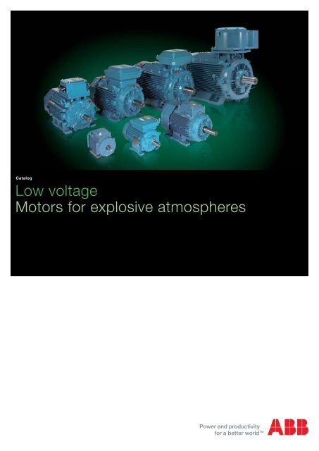
Low voltage Motors for explosive atmospheres - VAE ProSys sro
Low voltage Motors for explosive atmospheres - VAE ProSys sro
Low voltage Motors for explosive atmospheres - VAE ProSys sro
- No tags were found...

Create successful ePaper yourself
Turn your PDF publications into a flip-book with our unique Google optimized e-Paper software.
Catalog<br />
<strong>Low</strong> <strong>voltage</strong><br />
<strong>Motors</strong> <strong>for</strong> <strong>explosive</strong> <strong>atmospheres</strong>
We provide motors, generators and<br />
mechanical power transmission<br />
products, services and expertise to<br />
save energy and improve customers'<br />
processes over the total life cycle of<br />
our products, and beyond.<br />
2 LV <strong>Motors</strong> <strong>for</strong> <strong>explosive</strong> <strong>atmospheres</strong> EN 03-2013 / ABB <strong>Motors</strong> and Generators
<strong>Low</strong> <strong>voltage</strong> motors <strong>for</strong> <strong>explosive</strong><br />
<strong>atmospheres</strong><br />
Sizes 71 to 450, 0.25 to 1000 kW<br />
04 General in<strong>for</strong>mation<br />
16 Technical specifi cation<br />
27 Flameproof motors Ex d IIB/IIC T4 Gb<br />
53 Flameproof motors Ex de IIB/IIC T4 Gb<br />
83 Increased safety motors Ex e II T3 Gb<br />
113 Non-sparking motors Ex nA IE2/IE3<br />
161 Dust ignition protection motors /<br />
Protection by enclosure Ex t IIIB/<br />
IIIC T125 °C Db/Dc<br />
210 Total product offer<br />
ABB reserves the right to change the<br />
design, technical specification and<br />
dimensions without prior notice.<br />
211 Visit our web site<br />
ABB <strong>Motors</strong> and Generators / LV <strong>Motors</strong> <strong>for</strong> <strong>explosive</strong> <strong>atmospheres</strong> EN 03-2013 3
General in<strong>for</strong>mation<br />
M000701<br />
M000167<br />
ATEX Directives 94/9/EC (“95”) and 1999/92/EC (“137”)<br />
The ATEX Directives harmonize safety rules in line with the<br />
free trading principles of the European Community.<br />
Responsibilities are split between the manufacturers and end<br />
users. Manufacturers have to comply with the “Essential Health<br />
and Safety Requirements” of the Products Directive 94/9/EC,<br />
or ATEX 95; and end users must prepare an Explosion<br />
Protection Document based on risk assessments of their<br />
“work places” and “work equipment” to fulfi l the “minimum<br />
requirements” listed in the Worker Protection Directive<br />
1999/92/EC or ATEX 137.<br />
ABB low <strong>voltage</strong> motors <strong>for</strong> <strong>explosive</strong> <strong>atmospheres</strong> comply<br />
fully with the ATEX Products Directive 94/9/EC.<br />
According to the regulations, low <strong>voltage</strong> motors <strong>for</strong> <strong>explosive</strong><br />
<strong>atmospheres</strong> are exempted from the <strong>Low</strong> Voltage Directive,<br />
the EMC Directive and the Machinery Directive.<br />
IECEx System<br />
The IECEx System is a certification system which verifies<br />
compliance with IEC (International Electrotechnical<br />
Commission) standards relating to safety in <strong>explosive</strong><br />
<strong>atmospheres</strong>. It covers equipment, service facilities and the<br />
competency of personnel.<br />
Created in September 1999, the System aims “to facilitate<br />
international trade in equipment and services <strong>for</strong> use in<br />
<strong>explosive</strong> <strong>atmospheres</strong>, while maintaining the required level<br />
of safety…” (source: IECEx website, www.iecex.com). It is a<br />
voluntary system which provides an internationally accepted<br />
means of proving that products and services are in compliance<br />
with IEC standards. The voluntary and international aspects of<br />
the IECEx System differentiate it from certifi cation under ATEX,<br />
<strong>for</strong> example, which is mandatory but applies only within the<br />
European Economic Area.<br />
The IECEx System comprises global certification programs<br />
<strong>for</strong> both equipment and service facilities.<br />
IECEx certification involves – in addition to product tests<br />
– assessment of quality control procedures and testing<br />
plans, audits of manufacturing plants, and routine on-going<br />
surveillance and inspections.<br />
In addition, IECEx has established a comprehensive set of<br />
operational documents and procedures to develop a single<br />
internationally standardized approach to Ex testing and<br />
certification. The most important document is IECEx OD02,<br />
“Rules of procedure <strong>for</strong> equipment certification”.<br />
The approach includes:<br />
− A standardized “IECEx way of Ex Testing and Certification”.<br />
There is a single set of operational procedures, and Ex test<br />
procedures are always applied in the same way.<br />
− A dedicated Technical and Operational Secretariat to<br />
maintain operations. Ex test procedures are evaluated and<br />
monitored on a centralized basis.<br />
Who is responsible <strong>for</strong> the certification work<br />
A manufacturer needing to have equipment certified under<br />
the IECEx System can apply to an IECEx Competent Body<br />
(ExCB) in any member country. At present there are 30 IECEx<br />
member countries. The ExCB per<strong>for</strong>ms or coordinates the<br />
activities of certification.<br />
A quality assessment of the manufacturer is undertaken<br />
by the ExCB itself, and the auditor issues an IECEx Quality<br />
Assessment Report (QAR).<br />
Type testing of product samples is per<strong>for</strong>med on behalf of<br />
the ExCB by an IECEx Assessment and Testing Laboratory<br />
(ExTL). On completion of its work the ExTL’s assessment<br />
engineer prepares an IECEx Test Report (ExTR).<br />
The ExTR is then submitted to the ExCB <strong>for</strong> endorsement.<br />
Based on the QAR and ExTR, the ExCB then issues<br />
the Certificate of Con<strong>for</strong>mity (CoC). The CoC provides<br />
internationally accepted verification that the equipment in<br />
question is in compliance with the relevant IEC standards.<br />
Once <strong>for</strong>mally issued by the ExCB, both the ExTR and QAR<br />
are registered on the IECEx Internet site. This provides<br />
verification that an ExTR and QAR exist <strong>for</strong> the product and<br />
manufacturer.<br />
How do I know if a motor is IECEx certified<br />
IECEx certified motors show the certification number on their<br />
rating plate, <strong>for</strong> example: “IECEx LCI 05.0008”. In this case<br />
“LCI” indicates that the IECEx certificate was issued by LCIE,<br />
an IECEx approved Certification Body in France.<br />
In addition, IECEx certificates are issued in electronic <strong>for</strong>m<br />
and are publicly available on the IECEx website. They can<br />
there<strong>for</strong>e be viewed and printed by anyone with access to the<br />
Internet. See “Online Certificates” at www.iecex.com.<br />
IECEx certification is particularly useful in certain markets. In<br />
Australia, New Zealand, and Singapore, <strong>for</strong> example, IECEx<br />
certificates are accepted, but not all IEC certificates are<br />
accepted. Certain other countries, including Russia, China<br />
and Korea, are prepared to accept ExTRs as a basis <strong>for</strong> their<br />
4 LV <strong>Motors</strong> <strong>for</strong> <strong>explosive</strong> <strong>atmospheres</strong> EN 03-2013 / ABB <strong>Motors</strong> and Generators
own national certificates. There are also many countries that<br />
are willing to accept products covered by current IECEx<br />
certificates, even though the countries in question are not<br />
members of the IECEx Management Framework.<br />
Main standards <strong>for</strong> <strong>explosive</strong> <strong>atmospheres</strong>:<br />
IEC/EN 60079-0 Equipment - General requirements<br />
IEC/EN 60079-1 Equipment protection by flameproof enclosures “d”<br />
IECEx Con<strong>for</strong>mity Mark License<br />
The IECEx Con<strong>for</strong>mity Mark System was introduced in 2008.<br />
IECEx Con<strong>for</strong>mity Mark Licenses are issued by approved<br />
Certification Bodies in IECEx participating countries.<br />
The IECEx Con<strong>for</strong>mity Mark shows that a product has<br />
been granted an IECEx Certificate of Con<strong>for</strong>mity. IECEx<br />
Certification confirms that the product has the appropriate<br />
protection <strong>for</strong> use in <strong>explosive</strong> <strong>atmospheres</strong> and that it<br />
has been manufactured under systems subject to ongoing<br />
surveillance by Certification Bodies. It is recognized in all<br />
the countries participating in the IECEx System, and it also<br />
means that the product can be supplied to the market<br />
without the need <strong>for</strong> additional tests.<br />
IEC/EN 60079-7<br />
IEC/EN 60079-15<br />
IEC/EN 60079-31<br />
IEC/EN 60079-14<br />
IEC/EN 60079-17<br />
IEC/EN 60079-19<br />
IEC 60050-426<br />
IEC/EN 60079-10<br />
IEC 60079-10-1<br />
IEC 60079-10-2<br />
Equipment protection by increased safety “e”<br />
Equipment protection by type of protection “n”<br />
Equipment dust ignition protection by enclosure “t”<br />
Electrical installations design, selection and erection<br />
Electrical installations inspections and maintenance<br />
Equipment repair, overhaul and reclamation<br />
Equipment <strong>for</strong> <strong>explosive</strong> <strong>atmospheres</strong><br />
Classification of hazardous areas (gas areas)<br />
Classification of areas - Explosive gas <strong>atmospheres</strong><br />
Classification of areas - Combustible dust<br />
<strong>atmospheres</strong><br />
ABB has been granted IECEx Certification <strong>for</strong> a wide range of<br />
low and high <strong>voltage</strong> motors, and these can there<strong>for</strong>e display<br />
the IECEx Con<strong>for</strong>mity Mark. The hazardous area protection<br />
types provided by these motors include<br />
− Flameproof Ex d, Ex de<br />
− Non-sparking Ex nA<br />
− Dust protection Ex t<br />
The IECEx Con<strong>for</strong>mity Mark License will considerably<br />
enhance ABB’s ability to market its products globally. It<br />
complements ABB’s existing ATEX approval.<br />
Benefits of IECEx System <strong>for</strong> end users<br />
A significant advantage of IECEx is that vendor certificates<br />
are available <strong>for</strong> inspection on the IECEx website. End users<br />
can there<strong>for</strong>e confirm the validity of IECEx certificates at any<br />
time - which is not possible with ATEX, <strong>for</strong> example. This<br />
increases end user confidence that the motor vendor will be<br />
committed to maintaining the necessary quality systems.<br />
Equipment protection levels (EPLs)<br />
The latest revisions of the IEC and EN standards introduce the<br />
new concept of “equipment protection levels”, which identify<br />
products according to the ignition risk they might cause.<br />
A motor's EPL there<strong>for</strong>e indicates its inherent ignition risk,<br />
regardless of its protection type. This makes the selection of<br />
equipment <strong>for</strong> different zones easier. EPLs also enable a true<br />
risk assessment approach, where the potential consequences of<br />
a possible explosion are taken into consideration. Please refer<br />
to the table on the next page <strong>for</strong> more in<strong>for</strong>mation about EPLs<br />
and EPL markings.<br />
All ABB's cast iron motors <strong>for</strong> <strong>explosive</strong> <strong>atmospheres</strong>, have<br />
already been certified according to the EPL standards.<br />
Under the quality based IECEx certification approach the<br />
interpretation of the standard is shared throughout the<br />
30 participating countries and individual interpretations<br />
by Notified Bodies are not allowed. Another advantage of<br />
IECEx is that the Certificate of Con<strong>for</strong>mity also covers EPL<br />
(equipment protection level) “c”, see table on next page.<br />
Which ABB motors and generators are IECEx certified<br />
All M3JP/M3KP 80–450 motors with protection types Ex d<br />
and Ex de, M3GP 80-450 with protection type Ex nA and<br />
M3GP 80-400 with protection type Ex t are IECEx certified.<br />
Compliance on basis of recently updated standards<br />
In complying with the ATEX 95 and ATEX 137 Directives, ABB<br />
follows the requirements of recently updated IEC and EN<br />
standards. Otherwise ABB follows the requirements of the<br />
IEC standards shown in the relevant certificates.<br />
ABB <strong>Motors</strong> and Generators / LV <strong>Motors</strong> <strong>for</strong> <strong>explosive</strong> <strong>atmospheres</strong> EN 03-2013 5
Explosive <strong>atmospheres</strong><br />
There are systems in place worldwide to classify <strong>explosive</strong><br />
<strong>atmospheres</strong> by zones, according to the risk posed by<br />
<strong>explosive</strong> gas (“G”) or dust (“D”).<br />
Ex d(e) II...<br />
Ex e II...<br />
Ex p II...<br />
Ex t III...<br />
Gb<br />
Gb<br />
Gb<br />
Db<br />
Ex nA II...<br />
Ex t III...<br />
Gc<br />
Dc<br />
M000168<br />
Zone 2 (“G”) / 22 (“D”)<br />
Abnormal condition<br />
Presence of <strong>explosive</strong> atmosphere<br />
only by accident, but not during<br />
normal duty<br />
Equipment protection level “c” required<br />
Zone 1 (“G”) / 21 (“D”)<br />
Occasionally<br />
Incidental presence of <strong>explosive</strong><br />
atmosphere during normal duty<br />
Equipment protection level “b” required<br />
Zone 0 (“G”) / 20 (“D”)<br />
Continuously<br />
Permanent presence of<br />
<strong>explosive</strong> atmosphere<br />
Equipment protection level<br />
“a” required<br />
M000176 M000169<br />
Classifi cation of <strong>explosive</strong> <strong>atmospheres</strong> according to CENELEC<br />
and IEC<br />
The following standards defi ne areas according to the presence<br />
of gas or dust in the atmosphere:<br />
IEC/EN 60079-10-1 Gas<br />
IEC/EN 60079-10-2 Dust<br />
Standard<br />
Installation<br />
ATEX Directive<br />
Main motor<br />
IEC 60079-0<br />
Zone acc. to<br />
94/9/EC<br />
protection<br />
EN 60079-0<br />
IEC 60079-10-x<br />
types<br />
EN 60079-10-x<br />
Group EPL Protection level Zones Equipment group Equipment category<br />
I<br />
Ma very high NA I<br />
M1<br />
NA<br />
(Mines)<br />
Mb high (Mines)<br />
M2<br />
Ga very high 0<br />
1G<br />
NA<br />
II<br />
(Gas)<br />
Gb high 1 2G Ex d/Ex de<br />
Ex p, Ex e<br />
Gc enhanced 2 II<br />
3G Ex nA<br />
Da very high 20 (Surface)<br />
1D NA<br />
III<br />
Db high 21 2D Ex tb IP 65<br />
(Dust)<br />
Dc enhanced 22 3D Ex tc<br />
IP 65/IP 55<br />
6 LV <strong>Motors</strong> <strong>for</strong> <strong>explosive</strong> <strong>atmospheres</strong> EN 03-2013 / ABB <strong>Motors</strong> and Generators
Marking of temperatures, gas groups and <strong>explosive</strong> <strong>atmospheres</strong><br />
To ensure equipment can be safely used in potentially<br />
<strong>explosive</strong> <strong>atmospheres</strong>, the <strong>explosive</strong> <strong>atmospheres</strong> where<br />
the equipment is installed must be known. The temperature<br />
class of equipment must be compared with the spontaneous<br />
ignition the equipment of the gas mixtures concerned, and<br />
in specific cases the gas group must be known (e.g. flame<br />
proof protection).<br />
Classifi cation<br />
Gas classification<br />
Temperature<br />
Ignition Max. permitted Gas examples<br />
class temp. of gas/<br />
vapor °C<br />
temp. of equipment<br />
°C<br />
T1 > 450 450 Hydrogen<br />
T2 > 300 < 450 300 Ethanol<br />
T3 > 200 < 300 200 Hydrogen sulfi de<br />
Gas subdivision<br />
IIA ~120 gases and vapors, e.g. butane / petroleum /<br />
propane<br />
IIB ~30 gases and vapors, e.g. ethylene / dimethyl ether /<br />
coke oven gas<br />
IIC<br />
three gases: hydrogen H 2<br />
/acetylene C 2<br />
H 2<br />
carbon<br />
disulfide CS 2<br />
T4 > 135 < 200 135 Diethyl ether<br />
T5 > 100 < 135 100 -<br />
T6 > 85 < 100 85 Carbon disulfi de<br />
Marking of equipment protection <strong>for</strong> gas according to ATEX<br />
CE Con<strong>for</strong>mity marking<br />
Equipment protection marking <strong>for</strong> gas:<br />
CE marking<br />
0081<br />
II 2G<br />
Ex d IIB T4 Gb<br />
Identification<br />
of the notified body<br />
responsible <strong>for</strong> the<br />
approval. 0081 is the<br />
identification number of LCIE<br />
Protection type Ex d = flameproof<br />
Equipment group IIB <strong>for</strong> gas group B<br />
Temperature class T4 = max. permitted 135 °C<br />
Equipment protection level = level b <strong>for</strong> gas<br />
The European Commission<br />
mark <strong>for</strong> Ex products<br />
Equipment group: II <strong>for</strong> surface industry<br />
Equipment category: 2G <strong>for</strong> gas<br />
environment demanding a high<br />
level of protection<br />
Marking of equipment protection <strong>for</strong> gas according to IEC<br />
Example <strong>for</strong> gas:<br />
Ex d IIB T4 Gb<br />
Protection type Ex d = flameproof<br />
Equipment group IIB <strong>for</strong> gas group B<br />
Temperature class T4 = max. permitted 135 °C<br />
Equipment protection level = level b <strong>for</strong> gas<br />
ABB <strong>Motors</strong> and Generators / LV <strong>Motors</strong> <strong>for</strong> <strong>explosive</strong> <strong>atmospheres</strong> EN 03-2013 7
Selection of products <strong>for</strong> <strong>explosive</strong> <strong>atmospheres</strong><br />
EN Standard and ATEX Directive <strong>for</strong> gas environments<br />
EN 60079-0: General requirements<br />
EN 60079-1<br />
Flameproof enclosure<br />
“d”<br />
EN 60079-7<br />
Increased safety<br />
“e”<br />
EN 60079-15<br />
Non-sparking<br />
“n”<br />
Category 2G<br />
Category 2G<br />
Category 3G<br />
ATEX directive<br />
marking<br />
... II 2G ... II 2G<br />
II 3G<br />
Equipment<br />
protection<br />
marking<br />
Environment<br />
Ex d IIB T4 Gb Ex e IIC T3 Gb Ex nA IIC T3 Gc<br />
Zone 1 Zone 1 Zone 2<br />
EN 60079-14: Installations design, selection and erection<br />
M000170a<br />
General in<strong>for</strong>mation about <strong>explosive</strong> <strong>atmospheres</strong><br />
Preamble<br />
In <strong>explosive</strong> <strong>atmospheres</strong>, it is of the utmost importance<br />
to ensure the safe use of electrical apparatus. To this end,<br />
many countries have regulations concerning both the design<br />
and use of such apparatus. These regulations are becoming<br />
increasingly harmonized within the framework of IEC<br />
recommendations and European Standards. The hazard may<br />
be due to an <strong>explosive</strong> atmosphere composed of a mixture of<br />
gas, vapors or dusts with air. This section is concerned only<br />
with safety in <strong>explosive</strong> gas <strong>atmospheres</strong> <strong>for</strong> which European<br />
Standards and IEC recommendations exist.<br />
Flameproof enclosure Ex d<br />
and Ex de<br />
The motor enclosure is designed in such a way that no<br />
internal explosion can be transmitted to the <strong>explosive</strong><br />
atmosphere surrounding the motor. The enclosure must<br />
withstand, without damage, any pressure levels caused by<br />
an internal explosion. The shape, length and gap of joints of<br />
part assemblies, at shaft openings, cable entries, etc., shall<br />
be designed to allow <strong>for</strong> throttling and cooling of hot gases<br />
escaping outside. The standards emphasize the impact of an<br />
<strong>explosive</strong> atmosphere (<strong>for</strong> instance, explosion pressure) over<br />
constructional requirements of such apparatus.<br />
8 LV <strong>Motors</strong> <strong>for</strong> <strong>explosive</strong> <strong>atmospheres</strong> EN 03-2013 / ABB <strong>Motors</strong> and Generators
Work on accessories of enclosure componenets is only<br />
permitted using prescribed tools. Cable entries must meet<br />
the requirements of this type of protection.<br />
The temperature of the motor's external enclosure shall<br />
not exceed the self-ignition temperature of the <strong>explosive</strong><br />
atmosphere of the installation area during operation. For<br />
this reason, rated output depends on this rated maximum<br />
temperature <strong>for</strong> the area in question.<br />
No motor device outside the flameproof enclosure (e.g.,<br />
ventilator) shall be a potential source of sparks, arcs or<br />
dangerous overheating.<br />
Variants combining two types of protection usually combine<br />
“d” and “e” protection. The motor is designed with an Ex<br />
d flameproof enclosure, while the terminal box features Ex<br />
e increased safety protection. Such design combines the<br />
superior safety degree of the “d” type of protection with the<br />
high electrical connection requirements of increased safety<br />
motors.<br />
Alleinschutz – thermistors as sole protection (optional)<br />
Flameproof motors from ABB have been designed to<br />
use thermistors as the sole method of protection against<br />
overload. This construction, “Alleinschutz”, is available as an<br />
option, see variant codes.<br />
“Alleinschutz” refers to the protection of a flameproof motor<br />
by a protective device which is triggered by thermistors. The<br />
thermistors and relays will switch off the motor in case of<br />
overheating be<strong>for</strong>e the temperature of the motor's external<br />
enclosure exceeds the temperature marking stamped on the<br />
rating plate.<br />
Each motor ordered with thermistors as sole protection<br />
will be tested, with locked rotor, up to the point where<br />
the thermistors trigger the relay to turn off the motor. At<br />
the triggering temperature, the motor has to be within the<br />
certified temperature class limit.<br />
Only approved relays can be used <strong>for</strong> “Alleinschutz”.<br />
Please note that sizes 315 to 450 require special technical<br />
solutions, consult ABB.<br />
Dual certification<br />
Ex d/de motors can also be used <strong>for</strong> Dust/Ex t applications in<br />
zone 21. The following combinations are possible:<br />
− Ex tb IIIB T125 °C Db, IP 65 <strong>for</strong> zone 21 + Ex d/de IIB/<br />
C T3 Gb<br />
− Ex tb IIIC T125 °C Db, IP 65 <strong>for</strong> zone 21 + Ex d/de IIB/<br />
C T3 Gb<br />
These features are possible due to the IP protection.<br />
The ingress of dust is prevented and thus only the outside<br />
surface temperature class is important <strong>for</strong> both applications;<br />
T4 (=135 °C) <strong>for</strong> gas and T125 °C <strong>for</strong> dust.<br />
Increased safety design, Ex e<br />
The design of this motor type prevents the occurence in<br />
operation (including starting and locked rotor situations), in<br />
all inner and outer parts of the machine, of sparks, arcs or<br />
hot spots that could reach the self-ignition temperature of the<br />
surrounding, potentially <strong>explosive</strong> atmosphere.<br />
This is ensured by applying constructional or dimensional<br />
provisions that mainly concern:<br />
− specified minimum values <strong>for</strong> creepage distances and<br />
clearances<br />
− use of tracking-proof isolating materials<br />
− suppression of sharp angles where static electrical loads<br />
could build-up<br />
− ensuring electrical and mechanical assemblies are tightly<br />
secured<br />
− minimum backlash values between stationary and rotating<br />
parts (e.g. air gap, ventilator, etc.)<br />
− temperature-rise limits, taking into account locked rotor,<br />
normal operation, accidental mechanical stalling of<br />
machine under the most adverse thermal conditions, i.e.<br />
when thermal equilibrium of machine is reached while in<br />
service.<br />
Temperature rise limits should be considered <strong>for</strong> two<br />
operating aspects; normal operating conditions and<br />
accidental stalling conditions.<br />
ABB <strong>Motors</strong> and Generators / LV <strong>Motors</strong> <strong>for</strong> <strong>explosive</strong> <strong>atmospheres</strong> EN 03-2013 9
Temperature rise limits under normal operating<br />
conditions<br />
The expected electrical lifespan of a motor depends on its<br />
temperature rise <strong>for</strong> a given insulation class, and on the<br />
motor winding temperature, during operation, which is not<br />
homogeneous due to the appearance of hot spots. For<br />
these reasons, a safety margin of 10 K is allowed between<br />
the winding's temperature rise at rated output, as measured<br />
by the change of resistance method, and the maximum<br />
temperature rise permitted by the winding insulation class.<br />
M000172<br />
M000173<br />
Figure 2. Min. value of time t E<br />
as a function of I A<br />
/I N<br />
acc. to<br />
IEC/EN 60019-7<br />
Figure 1.<br />
O = Temperature 0 °C<br />
A = Max. ambient temperature, reference 40 °C<br />
B = Temperature at rated load and under worst <strong>voltage</strong><br />
conditions<br />
C = Max temperature as permitted by the insul. class<br />
D = Max limit temperature as set by the nature of the<br />
potentially <strong>explosive</strong> atmosphere<br />
E = Temperature-rise curve of motor at rated output and<br />
under worst <strong>voltage</strong> conditions<br />
F = Temp. rise curve under stalled rotor conditions<br />
t E<br />
= Stalled rotor time<br />
Figure 3. Min. value of time t E<br />
as a function of I A<br />
/I N<br />
acc. to<br />
VIK.<br />
Non-sparking design, Ex nA<br />
M000174<br />
Temperature rise limits during short circuit under<br />
accidental stalling conditions<br />
Should the machine stall while in operation, a shortcircuit<br />
current nearly equal to the starting current will develop, and<br />
stator and rotor winding temperatures will rise rapidly (see<br />
Figure 1).<br />
To prevent this temperature value from exceeding the<br />
maximum limit temperature as set by the nature of the<br />
potentially <strong>explosive</strong> atmosphere (D in Figure 1), protection<br />
devices must trip within a specified time (t E<br />
). This tripping<br />
time depends on the short-circuit current level or the shortcircuit<br />
current to rated current ratio (I A<br />
/I N<br />
). Figures 2 and 3<br />
show, <strong>for</strong> commonly used protection devices, the limiting<br />
ratio between short-circuit current inrush I A<br />
/I N<br />
and rotor<br />
stalling time t E<br />
, according to the EN and IEC standards and<br />
“VIK” specification. VIK is an industry specification originating<br />
in Germany.<br />
This type of protection is inappropriate <strong>for</strong> commutator<br />
machines or brake-motors which, by principle, are capable<br />
of producing arcs, sparks or hot spots.<br />
The use of this type of protection is allowed in hazardous<br />
areas corresponding to zone 2. The design is known as “nonsparking”<br />
because the motor must be designed in such a<br />
way that no sparks can occur in any conditions, when used<br />
within the ratings specifi ed by the manufacturer, and that<br />
no excessive temperatures occur under normal operating<br />
conditions, which excludes thermal requirements due to<br />
starting or accidental stalling.<br />
Ex nA motors are certifi ed according to the ATEX 95 Directive<br />
with a “voluntary type examination certifi cate”, and according<br />
to the IEC Ex System with a normal certifi cate.<br />
ABB also provides self-certifi ed non-sparking motors, with a<br />
manufacturer Declaration of Con<strong>for</strong>mity.<br />
Dual certification<br />
Ex nA motors with a cast iron frame can also be used <strong>for</strong> Dust/<br />
Ex t –applications in zone 22. The following combinations are<br />
possible:<br />
– Ex tc IIIB T125 °C Dc, IP 55 <strong>for</strong> zone 22 + Ex nA IIC T3<br />
– Ex tc IIIC T125 °C Dc, IP 65 <strong>for</strong> zone 22 + Ex nA IIC T3<br />
10 LV <strong>Motors</strong> <strong>for</strong> <strong>explosive</strong> <strong>atmospheres</strong> EN 03-2013 / ABB <strong>Motors</strong> and Generators
These features are possible due to the IP protection. Gases<br />
penetrate this protection, and thus the inside surface<br />
temperature class is T3 (200 °C). The ingress of dust,<br />
however, is prevented and dust determines the outside surface<br />
temperature class: T125°C.<br />
Risk assessment and gas tests<br />
Non-sparking (Ex nA) and increased safety (Ex e) motors<br />
have to meet tough requirements with regard to sparking.<br />
The latest IEC and EN standards specify criteria <strong>for</strong> risk<br />
assessment and gas environment tests <strong>for</strong> rotor and stator<br />
designs to show that the motors are spark-free in all<br />
operational conditions.<br />
By testing and securing certification <strong>for</strong> its motors, ABB is<br />
helping to streamline the risk assessment process <strong>for</strong> its<br />
customers.<br />
The alternative to testing and certification involves, in the<br />
majority of cases, equipping the motor with provision <strong>for</strong><br />
pre-start ventilation. This means investing in a higher capacity<br />
air compressor, piping, and a ventilation control unit. It also<br />
requires an additional operation – pre-start ventilation – every<br />
time the motor is started.<br />
Benefi ts of the ABB approach there<strong>for</strong>e include reduced initial<br />
capital expenditure, lower operating costs, and faster starting.<br />
Reliability is improved as no additional components are required.<br />
Most importantly, ABB’s certifi ed motors offer proven safety.<br />
ABB’s approach to meeting the new requirements<br />
Following a program of gas environment tests in which<br />
all rotor and stator tests were passed, ABB has secured<br />
certification <strong>for</strong> its low <strong>voltage</strong> cast iron motors <strong>for</strong> <strong>explosive</strong><br />
<strong>atmospheres</strong> with aluminum die cast rotor.<br />
Dust ignition protection / Protection by enclosures “t”<br />
in <strong>explosive</strong> <strong>atmospheres</strong><br />
Combustible dust is hazardous as it can <strong>for</strong>m potentially<br />
<strong>explosive</strong> <strong>atmospheres</strong> when dispersed in air. Furthermore,<br />
layers of combustible dust may ignite and act as an ignition<br />
source <strong>for</strong> an <strong>explosive</strong> atmosphere. Explosive <strong>atmospheres</strong><br />
with dust can be found in a variety of industries such as<br />
agriculture, chemicals, plastics, food and beverage.<br />
Selection and installation of electrical equipment<br />
To ensure equipment can be safely used in <strong>explosive</strong><br />
<strong>atmospheres</strong> with dust, it is vital that the following issues are<br />
taken into account when selecting product:<br />
1. Type of dust:<br />
− Will a cloud of dust be present around the product or<br />
− will a layer of dust build up on the product and if so, what<br />
will be the maximum thickness of the layer between two<br />
cleaning/maintenance procedures.<br />
This protection prevents any explosion of dust because:<br />
− The ingress of dust into the motor is prevented by the IP<br />
protection, being either IP 55 (“dust protected”) or<br />
IP 65 (“dust tight”).<br />
− The maximum surface temperature outside the motor must<br />
not exceed the temperature class <strong>for</strong> which the motor is<br />
certified.<br />
− No sparks must occur outside the motor enclosure.<br />
Certification: Ex tb IIIB/C T...°C Db (<strong>for</strong> zone 21) motors are<br />
certified according to ATEX with an EC type examination<br />
certificate and according to the IEC Ex System. Ex tc IIIB/C<br />
T...°C Dc (<strong>for</strong> zone 22) motors are certified according to ATEX<br />
with a “voluntary type examination certificate” and according<br />
to the IEC Ex System.<br />
2. Characteristics of the dust:<br />
− Is the dust electrically conductive or non-conductive<br />
3. Ignition temperature of the dust:<br />
− T Cl<br />
: Ignition temperature of dust in a “cloud” or<br />
− T 5mm<br />
: Ignition temperature of a 5 mm dust layer<br />
Selection and installation of the product according to IEC/<br />
EN60079 part 14: Electrical installations design, selection<br />
and erection. Please see the tables on the pages 12 and 13.<br />
ABB <strong>Motors</strong> and Generators / LV <strong>Motors</strong> <strong>for</strong> <strong>explosive</strong> <strong>atmospheres</strong> EN 03-2013 11
Dust classification<br />
T CL<br />
(cloud)<br />
°C<br />
T 5mm<br />
(layer)<br />
°C<br />
Surface temperature<br />
provided that dust<br />
layer below 5 mm<br />
Food/Feeder Wheat 350 270 195<br />
industry<br />
Barley, corn 380 280 205<br />
Sugar 350 430 233<br />
Natural materials Wood 330 280 205<br />
Charcoal 520 230 195<br />
Hard coal 460 240 165<br />
Chemicals PVC 450 330 255<br />
Synth. rubber 470 220 145<br />
Sulfur 240 250 160<br />
Source BIA-report 13/97 HVBG<br />
Dust subdivisions<br />
IIIA<br />
IIIB<br />
IIIC<br />
combustible fl yings<br />
non-conductive dust<br />
conductive dust<br />
Marking of equipment protection <strong>for</strong> dust according to ATEX<br />
CE Con<strong>for</strong>mity marking<br />
Equipment protection <strong>for</strong> dust:<br />
CE marking<br />
0081<br />
II 2 D<br />
Ex tc IIIC T125 °C Dc<br />
Identification<br />
of the notified body<br />
responsible <strong>for</strong> the<br />
approval. 0081 is the<br />
identification number of LCIE<br />
The European Commission<br />
mark <strong>for</strong> Ex products<br />
Protection<br />
by enclosure<br />
Equipment group IIIC<br />
<strong>for</strong> conductive dust<br />
Temperature class<br />
Equipment protection level = level c <strong>for</strong> dust<br />
Equipment group: II <strong>for</strong> surface industry<br />
Equipment category: 2D <strong>for</strong> dust<br />
environment demanding a high<br />
level of protection<br />
Marking of equipment protection <strong>for</strong> dust according to IEC<br />
Example <strong>for</strong> dust:<br />
Ex tc IIIC T125 °C Dc<br />
Protection<br />
by enclosure<br />
Equipment group IIIC<br />
<strong>for</strong> conductive dust<br />
Temperature class<br />
Equipment protection level = level c <strong>for</strong> dust<br />
12 LV <strong>Motors</strong> <strong>for</strong> <strong>explosive</strong> <strong>atmospheres</strong> EN 03-2013 / ABB <strong>Motors</strong> and Generators
Selection of products <strong>for</strong> <strong>explosive</strong> <strong>atmospheres</strong><br />
EN Standard and ATEX Directive <strong>for</strong> dust environments<br />
EN 60079-0: General requirements<br />
EN 60079-31: Protection by enclosure ”t”<br />
Category 2D<br />
Category 2D Category 3D Category 3D<br />
ATEX directive<br />
marking<br />
... II 2D ... II 2D II 3D II 3D<br />
Equipment<br />
protection<br />
marking<br />
Ex tb IIIC<br />
T125°C Db<br />
Ex tb IIIB<br />
T125°C Db<br />
Ex tc IIIC<br />
T125°C Dc<br />
Ex tc IIIB<br />
T125°C Dc<br />
IP class<br />
marking<br />
IP65 IP65 IP65 IP55<br />
Conductive<br />
dust<br />
Non-conductive<br />
dust<br />
Conductive<br />
dust<br />
Non-conductive<br />
dust<br />
Environment<br />
Zone 21 Zone 21 Zone 22 Zone 22<br />
EN 60079-14: Installations design, selection and erection<br />
M000171a<br />
Testing and certifi cates<br />
<strong>Motors</strong> <strong>for</strong> <strong>explosive</strong> <strong>atmospheres</strong> have to be officially<br />
approved by a recognized test organization, authorized to<br />
issue test certificates, to ensure compliance with standards<br />
<strong>for</strong> this type of equipment.<br />
ABB low <strong>voltage</strong> motors <strong>for</strong> <strong>explosive</strong> <strong>atmospheres</strong> are<br />
classified according to the categories, protection types and<br />
equipment protection type which are specified in the relevant<br />
standards.<br />
Depending on the nature of the potentially <strong>explosive</strong><br />
atmosphere, it is the responsibility of the user to determine<br />
which group and which maximum surface temperature should<br />
be specified <strong>for</strong> the motor installation.<br />
The motors are rated and certified <strong>for</strong> ambient temperature<br />
between –20 °C and +40 °C according to standards. For<br />
ambient temperatures below –20 °C and above +40 °C<br />
certificates are available <strong>for</strong> most of the motors.<br />
ABB’s motors con<strong>for</strong>m to the stringent standards set<br />
by CENELEC (European Committee <strong>for</strong> Electrotechnical<br />
Standardization) and IEC (International Electrotechnical<br />
Commission), and are approved by testing laboratories<br />
(ExNB/Notified Body) and certification bodies (ExCB).<br />
The motors can be certified according to the ATEX Directive<br />
by any of the Notified Bodies “ExNB” of EU member<br />
countries. These motors are there<strong>for</strong>e acceptable in all EU<br />
countries and many other countries. In addition, IECEx<br />
certificates are available <strong>for</strong> the motors. These certificates<br />
can be issued by any registered IECEx certification body<br />
(ExCB) worldwide.<br />
Typical national certificates available include GOST-R <strong>for</strong><br />
Russia, GOST-K <strong>for</strong> Kazakhstan, INMETRO <strong>for</strong> Brazil and<br />
CQST <strong>for</strong> China. KOSHA certification <strong>for</strong> Korea is different,<br />
because the organization importing the motor to Korea has to<br />
apply on a case-by-case basis, and ABB delivers the required<br />
documentation to KOSHA in order to receive certification.<br />
Such national certifications are mainly obtained on the basis<br />
of IECEx or ATEX.<br />
ABB <strong>Motors</strong> and Generators / LV <strong>Motors</strong> <strong>for</strong> <strong>explosive</strong> <strong>atmospheres</strong> EN 03-2013 13
International motor effi ciency standards<br />
Since the validation of standard IEC/EN 60034-30, a<br />
worldwide energy efficiency classification system has existed<br />
<strong>for</strong> low <strong>voltage</strong> three-phase asynchronous motors. This<br />
system increases the level of harmonization in efficiency<br />
regulations around the world and it also covers motors <strong>for</strong><br />
<strong>explosive</strong> <strong>atmospheres</strong>. IEC/EN 60034-30:2008 defines<br />
International Efficiency (IE) classes <strong>for</strong> single speed, threephase,<br />
50 and 60 Hz induction motors. The standard is<br />
part of an ef<strong>for</strong>t to unify motor testing procedures as well as<br />
efficiency and product labeling requirements to enable motor<br />
purchasers worldwide to easily recognize premium efficiency<br />
products. The efficiency levels defined in IEC/EN 60034-30<br />
are based on test methods specified in IEC/EN 60034-2-<br />
1:2007.<br />
To promote transparency in the market, IEC 60034-30<br />
states that both the efficiency class and efficiency value<br />
must be shown on the motor rating plate and in product<br />
documentation. The documentation must clearly indicate the<br />
efficiency testing method used as the different methods can<br />
produce differing results.<br />
As the scope of IEC/EN 60034-30 also covers <strong>for</strong> <strong>explosive</strong><br />
<strong>atmospheres</strong>, these motors can be labeled with the IE -code.<br />
Ex-motors are already included in many MEPS (Minimum<br />
Energy Per<strong>for</strong>mance Standard) schemes around the world;<br />
Australia, the US, Canada, China, Korea and Brazil.<br />
= Requirements <strong>for</strong> efficiency<br />
= Requirements/Ex-certification<br />
CSA Energy<br />
Efficiency<br />
Verification<br />
GOST<br />
CSA<br />
EU MEPS<br />
STB<br />
EPAct,<br />
NEMA Premium<br />
NEC/UL<br />
ATEX (Europe)<br />
Turkish MEPS<br />
GOST-K<br />
China<br />
Energy Label<br />
CQST<br />
Korean MEPS<br />
Kosha<br />
Taiwan ITRI<br />
JIS C4210/12<br />
JIS<br />
Mexican MEPS<br />
PESO<br />
PBE – Brazilian<br />
Labelling Program<br />
Inmetro<br />
QAS<br />
AU MEPS<br />
SABS<br />
IECEx (Worldwide)<br />
M000700<br />
14 LV <strong>Motors</strong> <strong>for</strong> <strong>explosive</strong> <strong>atmospheres</strong> EN 03-2013 / ABB <strong>Motors</strong> and Generators
IEC/EN 60034-30:2008<br />
IEC/EN 60034-30:2008 defines three International Efficiency<br />
(IE) classes <strong>for</strong> single speed, three-phase, cage induction<br />
motors. Additionally, IEC/TS 60034-31 specifies efficiency<br />
class IE4.<br />
− IE1 = Standard efficiency (EFF2 in the <strong>for</strong>mer European<br />
classification scheme)<br />
− IE2 = High efficiency (EFF1 in the <strong>for</strong>mer European<br />
classification scheme and identical to EPAct in the USA<br />
<strong>for</strong> 60 Hz)<br />
− IE3 = Premium efficiency (identical to “NEMA Premium”<br />
in the USA <strong>for</strong> 60 Hz)<br />
− IE4 = Super premium, according to IEC/TS 60034-31<br />
Efficiency levels defined in IEC/EN 60034-30 are based on<br />
test methods specified in IEC/EN 60034-2-1:2007.<br />
Compared to the <strong>for</strong>mer European efficiency classes defined<br />
by the CEMEP agreement the scope has been expanded.<br />
IEC/EN 60034-30 covers almost all motors (<strong>for</strong> example<br />
standard, hazardous area, marine, brake motors)<br />
− Single speed, three-phase, 50 Hz and 60 Hz<br />
− 2-, 4- or 6-pole<br />
− Rated output from 0.75 to 375 kW<br />
− Rated <strong>voltage</strong> U N<br />
up to 1000 V<br />
− Duty type S1 (continuous duty) or S3 (intermittent periodic<br />
duty) with a rated cyclic duration factor of 80 % or higher<br />
− Capable of operating direct online<br />
Minimum efficiency values defined in IEC 60034-30:2008<br />
(based on test methods specified in<br />
IEC 60034-2-1:2007)<br />
Output<br />
IE1<br />
Standard effi ciency<br />
IE2<br />
High effi ciency<br />
IE3<br />
Premium effi ciency<br />
kW 2 pole 4 pole 6 pole 2 pole 4 pole 6 pole 2 pole 4 pole 6 pole<br />
0.75 72.1 72.1 70.0 77.4 79.6 75.9 80.7 82.5 78.9<br />
1.1 75.0 75.0 72.9 79.6 81.4 78.1 82.7 84.1 81.0<br />
1.5 77.2 77.2 75.2 81.3 82.8 79.8 84.2 85.3 82.5<br />
2.2 79.7 79.7 77.7 83.2 84.3 81.8 85.9 86.7 84.3<br />
3 81.5 81.5 79.7 84.6 85.5 83.3 87.1 87.7 85.6<br />
4 83.1 83.1 81.4 85.8 86.6 84.6 88.1 88.6 86.8<br />
5.5 84.7 84.7 83.1 87.0 87.7 86.0 89.2 89.6 88.0<br />
7.5 86.0 86.0 84.7 88.1 88.7 87.2 90.1 90.4 89.1<br />
11 87.6 87.6 86.4 89.4 89.8 88.7 91.2 91.4 90.3<br />
15 88.7 88.7 87.7 90.3 90.6 89.7 91.9 92.1 91.2<br />
18.5 89.3 89.3 88.6 90.9 91.2 90.4 92.4 92.6 91.7<br />
22 89.9 89.9 89.2 91.3 91.6 90.9 92.7 93.0 92.2<br />
30 90.7 90.7 90.2 92.0 92.3 91.7 93.3 93.6 92.9<br />
37 91.2 91.2 90.8 92.5 92.7 92.2 93.7 93.9 93.3<br />
45 91.7 91.7 91.4 92.9 93.1 92.7 94.0 94.2 93.7<br />
55 92.1 92.1 91.9 93.2 93.5 93.1 94.3 94.6 94.1<br />
75 92.7 92.7 92.6 93.8 94.0 93.7 94.7 95.0 94.6<br />
90 93.0 93.0 92.9 94.1 94.2 94.0 95.0 95.2 94.9<br />
110 93.3 93.3 93.3 94.3 94.5 94.3 95.2 95.4 95.1<br />
132 93.5 93.5 93.5 94.6 94.7 94.6 95.4 95.6 95.4<br />
160 93.7 93.8 93.8 94.8 94.9 94.8 95.6 95.8 95.6<br />
200 94.0 94.0 94.0 95.0 95.1 95.0 95.8 96.0 95.8<br />
250 94.0 94.0 94.0 95.0 95.1 95.0 95.8 96.0 95.8<br />
315 94.0 94.0 94.0 95.0 95.1 95.0 95.8 96.0 95.8<br />
355 94.0 94.0 94.0 95.0 95.1 95.0 95.8 96.0 95.8<br />
375 94.0 94.0 94.0 95.0 95.1 95.0 95.8 96.0 95.8<br />
The following motors are excluded from IEC 60034-30:<br />
− <strong>Motors</strong> made solely <strong>for</strong> converter operation<br />
− <strong>Motors</strong> completely integrated into a machine (<strong>for</strong> example,<br />
pump, fan or compressor) that cannot be tested separately<br />
from the machine<br />
ABB and efficiency standards<br />
As a global player committed to supplying safe, reliable<br />
and efficient motors, ABB designs and labels its motors <strong>for</strong><br />
<strong>explosive</strong> <strong>atmospheres</strong> to comply with international efficiency<br />
standards published by the IEC. ABB determines efficiency<br />
values according to IEC/EN 60034-2-1 using the low<br />
uncertainty method (i.e. indirect method), with additional load<br />
losses determined by measurement.<br />
As the world market leader, ABB offers the largest range<br />
of LV motors available. It has long advocated the need<br />
<strong>for</strong> efficiency in motors, and high efficiency products have<br />
<strong>for</strong>med the core of its portfolio <strong>for</strong> many years. The core of<br />
ABB's Ex range is based on a full range of IE2 motors – with<br />
many available from stock. Premium efficiency IE3 motors are<br />
also available <strong>for</strong> a major part of the range.<br />
ABB <strong>Motors</strong> and Generators / LV <strong>Motors</strong> <strong>for</strong> <strong>explosive</strong> <strong>atmospheres</strong> EN 03-2013 15
<strong>Low</strong> <strong>voltage</strong> general technical specifi cation<br />
Mechanical and electrical design<br />
Mounting arrangements<br />
Code I/Code II Product code pos. 12<br />
Foot-mounted motor. IM B3 IM V5 IM V6 IM B6 IM B7 IM B8 A = foot-mounted,<br />
IM 1001 IM 1011 IM 1031 IM 1051 IM 1061 IM 1071<br />
term.box top<br />
R = foot-mounted,<br />
term.box RHS<br />
L = foot-mounted,<br />
term.box LHS<br />
Flange-mounted motor, IM B5 IM V1 IM V3 *) *) *) B = fl ange mounted,<br />
large fl ange IM 3001 IM 3011 IM 3031 IM 3051 IM 3061 IM 3071 large fl ange<br />
M000007<br />
Flange-mounted motor, IM B14 IM V18 IM V19 *) *) *) C = fl ange mounted,<br />
small fl ange IM 3601 IM 3611 IM 3631 IM 3651 IM 3661 IM 3671 small fl ange<br />
Foot- and fl ange-mounted IM B35 IM V15 IM V36 *) *) *) H = foot/fl ange-mounted,<br />
motor with feet, IM 2001 IM 2011 IM 2031 IM 2051 IM 2061 IM 2071 term.box top<br />
large fl ange<br />
S = foot/fl ange-mounted,<br />
term.box RHS<br />
T = foot/fl ange-mounted,<br />
term.box LHS<br />
Foot- and fl ange-mounted IM B34 IM V17<br />
motor with feet, IM 2101 IM 2111 IM 2131 IM 2151 IM 2161 IM 2171 J = foot/fl ange-mounted,<br />
small fl ange<br />
small fl ange<br />
Foot-mounted motor,<br />
shaft with free extensions IM 1002 IM 1012 IM 1032 IM 1052 IM 1062 IM 1072<br />
M000012<br />
M000011<br />
M000009<br />
M000008<br />
M000010<br />
*) Not stated in IEC 60034-7.<br />
Note: In the case of motors mounted with the shaft upwards , the user must provide some means to prevent water or other<br />
liquids from running down the shaft where this is expected to occur.<br />
16 LV <strong>Motors</strong> <strong>for</strong> <strong>explosive</strong> <strong>atmospheres</strong> EN 03-2013 / ABB <strong>Motors</strong> and Generators
Voltage and frequency<br />
The table values <strong>for</strong> output, speed, efficiency, power factor,<br />
starting torque and starting current apply at the rated <strong>voltage</strong><br />
and frequency. These values will be affected if the supply<br />
<strong>voltage</strong> or frequency deviate from the rated values.<br />
If the motor is subject to continuous <strong>voltage</strong> variations of<br />
+/- 10 % this should be taken into consideration in the<br />
design. The permitted combinations of <strong>voltage</strong> and frequency<br />
tolerances are specified in IEC60034-1.<br />
The motors can operate continuously at the rated output,<br />
with a long-term <strong>voltage</strong> deviation of 5 % from the specified<br />
value or range of values, and at the rated frequency without<br />
exceeding the temperature class stamped on the rating<br />
plate. The temperature rise of the winding may increase by<br />
10 K, but without exceeding the insulation temperature class<br />
stamped on the rating plate. Voltage deviations of up to 10 %<br />
are permissible <strong>for</strong> short periods only.<br />
Surface treatment<br />
ABB cast iron motors <strong>for</strong> <strong>explosive</strong> <strong>atmospheres</strong> are<br />
provided as standard with a painting system that<br />
corresponds to corrosion category C3M specified by<br />
ISO/EN 12944:2. ISO/EN 12944 divides durability into 3<br />
ranges: low (L), medium (M) and high (H). <strong>Low</strong> (L) durability<br />
corresponds to 2-5 years, medium (M) to 5-15 years and<br />
high (H) to more than 15 years. ABB surface treatment<br />
corresponds to medium (M) durability.<br />
Durability does not represent a guaranteed time span.<br />
Instead it is a technical consideration that can help the<br />
owner to set up a maintenance program. Maintenance is<br />
often required at more frequent intervals because of fading,<br />
chalking, a compination of factors, or wear and tear, or <strong>for</strong><br />
other reasons.<br />
Other corrosion categories (C4M and C5M) are available as<br />
options. In addition surface treatment according to Norsok<br />
requirements (755) <strong>for</strong> offshore environments is available<br />
as an option. Please see the variant code section <strong>for</strong> exact<br />
availability.<br />
The standard ABB colour is Munsell Blue 8B 4.5/3.25. Other<br />
colours are available and can be ordered with variant code<br />
114.<br />
Classification of atmospheric environments according to ISO 12944:2 based on thickness loss.<br />
Corrositivity<br />
categories<br />
Outdoor <strong>atmospheres</strong> Indoor <strong>atmospheres</strong> ABB<br />
C1 - Very low - Heated buildings with clean <strong>atmospheres</strong>, e.g. offi ces, shops, schools, hotels.<br />
C2<br />
Atmospheres with low level of<br />
pollution. Mostly rural areas.<br />
C3 - Medium Urban and industrial <strong>atmospheres</strong>,<br />
moderate sulfur dioxide pollution.<br />
Coastal areas with low salinity.<br />
C4- High Industrial areas and coastal areas<br />
with moderate salinity.<br />
C5-I - Very high Industrial areas with high humidity<br />
and aggressive atmosphere.<br />
C5-M - Very high Coastal and offshore areas with<br />
high salinity.<br />
Unheated buildings where condensation may occur e.g. depots, sport halls<br />
Production rooms with high humidity and some air pollution e.g. foodprocessing<br />
plants, laundries, breweries, dairies<br />
Chemical plants, swimming pools, coastal ship- and boatyards.<br />
Buildings or areas with almost permanent condensation and with high<br />
pollution.<br />
Buildings or areas with almost permanent condensation and with high<br />
pollution.<br />
Standard surface<br />
treatment<br />
Optional surface treatment<br />
with variant code 115<br />
Optional surface treatment<br />
with variant code 754<br />
ABB <strong>Motors</strong> and Generators / LV <strong>Motors</strong> <strong>for</strong> <strong>explosive</strong> <strong>atmospheres</strong> EN 03-2013 17
Bearings<br />
ABB policy regards reliability as a vital issue in bearing design<br />
as well as in bearing lubrication systems. ABB there<strong>for</strong>e, as<br />
standard, follows the L 1<br />
-principle <strong>for</strong> calculating regreasing<br />
intervals (meaning that 99 per cent of the bearings achieve or<br />
exceed the calculated grease lifetime). Lubrication intervals<br />
can also be calculated according to the L 10<br />
-principle, which<br />
means that 90 per cent of the motors are certain to achieve<br />
the interval time. L 10<br />
-values, which are normally double the L 1<br />
-values, are available from ABB on request.<br />
<strong>Motors</strong> with permanently greased bearings<br />
Cast iron motors up to frame size 132 and aluminum motors<br />
up to frame size 250 are normally fitted with permanently<br />
greased bearings of type Z or 2Z. The exception is 2D DIP<br />
motors with aluminum frame sizes 63 to 132, which are fitted<br />
with 2RS bearings because higher protection is required.<br />
Guidelines <strong>for</strong> bearing life time according to the L 1<br />
principle:<br />
Aluminum motors<br />
− 2 pole motors, 10 000 - 20 000 duty hours 1)<br />
− 4 to 8 pole motors, 20 000 - 40 000 duty hours 1)<br />
Cast iron motors<br />
− 2 pole motors, 20 000 duty hours 1)<br />
− 4 to 8 pole motors, 40 000 duty hours 1)<br />
1)<br />
depending on application and load conditions.<br />
<strong>Motors</strong> fitted with grease nipples<br />
Cast iron motors from frame size 160 are fitted with<br />
regreasable bearings as standard..<br />
Lubricate the motor when operating.<br />
For motors with lubrication systems it is recommended that a<br />
lubrication interval of two years is not exceeded in any case.<br />
Lubrication<br />
Lubricate the motor when operational. If a grease outlet<br />
plug is fitted, temporarily remove it when lubricating, or<br />
permanently remove it with auto lubrication. If the motor is<br />
fitted with a lubrication plate, use the values given, or use the<br />
values given in the table on the next page. These values are<br />
according to the L 1<br />
-principle, which is the ABB standard <strong>for</strong><br />
all motors.<br />
The effectiveness of the motor lubrication should be<br />
checked by measuring the surface temperature of the<br />
bearing endshields during normal operating conditions.<br />
If the measured temperature is +80 °C or above, the<br />
relubrication intervals must be shortened; i.e. the relubrication<br />
interval should be halved <strong>for</strong> every 15K increase in bearing<br />
temperature. If this is not possible, ABB recommends the<br />
use of lubricants suitable <strong>for</strong> high operating temperatures.<br />
These lubricants allow a normal relubrication interval and 15K<br />
increase in bearing temperature conditions.<br />
The following <strong>for</strong>mula can be used to roughly convert L 1<br />
values to L 10<br />
values:<br />
L 10<br />
= 2.0 x L 1<br />
18 LV <strong>Motors</strong> <strong>for</strong> <strong>explosive</strong> <strong>atmospheres</strong> EN 03-2013 / ABB <strong>Motors</strong> and Generators
Lubrication intervals according to L 1<br />
principle<br />
Frame<br />
size<br />
Amount<br />
of grease<br />
g/DE-bearing<br />
Amount<br />
of grease<br />
g/NDEbearing<br />
3600<br />
r/min<br />
3000<br />
r/min<br />
1800<br />
r/min<br />
1500<br />
r/min<br />
1000<br />
r/min<br />
500-900<br />
r/min<br />
Ball bearings<br />
Lubrication intervals in duty hours<br />
160 13 13 7100 8900 14300 16300 20500 21600<br />
180 15 15 6100 7800 13100 15100 19400 20500<br />
200 20 15 4300 5900 11000 13000 17300 18400<br />
225 23 20 3600 5100 10100 12000 16400 17500<br />
250 30 23 2400 3700 8500 10400 14700 15800<br />
280 35 35 1900 3200 – – – –<br />
280 40 40 – – 7800 9600 13900 15000<br />
315 35 35 1900 3200 – – – –<br />
315 55 40 – – 5900 7600 11800 12900<br />
355 35 35 1900 3200 – – – –<br />
355 70 40 – – 4000 5600 9600 10700<br />
400 40 40 1500 2700 – – – –<br />
400 85 55 – – 3200 4700 8600 9700<br />
450 40 40 1500 2700 – – – –<br />
450 95 70 – – 2500 3900 7700 8700<br />
Roller bearings<br />
Lubrication intervals in duty hours<br />
160 13 13 3600 4500 7200 8100 10300 10800<br />
180 15 15 3000 3900 6600 7500 9700 10200<br />
200 20 15 2100 3000 5500 6500 8600 9200<br />
225 23 20 1800 1600 5100 6000 8200 8700<br />
250 30 23 1200 1900 4200 5200 7300 7900<br />
280 35 35 900 1600 – – – –<br />
280 40 40 – – 4000 5300 7000 8500<br />
315 35 35 900 1600 – – – –<br />
315 55 40 – – 2900 3800 5900 6500<br />
355 35 35 900 1600 – – – –<br />
355 70 40 – – 2000 2800 4800 5400<br />
400 40 40 – 1300 – – – –<br />
400 85 55 – – 1600 2400 4300 4800<br />
450 40 40 – 1300 – – – –<br />
450 95 70 – – 1300 2000 3800 4400<br />
The values above are valid <strong>for</strong> horizontal mounting motors and maximum bearing operating temperature + 80 °C (ambient +25 °C). Refer to the motor<br />
manual <strong>Low</strong> <strong>voltage</strong> <strong>Motors</strong> <strong>for</strong> <strong>explosive</strong> <strong>atmospheres</strong> <strong>for</strong> more in<strong>for</strong>mation.<br />
ABB <strong>Motors</strong> and Generators / LV <strong>Motors</strong> <strong>for</strong> <strong>explosive</strong> <strong>atmospheres</strong> EN 03-2013 19
Transport locking<br />
<strong>Motors</strong> with roller bearings or angular contact ball bearings<br />
are fitted with a transport lock be<strong>for</strong>e despatch to prevent<br />
damage to the bearings during transport. When the transport<br />
lock is fitted, the motor is provided with a warning sign.<br />
Locking may also be fitted in other cases where handling<br />
during transport could cause damage.<br />
Axially-locked bearings<br />
The table below shows axial locking of the bearings. See also<br />
variant code 042.<br />
Aluminum motors<br />
Motor size Foot-mounted Flange-mounted motors<br />
motors Large fl ange Small fl ange<br />
71-132 D-end D-end D-end<br />
160-280 D-end D-end -<br />
Cast iron motors<br />
Motor size Foot-mounted Flange-mounted<br />
motors<br />
motors<br />
Non-sparking and Increased safety motors:<br />
71-450 D-end D-end<br />
Flameproof motors:<br />
80-450 D-end D-end<br />
Axial and radial <strong>for</strong>ces<br />
Please see separate sections. Detailed in<strong>for</strong>mation about<br />
permissible loadings on the shaft end can be found under<br />
each motor protection type.<br />
20 LV <strong>Motors</strong> <strong>for</strong> <strong>explosive</strong> <strong>atmospheres</strong> EN 03-2013 / ABB <strong>Motors</strong> and Generators
<strong>Low</strong> <strong>voltage</strong> motors and frequency converters <strong>for</strong> <strong>explosive</strong><br />
<strong>atmospheres</strong><br />
Frequency converters provide significant benefits when used<br />
with motors <strong>for</strong> <strong>explosive</strong> <strong>atmospheres</strong>. The advantages<br />
include better process control through regulation of the motor<br />
speed, as well as energy savings, and there<strong>for</strong>e improved<br />
environmental per<strong>for</strong>mance.<br />
Certain criteria must be taken into account to ensure the<br />
safety of the frequency converter and motor combination,<br />
as well as the maximum usability of the application. The<br />
requirements depend on the protection type in use and<br />
whether the motor is regarded as being one component<br />
within a wider system or a separate subsystem.<br />
ABB offers motors <strong>for</strong> <strong>explosive</strong> <strong>atmospheres</strong> <strong>for</strong> use with<br />
variable speed drives with the following protection types:<br />
flameproof, increased safety (on request), non-sparking, and<br />
dust ignition protection. These motors are designed and<br />
certified <strong>for</strong> operation with frequency converters. Instructions<br />
<strong>for</strong> the different protection types, as well as <strong>for</strong> the most<br />
common types of converter, are provided below. If further<br />
in<strong>for</strong>mation is needed, please do not hesitate to contact ABB.<br />
A. Main requirements <strong>for</strong> hazardous area motors used<br />
with variable speed drives<br />
1. Flameproof motors (Ex d, Ex de)<br />
The standards specify that the motor must be dimensioned<br />
so that its maximum outer surface temperature is limited<br />
according to the temperature class. In most cases this<br />
requires either type tests or control of the outer surface<br />
temperature of the motor.<br />
Most ABB flameproof motors <strong>for</strong> temperature class T4 have<br />
been type tested with ABB ACS800 converters utilizing Direct<br />
Torque Control (DTC) as well as with ABB ACS550 frequency<br />
converters, and these combinations can be selected using<br />
the loadability curves shown in Figures 2 and 4. Combined<br />
tests with the above mentioned converters are needed only<br />
if the limits of the loadability curves are exceeded. On such<br />
cases separate certification of the motor and converter<br />
combination may also be required.<br />
In the case of other <strong>voltage</strong> source converters using pulse<br />
width modulation (PWM) with scalar or vector control,<br />
combined tests are needed to confirm the correct thermal<br />
per<strong>for</strong>mance of the motor. These tests can be avoided if the<br />
motor is fitted with thermal sensors to control the surface<br />
temperature. Such motors have the following additional<br />
markings on their rating plate: -“PTC” with the tripping<br />
temperature and “DIN 44081/82”.<br />
In the case of <strong>voltage</strong> source PWM converters, with a<br />
minimum switching frequency of 3 kHz or higher, the<br />
instructions provided in section B/2.4 can be used <strong>for</strong><br />
preliminary dimensioning.<br />
For more in<strong>for</strong>mation on using flameproof motors <strong>for</strong><br />
temperature classes T5 and T6 with variable speed drives,<br />
please contact ABB.<br />
2. Increased safety motors (Ex e)<br />
The motor should always be tested together with the<br />
specified converter, and ABB there<strong>for</strong>e does not recommend<br />
the use of low <strong>voltage</strong> increased safety motors with variable<br />
speed drives.<br />
3. Non-sparking motors (Ex nA)<br />
According to the standards, the combination of motor<br />
and converter must be tested as a unit with the specified<br />
converter or a comparable one or dimensioned by<br />
calculation.<br />
ABB non-sparking cast iron motors have been type tested<br />
with ABB ACS800 converters utilizing DTC control as well as<br />
with ABB ACS550 converters, and these combinations can<br />
be selected using the dimensioning instructions provided in<br />
section B/2.2. Combined tests with the above mentioned<br />
ACS800 and ACS550 converters are needed only if the<br />
limits of the loadability curves are exceeded. In such cases<br />
separate certification of the motor and converter combination<br />
may also be required.<br />
In the case of other <strong>voltage</strong> source PWM converters,<br />
combined tests are needed to confirm the correct thermal<br />
behavior of the motor. For preliminary dimensioning<br />
purposes, the instructions provided in section B/2.4 can be<br />
used. The final values must be verified by combined tests.<br />
4. Dust ignition protection motors (Ex t)<br />
The standards specify that the motor must be dimensioned<br />
so that its maximum outer surface temperature is limited<br />
according to the temperature class (e.g. T125 °C or T150 °C).<br />
For more in<strong>for</strong>mation on temperature classes lower than<br />
125 °C, please contact ABB.<br />
ABB Ex t motors (T125 °C and T150 °C) have been type<br />
tested with ACS800 converters utilizing DTC control as well<br />
as with ABB ACS550 converters, and these combinations<br />
can be selected using the dimensioning instructions provided<br />
in section B/2.4. Combined tests with above mentioned<br />
ACS800 and ACS550 converters are needed only if the limits<br />
of the loadability curves are exceeded. On such cases also<br />
separate certification of the motor and converter combination<br />
may be required.<br />
In the case of any other <strong>voltage</strong> source PWM converter,<br />
combined tests are needed to confirm the correct thermal<br />
per<strong>for</strong>mance of the motor. These tests can be avoided if the<br />
motor is fitted with thermal sensors to control the surface<br />
temperature. Such motors have the following additional<br />
markings on their rating plate: -“PTC” with the tripping<br />
temperature and “DIN 44081/82”.<br />
ABB <strong>Motors</strong> and Generators / LV <strong>Motors</strong> <strong>for</strong> <strong>explosive</strong> <strong>atmospheres</strong> EN 03-2013 21
In the case of <strong>voltage</strong> source PWM converters with a<br />
minimum switching frequency of 3 kHz or higher, the<br />
instructions provided in section B/2.2 can be used <strong>for</strong><br />
preliminary dimensioning.<br />
B. Other safety criteria<br />
These criteria are imposed by the competent bodies in order<br />
to ensure the safe use of motors with converters in <strong>explosive</strong><br />
<strong>atmospheres</strong>.<br />
1. Type tests and certification<br />
ABB has type tested and certifi ed the complete range of Ex d,<br />
Ex de, Ex nA and Ex t motors <strong>for</strong> operation with frequency<br />
converters. On request, ABB can supply type test reports<br />
based on the test procedure specified by the Notified Bodies<br />
<strong>for</strong> a representative number of motors with ACS800 and<br />
ACS550 converters.<br />
For other <strong>voltage</strong> source PWM converters, in most cases a<br />
combined type test is required to ensure safe operation.<br />
2. Motor dimensioning <strong>for</strong> variable speed applications<br />
2.1 General<br />
The <strong>voltage</strong> (or current) fed by the frequency converter is not<br />
purely sinusoidal. This may increase motor losses, vibration,<br />
and noise. Furthermore, a change in the distribution of the<br />
losses may affect the motor temperature balance and lead to<br />
increased temperature.<br />
When the motor is operating at low speeds the cooling<br />
capacity of the ventilation fan is decreased, which reduces<br />
the motor’s loadability. A separate constant speed fan can<br />
be used to increase cooling capacity and loadability at low<br />
speeds.<br />
When dimensioning a motor <strong>for</strong> variable speed applications,<br />
the continuous thermal dimensioning and short time<br />
overloads should be considered.<br />
2.2 Thermal dimensioning with ABB ACS800 converters<br />
utilizing DTC control<br />
In the case of ABB ACS800 converters utilizing DTC control,<br />
dimensioning can be done using the loadability curves (or<br />
load capacity curves) in Figures 2 and 3. The loadability<br />
curves show the maximum permitted continuous output<br />
torque of the motor as a function of supply frequency. The<br />
output torque is given as a percentage of the motor’s nominal<br />
torque.<br />
The most convenient method to dimension the motor is to<br />
utilize ABB’s DriveSize program. This tool can be downloaded<br />
from the ABB website (www.abb.com/ motors&generators)<br />
The loadability curves are based on nominal supply <strong>voltage</strong>.<br />
Note: the maximum speed of the motor must not be<br />
exceeded even if the loadability curves extend to 100 Hz.<br />
2.3 Thermal dimensioning with ABB ACS550 converters<br />
In the case of ABB ACS550 converters, dimensioning can be<br />
done using the loadability curves in Figures 4 and 5. Also in<br />
the case of ACS550 driven applications, the most convenient<br />
method to dimension the motor is to utilize ABB’s DriveSize<br />
program.<br />
Note 1. The loadability curves in Figures 4 and 5 are based<br />
on a switching frequency of 3 kHz.<br />
Note 2. For constant torque applications the lowest permitted<br />
continuous operating frequency is 15 Hz.<br />
Note 3. For quadratic torque applications the lowest<br />
continuous operating frequency is 5 Hz.<br />
2.4 Thermal dimensioning with other <strong>voltage</strong> source<br />
PWM-type converters<br />
For VSDs other than DTC-controlled ACS800 and ACS550<br />
converters, preliminary dimensioning can be done using the<br />
loadability curves in Figures 4 and 5. The utilization of these<br />
curves assumes a minimum switching frequency of 3 kHz.<br />
To ensure safe operation, the combination of motor and<br />
frequency converter must either be tested <strong>for</strong> the specific<br />
protection type or thermal sensors must be fitted to control<br />
the surface temperature. Frequencies below 15 Hz shall be<br />
avoided or tested separately.<br />
Note: the actual thermal loadability of a motor may be lower<br />
than shown by the guideline curves.<br />
2.5 Short time overloads<br />
Short time overloading is usually possible with ABB<br />
flameproof motors. For the exact values, please see the<br />
motor’s rating plate.<br />
Overloadability is specified by three factors:<br />
I OL<br />
T OL<br />
T COOL<br />
Maximum short time current<br />
Length of permitted overload period<br />
Cooling time required after each overload period.<br />
During the cooling period the motor current and torque must<br />
remain below the limit of permitted continuous loadability.<br />
3. Operating speed<br />
When a motor is used with a frequency converter, its<br />
actual operating speed may deviate considerably from its<br />
nominal speed (i.e. the speed stamped on the rating plate).<br />
When operating at higher speeds, ensure that the highest<br />
permissible rotational speed of the motor, or the critical<br />
speed of the equipment as a whole, is not exceeded.<br />
The permitted maximum speed must be stated on a rating<br />
plate. This can be either a separate plate or the regular plate<br />
required <strong>for</strong> variable speed drive motors.<br />
4. Thermal protection of windings<br />
Most ABB Ex motors are equipped with PTC thermistors to<br />
prevent the winding temperatures from exceeding the thermal<br />
limits of the insulation materials (usually Insulation Class F).<br />
Please check the product specific data in the corresponding<br />
section of this catalog.<br />
22 LV <strong>Motors</strong> <strong>for</strong> <strong>explosive</strong> <strong>atmospheres</strong> EN 03-2013 / ABB <strong>Motors</strong> and Generators
In countries where the ATEX requirements are in <strong>for</strong>ce<br />
must, if the motor certificate so requires, the thermistors<br />
be connected to a thermistor circuit relay. The relay must<br />
function independently and that is dedicated to reliably trip<br />
off the supply to the motor according to the requirements<br />
of the “Essential Health and Safety Requirements” in Annex<br />
II, item 1.5.1 of the ATEX Directive 94/9/EC. The latest<br />
motor certificates, like <strong>for</strong> the flame proof motor range do<br />
no longer require connection of thermistors but connection<br />
is still recommended due to the additional protection the<br />
thermistors give.<br />
In countries where the ATEX requirements are not in <strong>for</strong>ce,<br />
it is nevertheless recommended that the thermistors are<br />
connected to a thermistor circuit relay that functions<br />
independently and will reliably trip off the supply to the motor.<br />
Note: local installation rules may either require certification<br />
of the relay or allow the thermistors to be connected to<br />
equipment other than a thermistor relay, such as the control<br />
inputs of a frequency converter.<br />
Note: the above recommendations do not apply to increased<br />
safety “e” motors.<br />
5. Rating plates<br />
The following parameters must be shown on the rating<br />
plates of hazardous area motors intended <strong>for</strong> variable speed<br />
operation:<br />
− speed or frequency range<br />
− power range<br />
− <strong>voltage</strong> or current range<br />
− type of torque (constant or quadratic)<br />
− converter type and required minimum switching frequency<br />
These parameters shall be used while checking the suitability<br />
of a specific motor <strong>for</strong> its intended application and <strong>for</strong> setting<br />
the limits of operation <strong>for</strong> the converter.<br />
C. Technical criteria<br />
1. Lubrication<br />
The effectiveness of the motor lubrication should be<br />
checked by measuring the surface temperature of the<br />
bearing endshields under normal operating conditions. For<br />
more in<strong>for</strong>mation, see the “Manual <strong>for</strong> <strong>Motors</strong> <strong>for</strong> <strong>explosive</strong><br />
<strong>atmospheres</strong>”.<br />
In continuous operation at very low speeds, as well as at low<br />
temperatures, the lubrication capabilities of standard greases<br />
may not be sufficient, making it necessary to use special<br />
greases with additives.<br />
If the motor is equipped with sealed bearings (i.e. bearings<br />
greased <strong>for</strong> life) any deviation in the operating temperature<br />
from the design temperature will result in a change in the<br />
lifetime of the bearing.<br />
2. Winding insulation<br />
The output <strong>voltage</strong> of <strong>voltage</strong> source frequency converters<br />
consists of steep <strong>voltage</strong> pulses. These pulses can be even<br />
higher and steeper when arriving at the motor terminals due<br />
to reflecting pulses in the cables. The motor’s insulation must<br />
there<strong>for</strong>e be selected according to the actual pulses at the<br />
motor terminals.<br />
2.1 Phase to phase <strong>voltage</strong>s<br />
The maximum permitted phase to phase <strong>voltage</strong> peaks at the<br />
motor terminals as a function of pulse rise time can be seen<br />
in Figure 1.<br />
Figure 1. Permitted phase to phase <strong>voltage</strong> peaks at<br />
motor terminals as a function of rise time.<br />
M000732<br />
2,20<br />
2,00<br />
Peak <strong>voltage</strong> ULL, kV<br />
1,80<br />
1,60<br />
1,40<br />
1,20<br />
ABB Special Insul.<br />
1,00<br />
ABB Standard Insul.<br />
0,80<br />
0,00 0,20 0,40 0,60 0,80 1,00 1,20<br />
Rise time 10-90 %, µs<br />
M000408<br />
M000733a<br />
The highest curve (“ABB Special Insulation”) applies to<br />
random wound motors with a special winding insulation <strong>for</strong><br />
frequency converter supply, variant code 405. The “ABB<br />
Standard Insulation” curve applies to all other random wound<br />
motors covered by this catalog.<br />
ABB <strong>Motors</strong> and Generators / LV <strong>Motors</strong> <strong>for</strong> <strong>explosive</strong> <strong>atmospheres</strong> EN 03-2013 23
2.2 Phase to ground <strong>voltage</strong>s<br />
The permitted phase to ground <strong>voltage</strong> peaks at the motor<br />
terminals are:<br />
Standard Insulation 1300 V peak<br />
Special Insulation 1800 V peak<br />
2.3 Selection of winding insulation <strong>for</strong> ACS800 and<br />
ACS550 supplied motors<br />
In the case of ABB ACS800 and ACS550 single drives with<br />
a diode supply unit (uncontrolled DC <strong>voltage</strong>), the motor<br />
winding insulation and frequency converter output filters can<br />
be selected using Table 2.<br />
Table 2. Selection of motor winding insulation and<br />
converter output filters <strong>for</strong> motors supplied by ABB<br />
ACS800 or ACS550 drives with uncontrolled DC <strong>voltage</strong>.<br />
Nominal supply <strong>voltage</strong> U N<br />
of<br />
converter<br />
Nominal supply <strong>voltage</strong><br />
U N<br />
of converter<br />
U N<br />
≤ 500 V<br />
Nominal supply <strong>voltage</strong><br />
U N<br />
of converter<br />
U N<br />
≤ 600 V<br />
Nominal supply <strong>voltage</strong><br />
U N<br />
of converter<br />
U N<br />
≤ 690 V<br />
Nominal supply <strong>voltage</strong><br />
U N<br />
of converter<br />
600 V < U N<br />
≤ 690 V<br />
cable length > 150 m<br />
Winding insulation and filters required<br />
ABB Standard insulation<br />
ABB Standard insulation + dU/dt fi lters<br />
OR<br />
ABB Special insulation (variant code 405)<br />
ABB Special insulation (variant code 405)<br />
AND<br />
dU/dt-fi lters at converter output<br />
ABB Special insulation (variant code 405)<br />
For more in<strong>for</strong>mation on dU/dt filters, please see relevant<br />
ABB Drives catalogs.<br />
For more in<strong>for</strong>mation on resistor braking and converters with<br />
controlled supply units, please contact ABB.<br />
2.4 Selection of winding insulation with all other<br />
converters<br />
The <strong>voltage</strong> stresses must be restricted so they remain below<br />
the accepted limits. The effect of any filters that are fitted<br />
must be taken into account when dimensioning the motor.<br />
3. Bearing currents<br />
Bearing <strong>voltage</strong>s and currents must be avoided in all variable<br />
speed applications to ensure the reliability and safety of the<br />
application. For this purpose insulated bearings or bearing<br />
constructions, common mode filters and suitable cabling and<br />
grounding methods must be used.<br />
3.1 Elimination of bearing currents with ABB<br />
ACS800 and ACS550 converters<br />
In the case of ABB ACS800 and ACS550 converters with<br />
a diode supply unit (uncontrolled DC <strong>voltage</strong>), the following<br />
methods must be used to avoid harmful bearing currents in<br />
the motors:<br />
Frame size Preventive measures<br />
250 and smaller No action needed<br />
280 – 315 Insulated non-drive end bearing<br />
355 – 450 Insulated non-drive end bearing<br />
AND<br />
Common mode fi lter at the converter<br />
Common mode filters<br />
Common mode filters reduce common mode currents and<br />
thus decrease the risk of bearing currents. Common mode<br />
filters do not significantly affect the phase or main <strong>voltage</strong>s on<br />
the motor terminals. For more in<strong>for</strong>mation, please see ABB<br />
Drives catalogues<br />
Insulated bearings<br />
Bearings with aluminum oxide insulated and sealed inner<br />
or outer bores are used as standard. Hybrid bearings, i.e.<br />
bearings with non-conductive ceramic rolling elements, can<br />
also be used in special applications. More in<strong>for</strong>mation on<br />
selection of the correct parts is available on request.<br />
3.2 Elimination of bearing currents with all other converters<br />
The user is responsible <strong>for</strong> protecting the motor and<br />
driven equipment from harmful bearing currents. The<br />
instructions provided in section 3.1 can be followed, but their<br />
effectiveness cannot be guaranteed in all cases.<br />
4. Cabling, grounding and EMC<br />
The use of a frequency converter places greater demands<br />
on the cabling and grounding of the drive system. To provide<br />
proper grounding and ensure compliance with any applicable<br />
EMC requirements, motors above 30 kW shall be cabled<br />
using shielded symmetrical cables and EMC glands, i.e. cable<br />
glands providing 360° bonding. Symmetrical and shielded<br />
cables are also highly recommended <strong>for</strong> smaller motors. For<br />
motors in frame size IEC 280 and upward, additional potential<br />
equalization between the motor frame and the driven<br />
equipment is needed, unless both are mounted on a common<br />
steel base. In this case, the high frequency conductivity of the<br />
connection provided by the steel base should be checked.<br />
More in<strong>for</strong>mation about grounding and cabling of variable<br />
speed drives can be found in the manual “Grounding and<br />
cabling of the drive system” (Code: 3AFY 61201998) and<br />
material on fulfilling the EMC requirements can be found in<br />
the relevant converter manuals.<br />
Please note that proper cable glands providing 360° bonding,<br />
or equivalent, must also be used <strong>for</strong> the converter and safety<br />
switch, if fitted.<br />
The correct grounding of the motor and driven equipment is also<br />
necessary <strong>for</strong> the avoidance of bearing <strong>voltage</strong>s and currents.<br />
24 LV <strong>Motors</strong> <strong>for</strong> <strong>explosive</strong> <strong>atmospheres</strong> EN 03-2013 / ABB <strong>Motors</strong> and Generators
D. Loadability curves of motors <strong>for</strong> <strong>explosive</strong><br />
<strong>atmospheres</strong><br />
The loadability curves shown in Figures 2 and 3 are based<br />
on type tests using ACS800 frequency converters with DTC<br />
control. The loadability curves assume that the nominal<br />
frequency of the motor (i.e. field weakening point) is 50 Hz<br />
or 60 Hz and that the motor control mode (parameter 99.04)<br />
is DTC. The DriveSize dimensioning program also utilizes the<br />
same curves.<br />
For VSDs other than DTC-controlled ACS800 converters,<br />
preliminary dimensioning can be done using the guideline<br />
loadability curves in Figures 4 and 5.<br />
Loadability curves with ACS800 converters utilizing DTC control<br />
Figure 2. Flameproof motors Ex d, Ex de T4, cast iron dust ignition protection motors Ex t T150 °C;<br />
nominal frequency of motor 50/60 Hz<br />
50 Hz 60 Hz<br />
T/T N<br />
,% 120<br />
110<br />
Separate cooling<br />
sizes 160-400<br />
T/TN,% 120<br />
110<br />
Separate cooling<br />
sizes 160-400<br />
100<br />
100<br />
90<br />
90<br />
M000182 M000181b<br />
80<br />
70<br />
60<br />
50<br />
40<br />
30<br />
Size 450<br />
Sizes 160-400<br />
Sizes 80-132<br />
Separate cooling<br />
size 450<br />
5 10 20 30 40 50 60 70 80 90 100<br />
Frequency (Hz)<br />
80<br />
70<br />
60<br />
50<br />
40<br />
30<br />
Size 450<br />
Sizes 160-400<br />
Sizes 80-132<br />
Separate cooling<br />
size 450<br />
5 10 20 30 40 50 60 70 80 90 100<br />
Frequency (Hz)<br />
Figure 3. Non-sparking motors Ex nA, cast iron and aluminum dust ignition protection motors Ex t T125 °C;<br />
nominal frequency of motor 50/60 Hz<br />
50 Hz 60 Hz<br />
M000275 M000274b<br />
ABB <strong>Motors</strong> and Generators / LV <strong>Motors</strong> <strong>for</strong> <strong>explosive</strong> <strong>atmospheres</strong> EN 03-2013 25
Guideline loadability curves with ACS550 converters and other <strong>voltage</strong> source PWM-type convereters<br />
Figure 4. Flameproof motors Ex d, Ex de T4, cast iron dust ignition protection motors Ex t T150 °C;<br />
nominal frequency of motor 50/60 Hz<br />
50 Hz 60 Hz<br />
Note: <strong>Low</strong>er limit <strong>for</strong> constant torque is 15 Hz.<br />
Note: <strong>Low</strong>er limit <strong>for</strong> constant torque is 18 Hz.<br />
Loadability curves with ACS 550 converters<br />
Figure 5. Non-sparking motors Ex nA , cast iron dust ignition protection motors Ex t T125 °C;<br />
nominal frequency of motor 50/60 Hz<br />
50 Hz 60 Hz<br />
M000277<br />
M000279<br />
M000276<br />
M000278<br />
Note: <strong>Motors</strong> have to be protected against excessive surface temperatures by inbuild direct temperature control.<br />
Note: <strong>Low</strong>er limit <strong>for</strong> constant torque is 15 Hz.<br />
Note: <strong>Low</strong>er limit <strong>for</strong> constant torque is 18 Hz.<br />
26 LV <strong>Motors</strong> <strong>for</strong> <strong>explosive</strong> <strong>atmospheres</strong> EN 03-2013 / ABB <strong>Motors</strong> and Generators
Flameproof motors Ex d IIB/IIC T4 Gb<br />
Totally enclosed squirrel cage<br />
three phase low <strong>voltage</strong> motors,<br />
Sizes 80 to 450, 0.55 to 710 kW<br />
www.abb.com/motors&generators<br />
> <strong>Motors</strong> <strong>for</strong> <strong>explosive</strong> <strong>atmospheres</strong><br />
>> Flameproof motors<br />
ABB <strong>Motors</strong> and Generators / LV <strong>Motors</strong> <strong>for</strong> <strong>explosive</strong> <strong>atmospheres</strong> EN 03-2013 27
Mechanical design<br />
Drain holes<br />
Flameproof Ex d motors are provided without drain holes as<br />
standard.<br />
Drain holes with certified metal plugs are available as an<br />
option. Please see variant code section.<br />
Type of protection Frame material Frame size Drain holes<br />
Flameproof Cast iron 80-132 not included<br />
160-450 optional<br />
Closed<br />
Open<br />
Open<br />
M000707<br />
Bearing seals<br />
The following bearing seals are used as standard, special<br />
seals like radial seal are available as option. Please see<br />
variant code section.<br />
Bearing seals in Ex d motors (M3JP)<br />
Frame size Number of D-end<br />
N-end<br />
poles<br />
80-250 2-12 Gamma ring Gamma ring<br />
280-355 2-12 Labyrinth seal V-ring<br />
400 2 Labyrinth seal Labyrinth seal<br />
400 4-12 Labyrinth seal V-ring<br />
450 6-12 Labyrinth seal Labyrinth seal<br />
28 LV <strong>Motors</strong> <strong>for</strong> <strong>explosive</strong> <strong>atmospheres</strong> EN 03-2013 / ABB <strong>Motors</strong> and Generators
Terminal box standard delivery<br />
Terminal boxes are mounted on top of the motor at D-end as<br />
standard. The terminal boxes of motor sizes 80 to 250 can<br />
be turned 4x90° and in motor sizes 280 to 450 2x180° after<br />
delivery. When ordering Exd motors in sizes 280 to 450 with<br />
4x90°, the position of the terminal box has to be defined in<br />
the order.<br />
The degree of protection of standard terminal box is IP 55 and<br />
it complies with the requirements of this enclosure type and<br />
effectively prevents the transmission of an internal explosion<br />
to the surrounding, potentially <strong>explosive</strong> atmosphere.<br />
are supplied according to the table below. To enable the<br />
supply of suitable terminations <strong>for</strong> the motor, please state<br />
cable type, quantity, size and outer diameter when ordering.<br />
All Ex d motors are delivered as standard without cable<br />
glands. However, motors are provided with metal plugs<br />
according to the table below. Different glands can be<br />
provided separately as an option. Please see Alternatives<br />
section <strong>for</strong> details.<br />
Note: For 500 V motor in<strong>for</strong>mation please contact ABB!<br />
If no ordering in<strong>for</strong>mation on the cable is given, it is assumed<br />
to be p.v.c. -insulated non-armoured and termination parts<br />
Standard delivery if nothing else is in<strong>for</strong>med<br />
Cable entries <strong>for</strong> supply cables<br />
Motor size<br />
Pole<br />
number<br />
Terminal<br />
box type<br />
Threaded Cable Ex d plug<br />
holes gland<br />
Single core Terminal bolt<br />
cross section size 6 x<br />
mm 2 <strong>for</strong> rated<br />
power<br />
80-90 2-8 25 1 x M25 - - 10 M5<br />
100-132 2-8 25 2 x M32 - 1 x M32 10 M5<br />
160-180 2-8 63 2 x M40 - 1 x M40 35 M6<br />
200-250 2-8 160 2 x M50 - 1 x M50 70 M10<br />
280 2-8 210 2 x M63 - 1 x M63 2 x 150 M12<br />
315 2-8 370 2 x M75 - 1 x M75 2 x 240 M12<br />
355 SMA, 2-4 750 2 x M75 - 1 x M75 4 x 240 M12<br />
SMB, SMC<br />
355 SMC 6 750 2 x M75 - 1 x M75 4 x 240 M12<br />
355 SMC 8 370 2 x M75 - 1 x M75 2 x 240 M12<br />
355 SMA, 6-8 370 2 x M75 - 1 x M75 2 x 240 M12<br />
SMB<br />
355 ML, LK 2-8 750 2 x M75 - 1 x M75 4 x 240 M12<br />
400 2-8 750 2 x M75 - 1 x M75 4 x 240 M12<br />
450 6-8 750 2 x M75 - 1 x M75 4 x 240 M12<br />
Auxiliary cable entries<br />
Motor<br />
size<br />
Pole<br />
number<br />
Terminal<br />
box type<br />
Cable<br />
gland<br />
Ex d<br />
plug<br />
80-132 2-8 1xM20 - 1xM20<br />
160-450 2-8 2xM20 - 1xM20<br />
Earthings on motor<br />
Motor size Frame Terminal box<br />
80-132 M6 M6<br />
160-180 M6 M6<br />
200-250 M8 M8<br />
280-315 M10 2xM10<br />
355-450 M10 2xM10<br />
ABB <strong>Motors</strong> and Generators / LV <strong>Motors</strong> <strong>for</strong> <strong>explosive</strong> <strong>atmospheres</strong> EN 03-2013 29
Examples of terminal boxes and connection parts<br />
Below pictures show a collection of terminal boxes and<br />
connection parts.<br />
Fig 1. Terminal box <strong>for</strong> motor sizes<br />
80 to 132<br />
Fig 2. Terminal box <strong>for</strong> motor sizes<br />
160 to 180<br />
Fig 3. Terminal box <strong>for</strong> motor sizes<br />
200 to 250<br />
M000711<br />
M000712<br />
M000713<br />
M000708<br />
M000709<br />
M000710<br />
Fig 4. Terminal box <strong>for</strong> motor sizes<br />
280 to 315<br />
Fig 5. Terminal box <strong>for</strong> motor sizes<br />
355 to 450<br />
Fig 6. Terminal board <strong>for</strong> motor sizes<br />
80 to 132<br />
Fig 7. Terminal board <strong>for</strong> motor sizes<br />
160 to 180<br />
Fig 8. Terminal board <strong>for</strong> motor sizes<br />
200 to 250<br />
Fig 9. Terminal board <strong>for</strong> motor sizes<br />
280 to 315<br />
M000717<br />
M000714<br />
M000715<br />
M000716<br />
Fig 10. Terminal board <strong>for</strong> motor sizes<br />
355 to 450<br />
30 LV <strong>Motors</strong> <strong>for</strong> <strong>explosive</strong> <strong>atmospheres</strong> EN 03-2013 / ABB <strong>Motors</strong> and Generators
Terminal box alternatives, cast iron frame<br />
Due to the construction of Ex d terminal box it is not possible<br />
to mount any connection flanges, adapters nor cable sealing<br />
end units on this type of terminal box.<br />
Only <strong>for</strong> the cable gland type there are some alternatives.<br />
These can be found from the Variants section.<br />
1. Main terminal box and maximum single core cross<br />
section<br />
Larger than standard single core cross section is available<br />
using variant code 300 as option according to the table<br />
below.<br />
Please check also the capacity of the cable entry to<br />
make sure the cables fit.<br />
Standard terminal box<br />
Max single cross section<br />
per phase mm 2<br />
25 35<br />
63 95<br />
160 120<br />
210 2 x 240<br />
370 2 x 300<br />
750 4 x 500<br />
The accessories <strong>for</strong> using the maximum single core cross sections are not included<br />
as standard. For this option please use variant code 300 (Increased single core cross<br />
section). Each terminal box has got limited maximum cable entry size, please request if<br />
necessary.<br />
NPT threads as option, variant code 730 =<br />
Prepared <strong>for</strong> NPT cable glands<br />
Motor size Main cable entries<br />
Thread NPT plug Max. possible<br />
thread size<br />
80-112 1x3/4" - 1x1"<br />
132 2x3/4" 1x3/4" 1x1"<br />
160-180 2x1 1/4" 1x1 1/4" 1 or 2x1 1/2"<br />
200-250 2x1 1/2" 1x1 1/2" 1 or 2x2"<br />
280 2x2" 1x2" 1 or 2x3"<br />
315-450 2x3" 1x3" 1 or 2x3"<br />
Auxiliary cable entries (heaters, thermistors etc.)<br />
Motor size Main cable entries<br />
Thread<br />
NPT plug<br />
80-132 1x3/4" 1x3/4"<br />
160-450 2x3/4" 2x3/4"<br />
ABB <strong>Motors</strong> and Generators / LV <strong>Motors</strong> <strong>for</strong> <strong>explosive</strong> <strong>atmospheres</strong> EN 03-2013 31
Dimension drawings<br />
Flameproof motors, Ex d<br />
Terminal boxes, standard with 6 terminals<br />
Motor sizes 80 to 132<br />
Motor sizes 160 to 180 Motor sizes 200 to 250<br />
Motor sizes 280 to 355 Motor sizes 355 to 450<br />
M000203<br />
M000204<br />
M000735<br />
M000367<br />
M000366<br />
M000366<br />
Ex d - M3JP<br />
Motor size Terminal box A1 B1 H1<br />
80-132 25 180 170 114<br />
160-180 63 251 242 127<br />
200-250 160 339 291 226<br />
280 210 465 370 260<br />
315-355 370 790 490 420<br />
355-450 750 707 466 387<br />
For motor dimensions please see dimension drawings.<br />
32 LV <strong>Motors</strong> <strong>for</strong> <strong>explosive</strong> <strong>atmospheres</strong> EN 03-2013 / ABB <strong>Motors</strong> and Generators
Permissible loadings on the shaft end<br />
The following tables give the permissible radial and axial<br />
<strong>for</strong>ces in Newton, assuming only radial or axial <strong>for</strong>ce is<br />
applied. Permissible loads of simultaneous radial and axial<br />
<strong>for</strong>ces will be supplied on request.<br />
The bearing life, L 10<br />
, is calculated according to ISO 281:1990/<br />
Amd 2:2000 standard theory, which also takes the purity of<br />
the grease into consideration. An adequate lubrication is a<br />
necessary prerequisite <strong>for</strong> the table below.<br />
Please note that motors type Ex d and IIC in size 250 and<br />
above with roller bearings may require detailed in<strong>for</strong>mation<br />
about power transmission; please consult ABB.<br />
If the radial <strong>for</strong>ce is applied between points X 0<br />
and X max<br />
, the<br />
permissible <strong>for</strong>ce F R<br />
can be calculated from the following<br />
<strong>for</strong>mula:<br />
The values are based on normal conditions at 50 Hz. At<br />
60 Hz the values must be reduced by 10 %. For two-speed<br />
motors, the values must be based on the higher speed.<br />
F R<br />
= F X0<br />
- X (F X0<br />
- F Xmax<br />
)<br />
E<br />
<strong>Motors</strong> are foot-mounted IM B3 version with <strong>for</strong>ce directed<br />
sideways. In some cases the strength of the shaft affects the<br />
permissible <strong>for</strong>ces.<br />
E = length of shaft extension in basic version<br />
If flameproof motors Ex d sizes 160 and above are subject<br />
to high radial <strong>for</strong>ces (eg, belt drive) they should be fitted with<br />
roller bearings. Permissible radial <strong>for</strong>ces <strong>for</strong> IIB and IIC are<br />
found in table below and on next page.<br />
Cast iron motors<br />
Permissible radial <strong>for</strong>ces according to L 10<br />
principle<br />
Flameproof motor Ex d IIB/IIC, motor sizes 80 to 132<br />
M000145<br />
Motor Poles Length of<br />
size<br />
shaft extention 40,000 hours<br />
E (mm) FX 0<br />
(N) Fx max<br />
(N)<br />
80 2 40 619 524<br />
4 40 780 663<br />
6 40 893 759<br />
8 40 983 834<br />
90 2 50 561 473<br />
4 50 803 677<br />
6 50 919 775<br />
8 50 1011 853<br />
100 2 60 553 457<br />
4 60 1050 868<br />
6 60 1267 1047<br />
8 60 1395 1153<br />
112 2 60 553 457<br />
4 60 1050 868<br />
6 60 1267 1047<br />
8 60 1394 1152<br />
132 2 80 1354 1112<br />
4 80 1772 1454<br />
6 80 2028 1665<br />
8 80 2234 1833<br />
ABB <strong>Motors</strong> and Generators / LV <strong>Motors</strong> <strong>for</strong> <strong>explosive</strong> <strong>atmospheres</strong> EN 03-2013 33
Cast iron motors<br />
Permissible radial <strong>for</strong>ces according to L 10<br />
principle<br />
Flameproof motors Ex d IIB/IIC, motor sizes 160 to 450<br />
Motor Poles Lengt of Ball bearings IIB 1) Ball bearings IIB/IIC Roller bearings IIB 1) Roller bearings IIC<br />
size<br />
shaft 40,000 hours<br />
extension<br />
E (mm) FX 0<br />
(N) FX max<br />
(N) FX 0<br />
(N) FX max<br />
(N) FX 0<br />
(N) FX max<br />
(N) FX 0<br />
(N) FX max<br />
(N)<br />
160 ML_ 2 110 2530 2120 2530 2120 6400 1800 6400 1800<br />
4 110 3180 2670 3180 2670 7600 1800 7600 1800<br />
6 110 3650 3040 3650 3040 7600 1800 7600 1800<br />
8 110 4020 3040 4020 3040 7600 1800 7600 1800<br />
180 ML_ 2 110 2900 2440 2900 2440 6970 2700 6970 2700<br />
4 110 3660 3080 3660 3080 8500 2700 8500 2700<br />
6 110 4190 3520 4190 3520 8500 2700 8500 2700<br />
8 110 4620 3880 4620 3880 8500 2700 8500 2700<br />
200 ML_ 2 110 3830 3150 3830 3150 9510 7000 9510 4200<br />
4 110 4820 3980 4820 3980 11710 7000 11710 4200<br />
6 110 5520 4550 5520 4550 13230 7000 13230 4200<br />
8 110 6080 5000 6080 5000 14420 7000 14420 4200<br />
225 SM_ 2 110 4350 3660 4350 3660 11650 7000 9300 3000<br />
4 140 5490 2800 5490 2800 14340 7200 9300 2200<br />
6 140 6280 2800 6280 2800 16190 7200 9300 2200<br />
8 140 6920 2800 6920 2800 17300 7200 9300 2200<br />
250 SM_ 2 140 5390 4350 5390 2900 15420 6700 NA NA<br />
4 140 6790 5480 6790 2800 18980 9200 NA NA<br />
6 140 7760 6270 3000 2800 21000 9200 NA NA<br />
8 140 8550 6900 3000 2800 21000 9200 NA NA<br />
280 SM_ 2 140 5840 4900<br />
2) 2)<br />
16550 6000 NA NA<br />
4 140 7260 6110<br />
2) 2)<br />
20100 9200 NA NA<br />
6 140 8300 6980<br />
2) 2)<br />
22690 9200 NA NA<br />
8 140 9150 7700<br />
2) 2)<br />
24740 9200 NA NA<br />
315 SM_ 2 140 5810 4960<br />
2) 2)<br />
16540 6000 NA NA<br />
4 170 9030 7470<br />
2) 2)<br />
26590 9600 NA NA<br />
6 170 10310 8530<br />
2) 2)<br />
39030 9600 NA NA<br />
8 170 11370 9410<br />
2) 2)<br />
32740 9600 NA NA<br />
315 ML_ 2 140 5850 5080<br />
2) 2)<br />
16710 5850 NA NA<br />
4 170 9000 7620<br />
2) 2)<br />
26580 13040 NA NA<br />
6 170 10270 8500<br />
2) 2)<br />
30010 10040 NA NA<br />
8 170 11330 9380<br />
2) 2)<br />
32730 9940 NA NA<br />
355 SM_ 2 140 5790 5090<br />
2) 2)<br />
NA NA NA NA<br />
4-8 210 11930 9890<br />
2) 2)<br />
NA NA NA NA<br />
355 ML_ 2 140 5770 5120<br />
2) 2)<br />
NA NA NA NA<br />
4-8 210 11980 10090<br />
2) 2)<br />
NA NA NA NA<br />
355 LK_ 2 140 5500 5000<br />
2) 2)<br />
NA NA NA NA<br />
4-8 210 12050 10450<br />
2) 2)<br />
NA NA NA NA<br />
400 L_ 2 170<br />
2) 2) 2) 2)<br />
NA NA NA NA<br />
4-8 210<br />
2) 2) 2) 2)<br />
NA NA NA NA<br />
400 LK_ 2 170<br />
2) 2) 2) 2)<br />
NA NA NA NA<br />
4-8 210<br />
2) 2) 2) 2)<br />
NA NA NA NA<br />
450 L_ 6-8 210<br />
2) 2) 2) 2)<br />
NA NA NA NA<br />
1)<br />
IIB on request, require special construction.<br />
2)<br />
Flameproof motors Ex d IIC -sizes 280 to 315 only allowed <strong>for</strong> direct coupling application.<br />
34 LV <strong>Motors</strong> <strong>for</strong> <strong>explosive</strong> <strong>atmospheres</strong> EN 03-2013 / ABB <strong>Motors</strong> and Generators
Permissible axial <strong>for</strong>ces according to L 10<br />
principle<br />
Flameproof motors Ex d, motor sizes 80 to 450.<br />
Mounting arrangement IM B3<br />
Motor 40,000 hours<br />
size 2-pole 4-pole 6-pole 8-pole<br />
F AD F AZ<br />
F AD<br />
F AZ<br />
F AD<br />
F AZ<br />
F AD<br />
F AZ<br />
N N N N N N N N<br />
80 660 300 820 460 940 580 1030 670<br />
90 740 220 900 380 1010 490 1110 590<br />
100 1100 220 1320 430 1480 590 1610 720<br />
112 1100 220 1320 430 1480 590 1610 720<br />
132 1530 500 1870 840 2110 1080 2320 1280<br />
160 2050 1440 2620 2010 3060 2440 3410 2790<br />
180 2570 1470 3230 2130 3730 2630 4140 3040<br />
200 3300 2040 4180 2920 4820 3560 5360 4100<br />
225 3710 2240 4690 3230 5410 3940 6010 4540<br />
250 5200 2100 6400 3310 7260 4160 8000 4900<br />
280 SM_ 4870 2870 6140 4140 7040 5040 7840 5840<br />
315 SM_ 4780 2780 7170 5170 8210 6210 9180 7180<br />
315 ML_ 4730 2730 7080 5080 8100 6100 9060 7070<br />
355 SM_ 1660 5460 5760 9560 7060 10860 8290 12090<br />
355 ML_ 1570 5370 5640 9440 6880 10680 8100 11900<br />
355 LK_ 1440 5240 5460 9260 6680 10480<br />
1) 1)<br />
400 L_ 810 5810 4250 10250 5510 11510 6630 12630<br />
400 LK_ 810 5810 4250 10250 5410 11410<br />
1) 1)<br />
450 L_ NA NA NA NA 5630 11630 6920 12920<br />
1)<br />
On request<br />
Mounting arrangement IM V1<br />
Motor 40,000 hours<br />
size 2-pole 4-pole 6-pole 8-pole<br />
F AD<br />
F AZ<br />
F AD<br />
F AZ<br />
F AD<br />
F AZ<br />
F AD<br />
F AZ<br />
N N N N N N N N<br />
80 690 280 860 440 970 550 1070 650<br />
90 780 190 950 340 1080 450 1170 540<br />
100 1180 170 1430 360 1600 510 1730 640<br />
112 1180 170 1430 360 1600 510 1730 640<br />
132 1700 390 2080 690 2380 900 2580 1110<br />
160 2440 1180 3160 1650 3590 2090 3950 2430<br />
180 3120 1100 3980 1630 4490 2130 4890 2550<br />
200 3960 1590 5030 2340 5820 2890 6370 3430<br />
225 4570 1650 5770 2500 6660 3100 7280 3700<br />
250 6240 1380 7720 2410 8930 3047 9690 3780<br />
280 SM_ 6440 1780 8170 2760 9580 3340 10380 4150<br />
315 SM_ 6950 1270 9820 3350 11760 3810 12740 4780<br />
315 ML_ 7280 940 10300 2870 12330 3240 13310 4210<br />
355 SM_ 5330 2890 11110 5820 13720 6270 14980 7530<br />
355 ML_ 5860 2360 11810 5130 14718 5280 15970 6540<br />
355 LK_ 6600 1630 12850 4080 15800 4190<br />
1) 1)<br />
400 L_ 8010 730 13680 3650 16610 3840 18480 4530<br />
400 LK_ 8010 730 13680 3650 17180 3270 18480 4530<br />
450 L_ NA NA NA NA 22090 150 23600 1430<br />
1)<br />
On request<br />
F AD<br />
F AZ<br />
F AD<br />
F AZ<br />
M000023 M000022<br />
ABB <strong>Motors</strong> and Generators / LV <strong>Motors</strong> <strong>for</strong> <strong>explosive</strong> <strong>atmospheres</strong> EN 03-2013 35
Rating plates<br />
The rating plates are in table <strong>for</strong>m giving values <strong>for</strong> speed,<br />
current and power factor <strong>for</strong> three <strong>voltage</strong>s: 400V-415V-690V<br />
as standard. Other <strong>voltage</strong> and frequency combinations are<br />
possible and can be ordered with variant codes 002 or 209.<br />
Please see Variant code section.<br />
The following in<strong>for</strong>mation will be shown on the motor rating<br />
plate:<br />
− <strong>Low</strong>est nominal efficiency at 100 %, 75 % and 50 %<br />
rated load<br />
− Efficiency level<br />
− Year of manufacture<br />
− Type of protection<br />
− Apparatus group<br />
− Temperature class<br />
− Identification number of the certification body<br />
− Certificate number (both ATEX and IECEx are stamped<br />
on the rating plate as standard)<br />
Motor sizes 80 to 450<br />
M000737<br />
36 LV <strong>Motors</strong> <strong>for</strong> <strong>explosive</strong> <strong>atmospheres</strong> EN 03-2013 / ABB <strong>Motors</strong> and Generators
Ordering in<strong>for</strong>mation<br />
Sample order<br />
When placing an order, please state the following minimum<br />
data in the order, as in example.<br />
The product code of the motor is composed in accordance<br />
with the following example.<br />
Motor type<br />
M3JP 160 MLA<br />
Pole number 2<br />
Mounting arrangement (IM code) IM B3 (IM 1001)<br />
Rated output<br />
11 kW<br />
Product code<br />
3GJP161410-ADH<br />
Variant codes if needed<br />
Motor size<br />
A B C D.E.F. G<br />
M3JP 160 MLA 3GJP 161 410 - A D H 002 etc.<br />
1 2 3 4 5 6 7 8 9 10 11 12 13 14<br />
A Motor type<br />
B Motor size<br />
C Product code<br />
D Mounting arrangement code<br />
E Voltage and frequency code<br />
F Generation code<br />
G Variant codes<br />
Explanation of the product code:<br />
Positions 1 - 4<br />
3GJP = Totally enclosed frameproof motor E xd with cast iron frame<br />
Positions 5 and 6<br />
IEC-frame size<br />
08 = 80 20 = 200 45 = 450<br />
09 = 90 22 = 225<br />
10 = 100 25 = 250<br />
11 = 112 28 = 280<br />
13 = 132 31 = 315<br />
16 = 160 35 = 355<br />
18 = 180 40 = 400<br />
Position 7<br />
Speed (pole pairs)<br />
1 = 2 poles 4 = 8 poles 7 ≥12 poles<br />
2 = 4 poles 5 = 10 poles 8 =Two-speed motors<br />
3 = 6 poles 6 = 12 poles 9 = Multi-speed motors<br />
Position 8-10<br />
Running number series<br />
Position 11<br />
- (Dash)<br />
Position 12<br />
Mounting arrangement<br />
A = Foot-mounted, top mounted terminal box<br />
R = Foot-mounted, terminal box RHS seen from D-end<br />
L = Foot-mounted, terminal box LHS seen from D-end<br />
B = Flange-mounted, large fl ange with clearance holes<br />
C = Flange-mounted, small fl ange with tapped holes<br />
V = Flange-mounted, Special fl ange<br />
H = Foot/fl ange-mounted, large fl ange with clearance holes<br />
J = Foot/fl ange-mounted, small fl ange with tapped holes<br />
S = Foot/fl ange-mounted, terminal box RHS seen from D-end<br />
T = Foot/fl ange-mounted, terminal box LHS seen from D-end<br />
F = Foot/fl ange-mounted, special fl ange<br />
Position 13<br />
Voltage and frequency<br />
Single-speed motors<br />
B 380 VΔ 50 Hz<br />
D 400 VΔ, 415 VΔ, 690 VY 50 Hz<br />
E 500 VΔ 50 Hz<br />
F 500 VY 50 Hz<br />
S 230 VΔ, 400 VY, 415 VY 50 Hz<br />
T 660 VΔ 50 Hz<br />
U 690 VΔ 50 Hz<br />
X Other rated <strong>voltage</strong>, connection or frequency, 690 V maximum<br />
Position 14<br />
Generation code G/H<br />
Generation code is followed by variant codes according to the hazardous area,<br />
see below and on corresponding pages with variant codes:<br />
461 Ex d(e) design, Group IIC<br />
ABB <strong>Motors</strong> and Generators / LV <strong>Motors</strong> <strong>for</strong> <strong>explosive</strong> <strong>atmospheres</strong> EN 03-2013 37
Flameproof cast iron motors<br />
Technical data <strong>for</strong> Ex d IIB/IIC T4 Gb<br />
IE2<br />
IP 55 - IC 411 - Insulation class F, temperature rise class B<br />
IE2 efficiency class according to IEC 60034-30; 2008<br />
Effi ciency<br />
IEC 60034--2-1; 2007 Current Torque<br />
Moment<br />
Sound<br />
Full 3/4 1/2 Power I N I s T N T l T b of inertia<br />
pressure<br />
Output Motor<br />
Speed load load load factor<br />
J = 1/4 GD 2 Weight level L PA<br />
kW type<br />
Product code r/min 100% 75% 50% cos ϕ A I N Nm T N T N kgm 2 kg dB<br />
3000 r/min = 2-poles 400 V 50 Hz CENELEC-design<br />
0.75 M3JP 80 MA 3GJP 081 310-••H 2861 80.1 79.4 76.2 0.87 1.55 7.3 2.5 3.7 3.8 0.0006 37 59<br />
1.1 M3JP 80 MB 3GJP 081 320-••H 2833 81.6 82.2 80.6 0.87 2.2 5.9 3.7 3.0 3.2 0.0007 39 59<br />
1.5 M3JP 90 SLA 3GJP 091 010-••H 2881 81.9 82.1 80.1 0.88 3 6.7 4.9 3.0 3.5 0.001 50 61<br />
2.2 M3JP 90 SLC 3GJP 091 030-••H 2877 84.5 85.0 83.8 0.89 4.2 7.8 7.3 2.7 3.5 0.0014 53 61<br />
3 M3JP 100 LA 3GJP 101 510-••H 2896 86.0 86.4 84.9 0.90 5.5 6.8 9.8 2.2 3.0 0.0036 70 65<br />
4 M3JP 112 MB 3GJP 111 320-••H 2891 86.0 86.5 85.3 0.89 7.5 7.8 13.2 3.6 3.7 0.0043 73 65<br />
5.5 M3JP 132 SMB 3GJP 131 220-••H 2905 87.0 87.2 85.8 0.90 10.1 6.9 18 2.4 3.3 0.009 101 71<br />
7.5 M3JP 132 SMD 3GJP 131 240-••H 2914 88.3 88.7 87.6 0.90 13.6 7.6 24.5 2.8 3.6 0.012 109 71<br />
11 M3JP 160 MLA 3GJP 161 410-••H 2931 90.1 90.5 89.6 0.89 19.7 7.2 35.8 2.6 3.1 0.043 213 71<br />
15 M3JP 160 MLB 3GJP 161 420-••H 2929 91.2 91.9 91.4 0.89 26.6 7.2 48.9 3.0 3.5 0.052 222 71<br />
18.5 M3JP 160 MLC 3GJP 161 430-••H 2934 91.8 92.2 91.8 0.90 32.3 7.5 60.2 2.8 3.4 0.062 233 69<br />
22 M3JP 180 MLA 3GJP 181 410-••H 2938 91.7 92.2 91.7 0.90 38.4 7.0 71.5 2.5 3.1 0.089 265 69<br />
30 M3JP 200 MLA 3GJP 201 410-••G 2956 93.2 93.6 93.0 0.88 52.7 7.4 96.9 3.0 3.2 0.15 310 74<br />
37 M3JP 200 MLC 3GJP 201 430-••G 2954 93.6 94.0 93.4 0.89 64.1 7.5 119 2.8 3.2 0.19 340 75<br />
45 M3JP 225 SMB 3GJP 221 220-••G 2968 93.9 93.8 92.9 0.87 79.5 7.2 144 2.7 3.0 0.26 400 76<br />
55 M3JP 250 SMA 3GJP 251 210-••G 2975 94.3 94.1 93.0 0.89 94.5 7.8 176 2.4 3.1 0.49 460 75<br />
75 M3JP 280 SMA 3GJP 281 210-••G 2978 94.3 94.1 92.8 0.88 130 7.6 240 2.1 3.0 0.8 725 77<br />
90 M3JP 280 SMB 3GJP 281 220-••G 2976 94.6 94.5 93.5 0.90 152 7.4 288 2.1 2.9 0.9 765 77<br />
110 M3JP 315 SMA 3GJP 311 210-••G 2982 94.9 94.4 92.9 0.86 194 7.6 352 2.0 3.0 1.2 980 78<br />
132 M3JP 315 SMB 3GJP 311 220-••G 2982 95.1 94.8 93.6 0.88 227 7.4 422 2.2 3.0 1.4 1040 78<br />
160 M3JP 315 SMC 3GJP 311 230-••G 2981 95.4 95.2 94.2 0.89 271 7.5 512 2.3 3.0 1.7 1125 78<br />
200 M3JP 315 MLA 3GJP 311 410-••G 2980 95.7 95.7 94.9 0.90 335 7.7 640 2.6 3.0 2.1 1290 78<br />
250 3) M3JP 355 SMA 3GJP 351 210-••G 2984 95.7 95.5 94.5 0.89 423 7.7 800 2.1 3.3 3 1790 83<br />
315 3) M3JP 355 SMB 3GJP 351 220-••G 2980 95.7 95.7 95.1 0.89 533 7.0 1009 2.1 3.0 3.4 1870 83<br />
355 3) M3JP 355 SMC 3GJP 351 230-••G 2984 95.7 95.7 95.2 0.88 608 7.2 1136 2.2 3.0 3.6 1940 83<br />
400 3) M3JP 355 MLA 3GJP 351 410-••G 2982 96.9 96.6 95.9 0.88 677 7.1 1280 2.3 2.9 4.1 2190 83<br />
450 3) M3JP 355 MLB 3GJP 351 420-••G 2983 97.1 97.0 96.4 0.90 743 7.9 1440 2.2 2.9 4.3 2270 83<br />
500 3) M3JP 355 LKA 3GJP 351 810-••G 2982 96.9 96.9 96.5 0.90 827 7.5 1601 2.0 3.9 4.8 2510 83<br />
560 4) M3JP 400 LA 3GJP 401 510-••G 2988 97.2 97.2 96.6 0.89 934 7.8 1789 2.1 3.4 7.9 3230 82<br />
560 4) M3JP 400 LKA 3GJP 401 810-••G 2988 97.2 97.2 96.6 0.89 934 7.8 1789 2.1 3.4 7.9 3230 82<br />
630 4) M3JP 400 LB 3GJP 401 520-••G 2987 97.4 97.4 96.9 0.89 1048 7.8 2014 2.2 3.4 8.2 3330 82<br />
630 4) M3JP 400 LKB 3GJP 401 820-••G 2987 97.4 97.4 96.9 0.89 1048 7.8 2014 2.2 3.4 8.2 3330 82<br />
710 4) M3JP 400 LC 3GJP 401 530-••G 2987 97.5 97.4 97.0 0.89 1180 7.8 2269 2.6 3.4 9.3 3580 82<br />
710 4) M3JP 400 LKC 3GJP 401 830-••G 2987 97.5 97.4 97.0 0.89 1180 7.8 2269 2.6 3.4 9.3 3580 82<br />
3000 r/min = 2-poles 400 V 50 Hz High-output design<br />
22<br />
2)<br />
M3JP 160 MLD 3GJP 161 440-••H 2929 91.2 91.6 91.0 0.90 38.6 7.3 71.7 2.7 3.4 0.07 239 77<br />
30 M3JP 180 MLB 3GJP 181 420-••H 2943 92.5 93.0 92.6 0.90 52 6.8 97.3 2.3 3.1 0.13 298 78<br />
37 M3JP 180 MLC 3GJP 181 430-••H 2947 92.8 93.0 92.5 0.90 63.9 7.9 119 2.9 3.6 0.13 298 77<br />
45 M3JP 200 MLE 3GJP 201 450-••G 2944 93.3 93.6 93.0 0.88 79.1 7.3 145 2.9 3.1 0.22 345 79<br />
55 M3JP 225 SMC 3GJP 221 230-••G 2965 93.9 93.9 92.9 0.88 96 7.1 177 2.6 3.0 0.29 420 80<br />
67<br />
5)<br />
M3JP 225 SMD 3GJP 221 240-••G 2966 93.9 93.7 92.6 0.86 119 7.4 215 2.8 3.2 0.31 430 78<br />
75 M3JP 250 SMB 3GJP 251 220-••G 2969 94.0 94.0 93.2 0.89 129 7.9 241 2.6 3.2 0.57 500 80<br />
90<br />
1) 2) 5)<br />
M3JP 250 SMC 3GJP 251 230-••G 2965 94.0 94.2 93.7 0.90 153 7.7 289 2.6 3.1 0.59 510 80<br />
110 M3JP 280 SMC 3GJP 281 230-••G 2978 95.1 95.0 94.2 0.90 185 7.9 352 2.4 3.0 1.15 825 77<br />
1)<br />
Temperature rise class F<br />
2)<br />
Effi ciency class IE1<br />
3)<br />
3 dB(A) sound pressure level reduction with unidirectional fan<br />
construction. Direction of rotation must be stated when ordering,<br />
see variant codes 044 and 045<br />
4)<br />
Unidirectional fan construction as standard. Direction of rotation<br />
must be stated when ordering, see variant codes 044 and 045<br />
5)<br />
For 400-415 V 50 Hz (380 V 50 Hz <strong>voltage</strong> code B)<br />
The two bullets in the product code indicate choice of<br />
I s<br />
/ I N<br />
= Starting current<br />
mounting arrangements, <strong>voltage</strong> and frequency code<br />
(see ordering in<strong>for</strong>mation page).<br />
T l<br />
/ T N<br />
= Locked rotor torque<br />
T b<br />
/ T N<br />
= Pull-out torque<br />
Effi ciency values are given according to IEC 60034-2-1; 2007. Please note that the values are<br />
not comparable without knowing the testing method. ABB has calculated the effi ciency values<br />
according to indirect method, stray load losses (additional losses) determined from measuring.<br />
38 LV <strong>Motors</strong> <strong>for</strong> <strong>explosive</strong> <strong>atmospheres</strong> EN 03-2013 / ABB <strong>Motors</strong> and Generators
Flameproof cast iron motors<br />
Technical data <strong>for</strong> Ex d IIB/IIC T4 Gb<br />
IE2<br />
IP 55 - IC 411 - Insulation class F, temperature rise class B<br />
IE2 efficiency class according to IEC 60034-30; 2008<br />
Effi ciency<br />
IEC 60034--2-1; 2007 Current Torque<br />
Moment<br />
Sound<br />
Full 3/4 1/2 Power I N I s T N T l T b of inertia<br />
pressure<br />
Output Motor<br />
Speed load load load factor<br />
J = 1/4 GD 2 Weight level L PA<br />
kW type<br />
Product code r/min 100% 75% 50% cos ϕ A I N Nm T N T N kgm 2 kg dB<br />
1500 r/min = 4-poles 400 V 50 Hz CENELEC-design<br />
0.55 M3JP 80 MA 3GJP 082 310-••H 1421 76.6 76.6 73.7 0.73 1.41 4.9 3.6 2.3 2.7 0.001 38 59<br />
0.75 M3JP 80 MB 3GJP 082 320-••H 1412 80.4 80.5 78.4 0.76 1.77 5.2 5 2.2 2.7 0.0012 40 59<br />
1.1 M3JP 90 SLA 3GJP 092 010-••H 1432 83.3 83.3 80.7 0.77 2.4 5.9 7.3 2.8 3.5 0.002 51 54<br />
1.5 M3JP 90 SLC 3GJP 092 030-••H 1431 83.2 82.8 80.4 0.79 3.2 6.5 10 2.3 3.0 0.003 53 54<br />
2.2 M3JP 100 LA 3GJP 102 510-••H 1441 84.7 85.6 84.8 0.86 4.3 7.0 14.5 2.7 3.3 0.0075 70 52<br />
3 M3JP 100 LB 3GJP 102 520-••H 1442 86.5 87.2 86.3 0.83 6 7.3 19.8 2.7 3.4 0.0081 72 52<br />
4 M3JP 112 MC 3GJP 112 330-••H 1458 88.2 87.8 85.6 0.78 8.3 8.7 26.1 3.0 3.8 0.013 81 52<br />
5.5 M3JP 132 SMB 3GJP 132 220-••H 1458 88.5 88.7 87.2 0.79 11.3 7.4 36 3.0 3.5 0.023 111 60<br />
7.5 M3JP 132 SMD 3GJP 132 240-••H 1460 89.1 89.1 87.6 0.75 16.1 6.8 49 3.3 3.7 0.034 114 60<br />
11 M3JP 160 MLC 3GJP 162 430-••H 1470 91.2 91.5 90.6 0.82 21.2 7.8 71.4 3.0 3.5 0.096 232 62<br />
15 M3JP 160 MLE 3GJP 162 450-••H 1467 92.0 92.4 92.1 0.84 28 7.8 97.6 3.0 3.5 0.13 255 61<br />
18.5 M3JP 180 MLA 3GJP 182 410-••H 1474 91.6 92.0 91.2 0.83 35.1 7.2 119 2.6 3.1 0.19 277 62<br />
22 M3JP 180 MLB 3GJP 182 420-••H 1471 91.6 92.4 92.2 0.83 41.7 6.8 142 2.5 3.0 0.21 285 62<br />
30 M3JP 200 MLB 3GJP 202 420-••G 1475 93.6 94.0 93.7 0.85 54.4 7.4 194 3.0 2.8 0.34 340 61<br />
37 M3JP 225 SMB 3GJP 222 220-••G 1480 93.6 93.9 93.4 0.85 67.1 7.6 238 3.2 2.9 0.42 390 67<br />
45 M3JP 225 SMC 3GJP 222 230-••G 1477 94.1 94.6 94.4 0.88 78.4 7.6 290 3.2 2.7 0.49 425 67<br />
55 M3JP 250 SMA 3GJP 252 210-••G 1479 94.3 94.3 93.6 0.84 100 7.2 355 2.5 3.1 0.72 450 66<br />
75 M3JP 280 SMA 3GJP 282 210-••G 1484 94.5 94.5 93.9 0.85 134 6.9 482 2.5 2.8 1.25 725 68<br />
90 M3JP 280 SMB 3GJP 282 220-••G 1483 94.7 94.8 94.4 0.86 159 7.2 579 2.5 2.7 1.5 765 68<br />
110 M3JP 315 SMA 3GJP 312 210-••G 1487 95.1 95.1 94.3 0.86 194 7.2 706 2.0 2.5 2.3 1000 70<br />
132 M3JP 315 SMB 3GJP 312 220-••G 1487 95.4 95.4 94.7 0.86 232 7.1 847 2.3 2.7 2.6 1060 70<br />
160 M3JP 315 SMC 3GJP 312 230-••G 1487 95.6 95.6 95.1 0.85 284 7.2 1027 2.4 2.9 2.9 1100 70<br />
200 M3JP 315 MLA 3GJP 312 410-••G 1486 95.6 95.6 95.3 0.86 351 7.2 1285 2.5 2.9 3.5 1260 70<br />
250 M3JP 355 SMA 3GJP 352 210-••G 1488 95.9 95.9 95.5 0.86 437 7.1 1604 2.3 2.7 5.9 1800 74<br />
315 M3JP 355 SMB 3GJP 352 220-••G 1488 95.9 95.9 95.6 0.86 551 7.3 2021 2.3 2.8 6.9 1970 74<br />
355 M3JP 355 SMC 3GJP 352 230-••G 1487 95.9 95.9 95.7 0.86 621 6.8 2279 2.4 2.7 7.2 2010 78<br />
400 M3JP 355 MLA 3GJP 352 410-••G 1489 96.3 96.3 95.9 0.85 705 6.8 2565 2.3 2.6 8.4 2330 78<br />
450 M3JP 355 MLB 3GJP 352 420-••G 1490 96.8 96.8 96.3 0.86 780 6.9 2884 2.3 2.9 8.4 2330 78<br />
500 M3JP 355 LKA 3GJP 352 810-••G 1490 97.0 97.0 96.5 0.86 865 6.8 3204 2.0 3.0 10 2690 78<br />
560 M3JP 400 LA 3GJP 402 510-••G 1491 96.8 96.8 96.3 0.85 982 7.4 3586 2.4 2.8 15 3200 78<br />
560 M3JP 400 LKA 3GJP 402 810-••G 1491 96.8 96.8 96.3 0.85 982 7.4 3586 2.4 2.8 15 3200 78<br />
630 M3JP 400 LB 3GJP 402 520-••G 1491 97.0 97.0 96.5 0.87 1077 7.6 4034 2.2 2.9 16 3580 78<br />
630 M3JP 400 LKB 3GJP 402 820-••G 1491 97.0 97.0 96.5 0.87 1077 7.6 4034 2.2 2.9 16 3580 78<br />
710 1) M3JP 400 LC 3GJP 402 530-••G 1491 97.1 97.1 96.6 0.86 1227 7.6 4547 2.4 3.0 17 3680 78<br />
710 1) M3JP 400 LKC 3GJP 402 830-••G 1491 97.1 97.1 96.6 0.86 1227 7.6 4547 2.4 3.0 17 3680 78<br />
1500 r/min = 4-poles 400 V 50 Hz High-output design<br />
18.5 M3JP 160 MLF 3GJP 162 460-••H 1469 91.7 92.1 91.4 0.83 35 7.8 120 3.2 3.5 0.13 255 68<br />
22<br />
2)<br />
M3JP 160 MLG 3GJP 162 470-••H 1466 90.8 91.1 90.4 0.81 43.1 7.9 143 3.3 3.6 0.13 255 68<br />
30<br />
1) 2)<br />
M3JP 180 MLC 3GJP 182 430-••H 1473 92.2 92.3 91.6 0.81 57.9 7.1 194 2.8 3.2 0.248 304 66<br />
37 M3JP 200 MLC 3GJP 202 430-••G 1475 93.0 93.1 92.3 0.82 70 7.5 239 3.5 3.2 0.34 340 73<br />
55 M3JP 225 SMD 3GJP 222 240-••G 1483 94.3 94.5 93.9 0.83 101 7.4 354 3.4 2.9 0.55 445 68<br />
62<br />
2)<br />
M3JP 225 SME 3GJP 222 250-••G 1477 93.5 93.7 93.0 0.84 113 7.7 400 3.5 2.9 0.55 445 74<br />
75 M3JP 250 SMB 3GJP 252 220-••G 1476 94.3 94.5 94.2 0.86 133 7.6 485 2.8 3.2 0.88 505 73<br />
86<br />
2)<br />
M3JP 250 SMC 3GJP 252 230-••G 1477 94.1 94.4 94.0 0.85 155 7.8 556 2.9 3.5 0.98 530 74<br />
110 M3JP 280 SMC 3GJP 282 230-••G 1485 95.1 95.2 94.7 0.86 194 7.6 707 3.0 3.0 1.85 825 68<br />
1)<br />
Temperature rise class F<br />
2)<br />
Effi ciency class IE1<br />
The two bullets in the product code indicate choice of mounting<br />
arrangements, <strong>voltage</strong> and frequency code (see ordering in<strong>for</strong>mation page).<br />
I s<br />
/ I N<br />
= Starting current<br />
T l<br />
/ T N<br />
= Locked rotor torque<br />
T b<br />
/ T N<br />
= Pull-out torque<br />
Effi ciency values are given according to IEC 60034-2-1; 2007. Please note that the values are not comparable without knowing the testing method.<br />
ABB has calculated the effi ciency values according to indirect method, stray load losses (additional losses) determined from measuring.<br />
ABB <strong>Motors</strong> and Generators / LV <strong>Motors</strong> <strong>for</strong> <strong>explosive</strong> <strong>atmospheres</strong> EN 03-2013 39
Flameproof cast iron motors<br />
Technical data <strong>for</strong> Ex d IIB/IIC T4 Gb<br />
IE2<br />
IP 55 - IC 411 - Insulation class F, temperature rise class B<br />
IE2 efficiency class according to IEC 60034-30; 2008<br />
Effi ciency<br />
IEC 60034--2-1; 2007 Current Torque<br />
Moment<br />
Sound<br />
Full 3/4 1/2 Power I N I s T N T l T b of inertia<br />
pressure<br />
Output Motor<br />
Speed load load load factor<br />
J = 1/4 GD 2 Weight level L PA<br />
kW type<br />
Product code r/min 100% 75% 50% cos ϕ A I N Nm T N T N kgm 2 kg dB<br />
1000 r/min = 6-poles 400 V 50 Hz CENELEC-design<br />
0.37 M3JP 80 MA 3GJP 083 310-••H 953 72.6 70.3 64.6 0.64 1.14 4.8 3.7 3.4 3.6 0.0022 38 50<br />
0.55 M3JP 80 MB 3GJP 083 320-••H 938 72.9 71.7 67.0 0.70 1.55 4.3 5.5 2.8 2.9 0.0022 38 50<br />
0.75 M3JP 90 SLA 3GJP 093 010-••H 946 77.9 77.1 73.4 0.69 2 4.9 7.5 2.1 2.8 0.0037 52 44<br />
1.1 M3JP 90 SLC 3GJP 093 030-••H 933 78.5 78.8 76.3 0.71 2.8 4.7 11.2 1.8 2.4 0.0048 53 44<br />
1.5 M3JP 100 LA 3GJP 103 510-••H 951 80.1 80.0 77.4 0.74 3.6 4.2 15 2.3 2.9 0.012 69 54<br />
2.2 M3JP 112 MB 3GJP 113 320-••H 950 82.0 82.5 80.6 0.76 5 5.9 22.1 2.2 2.8 0.014 72 54<br />
3 M3JP 132 SMB 3GJP 133 220-••H 961 83.3 83.0 80.4 0.77 6.7 6.1 29.8 2.1 3.0 0.032 105 57<br />
4 M3JP 132 SMC 3GJP 133 230-••H 964 84.6 84.3 81.8 0.74 9.2 6.6 39.6 2.3 3.4 0.034 107 57<br />
5.5 M3JP 132 SMD 3GJP 133 240-••H 967 87.6 87.5 85.7 0.72 12.5 6.9 54.3 2.3 3.4 0.039 109 62<br />
7.5 M3JP 160 MLA 3GJP 163 410-••H 965 87.2 88.4 88.2 0.81 15.3 6.5 74.2 1.9 3.0 0.088 226 57<br />
11 M3JP 160 MLB 3GJP 163 420-••H 972 90.1 90.8 90.4 0.81 21.7 7.8 108 2.3 3.5 0.126 253 65<br />
15 M3JP 180 MLB 3GJP 183 420-••H 972 90.4 91.0 90.4 0.82 29.2 7.2 147 1.9 3.2 0.25 304 58<br />
18.5 M3JP 200 MLA 3GJP 203 410-••G 983 90.9 91.1 90.2 0.82 35.8 7.1 179 3.2 3.1 0.37 300 66<br />
22 M3JP 200 MLB 3GJP 203 420-••G 983 91.6 91.9 91.0 0.82 42.2 7.5 213 3.2 3.2 0.43 320 61<br />
30 M3JP 225 SMB 3GJP 223 220-••G 985 92.2 92.6 92.2 0.82 57.2 7.4 290 3.4 3.0 0.64 385 61<br />
37 M3JP 250 SMA 3GJP 253 210-••G 987 93.1 93.4 92.8 0.81 70.8 7.2 357 3.2 2.9 1.16 455 66<br />
45 M3JP 280 SMA 3GJP 283 210-••G 990 93.4 93.6 93.1 0.84 82.7 7.0 434 2.5 2.5 1.85 705 66<br />
55 M3JP 280 SMB 3GJP 283 220-••G 990 93.8 94.0 93.3 0.84 100 7.0 530 2.7 2.6 2.2 745 66<br />
75 M3JP 315 SMA 3GJP 313 210-••G 992 94.4 94.4 93.5 0.82 139 7.4 721 2.4 2.8 3.2 930 70<br />
90 M3JP 315 SMB 3GJP 313 220-••G 992 94.8 94.8 94.2 0.84 163 7.5 866 2.4 2.8 4.1 1030 70<br />
110 M3JP 315 SMC 3GJP 313 230-••G 991 95.0 95.0 94.6 0.83 201 7.4 1059 2.5 2.9 4.9 1100 70<br />
132 M3JP 315 MLA 3GJP 313 410-••G 991 95.3 95.4 94.9 0.83 240 7.5 1271 2.7 3.0 5.8 1250 68<br />
160 M3JP 355 SMA 3GJP 353 210-••G 993 95.4 95.4 94.8 0.83 291 7.0 1538 2.0 2.6 7.9 1630 75<br />
200 M3JP 355 SMB 3GJP 353 220-••G 993 95.7 95.7 95.1 0.84 359 7.2 1923 2.2 2.7 9.7 1790 75<br />
250 M3JP 355 SMC 3GJP 353 230-••G 993 95.7 95.7 95.1 0.83 454 7.4 2404 2.6 2.9 11.3 2010 75<br />
315 M3JP 355 MLB 3GJP 353 420-••G 992 95.7 95.7 95.2 0.83 572 7.0 3032 2.5 2.7 13.5 2370 75<br />
355 M3JP 355 LKA 3GJP 353 810-••G 992 95.7 95.7 95.1 0.83 645 7.6 3417 2.7 2.9 15.5 2690 75<br />
400 M3JP 400 LA 3GJP 403 510-••G 993 96.2 96.3 95.8 0.82 731 7.1 3846 2.3 2.7 17 3180 76<br />
400 M3JP 400 LKA 3GJP 403 810-••G 993 96.2 96.3 95.8 0.82 731 7.1 3846 2.3 2.7 17 3180 76<br />
450 M3JP 400 LB 3GJP 403 520-••G 994 96.6 96.6 96.1 0.82 819 7.4 4323 2.4 2.8 20.5 3430 76<br />
450 M3JP 400 LKB 3GJP 403 820-••G 994 96.6 96.6 96.1 0.82 819 7.4 4323 2.4 2.8 20.5 3430 76<br />
500 M3JP 400 LC 3GJP 403 530-••G 993 96.6 96.7 96.2 0.83 900 7.2 4808 2.5 2.7 22 3580 76<br />
500 M3JP 400 LKC 3GJP 403 830-••G 993 96.6 96.7 96.2 0.83 900 7.2 4808 2.5 2.7 22 3580 76<br />
560 M3JP 400 LD 3GJP 403 540-••G 993 96.9 96.9 96.4 0.85 981 7.4 5385 2.4 2.8 24 3680 77<br />
560 M3JP 400 LKD 3GJP 403 840-••G 993 96.9 96.9 96.4 0.85 981 7.4 5385 2.4 2.8 24 3680 77<br />
610 M3JP 450 LA 3GJP 453 510-••G 994 96.6 96.6 96.2 0.83 1098 7.1 5860 1.4 2.9 31 4320 81<br />
1000 r/min = 6-poles 400 V 50 Hz High-output design<br />
14<br />
1) 2)<br />
M3JP 160 MLC 3GJP 163 430-••H 969 89.2 89.4 88.0 0.75 30.2 7.9 137 2.8 3.9 0.126 253 64<br />
18.5 2) M3JP 180 MLC 3GJP 183 430-••H 975 90.1 90.2 88.7 0.74 40 7.2 181 2.0 3.2 0.25 304 61<br />
30<br />
2)<br />
M3JP 200 MLC 3GJP 203 430-••G 983 91.6 91.7 90.5 0.80 59 7.5 291 3.5 3.4 0.49 340 65<br />
37<br />
2)<br />
M3JP 225 SMC 3GJP 223 230-••G 983 92.1 92.5 92.1 0.83 69.8 7.1 359 3.0 2.8 0.75 415 64<br />
45 M3JP 250 SMB 3GJP 253 220-••G 986 93.1 93.3 92.6 0.82 85 7.2 435 3.3 2.8 1.49 500 65<br />
75 M3JP 280 SMC 3GJP 283 230-••G 990 94.2 94.5 94.1 0.84 136 7.3 723 2.8 2.7 2.85 825 66<br />
1)<br />
Temperature rise class F<br />
2)<br />
Effi ciency class IE1<br />
The two bullets in the product code indicate choice of mounting<br />
arrangements, <strong>voltage</strong> and frequency code (see ordering in<strong>for</strong>mation page).<br />
I s<br />
/ I N<br />
= Starting current<br />
T l<br />
/ T N<br />
= Locked rotor torque<br />
T b<br />
/ T N<br />
= Pull-out torque<br />
Effi ciency values are given according to IEC 60034-2-1; 2007. Please note that the values are not comparable without knowing the testing method.<br />
ABB has calculated the effi ciency values according to indirect method, stray load losses (additional losses) determined from measuring.<br />
40 LV <strong>Motors</strong> <strong>for</strong> <strong>explosive</strong> <strong>atmospheres</strong> EN 03-2013 / ABB <strong>Motors</strong> and Generators
Flameproof cast iron motors<br />
Technical data <strong>for</strong> Ex d IIB/IIC T4 Gb<br />
IP 55 - IC 411 - Insulation class F, temperature rise class B<br />
Effi ciency<br />
IEC 60034--2-1; 2007 Current Torque<br />
Moment<br />
Sound<br />
Full 3/4 1/2 Power I N I s T N T l T b of inertia<br />
pressure<br />
Output Motor<br />
Speed load load load factor<br />
J = 1/4 GD 2 Weight level L PA<br />
kW type<br />
Product code r/min 100% 75% 50% cos ϕ A I N Nm T N T N kgm 2 kg dB<br />
750 r/min = 8-poles 400 V 50 Hz CENELEC-design<br />
0.18 M3JP 80 MA 3GJP 084 310-••H 720 61.0 56.4 48.3 0.48 0.88 3.3 2.3 3.7 4.0 0.0022 38 36<br />
0.25 M3JP 80 MB 3GJP 084 320-••H 705 63.8 61.1 54.6 0.58 0.97 3.2 3.3 2.6 2.8 0.0022 38 36<br />
0.37 M3JP 90 SLA 3GJP 094 010-••H 696 67.0 67.0 63.1 0.63 1.26 3.0 5 2.0 2.2 0.0036 50 36<br />
0.55 M3JP 90 SLC 3GJP 094 030-••H 695 68.7 68.5 64.4 0.61 1.89 3.1 7.5 2.2 2.4 0.0037 52 36<br />
0.75 M3JP 100 LA 3GJP 104 510-••H 720 75.9 74.1 69.1 0.59 2.4 3.8 9.9 2.0 2.9 0.012 69 54<br />
1.1 M3JP 100 LB 3GJP 104 520-••H 717 76.4 74.9 70.2 0.57 3.6 3.7 14.6 2.1 2.9 0.012 69 54<br />
1.5 M3JP 112 MC 3GJP 114 330-••H 713 77.2 76.4 72.4 0.59 4.7 3.5 20 2.0 2.7 0.014 73 54<br />
2.2 M3JP 132 SMC 3GJP 134 230-••H 720 80.1 79.8 76.7 0.65 6 4.7 29.1 2.0 2.9 0.034 107 59<br />
3 M3JP 132 SMD 3GJP 134 240-••H 710 79.9 81.5 80.6 0.70 7.7 4.1 40.3 1.7 2.3 0.036 109 59<br />
4 M3JP 160 MLA 3GJP 164 410-••H 722 86.7 87.4 86.6 0.71 9.3 5.4 52.9 1.7 2.8 0.133 251 59<br />
5.5 M3JP 160 MLB 3GJP 164 420-••H 723 86.8 87.6 86.8 0.71 12.8 5.8 72.6 1.9 3.1 0.133 251 53<br />
7.5 M3JP 160 MLC 3GJP 164 430-••H 718 85.5 86.3 85.5 0.70 18 5.7 99.7 2.1 3.1 0.133 251 55<br />
11 M3JP 180 MLB 3GJP 184 420-••H 723 88.3 89.2 88.7 0.72 24.9 5.7 145 1.7 2.7 0.245 298 63<br />
15 M3JP 200 MLA 3GJP 204 410-••G 734 89.9 90.3 89.6 0.79 30.4 7.0 195 2.4 3.2 0.45 315 56<br />
18.5 M3JP 225 SMA 3GJP 224 210-••G 734 90.0 90.3 89.3 0.74 40 6.1 240 2.2 3.0 0.61 370 55<br />
22 M3JP 225 SMB 3GJP 224 220-••G 732 90.6 91.2 90.6 0.77 45.5 6.5 287 2.2 2.9 0.68 385 56<br />
30 M3JP 250 SMA 3GJP 254 210-••G 735 91.4 91.2 90.7 0.78 60.7 6.7 389 2.0 2.9 1.25 455 56<br />
37 M3JP 280 SMA 3GJP 284 210-••G 741 92.7 92.7 91.6 0.78 73.8 7.3 476 1.7 3.0 1.85 705 65<br />
45 M3JP 280 SMB 3GJP 284 220-••G 741 93.2 93.2 92.2 0.78 89.3 7.6 579 1.8 3.1 2.2 745 65<br />
55 M3JP 315 SMA 3GJP 314 210-••G 742 93.4 93.5 92.7 0.81 104 7.1 707 1.6 2.7 3.2 930 62<br />
75 M3JP 315 SMB 3GJP 314 220-••G 741 93.7 93.9 93.4 0.82 140 7.1 966 1.7 2.7 4.1 1030 62<br />
90 M3JP 315 SMC 3GJP 314 230-••G 741 94.0 94.2 93.6 0.82 168 7.4 1159 1.8 2.7 4.9 1100 64<br />
110 M3JP 315 MLA 3GJP 314 410-••G 740 94.0 94.3 94.0 0.83 203 7.3 1419 1.8 2.7 5.8 1250 72<br />
132 M3JP 355 SMA 3GJP 354 210-••G 744 94.7 94.7 94.0 0.80 251 7.5 1694 1.5 2.6 7.9 1630 69<br />
160 M3JP 355 SMB 3GJP 354 220-••G 744 95.2 95.2 94.5 0.80 303 7.6 2053 1.6 2.6 9.7 1790 69<br />
200 M3JP 355 SMC 3GJP 354 230-••G 743 95.3 95.4 94.8 0.80 378 7.4 2570 1.6 2.6 11.3 1930 69<br />
250 M3JP 355 MLB 3GJP 354 420-••G 743 95.4 95.5 95.0 0.80 472 7.5 3213 1.6 2.7 13.5 2370 72<br />
315 M3JP 400 LA 3GJP 404 510-••G 744 96.1 96.2 95.8 0.81 584 7.0 4043 1.2 2.6 17 3180 71<br />
315 M3JP 400 LKA 3GJP 404 810-••G 744 96.1 96.2 95.8 0.81 584 7.0 4043 1.2 2.6 17 3180 71<br />
355 M3JP 400 LB 3GJP 404 520-••G 743 96.2 96.3 96.1 0.83 641 6.8 4562 1.2 2.5 21 3480 71<br />
355 M3JP 400 LKB 3GJP 404 820-••G 743 96.2 96.3 96.1 0.83 641 6.8 4562 1.2 2.5 21 3480 71<br />
400 M3JP 400 LC 3GJP 404 530-••G 744 96.3 96.4 96.0 0.82 731 7.4 5134 1.3 2.7 24 3680 71<br />
400 M3JP 400 LKC 3GJP 404 830-••G 744 96.3 96.4 96.0 0.82 731 7.4 5134 1.3 2.7 24 3680 71<br />
430 M3JP 450 LA 3GJP 454 510-••G 744 95.9 96.1 95.8 0.82 789 6.2 5519 1.0 2.6 26 3920 80<br />
470 M3JP 450 LB 3GJP 454 520-••G 744 96.0 96.2 95.8 0.82 861 6.6 6032 1.1 2.7 29 4160 80<br />
530 M3JP 450 LC 3GJP 454 530-••G 745 96.1 96.2 95.8 0.81 982 7.3 6793 1.3 3.0 35 4520 80<br />
600 M3JP 450 LD 3GJP 454 540-••G 745 96.3 96.3 95.9 0.80 1124 7.9 7690 1.4 3.3 41 4960 80<br />
750 r/min = 8-poles 400 V 50 Hz CENELEC-design<br />
18.5 M3JP 200 MLB 3GJP 204 420-••G 734 89.8 90.2 89.6 0.80 37.1 6.9 240 2.2 3.2 0.54 335 57<br />
30 M3JP 225 SMC 3GJP 224 230-••G 731 90.7 91.5 91.3 0.78 61.2 6.3 391 2.3 3.0 0.75 410 59<br />
37 M3JP 250 SMB 3GJP 254 220-••G 737 92.2 91.7 91.0 0.78 74.2 7.5 479 2.3 3.4 1.52 500 59<br />
55 M3JP 280 SMC 3GJP 284 230-••G 741 93.4 93.5 92.8 0.80 106 7.9 708 1.9 3.1 2.85 825 65<br />
The two bullets in the product code indicate choice of mounting<br />
arrangements, <strong>voltage</strong> and frequency code (see ordering in<strong>for</strong>mation page).<br />
I s<br />
/ I N<br />
= Starting current<br />
T l<br />
/ T N<br />
= Locked rotor torque<br />
T b<br />
/ T N<br />
= Pull-out torque<br />
Effi ciency values are given according to IEC 60034-2-1; 2007. Please note that the values are not comparable without knowing the testing method.<br />
ABB has calculated the effi ciency values according to indirect method, stray load losses (additional losses) determined from measuring.<br />
ABB <strong>Motors</strong> and Generators / LV <strong>Motors</strong> <strong>for</strong> <strong>explosive</strong> <strong>atmospheres</strong> EN 03-2013 41
Flameproof motors Ex d IIB/IIC T4 variant codes<br />
Code 1) Variant Frame size<br />
80 90 100 112 132 160 180 200 225 250 280 315 355 400 450<br />
Administration<br />
531 Sea freight packing M M M M M M M M M M M P P P P<br />
532 Packing of motor in vertical mounting NA NA NA NA NA NA NA P P P P P P P P<br />
position<br />
533 Wooden sea freight packing P P P P P P P P P P P P P P P<br />
Balancing<br />
052 Vibration acc. to Grade A (IEC 60034-14). S S S S S S S S S S S S S S S<br />
417 Vibration acc. to Grade B (IEC 60034-14). P P P P P P P P P P P P P P P<br />
423 Balanced without key. P P P P P P P P P P P P P P P<br />
424 Full key balancing. P P P P P P P P P P P P P P P<br />
Bearings and Lubrication<br />
036 Transport lock <strong>for</strong> bearings NA NA NA NA NA NA NA NA NA NA P P P P P<br />
037 Roller bearing at D-end NA NA NA NA NA M M M M M M P NA NA NA<br />
040 Heat resistant grease S S S S S P P P P P P P P P P<br />
041 Bearings regreasable via grease nipples NA NA NA NA NA S S S S S S S S S S<br />
043 SPM compatible nipples <strong>for</strong> vibration NA NA NA NA NA S S S S S S S S S S<br />
measurement<br />
058 Angular contact bearing at D-end, shaft NA NA NA NA NA NA NA NA NA NA P P P P P<br />
<strong>for</strong>ce away from bearing<br />
107 Pt100 2-wire in bearings NA NA NA NA NA P P P P P P P P P P<br />
128 Double Pt100, 2-wire in bearings NA NA NA NA NA P P P P P P P P P P<br />
129 Double Pt100, 3-wire in bearings NA NA NA NA NA P P P P P P P P P P<br />
130 Pt100 3-wire in bearings NA NA NA NA NA P P P P P P P P P P<br />
194 2Z bearings greased <strong>for</strong> life at both ends S S S S S M M M M M NA NA NA NA NA<br />
433 Outlet grease collector NA NA NA NA NA NA NA NA NA NA P P P P P<br />
506 Nipples <strong>for</strong> vibration measurement : SKF NA NA NA NA NA P P P P P P P P P P<br />
Marlin Quick Connect stud CMSS-2600-3<br />
654 Provision <strong>for</strong> vibration sensors (M8x1) NA NA NA NA NA P P P P P P P P P P<br />
795 Lubrication in<strong>for</strong>mation plate NA NA NA NA NA M M M M M S S S S S<br />
796 Grease nipples JIS B 1575 Pt 1/8 Type A NA NA NA NA NA P P P P P P P P P P<br />
797 Stainless steel SPM nipples NA NA NA NA NA P P P P P P P P P P<br />
798 Stainless steel grease nipples NA NA NA NA NA P P P P P P P P P P<br />
799 Grease nipples flat type DIN 3404, thread NA NA NA NA NA M M M M M M P P P P<br />
M10x1<br />
800 Grease nipples JIS B 1575 Pt 1/8" pin type NA NA NA NA NA P P P P P P P P P P<br />
Brakes<br />
412 Built-on brake R R R R R R R R NA NA NA NA NA NA NA<br />
Branch standard designs<br />
178 Stainless steel / acid proof bolts. S S S S S M M M M M M P P P P<br />
204 Jacking bolts <strong>for</strong> foot mounted motors NA NA NA NA NA P P P P P P P S S S<br />
209 Non-standard <strong>voltage</strong> or frequency, (special P P P P P P P P P P P P P P P<br />
winding)<br />
396 Motor designed <strong>for</strong> ambient temperature P P P P P P P P P P P P P P NA<br />
-20 °C to -40 °C, wtih space heaters (code<br />
450/451 must be added)<br />
397 Motor designed <strong>for</strong> ambient temperature<br />
-40 °C to -55 °C, wtih space heaters (code<br />
450/451 must be added)<br />
P P P P P P P P P P P P P P NA<br />
1)<br />
Certain variant codes cannot be used simultaneously.<br />
S = Included as standard<br />
P = New manufacture only<br />
M = On modification of a stocked motor; or on new manufacture,<br />
the number of number per order may be limited.<br />
R = On request<br />
NA = Not applicable.<br />
42 LV <strong>Motors</strong> <strong>for</strong> <strong>explosive</strong> <strong>atmospheres</strong> EN 03-2013 / ABB <strong>Motors</strong> and Generators
Code 1) Variant Frame size<br />
80 90 100 112 132 160 180 200 225 250 280 315 355 400 450<br />
398 Motor designed <strong>for</strong> ambient temperature P P P P P P P P P P P P P P NA<br />
-20 °C to -40 °C<br />
399 Motor designed <strong>for</strong> ambient temperature P P P P P P P P P P P P P P NA<br />
-40 °C to -55 °C<br />
425 Corrosion protected stator and rotor core S S S S S S S S S S P P P P P<br />
786 Special design shaft upwards (V3, V36, V6) P P P P P P P P P P R R NA NA NA<br />
<strong>for</strong> outdoor mounting<br />
Cooling system<br />
044 Unidirectional fan <strong>for</strong> reduced noise level. NA NA NA NA NA NA NA NA NA NA P P P P NA<br />
Rotation clockwise seen from D-end.<br />
Available only <strong>for</strong> 2-pole motors<br />
045 Unidirectional fan <strong>for</strong> reduced noise level. NA NA NA NA NA NA NA NA NA NA P P P P NA<br />
Rotation counter clockwise seen from<br />
D-end. Available only <strong>for</strong> 2-pole motors<br />
068 Light alloy metal fan M M M M M M M M M M M P P P P<br />
075 Cooling method IC418 (without fan) R R R R R R R R R R R R R R R<br />
183 Separate motor cooling (fan axial, N-end) NA NA NA NA NA P P P P P P P P P P<br />
206 Steel fan NA NA NA NA NA P P P P P P P P P NA<br />
422 Separate motor cooling (fan top, N-end) NA NA NA NA NA NA NA NA NA NA P P P P P<br />
791 Stainless steel fan cover NA NA NA NA NA NA NA NA P P P P P P P<br />
Coupling<br />
035 Assembly of customer supplied couplinghalf<br />
NA NA NA NA NA NA NA NA NA NA P P P P P<br />
Documentation<br />
141 Binding dimension drawing M M M M M M M M M M M P P P P<br />
Drain holes<br />
448 Draining holes with metal plugs NA NA NA NA NA P P P P P P P P P P<br />
Earthing Bolt<br />
067 External earthing bolt S S S S S S S S S S S S S S S<br />
Hazardous Environments<br />
334 Ex t, Dust group III B T125C Db (nonconductive<br />
P P P P P P P P P P P P P P P<br />
dust) acc. IEC/EN60079-31<br />
336 Ex t, Dust group III C T125 Db (conductive P P P P P P P P P P P P P P P<br />
dust) acc. IEC/EN60079-31<br />
461 Ex d(e) design, Group II C M M M M M M M M M M P P P P NA<br />
462 Ex d(e) design, temperature class T5 R R R R R R R R R R R R R R NA<br />
463 Ex d(e) design, temperature class T6 R R R R R R R R R R NA NA NA NA NA<br />
464 Alleinschutz' design. Certification of flame P P P P P P P P P P P R R R R<br />
proof motor and protection device together<br />
508 Exde from Exd NA NA NA NA NA M M NA NA NA NA NA NA NA NA<br />
812 Explosion protection according to IECstandards<br />
S S S S S S S S S S S S S S S<br />
813 Thermistor-based surface temperature M M M M M M M M M M M P P P P<br />
protection T4 <strong>for</strong> frequency convertor duty<br />
814 Ex tD (DIP) motors, temperature class M M M M M M M M M M M P P P NA<br />
T 150 °C<br />
816 Pt-100-based surface temperature<br />
NA NA NA NA NA P P P P P P P P P P<br />
protection T4 <strong>for</strong> frequency convertor duty.<br />
3-wire system<br />
Heating elements<br />
450 Heating element, 100-120V M M M M M M M M M M M P P P P<br />
451 Heating element, 200-240V M M M M M M M M M M M P P P P<br />
1)<br />
Certain variant codes cannot be used simultaneously.<br />
S = Included as standard<br />
P = New manufacture only<br />
M = On modification of a stocked motor; or on new manufacture,<br />
the number of number per order may be limited.<br />
R = On request<br />
NA = Not applicable.<br />
ABB <strong>Motors</strong> and Generators / LV <strong>Motors</strong> <strong>for</strong> <strong>explosive</strong> <strong>atmospheres</strong> EN 03-2013 43
Code 1) Variant Frame size<br />
80 90 100 112 132 160 180 200 225 250 280 315 355 400 450<br />
Insulation system<br />
014 Winding insulation class H P P P P P P P P P P P P P P P<br />
405 Special winding insulation <strong>for</strong> frequency P P P P P P P P P P P P P P P<br />
converter supply<br />
Mounting arrangements<br />
007 IM 3001 flange mounted, IEC flange, from M M M M M NA NA NA NA NA NA NA NA NA NA<br />
IM 1001 (B5 from B3)<br />
008 IM 2101 foot/flange mounted, IEC flange, M M M M M NA NA NA NA NA NA NA NA NA NA<br />
from IM 1001 (B34 from B3)<br />
009 IM 2001 foot/flange mounted, IEC flange, M M M M M M M M M M M P P P P<br />
from IM 1001 (B35 from B3)<br />
047 IM 3601 flange mounted, IEC flange, from M M M M M NA NA NA NA NA NA NA NA NA NA<br />
IM 3001 (B14 from B5)<br />
066 Modified <strong>for</strong> specified mounting position M M M M M M M M M M M P P P P<br />
differing from IM B3 (1001), IM B5 (3001),<br />
B14 (3601), IM B35 (2001) & IM B34 (2101)<br />
093 IM 3601 flange mounted, IEC flange, from M M M M M NA NA NA NA NA NA NA NA NA NA<br />
IM 1001 (B14 from B3)<br />
228 Flange FF 130 M M M M NA NA NA NA NA NA NA NA NA NA NA<br />
229 Flange FT 130 M M M M NA NA NA NA NA NA NA NA NA NA NA<br />
235 Flange FF 165 S S M M M NA NA NA NA NA NA NA NA NA NA<br />
236 Flange FT 165 M M M M M NA NA NA NA NA NA NA NA NA NA<br />
245 Flange FF 215 NA NA S S M NA NA NA NA NA NA NA NA NA NA<br />
246 Flange FT 215 NA NA M M M NA NA NA NA NA NA NA NA NA NA<br />
255 Flange FF 265 NA NA NA NA S NA NA NA NA NA NA NA NA NA NA<br />
256 Flange FT 265 NA NA NA NA M NA NA NA NA NA NA NA NA NA NA<br />
257 Flange FF 100 M M NA NA NA NA NA NA NA NA NA NA NA NA NA<br />
258 Flange FT 100 M M NA NA NA NA NA NA NA NA NA NA NA NA NA<br />
259 Flange FF 115 M M NA NA NA NA NA NA NA NA NA NA NA NA NA<br />
260 Flange FT 115 M M NA NA NA NA NA NA NA NA NA NA NA NA NA<br />
305 Additional lifting lugs NA NA NA NA NA NA NA NA NA NA P P P P P<br />
309 IM 1001 foot mounted, from IM 3001 (B3 M M M M M M M NA NA NA NA NA NA NA NA<br />
from B5)<br />
311 IM 2001 foot/flange mounted, IEC flange, M M M M M NA NA NA NA NA NA NA NA NA NA<br />
from IM 3001 (B35 from B5)<br />
Noise reduction<br />
055 Noise reduction cover <strong>for</strong> foot mounted NA NA NA NA NA NA NA NA NA NA R R R R R<br />
motor<br />
Painting<br />
105 Paint thickness report P P P P P P P P P P P P P P P<br />
111 Painting system C3M acc. to ISO 12944- S S S S S S S S S S S S S S S<br />
5:2007<br />
114 Special paint colour, standard grade M M M M M M M M M M M P P P P<br />
115 Painting system C4M acc. To ISO 12944-5: P P P P P P P P P P P P P P P<br />
2007<br />
168 Primer paint only P P P P P P P P P P P P P P P<br />
303 Painted insulation layer on inside of the P P P P P P P P P P P P P P P<br />
terminal boxes<br />
710 Thermally sprayed zink metallizing with P P P P P P P P P P P P P P P<br />
acrylic top coat<br />
754 Painting system C5M acc. to ISO 12944-<br />
5:2007<br />
P P P P P P P P P P P P P P P<br />
1)<br />
Certain variant codes cannot be used simultaneously.<br />
S = Included as standard<br />
P = New manufacture only<br />
M = On modification of a stocked motor; or on new manufacture,<br />
the number of number per order may be limited.<br />
R = On request<br />
NA = Not applicable.<br />
44 LV <strong>Motors</strong> <strong>for</strong> <strong>explosive</strong> <strong>atmospheres</strong> EN 03-2013 / ABB <strong>Motors</strong> and Generators
Code 1) Variant Frame size<br />
80 90 100 112 132 160 180 200 225 250 280 315 355 400 450<br />
Protection<br />
005 Metal protective roof, vertical motor, shaft M M M M M M M M M M M P P P P<br />
down<br />
072 Radial seal at D-end M M M M M M M M M M NA NA NA NA NA<br />
073 Sealed against oil at D-end P P P P P P P P P P P P NA NA NA<br />
158 Degree of protection IP 65 M M M M M M M M M M M P P P P<br />
401 Protective roof, horizontal motor P P P P P P P P P P P P P P P<br />
403 Degree of protection IP 56 M M M M M M M M M M M P P P P<br />
434 Degree of protection IP 56, open deck NA NA NA NA NA P P P P P P P P P NA<br />
783 Labyrinth sealing at D-end P P P P P P P P P P S S S S S<br />
Rating & instruction plates<br />
002 Restamping <strong>voltage</strong>, frequency and output, M M M M M M M M M M M P P P P<br />
continuous duty<br />
004 Additional text on std rating plate (max 12 P P P P P P P P P P P P P P P<br />
digits on free text line)<br />
095 Restamping output (maintained <strong>voltage</strong>, M M M M M M M M M M M P P P P<br />
frequency), intermittent duty<br />
126 Tag plate P P P P P P P P P P P P P P P<br />
135 Mounting of additional identification plate, M M M M M M M M M M M P P P P<br />
stainless<br />
139 Additional identification plate delivered loose M M M M M M M M M M M P P P P<br />
159 Additional plate with text “Made in ....” P P P P P P P P P P P P P P P<br />
161 Additional rating plate delivered loose M M M M M M M M M M M P P P P<br />
163 Frequency converter rating plate. Rating M M M M M M M M M M M P P P P<br />
data according to quotation.<br />
333 For export only M M M M M M M M M M M M M M M<br />
Shaft & rotor<br />
069 Two shaft extensions as per basic<br />
P P P P P P P P P P P P P P P<br />
catalogue.<br />
070 One or two special shaft extensions, P P P P P P P P P P P P P P P<br />
standard shaft material<br />
164 Shaft extension with closed key-way S S S S S S S S S S P P P P NA<br />
165 Shaft extension with open key-way P P P P P P P P P P S S S S S<br />
410 Stainless steel shaft (standard or nonstandard<br />
R R R R R R R R R R P P P P P<br />
design)<br />
Standards and Regulations<br />
151 Design according to SHELL DEP<br />
M M M M M M M M M M P P P P NA<br />
33.66.05.31-Gen. June 2007<br />
540 China energy label P P P P P M M M M M M P P NA NA<br />
541 Inmetro certification M M M M M P P P P P P P P P NA<br />
775 Design according to SHELL DEP<br />
M M M M M M M M M M M P P P NA<br />
33.66.05.31-Gen. January 1999 design.<br />
778 GOST Export/Import Certificate (Russia) P P P P P M M P P P M P P P NA<br />
779 SASO Export/Import Certificate (Saudi M M M M M M M M M M M P P P P<br />
Arabia)<br />
782 Fulfilling CQST Certification requirements M M M M M M M M M M M P P P NA<br />
(China)<br />
788 Documentation <strong>for</strong> Korean KOSHA<br />
M M M M M M M M M M M P P P NA<br />
certification<br />
802 GOST Kazakhstan certified P P NA NA NA P P P P P P P P NA NA<br />
1)<br />
Certain variant codes cannot be used simultaneously.<br />
S = Included as standard<br />
P = New manufacture only<br />
M = On modification of a stocked motor; or on new manufacture,<br />
the number of number per order may be limited.<br />
R = On request<br />
NA = Not applicable.<br />
ABB <strong>Motors</strong> and Generators / LV <strong>Motors</strong> <strong>for</strong> <strong>explosive</strong> <strong>atmospheres</strong> EN 03-2013 45
Code 1) Variant Frame size<br />
80 90 100 112 132 160 180 200 225 250 280 315 355 400 450<br />
Stator winding temperature sensors<br />
120 KTY 84-130 (1 per phase) in stator winding P P P P P P P P P P P P P P P<br />
121 Bimetal detectors, break type (NCC), P P P P P P P P P P P P P P P<br />
(3 in series), 130 ºC, in stator winding<br />
122 Bimetal detectors, break type (NCC), P P P P P P P P P P P P P P P<br />
(3 in series), 150 ºC, in stator winding<br />
123 Bimetal detectors, break type (NCC), NA NA NA NA NA NA NA NA NA NA P P P P P<br />
(3 in series), 170 ºC, in stator winding<br />
125 Bimetal detectors, break type (NCC), P P P P P P P P P P P P P P P<br />
(2x3 in series), 150 ºC, in stator winding<br />
127 Bimetal detectors, break type (NCC), P P P P P P P P P P P P P P P<br />
(3 in series, 130 °C & 3 in series, 150 °C),<br />
in stator winding.<br />
328 PTC - thermistors (3 in series), 120 °C, M M M M M M M M M M M P P P P<br />
in stator winding<br />
435 PTC - thermistors (3 in series), 130 °C M M M M M M M M M M M P P P P<br />
in stator winding<br />
436 PTC - thermistors (3 in series), 150 °C, S S S S S S S S S S S S S S S<br />
in stator winding.<br />
439 PTC - thermistors (2x3 in series), 150 °C, M M M M M M M M M M M P P P P<br />
in stator winding.<br />
441 PTC - thermistors (3 in series, 130 °C & 3 M M M M M M M M M M M P P P P<br />
in series, 150 °C), in stator winding.<br />
445 Pt-100 2-wire in stator winding, 1 per phase NA NA NA NA NA P P P P P P P P P P<br />
446 Pt-100 2-wire in stator winding, 2 per phase NA NA NA NA NA P P P P P P P P P P<br />
502 Pt-100 3-wire in stator winding, 1 per NA NA NA NA NA P P P P P P P P P P<br />
phase.<br />
503 Pt-100 3-wire in stator winding, 2 per NA NA NA NA NA P P P P P P P P P P<br />
phase.<br />
511 PTC thermistors (2 x 3 in series), 130 °C, P P P P P P P P P P P P P P P<br />
in stator winding<br />
Terminal box<br />
021 Terminal box LHS (seen from D-end) NA NA NA NA NA P P NA NA NA NA NA NA NA NA<br />
070 Cable entry LHS (seen from D-end) M M M M M M M M M M M P P P P<br />
157 Terminal box degree of protection IP 65 M M M M M M M M M M M P P P P<br />
180 Terminal box RHS (seen from D-end) NA NA NA NA NA P P NA NA NA NA NA NA NA NA<br />
300 Increased single core cross section P P P P P P P P P P P P P P P<br />
380 Separate terminal box <strong>for</strong> temperature NA NA NA NA NA P P P P P P P P P P<br />
detectors, std. material<br />
400 4 x 90 degr. turnable terminal box S S S S S S S S S S S S NA NA NA<br />
402 Terminal box adapted <strong>for</strong> Al cables NA NA NA NA NA NA NA NA NA NA S S S S S<br />
418 Separate terminal box <strong>for</strong> auxiliaries, NA NA NA NA NA P P P P P P P P P P<br />
standard material<br />
466 Terminal box at N-end NA NA NA NA NA NA NA P P P P P P P P<br />
468 Cable entry from D-end M M M M M M M M M M M P R R NA<br />
469 Cable entry from N-end M M M M M M M M M M M P R R NA<br />
567 Separate terminal box material: Cast Iron NA NA NA NA NA S S S S S S S S S S<br />
568 Separate terminal box <strong>for</strong> heating elements, NA NA NA NA NA P P P P P P P P P P<br />
std. material<br />
728 Standard cable gland, Ex d IIB, armoured P P P P P P P P P P P P P P P<br />
cable, double sealing<br />
730 Prepared <strong>for</strong> NPT cable glands P P P P P P P P P P P P P P P<br />
1)<br />
Certain variant codes cannot be used simultaneously.<br />
S = Included as standard<br />
P = New manufacture only<br />
M = On modification of a stocked motor; or on new manufacture,<br />
the number of number per order may be limited.<br />
R = On request<br />
NA = Not applicable.<br />
46 LV <strong>Motors</strong> <strong>for</strong> <strong>explosive</strong> <strong>atmospheres</strong> EN 03-2013 / ABB <strong>Motors</strong> and Generators
Code 1) Variant Frame size<br />
80 90 100 112 132 160 180 200 225 250 280 315 355 400 450<br />
732 Standard cable gland, Ex d IIB, armoured M M M M M M M M M M M P P P P<br />
cable<br />
733 Standard cable gland, Ex d IIB, nonarmoured<br />
M M M M M M M M M M M P P P P<br />
cable<br />
734 Standard cable gland, Ex d IIC, armoured M M M M M M M M M M M P P P NA<br />
cable.<br />
735 Standard cable gland, Ex d IIC, nonarmoured<br />
M M M M M M M M M M M P P P NA<br />
cable.<br />
Testing<br />
145 Type test report from a catalogue motor, M M M M M M M M M M M P P P P<br />
400 V 50 Hz<br />
146 Type test with report <strong>for</strong> one motor from P P P P P P P P P P P P P P P<br />
specific delivery batch.<br />
148 Routine test report M M M M M M M M M M M P P P P<br />
149 Test according to separate test<br />
R R R R R R R R R R R R R R R<br />
specification.<br />
150 Customer witnessed testing. Specify test P P P P P P P P P P P P P P P<br />
procedure with other codes.<br />
222 Torque/speed curve, type test and multipoint<br />
P P P P P P P P P P P P P P P<br />
load test with report <strong>for</strong> one motor<br />
from specific delivery batch.<br />
760 Vibration level test M M M M M M M M M M M P P P P<br />
761 Vibration spectrum test <strong>for</strong> one motor from P P P P P P P P P P P P P P P<br />
specific delivery batch.<br />
762 Noise level test <strong>for</strong> one motor from specific P P P P P P P P P P P P P P P<br />
delivery batch<br />
763 Noise spectrum test <strong>for</strong> one motor from R R R R R P P P P P P P P P P<br />
specific delivery batch.<br />
764 Test <strong>for</strong> one motor from specific delivery P P P P P P P P P P P P P P P<br />
batch with ABB frequency converter<br />
available at ABB test field. ABB standard<br />
test procedure.<br />
Variable speed drives<br />
181 Rating plate with ABB standard loadability M M M M M M M M M M M P P P P<br />
values <strong>for</strong> VSD operation. Other auxiliaries<br />
<strong>for</strong> VSD operation to be selected as<br />
necessary.<br />
479 Mounting of other type of pulse tacho with NA NA NA NA NA P P P P P P P P P P<br />
shaft extension, tacho not included.<br />
680 2048 pulse tacho, Ex d, tD, L&L 841910001 NA NA NA NA NA P P P P P P P P P P<br />
701 Insulated bearing at N-end. NA NA NA NA NA NA NA NA NA NA M P P P P<br />
747 1024 pulse tacho, Ex d, tD, L&L 841910002 NA NA NA NA NA P P P P P P P P P P<br />
1)<br />
Certain variant codes cannot be used simultaneously.<br />
S = Included as standard<br />
P = New manufacture only<br />
M = On modification of a stocked motor; or on new manufacture,<br />
the number of number per order may be limited.<br />
R = On request<br />
NA = Not applicable.<br />
ABB <strong>Motors</strong> and Generators / LV <strong>Motors</strong> <strong>for</strong> <strong>explosive</strong> <strong>atmospheres</strong> EN 03-2013 47
Flameproof motors<br />
Dimension drawings, Ex d<br />
Foot-mounted motor IM 1001, IM B3<br />
Motor with<br />
protection cover<br />
D<br />
GA<br />
F<br />
M000269<br />
M000198<br />
Flange-mounted motor IM 3001, IM B5<br />
M000200<br />
M000199<br />
Motor IM 1001, IM B3 AND IM 3001, IM B5 IM 1001, IM B3 IM 3001, IM B5 Protective roof<br />
size D GA F E L max O A B B' C HD K H M N P S DS LS<br />
poles poles poles poles poles<br />
2 4-8 2 4-8 2 4-8 2 4-8 2 4-8 2 4-8<br />
80 19 19 21.5 21.5 6 6 40 40 340 340 20 125 100 125 50 290 10 80 165 130 200 12 160 360 360<br />
90 24 24 27 27 8 8 50 50 405 405 20 140 100 125 56 315 10 90 165 130 200 12 180 430 430<br />
100 28 28 31 31 8 8 60 60 480 480 25 160 140 – 63 335 10 100 215 180 250 14.5 195 505 505<br />
112 28 28 31 31 8 8 60 60 480 480 25 190 140 – 70 350 12 112 215 180 250 14.5 195 505 505<br />
132 38 38 41 41 10 10 80 80 560 560 30 216 140 178 89 390 12 132 265 230 300 14.5 260 590 590<br />
160 42 42 45 45 12 12 110 110 808 808 45 254 210 254 108 495 14.5 160 300 250 350 18.5 328 756 756<br />
180 48 48 51.5 51.5 14 14 110 110 826 826 50 279 241 279 121 535 14.5 180 300 250 350 18.5 359 756 756<br />
200 55 55 59 59 16 16 110 110 774 774 70 318 267 305 133 616 18.5 200 350 300 400 18.5 414 844 844<br />
225 55 60 59 64 16 18 110 140 841 871 80 356 286 311 149 663 18.5 225 400 350 450 18.5 462 921 951<br />
250 60 65 64 69 18 18 140 140 875 875 90 406 311 349 168 726 24 250 500 450 550 18.5 506 965 965<br />
280 65 75 69 79.5 18 20 140 140 1090 1090 100 457 368 419 190 862 24 280 500 450 550 18 555 1190 1190<br />
315 SM_ 65 80 69 85 18 22 140 170 1176 1206 115 508 406 457 216 929 30 315 600 550 660 23 624 1290 1320<br />
315 ML_ 65 90 69 95 18 25 140 170 1287 1317 115 508 457 508 216 929 30 315 600 550 660 23 624 1401 1431<br />
355 SM_ 70 100 74.5 106 20 28 140 210 1409 1479 130 610 500 560 254 1124 35 355 740 680 800 23 590 1480 1550<br />
355 ML_ 70 100 74.5 106 20 28 140 210 1514 1584 130 610 560 630 254 1124 35 355 740 680 800 23 590 1530 1600<br />
355 LK_ 70 100 74.5 106 20 28 140 210 1764 1834 130 610 630 710 254 1124 35 355 740 680 800 23 590 1635 1705<br />
400 L_ 80 110 85 126 22 28 170 210 1851 1891 150 710 900 800 224 1211 35 400 940 880 1000 28 590 1635 1705<br />
400 LK_ 80 100 85 106 22 28 170 210 1851 1891 150 686 710 800 280 1211 35 400 740 680 800 23 700 1860 1900<br />
450 - 120 1) - 127 1) - 32 1) - 210 1) - 2071 1) 180 800 1000 1120 250 1328 42 450 1080 1000 1150 28 On request<br />
1)<br />
Size 450 pole numbers 6-8<br />
Sizes 80 to 200 Sizes 225 to 450<br />
IM 3601, IM B14 - Available flange alternatives; see also variant codes.<br />
Flange size Variant code Flange dimension Motor size 80-132<br />
P M N S 80 90 100 112 132<br />
FT100 258 120 100 80 M6 S M NA NA NA<br />
FT115 260 140 115 95 M8 M S NA NA NA<br />
FT130 229 160 130 110 M8 M M S S NA<br />
FT165 236 200 165 130 M10 M M M M S<br />
FT215 246 250 215 180 M12 NA NA M M M<br />
FT265 256 300 265 230 M12 NA NA NA NA M<br />
FF100 257 120 100 80 Ø7 M M NA NA NA<br />
FF115 259 140 115 95 Ø10 M M NA NA NA<br />
FF130 228 160 130 110 Ø10 M M M M NA<br />
FF165 235 200 165 130 Ø12 S S M M M<br />
FF215 245 250 215 180 Ø14.5 NA NA S S M<br />
FF265 255 300 265 230 Ø14.5 NA NA NA NA S<br />
Tolerances:<br />
A, B ± 0,8<br />
D, DA ISO k6 < Ø 50mm<br />
ISO m6 > Ø 50mm<br />
F, FA ISO h9<br />
H -0.5<br />
N ISO j6<br />
C, CA ± 0.8<br />
Above table gives the main<br />
dimensions in mm. For detailed<br />
drawings please see our web-pages<br />
www.abb.com/motors&generators<br />
or contact ABB.<br />
S = Standard fl ange M = Modifi cation NA = Not applicable<br />
48 LV <strong>Motors</strong> <strong>for</strong> <strong>explosive</strong> <strong>atmospheres</strong> EN 03-2013 / ABB <strong>Motors</strong> and Generators
Flameproof motor construction Ex d<br />
M000207<br />
1 Stator frame<br />
2 Endshield, D-end<br />
3 Screws <strong>for</strong> endshield, D-end<br />
4 Endshield, N-end<br />
5 Screws <strong>for</strong> endshield, N-end<br />
6 Rotor with shaft<br />
7 Key, D-end<br />
8 Terminal box<br />
9 Terminal board<br />
10 Intermediate flange<br />
11 Screws <strong>for</strong> terminal box cover<br />
12 Outer bearing cover, D-end<br />
13 Valve disc with labyrinth seal, D-end<br />
14 Bearing, D-end<br />
15 Inner bearing cover, D-end<br />
16 Screws <strong>for</strong> bearing cover, D-end<br />
17 Outer bearing cover, N-end<br />
18 Seal, N-end<br />
19 Wave spring (280-315)<br />
Coil spring (355-450)<br />
20 Valve disc, N-end<br />
21 Bearing, N-end<br />
22 Inner bearing cover, N-end<br />
23 Screws <strong>for</strong> bearing cover, N-end<br />
24 Fan<br />
25 Fan cover<br />
26 Screws <strong>for</strong> fan cover<br />
27 Rating plate<br />
28 Regreasing plate<br />
29 Grease nipple, D-end<br />
30 Grease nipple, N-end<br />
31 SPM nipple, D-end<br />
32 SPM nipple, N-end<br />
ABB <strong>Motors</strong> and Generators / LV <strong>Motors</strong> <strong>for</strong> <strong>explosive</strong> <strong>atmospheres</strong> EN 03-2013 49
Certifi cate examples<br />
M000725-1<br />
M000725-2<br />
M000726a<br />
M000727a<br />
50 LV <strong>Motors</strong> <strong>for</strong> <strong>explosive</strong> <strong>atmospheres</strong> EN 03-2013 / ABB <strong>Motors</strong> and Generators
Flameproof motors Ex d in brief, basic design<br />
Motor size 80 90 100 112 132 160 180<br />
Stator Material Cast iron, EN-GJL-200 or better<br />
Paint colour shade Blue, Munsell 8B 4.5/3.25<br />
Corrosion class C3 medium according to ISO/EN 12944-5<br />
Feet<br />
Forged steel, detachable feet<br />
Bearing end shields Material Cast iron, EN-GJL-200 or better<br />
Paint colour shade Blue, Munsell 8B 4.5/3.25<br />
Corrosion class C3 medium according to ISO/EN 12944-5<br />
Bearings D-end 2-12 -pole 6205-2Z/C3 6206-2Z/C3 6208-2Z/C3 6309/C3 6310/C3<br />
N-end 2-12 -pole 6204-2Z/C3 6205-2Z/C3 6206-2Z/C3 6208-2Z/C3 6309/C3 6310/C3<br />
Axially-locked<br />
bearings<br />
Bearing seal<br />
Inner bearing cover<br />
As standard, locked at D-end<br />
Gamma ring<br />
Lubrication Permanent grease lubrication Regreasable bearings<br />
SPM-nipples – As standard<br />
Rating plate Material Stainless steel<br />
Terminal box Frame material Cast iron, EN-GJL-200 or better<br />
Cover material<br />
Cover screws<br />
material<br />
Cast iron, EN-GJL-200 or better<br />
Acidproof steel A4-80<br />
Steel 8.8, zinc<br />
electroplated and<br />
chromated.<br />
Connections Cable entries 1 x M25 x 1.5 1 x M32 x 1.5 2 x M40 x 1.5<br />
Terminals<br />
6 terminals <strong>for</strong> connection with cable lugs (not included)<br />
Fan Material Polyamide. Rein<strong>for</strong>ced with glass fibre. Polypropylene. Rein<strong>for</strong>ced<br />
with glass fibre.<br />
Fan cover Material Steel Hot dip galvanized steel<br />
Paint colour shade Blue, Munsell 8B 4.5/3.25<br />
Corrosion class C3 medium according to ISO/EN 12944-5<br />
Stator winding Material Copper<br />
Insulation<br />
Winding protection<br />
Insulation class F<br />
3 pcs thermistors as standard<br />
Rotor winding Material Pressure die-cast aluminum<br />
Balancing<br />
Key way<br />
Half key balancing<br />
Closed<br />
Heating elements On request 25 W<br />
Drain holes – Optional<br />
External earthing bolt<br />
As standard<br />
Enclosure IP 55<br />
Cooling method IC 411<br />
ABB <strong>Motors</strong> and Generators / LV <strong>Motors</strong> <strong>for</strong> <strong>explosive</strong> <strong>atmospheres</strong> EN 03-2013 51
Flameproof motors Ex d in brief, basic design<br />
Motor size 200 225 250 280 315 355 400 450<br />
Stator Material Cast iron, EN-GJL-200 or better<br />
Paint colour shade Blue, Munsell 8B 4.5/3.25<br />
Corrosion class C3 medium according to ISO/EN 12944-5<br />
Feet<br />
Cast iron, EN-GJL-200 or better, integrated with stator<br />
Bearing end shields Material Cast iron, EN-GJL-200 or better<br />
Paint colour shade Blue, Munsell 8B 4.5/3.25<br />
Corrosion class C3 medium according to ISO/EN 12944-5<br />
Bearings D-end 2-pole 6312M/C3 6313M/C3 6315M/C3 6316/C3 6316M/C3 6317M/C3 -<br />
4-12 -pole 6312/C3 6313/C3 6315/C3 6319/C3 6322/C3 6324/C3 6326M/C3<br />
N-end 2-pole 6310M/C3 6312M/C3 6313M/C3 6316/C3 6316M/C3 6317M/C3 -<br />
4-12 -pole 6310/C3 6312/C3 6313/C3 6316/C3 6319/C3 6322M/C3<br />
Axially-locked bearings Inner bearing cover<br />
As standard, locked at D-end<br />
Bearing seal Gamma-ring Labyrinth seal<br />
Lubrication<br />
SPM-nipples<br />
Regreasable bearings<br />
As standard<br />
Rating plate Material Stainless steel<br />
Terminal box Frame material Cast iron, EN-GJL-200 or better<br />
Cover material<br />
Cover screws material<br />
Cast iron, EN-GJL-200 or better<br />
Steel 8.8, zinc electroplated and chromated<br />
Connections Cable entries 2xM50x1.5 2xM63x1.5 2xM75x1.5<br />
Terminals<br />
6 terminals <strong>for</strong> connection with cable lugs (not included)<br />
Fan Material Polypropylene. Rein<strong>for</strong>ced with glass fibre. Polypropylene rein<strong>for</strong>ced with glass<br />
fibre or aluminum.<br />
Fan cover Material Hot dip galvanized steel<br />
Paint colour shade Blue, Munsell 8B 4.5/3.25<br />
Corrosion class C3 medium according to ISO/EN 12944-5<br />
Stator winding Material Copper<br />
Insulation<br />
Winding protection<br />
Insulation class F<br />
3 pcs thermistors as standard<br />
Rotor winding Material Pressure die-cast aluminum<br />
Balancing<br />
Half key balancing<br />
Key way Closed Open<br />
Heating elements On request 25 W 60 W 120 W 200 W<br />
Drain holes<br />
External earthing bolt<br />
Optional<br />
As standard<br />
Enclosure IP 55<br />
Cooling method IC 411<br />
52 LV <strong>Motors</strong> <strong>for</strong> <strong>explosive</strong> <strong>atmospheres</strong> EN 03-2013 / ABB <strong>Motors</strong> and Generators
Flameproof motors, Ex de IIB/IIC T4 Gb<br />
Totally enclosed squirrel cage<br />
three phase low <strong>voltage</strong> motors,<br />
Sizes 80 to 450, 0.55 to 950 kW<br />
www.abb.com/motors&generators<br />
> <strong>Motors</strong> <strong>for</strong> <strong>explosive</strong> <strong>atmospheres</strong><br />
>> Flameproof motors<br />
ABB <strong>Motors</strong> and Generators / LV <strong>Motors</strong> <strong>for</strong> <strong>explosive</strong> <strong>atmospheres</strong> EN 03-2013 53
Mechanical design<br />
Drain holes<br />
Flameproof Ex de motors are provided without drain holes as<br />
standard.<br />
Drain holes with certified metal plugs are available as an<br />
option. Please see variant code section.<br />
Type of protection Frame material Frame size Drain holes<br />
Flameproof Cast iron 80-132 not included<br />
160-450 optional<br />
Closed<br />
Open<br />
M000724<br />
Bearing seals<br />
The following bearing seals are used as standard, special<br />
seals like radial seal are available as option. Please see<br />
variant code section.<br />
Bearing seals in Ex de motors (M3KP)<br />
Frame size Number of D-end<br />
N-end<br />
poles<br />
80-250 2-12 Gamma ring Gamma ring<br />
280-355 2-12 Labyrinth seal V-ring<br />
400 2 Labyrinth seal Labyrinth seal<br />
400 4-12 Labyrinth seal V-ring<br />
450 4-12 Labyrinth seal Labyrinth seal<br />
54 LV <strong>Motors</strong> <strong>for</strong> <strong>explosive</strong> <strong>atmospheres</strong> EN 03-2013 / ABB <strong>Motors</strong> and Generators
Terminal box standard delivery<br />
Terminal boxes are mounted on top of the motor at D-end as<br />
standard. The terminal boxes of motor sizes 80 to 315 can<br />
be turned 4x90° and in motor sizes 355 to 450 2x180° after<br />
delivery. When ordering Ex de motors in sizes 280 to 450<br />
with 4x90°, the position of the terminal box has to be defined<br />
in the order.<br />
The degree of protection of standard terminal box is IP 55<br />
and it complies with the requirements of this enclosure type<br />
and effectively prevents all ignition sources such as sparks,<br />
excessive overheating etc. The features of the terminal box<br />
are: no self loosening terminals, compliance with creepage<br />
distances and clearances specified in standards.<br />
are supplied according to the table below. To enable the<br />
supply of suitable terminations <strong>for</strong> the motor, please state<br />
cable type, quantity, size and outer diameter when ordering.<br />
All Ex de motors are delivered as standard with cable glands<br />
or cable sealing end units according to the table below.<br />
Different glands can be provided separately as an option.<br />
Please see Alternatives section <strong>for</strong> details.<br />
Note: For 500 V motors in<strong>for</strong>mation please contact ABB!<br />
Please contact ABB <strong>for</strong> in<strong>for</strong>mation about terminal boxes on<br />
motors rated both gas (Ex de) and dust (Ex t) environments.<br />
If no ordering in<strong>for</strong>mation on the cable is given, it is assumed<br />
to be p.v.c. -insulated non-armoured and termination parts<br />
Standard delivery 400/690 V (if nothing else in<strong>for</strong>med)<br />
Cable entries <strong>for</strong> supply cables<br />
Motor size<br />
Pole<br />
number<br />
Terminal<br />
box type<br />
Terminal<br />
box<br />
opening<br />
45° adapter Threaded<br />
holes<br />
Cable<br />
gland<br />
Cable sealing<br />
end unit<br />
Cable outer<br />
diameter<br />
mm<br />
Single core Terminal bolt<br />
cross-section size 6 x<br />
mm 2 <strong>for</strong> rated<br />
power<br />
80-90 2-8 25 B - 1xM25 1xM25 - 1xØ10-16 10 M5<br />
100-132 2-8 25 B - 2xM32 2xM32 - 2xØ16-21 10 M5<br />
160-180 2-8 63 B - 2xM40 2xM40 - 2xØ18-27 35 M6<br />
200-250 2-8 160 C - 2xM50 2xM50 - 2xØ26-35 70 M10<br />
280 2-8 210 C - 2xM63 2xM63 - 2xØ32-49 2x150 M12<br />
315SM, ML 2-8 370 D - 2xM63 2xM63 - 2xØ32-49 2x240 M12<br />
355 SMA, SMB, SMC 2-4 750 E E-D - - medium 2xØ48-60 4x240 M12<br />
355 SMC 6 750 E E-D - - medium 2xØ48-60 4x240 M12<br />
355 SMC 8 370 D - 2xM63 2xM63 - 2xØ32-49 2x240 M12<br />
355 SMA, SMB 6-8 370 D - 2xM63 2xM63 - 2xØ32-49 2x240 M12<br />
355 ML, LK 2-4 750 E E-D - - large 2xØ60-80 4x240 M12<br />
355 ML, LK 6-8 750 E E-D - - medium 2xØ48-60 4x240 M12<br />
400 L, LK 2-6 750 E E-D - - large 2xØ60-80 4x240 M12<br />
400 L, LK 8 750 E E-D - - medium 2xØ48-60 4x240 M12<br />
450 4-8 1200 E E-2D - - 2xlarge 2xØ60-80 6x240 12xM12<br />
Auxiliary cable entries<br />
80-132 2-8 1xM20 1xM20 1xØ8-14<br />
160-450 2-8 2xM20 2xM20 1xØ8-14<br />
Earthings on motor<br />
Frame Terminal box Terminal box type<br />
80-132 M6 M6 25<br />
160-180 M6 M6 63<br />
200-250 M8 M8 160<br />
280-315 M10 2xM10 210, 370<br />
355-400 M10 2xM10 750<br />
450 M10 4xM12 1200<br />
ABB <strong>Motors</strong> and Generators / LV <strong>Motors</strong> <strong>for</strong> <strong>explosive</strong> <strong>atmospheres</strong> EN 03-2013 55
Examples of terminal boxes and connection parts<br />
Below pictures show a collection of terminal boxes and<br />
connection parts.<br />
Fig 1. Terminal box <strong>for</strong> motor sizes<br />
80 to132<br />
Fig 4. Terminal box <strong>for</strong> motor sizes<br />
280 to 315 with connection flange and<br />
cable glands.<br />
M000721 M000423<br />
M000718<br />
Fig 2. Terminal box <strong>for</strong> motor sizes<br />
160 to 180<br />
Fig 5. Terminal box <strong>for</strong> motor sizes<br />
355 to 400, with adapter and cable<br />
sealing end unit.<br />
M000719<br />
M000424<br />
M000722<br />
Fig 3. Terminal box <strong>for</strong> motor sizes<br />
200 to 250<br />
Fig 6. Terminal box <strong>for</strong> motor sizes<br />
450, with adapter and cable sealing<br />
end unit.<br />
M000720<br />
M000425<br />
Fig 7. Terminal board <strong>for</strong> motor sizes<br />
80 to 132<br />
M000723<br />
Fig 8. Terminal board <strong>for</strong> motor sizes<br />
160 to 180<br />
Fig 9. Terminal board <strong>for</strong> motor sizes<br />
200 to 250<br />
M000427<br />
M000428<br />
M000429<br />
Fig 10. Terminal board <strong>for</strong> motor<br />
sizes 280 to 315.<br />
Fig 11. Terminal board <strong>for</strong> motor sizes<br />
355 to 400.<br />
Fig 12. Terminal board <strong>for</strong> motor size<br />
450.<br />
56 LV <strong>Motors</strong> <strong>for</strong> <strong>explosive</strong> <strong>atmospheres</strong> EN 03-2013 / ABB <strong>Motors</strong> and Generators
Terminal box alternatives, cast iron frame<br />
Optional adapters<br />
There is a broad selection of cable termination accessories<br />
available to allow termination of one or several cables. The<br />
most common ones are explained below, <strong>for</strong> other options<br />
please contact ABB.<br />
M000443<br />
Main terminal box Adapters Cable sealing end units,<br />
flange and glands<br />
How to order<br />
− Check first that the terminal box can allow mounting of the<br />
cable and cores (refer to motor type and terminal box type<br />
cross reference page 55).<br />
− If very large cables are used might it be neccesary to use<br />
a larger terminal box than standard. Select the right cable<br />
gland(s) or cable sealing end unit(s) depending on outer<br />
diamater of the cable(s).<br />
− Select a appropriate adapter and gland(s) and gland plate<br />
or cable sealing end unit.<br />
− Note that turning the terminal box to a non standard<br />
position might limit the use of some adapters.<br />
Ordering example<br />
Motor<br />
Cables<br />
200 kW, 4 pole, 400 V 50 Hz,<br />
cables needed: 2 pieces, outer<br />
diameter 58 mm, single cross<br />
section 185 mm, cables coming<br />
from below<br />
Needed one terminal box <strong>for</strong> anticondensation heaters<br />
(220 V) and another <strong>for</strong> temperature detectors, terminal<br />
box material cast iron.<br />
Motor<br />
M3KP 315 MLA 4, B3<br />
Adapter D-D (variant code 293)<br />
Cable sealing end unit Variant code 278<br />
Auxiliaries<br />
Variant codes<br />
451, 380, 567, 568<br />
1. Main terminal box and maximum single core cross section<br />
Larger than standard single core cross section is available as option according to the table below. Also one size<br />
larger terminal box can be selected. Please check also the capacity of the cable entry to make sure the cables fit.<br />
Terminal box type Size of opening Max single core cross<br />
Standard terminal box<br />
Variant code 019 larger terminal box than standard<br />
Terminal box type Size of opening Max single core cross<br />
section per phase mm 2 section per phase mm 2<br />
25 B 35 - - -<br />
63 B 95 - - -<br />
160 C 120 - - -<br />
210 C 2 x 240 370 D 2 x 240<br />
370 D 2 x 300 750 E 2 x 300<br />
750 E 4 x 500 1200 E 4 x 500<br />
1200 E 4 x 500 - - -<br />
The accessories <strong>for</strong> using the maximum single core cross sections are not included as standard. For this option please use variant code 300 (Increased single core cross section).<br />
Each terminal box has got limited maximum cable entry size, please request if necessary.<br />
ABB <strong>Motors</strong> and Generators / LV <strong>Motors</strong> <strong>for</strong> <strong>explosive</strong> <strong>atmospheres</strong> EN 03-2013 57
2. Optional adapters<br />
To allow easy termination of cables entering the terminal<br />
box from above or below is it recommended to use an angle<br />
adapter.<br />
These can also be used to allow mounting of several cable<br />
sealing end units or gland plates on the terminal box <strong>for</strong><br />
termination of more cables than one cable sealing end unit or<br />
gland plate can allow.<br />
Adapter Variant code Opening towards<br />
terminal box<br />
Gland plate or opening<br />
<strong>for</strong> cable sealing end unit<br />
Material<br />
Notes<br />
292 C C Steel<br />
293 D D Steel<br />
M000431<br />
M000432<br />
M000430<br />
294 E D Steel Included in std delivery<br />
with 750 type<br />
terminal box<br />
M000434 M000433<br />
295 E 2 pcs D Steel Included in std delivery<br />
with 1200 type<br />
terminal box<br />
296 E 3 pcs D Steel Only possible on<br />
terminal box 1200<br />
444 E 2 pcs E Steel Only possible on<br />
M000435<br />
terminal box 1200<br />
Note: Black painted steel<br />
3. Gland plate, maxium size of glands and material<br />
Gland plates are delivered blind or drilled and tapped to<br />
accomodate glands to suit the cable diameter and amount of<br />
glands needed.<br />
Standard gland plate material is siluminium, painted steel or<br />
stainless steel are available as options.<br />
Size<br />
Maximum size and number of glands, metric<br />
B 2xM40 3xM32 4xM40<br />
C 2xM90 3xM50 7xM32<br />
D 4xM90 4xM63 7xM50<br />
E 6xM90 7xM63 9xM50<br />
Related variant codes:<br />
729 Cable flanges without holes / Blank gland plates.<br />
730 Prepared <strong>for</strong> NPT glands<br />
732 Standard cable gland, Ex d IIB, armoured cable.<br />
733 Standard cable gland, Ex d IIB, non-armoured cable.<br />
743 Painted non-drilled flange in steel <strong>for</strong> cable glands.<br />
744 Stainless steel non-drilled flange <strong>for</strong> gable glands.<br />
745 Painted steel cable flange equipped with nickle plated<br />
brass cable glands.<br />
746 Stainless steel cable flange equipped with nickle plated<br />
brass cable glands.<br />
58 LV <strong>Motors</strong> <strong>for</strong> <strong>explosive</strong> <strong>atmospheres</strong> EN 03-2013 / ABB <strong>Motors</strong> and Generators
4. Cable glands and cable sealing end units<br />
Cable glands<br />
Table below shows the selction of cable gland types and<br />
possible cable outer diameter of each size.<br />
Outer diameter, mm<br />
Variant code 745<br />
Painted steel fl ange equipped<br />
Variant code 737<br />
Standard cable gland Ex e<br />
Variant code 704<br />
EMC cable gland<br />
with brass cable glands<br />
with clamping device acc. to<br />
EN-Standards<br />
Motor sizes 80-450:<br />
M20 8-14 8-14 8-14<br />
M25 10-16 10-16 10-16<br />
M32 16-21 16-21 16-21<br />
M40 18-27 18-27 18-27<br />
M50 26-35 26-35 26-35<br />
M63 32-49 32-49 32-49<br />
M75 46-60 NA NA<br />
M90 55-70 NA NA<br />
For armoured and NPT cable glands please contact ABB.<br />
Cable sealing end unit<br />
As an alternative to flanges and cable glands, cable sealing<br />
units can be used. These allow more space <strong>for</strong> spreading the<br />
cores <strong>for</strong> easy terminating on the terminals.<br />
Cable sealing end units have rubber sealed entries <strong>for</strong> one<br />
or two main cables. In addition are there two plugged M20<br />
holes <strong>for</strong> auxillary cables.<br />
M000437<br />
Accessories<br />
Variant code<br />
Opening towards<br />
Cable outer<br />
Cable entry auxiliary<br />
Variant code 704;<br />
Variant code 231;<br />
terminal box<br />
diameter mm<br />
cable<br />
EMC cable gland<br />
Clamping device<br />
277 C 1 or 2 pcs<br />
2 pcs plugged M20<br />
Optional<br />
Optional<br />
M000436<br />
48-60 mm *)<br />
holes<br />
278 D 1 or 2 pcs<br />
2 pcs plugged M20<br />
Optional<br />
Optional<br />
M000437<br />
48-60 mm *)<br />
holes<br />
279 D 1 or 2 pcs<br />
2 pcs plugged M20<br />
Optional<br />
Optional<br />
M000438<br />
60-80 mm *)<br />
holes<br />
*) Depending on how the cable seal inside the cable sealing end unit is used also 40-52 mm is available.<br />
ABB <strong>Motors</strong> and Generators / LV <strong>Motors</strong> <strong>for</strong> <strong>explosive</strong> <strong>atmospheres</strong> EN 03-2013 59
5. Auxiliary terminal box<br />
It's possible to equip the motors from frame size 160<br />
upwards with one or several auxiliary terminal boxes<br />
<strong>for</strong> connection of auxiliaries like heaters or temperature<br />
detectors.<br />
The standard auxiliary terminal box is made of aluminum and<br />
equipped with M20 glands <strong>for</strong> entry of the connection cables.<br />
As an option cast iron terminal box is available. In motor sizes<br />
160 to 180 the material of auxiliary terminal box is cast iron.<br />
Related variant codes:<br />
418 Separate terminal box <strong>for</strong> auxiliaries, standard material<br />
(all connections of temperature detectors and heaters<br />
will be put in same box)<br />
380 Separate terminal box <strong>for</strong> temperature detectors,<br />
standard material<br />
568 Separate terminal box <strong>for</strong> heating elements, standard<br />
material<br />
569 Separater terminal box <strong>for</strong> brakes, standard material<br />
567 Separate terminal box material: Cast iron<br />
Connection terminals are spring loaded type <strong>for</strong> quick and<br />
easy connection. These are suitable <strong>for</strong> up to 2.5 mm²<br />
wires. Auxiliary terminal boxes are equipped with an earthing<br />
terminal.<br />
As standard the first auxiliary terminal box is located on RHS<br />
seen from D-end.<br />
Small, aluminum auxiliary<br />
terminal box<br />
(80 x 125 mm, <strong>for</strong> max 12 wires)<br />
Earthing size M4<br />
Large, aluminum auxiliary<br />
terminal box<br />
(80 x 250 mm, <strong>for</strong> max 30 wires)<br />
Earthing M4<br />
Cast iron auxiliary terminal box<br />
(211 x 188 mm, <strong>for</strong> max 30 wires)<br />
Earthing M6<br />
M000439<br />
M000440<br />
M000441<br />
Standard cable entry size M20. Number of entries depends on the terminal box type and number of selected auxiliaries.<br />
60 LV <strong>Motors</strong> <strong>for</strong> <strong>explosive</strong> <strong>atmospheres</strong> EN 03-2013 / ABB <strong>Motors</strong> and Generators
Dimension drawings<br />
Flameproof motors, Ex de<br />
Terminal boxes, standard with 6 terminals<br />
Motor sizes 80 to 132<br />
Motor sizes 160 to 180<br />
Motor sizes 200 to 250<br />
Motor sizes 280 to 315<br />
Motor sizes 355 to 400<br />
M000205<br />
M000206<br />
M000365<br />
M000369<br />
M000368<br />
M000368<br />
Motor sizes 450<br />
M000331<br />
Ex de - M3KP<br />
Motor size Terminal box A1 B1 H1<br />
80-132 25 202 188 66<br />
160-180 63 234 234 68<br />
200-250 160 352 319 184<br />
280 210 416 306 177<br />
315, 355 370 451 347 200<br />
355, 400 750 686 413 219<br />
450 1200 1000 578 285<br />
For motor dimensions please see dimension drawings.<br />
ABB <strong>Motors</strong> and Generators / LV <strong>Motors</strong> <strong>for</strong> <strong>explosive</strong> <strong>atmospheres</strong> EN 03-2013 61
Permissible loadings on the shaft end<br />
The following tables give the permissible radial and axial<br />
<strong>for</strong>ces in Newton, assuming only radial or axial <strong>for</strong>ce is<br />
applied. Permissible loads of simultaneous radial and axial<br />
<strong>for</strong>ces will be supplied on request.<br />
The bearing life, L 10<br />
, is calculated according to ISO 281:1990/<br />
Amd 2:2000 standard theory, which also takes the purity of<br />
the grease into consideration. An adequate lubrication is a<br />
necessary prerequisite <strong>for</strong> the table below.<br />
Please note that motors type Ex de IIB and IIC in size 250 and<br />
above with roller bearings may require detailed in<strong>for</strong>mation<br />
about power transmission; please consult ABB.<br />
If the radial <strong>for</strong>ce is applied between points X 0<br />
and X max<br />
, the<br />
permissible <strong>for</strong>ce F R<br />
can be calculated from the following<br />
<strong>for</strong>mula:<br />
The values are based on normal conditions at 50 Hz. At<br />
60 Hz the values must be reduced by 10 %. For two-speed<br />
motors, the values must be based on the higher speed.<br />
<strong>Motors</strong> are foot-mounted IM B3 version with <strong>for</strong>ce directed<br />
sideways. In some cases the strength of the shaft affects the<br />
permissible <strong>for</strong>ces.<br />
F R<br />
= F X0<br />
- X (F X0<br />
- F Xmax<br />
)<br />
E<br />
E = length of shaft extension in basic version<br />
If flameproof motors Ex de sizes 160 and above are subject<br />
to high radial <strong>for</strong>ces (eg, belt drive) they should be fitted with<br />
roller bearings. Permissible radial <strong>for</strong>ces <strong>for</strong> IIB and IIC are<br />
found in table below and on next page.<br />
M000145<br />
Cast iron motors<br />
Permissible radial <strong>for</strong>ces according to L 10<br />
princible<br />
Flameproof motor Ex de IIB/IIC, motor sizes 80 to 132<br />
Motor<br />
size<br />
Poles Length of<br />
shaft extention<br />
Ball bearings<br />
40,000 hours<br />
E (mm)<br />
FX 0<br />
(N) FX max<br />
(N)<br />
80 2 40 619 524<br />
4 40 780 663<br />
6 40 893 759<br />
8 40 983 834<br />
90 2 50 561 473<br />
4 50 803 677<br />
6 50 919 775<br />
8 50 1011 853<br />
100 2 60 553 457<br />
4 60 1050 868<br />
6 60 1267 1047<br />
8 60 1395 1153<br />
112 2 60 553 457<br />
4 60 1050 868<br />
6 60 1267 1047<br />
8 60 1394 1152<br />
132 2 80 1354 1112<br />
4 80 1772 1454<br />
6 80 2028 1665<br />
8 80 2234 1833<br />
62 LV <strong>Motors</strong> <strong>for</strong> <strong>explosive</strong> <strong>atmospheres</strong> EN 03-2013 / ABB <strong>Motors</strong> and Generators
Cast iron motors<br />
Permissible radial <strong>for</strong>ces according to L 10<br />
princible<br />
Flameproof motors Ex de IIB/IIC, motor sizes 160 to 450<br />
Motor Poles Lengt of shaft Ball bearings IIB 1) Ball bearings IIB/IIC Roller bearings IIB 1) Roller bearings IIC<br />
size<br />
extension<br />
40,000 hours<br />
E (mm) FX 0 (N) FX max (N) FX 0 (N) FX max (N) FX 0 (N) FX max (N) FX 0 (N) FX max (N)<br />
160 ML_ 2 110 2530 2120 2530 2120 6400 1800 6400 1800<br />
4 110 3180 2670 3180 2670 7600 1800 7600 1800<br />
6 110 3650 3040 3650 3040 7600 1800 7600 1800<br />
8 110 4020 3040 4020 3040 7600 1800 7600 1800<br />
180 ML_ 2 110 2900 2440 2900 2440 6970 2700 6970 2700<br />
4 110 3660 3080 3660 3080 8500 2700 8500 2700<br />
6 110 4190 3520 4190 3520 8500 2700 8500 2700<br />
8 110 4620 3880 4620 3880 8500 2700 8500 2700<br />
200 ML_ 2 110 3830 3150 3830 3150 9510 7000 9510 4200<br />
4 110 4820 3980 4820 3980 11710 7000 11710 4200<br />
6 110 5520 4550 5520 4550 13230 7000 13230 4200<br />
8 110 6080 5000 6080 5000 14420 7000 14420 4200<br />
225 SM_ 2 110 4350 3660 4350 3660 11650 7000 9300 3000<br />
4 140 5490 2800 5490 2800 14340 7200 9300 2200<br />
6 140 6280 2800 6280 2800 16190 7200 9300 2200<br />
8 140 6920 2800 6920 2800 17300 7200 9300 2200<br />
250 SM_ 2 140 5390 4350 5390 2900 15420 6700 NA NA<br />
4 140 6790 5480 6790 2800 18980 9200 NA NA<br />
6 140 7760 6270 3000 2800 21000 9200 NA NA<br />
8 140 8550 6900 3000 2800 21000 9200 NA NA<br />
280 SM_ 2 140 5840 4900<br />
2) 2)<br />
16550 6000 NA NA<br />
4 140 7260 6110<br />
2) 2)<br />
20100 9200 NA NA<br />
6 140 8300 6980<br />
2) 2)<br />
22690 9200 NA NA<br />
8 140 9150 7700<br />
2) 2)<br />
24740 9200 NA NA<br />
315 SM_ 2 140 5810 4960<br />
2) 2)<br />
16540 6000 NA NA<br />
4 170 9030 7470<br />
2) 2)<br />
26590 9600 NA NA<br />
6 170 10310 8530<br />
2) 2)<br />
39030 9600 NA NA<br />
8 170 11370 9410<br />
2) 2)<br />
32740 9600 NA NA<br />
315 ML_ 2 140 5850 5080<br />
2) 2)<br />
16710 5850 NA NA<br />
4 170 9000 7620<br />
2) 2)<br />
26580 13040 NA NA<br />
6 170 10270 8500<br />
2) 2)<br />
30010 10040 NA NA<br />
8 170 11330 9380<br />
2) 2)<br />
32730 9940 NA NA<br />
355 SM_ 2 140 5790 5090<br />
2) 2)<br />
NA NA NA NA<br />
4… 210 11930 9890<br />
2) 2)<br />
NA NA NA NA<br />
355 ML_ 2 140 5770 5120<br />
2) 2)<br />
NA NA NA NA<br />
4-8 210 11980 10090<br />
2) 2)<br />
NA NA NA NA<br />
355 LK_ 2 140 5500 5000<br />
2) 2)<br />
NA NA NA NA<br />
4-8 210 12050 10450<br />
2) 2)<br />
NA NA NA NA<br />
400 L_ 2 170<br />
2) 2) 2) 2)<br />
NA NA NA NA<br />
4-8 210<br />
2) 2) 2) 2)<br />
NA NA NA NA<br />
400 LK_ 2 170<br />
2) 2) 2) 2)<br />
NA NA NA NA<br />
4-8 210<br />
2) 2) 2) 2)<br />
NA NA NA NA<br />
450 L_ 4-8 210<br />
2) 2) 2) 2)<br />
NA NA NA NA<br />
1)<br />
IIB on request, requires special construction.<br />
2)<br />
Flameproof motor Ex de IIB/IIC - sizes 280-315 on allowed <strong>for</strong> direct coupling applications.<br />
ABB <strong>Motors</strong> and Generators / LV <strong>Motors</strong> <strong>for</strong> <strong>explosive</strong> <strong>atmospheres</strong> EN 03-2013 63
Permissible axial <strong>for</strong>ces according to L 10<br />
princible<br />
F AD<br />
F AZ<br />
M000022<br />
Cast iron motors, sizes 80 to 450<br />
Mounting arrangement IM B3<br />
Motor<br />
size<br />
40,000 hours<br />
2-pole 4-pole 6-pole 8-pole<br />
F AD<br />
F AZ<br />
F AD<br />
F AZ<br />
F AD<br />
F AZ<br />
F AD<br />
F AZ<br />
N N N N N N N N<br />
80 660 300 820 460 940 580 1030 670<br />
90 740 220 900 380 1010 490 1110 590<br />
100 1100 220 1320 430 1480 590 1610 720<br />
112 1100 220 1320 430 1480 590 1610 720<br />
132 1530 500 1870 840 2110 1080 2320 1280<br />
160 2050 1440 2620 2010 3060 2440 3410 2790<br />
180 2570 1470 3230 2130 3730 2630 4140 3040<br />
200 3300 2040 4180 2920 4820 3560 5360 4100<br />
225 3710 2240 4690 3230 5410 3940 6010 4540<br />
250 5200 2100 6400 3310 7260 4160 8000 4900<br />
280 SM_ 4870 2870 6140 4140 7040 5040 7840 5840<br />
315 SM_ 4780 2780 7170 5170 8210 6210 9180 7180<br />
315 ML_ 4730 2730 7080 5080 8100 6100 9060 7070<br />
355 SM_ 1660 5460 5760 9560 7060 10860 8290 12090<br />
355 ML_ 1570 5370 5640 9440 6880 10680 8100 11900<br />
355 LK_ 1440 5240 5460 9260 6680 10480<br />
1) 1)<br />
400 L_ 810 5810 4250 10250 5510 11510 6630 12630<br />
400 LK_ 810 5810 4250 10250 5410 11410<br />
1) 1)<br />
450 L_ NA NA 4450 10450 5630 11630 6920 12920<br />
1)<br />
On request<br />
F AZ<br />
M000023<br />
F AD<br />
Mounting arrangement IM V1<br />
Motor<br />
40,000 hours<br />
size 2-pole 4-pole 6-pole 8-pole<br />
F AD<br />
F AZ<br />
F AD<br />
F AZ<br />
F AD<br />
F AZ<br />
F AD<br />
F AZ<br />
N N N N N N N N<br />
80 690 280 860 440 970 550 1070 650<br />
90 780 190 950 340 1080 450 1170 540<br />
100 1180 170 1430 360 1600 510 1730 640<br />
112 1180 170 1430 360 1600 510 1730 640<br />
132 1700 390 2080 690 2380 900 2580 1110<br />
160 2440 1180 3160 1650 3590 2090 3950 2430<br />
180 3120 1100 3980 1630 4490 2130 4890 2550<br />
200 3960 1590 5030 2340 5820 2890 6370 3430<br />
225 4570 1650 5770 2500 6660 3100 7280 3700<br />
250 6240 1380 7720 2410 8930 3047 9690 3780<br />
280 SM_ 6440 1780 8170 2760 9580 3340 10380 4150<br />
315 SM_ 6950 1270 9820 3350 11760 3810 12740 4780<br />
315 ML_ 7280 940 10300 2870 12330 3240 13310 4210<br />
355 SM_ 5330 2890 11110 5820 13720 6270 14980 7530<br />
355 ML_ 5860 2360 11810 5130 14718 5280 15970 6540<br />
355 LK_ 6600 1630 12850 4080 15800 4190<br />
1) 1)<br />
400 L_ 8010 730 13680 3650 16610 3840 18480 4530<br />
400 LK_ 8010 730 13680 3650 17180 3270 18480 4530<br />
450 L_ NA NA 17940 910 22090 150 23600 1430<br />
1)<br />
On request<br />
64 LV <strong>Motors</strong> <strong>for</strong> <strong>explosive</strong> <strong>atmospheres</strong> EN 03-2013 / ABB <strong>Motors</strong> and Generators
Rating plates<br />
The rating plates are in table <strong>for</strong>m giving values <strong>for</strong> speed,<br />
current and power factor <strong>for</strong> three <strong>voltage</strong>s: 400V-415V-690V<br />
as standard. Other <strong>voltage</strong> and frequency combinations are<br />
possible and can be ordered with variant codes 002 or 209.<br />
Please see Variant code section.<br />
The following in<strong>for</strong>mation will be shown on the motor rating<br />
plate:<br />
− <strong>Low</strong>est nominal efficiency at 100 %, 75 % and 50 %<br />
rated load<br />
− Efficiency level<br />
− Year of manufacture<br />
− Type of protection<br />
− Apparatus group<br />
− Temperature class<br />
− Identification number of the certification body<br />
− Certificate number (both ATEX and IECEx are stamped<br />
on the rating plate as standard)<br />
Motor sizes 80 to 450<br />
M000732<br />
ABB <strong>Motors</strong> and Generators / LV <strong>Motors</strong> <strong>for</strong> <strong>explosive</strong> <strong>atmospheres</strong> EN 03-2013 65
Ordering in<strong>for</strong>mation<br />
Sample order<br />
When placing an order, please state the following minimum<br />
data in the order, as in example.<br />
The product code of the motor is composed in accordance<br />
with the following example.<br />
Motor type<br />
M3KP 160 MLA<br />
Pole number 2<br />
Mounting arrangement (IM code) IM B3 (IM 1001)<br />
Rated output<br />
11 kW<br />
Product code<br />
3GKP161410-ADH<br />
Variant codes if needed<br />
Motor size<br />
A B C D.E.F. G<br />
M3KP 160 MLA 3GKP 161 410 - A D H 002 etc.<br />
1 2 3 4 5 6 7 8 9 10 11 12 13 14<br />
A Motor type<br />
B Motor size<br />
C Product code<br />
D Mounting arrangement code<br />
E Voltage and frequency code<br />
F Generation code<br />
G Variant codes<br />
Explanation of the product code:<br />
Positions 1 - 4<br />
3GKP = Totally enclosed fl ameproof motor Ex de with cast iron frame<br />
Positions 5 and 6<br />
IEC-frame size<br />
08 = 80 20 = 200 45 = 450<br />
09 = 90 22 = 225<br />
10 = 100 25 = 250<br />
11 = 112 28 = 280<br />
13 = 132 31 = 315<br />
16 = 160 35 = 355<br />
18 = 180 40 = 400<br />
Position 7<br />
Speed (pole pairs)<br />
1 = 2 poles 4 = 8 poles 7 ≥12 poles<br />
2 = 4 poles 5 = 10 poles 8 =Two-speed motors<br />
3 = 6 poles 6 = 12 poles 9 = Multi-speed motors<br />
Position 8-10<br />
Running number series<br />
Position 11<br />
- (Dash)<br />
Position 12<br />
Mounting arrangement<br />
A = Foot-mounted, top mounted terminal box<br />
R = Foot-mounted, terminal box RHS seen from D-end<br />
L = Foot-mounted, terminal box LHS seen from D-end<br />
B = Flange-mounted, large fl ange with clearance holes<br />
C = Flange-mounted, small fl ange with tapped holes<br />
V = Flange-mounted, Special fl ange<br />
H = Foot/fl ange-mounted, large fl ange with clearance holes<br />
J = Foot/fl ange-mounted, small fl ange with tapped holes<br />
S = Foot/fl ange-mounted, terminal box RHS seen from D-end<br />
T = Foot/fl ange-mounted, terminal box LHS seen from D-end<br />
F = Foot/fl ange-mounted, special fl ange<br />
Position 13<br />
Voltage and frequency<br />
Single-speed motors<br />
B 380 VΔ 50 Hz<br />
D 400 VΔ, 415 VΔ, 690 VY 50 Hz<br />
E 500 VΔ 50 Hz<br />
F 500 VY 50 Hz<br />
S 230 VΔ, 400 VY, 415 VY 50 Hz<br />
T 660 VΔ 50 Hz<br />
U 690 VΔ 50 Hz<br />
X Other rated <strong>voltage</strong>, connection or frequency, 690 V maximum<br />
Position 14<br />
Generation code G/H<br />
Generation code is followed by variant codes according to the hazardous area,<br />
see below and on corresponding pages with variant codes:<br />
461 Ex d(e) design, Group IIC<br />
66 LV <strong>Motors</strong> <strong>for</strong> <strong>explosive</strong> <strong>atmospheres</strong> EN 03-2013 / ABB <strong>Motors</strong> and Generators
Flameproof cast iron motors<br />
Technical data <strong>for</strong> Ex de IIB/IIC T4 Gb<br />
IE2<br />
IP 55 - IC 411 - Insulation class F, temperature rise class B<br />
IE2 efficiency class according to IEC 60034-30; 2008<br />
Effi ciency<br />
IEC 60034--2-1; 2007 Current Torque<br />
Moment<br />
of inertia<br />
J = 1/4 GD 2<br />
kgm 2<br />
3/4 1/2 Power I<br />
Output<br />
N<br />
I s<br />
T N<br />
T l<br />
T b<br />
Speed Full load load load factor<br />
Weight<br />
kW Motor type Product code r/min 100% 75% 50% cos ϕ A I N Nm T N T N<br />
kg<br />
3000 r/min = 2-poles 400 V 50 Hz CENELEC-design<br />
0.75 M3KP 80 MA 3GKP 081 310-••H 2861 80.1 79.4 76.2 0.87 1.55 7.3 2.5 3.7 3.8 0.0006 28 59<br />
1.1 M3KP 80 MB 3GKP 081 320-••H 2833 81.6 82.2 80.6 0.87 2.2 5.9 3.7 3.0 3.2 0.0007 30 59<br />
1.5 M3KP 90 SLA 3GKP 091 010-••H 2881 81.9 82.1 80.1 0.88 3 6.7 4.9 3.0 3.5 0.001 41 61<br />
2.2 M3KP 90 SLC 3GKP 091 030-••H 2877 84.5 85.0 83.8 0.89 4.2 7.8 7.3 2.7 3.5 0.0014 44 61<br />
3 M3KP 100 LA 3GKP 101 510-••H 2896 86.0 86.4 84.9 0.90 5.5 6.8 9.8 2.2 3.0 0.0036 61 65<br />
4 M3KP 112 MB 3GKP 111 320-••H 2891 86.0 86.5 85.3 0.89 7.5 7.8 13.2 3.6 3.7 0.0043 64 65<br />
5.5 M3KP 132 SMB 3GKP 131 220-••H 2905 87.0 87.2 85.8 0.90 10.1 6.9 18 2.4 3.3 0.009 92 71<br />
7.5 M3KP 132 SMD 3GKP 131 240-••H 2914 88.3 88.7 87.6 0.90 13.6 7.6 24.5 2.8 3.6 0.012 100 71<br />
11 M3KP 160 MLA 3GKP 161 410-••H 2931 90.1 90.5 89.6 0.89 19.7 7.2 35.8 2.6 3.1 0.043 207 71<br />
15 M3KP 160 MLB 3GKP 161 420-••H 2929 91.2 91.9 91.4 0.89 26.6 7.2 48.9 3.0 3.5 0.052 216 71<br />
18.5 M3KP 160 MLC 3GKP 161 430-••H 2934 91.8 92.2 91.8 0.90 32.3 7.5 60.2 2.8 3.4 0.062 227 69<br />
22 M3KP 180 MLA 3GKP 181 410-••H 2938 91.7 92.2 91.7 0.90 38.4 7.0 71.5 2.5 3.1 0.089 259 69<br />
30 M3KP 200 MLA 3GKP 201 410-••G 2956 93.2 93.6 93.0 0.88 52.7 7.4 96.9 3.0 3.2 0.15 290 74<br />
37 M3KP 200 MLC 3GKP 201 430-••G 2954 93.6 94.0 93.4 0.89 64.1 7.5 119 2.8 3.2 0.19 320 75<br />
45 M3KP 225 SMB 3GKP 221 220-••G 2968 93.9 93.8 92.9 0.87 79.5 7.2 144 2.7 3.0 0.26 380 76<br />
55 M3KP 250 SMA 3GKP 251 210-••G 2975 94.3 94.1 93.0 0.89 94.5 7.8 176 2.4 3.1 0.49 440 75<br />
75 M3KP 280 SMA 3GKP 281 210-••G 2978 94.3 94.1 92.8 0.88 130 7.6 240 2.1 3.0 0.8 645 77<br />
90 M3KP 280 SMB 3GKP 281 220-••G 2976 94.6 94.5 93.5 0.90 152 7.4 288 2.1 2.9 0.9 685 77<br />
110 M3KP 315 SMA 3GKP 311 210-••G 2982 94.9 94.4 92.9 0.86 194 7.6 352 2.0 3.0 1.2 900 78<br />
132 M3KP 315 SMB 3GKP 311 220-••G 2982 95.1 94.8 93.6 0.88 227 7.4 422 2.2 3.0 1.4 960 78<br />
160 M3KP 315 SMC 3GKP 311 230-••G 2981 95.4 95.2 94.2 0.89 271 7.5 512 2.3 3.0 1.7 1045 78<br />
200 M3KP 315 MLA 3GKP 311 410-••G 2980 95.7 95.7 94.9 0.90 335 7.7 640 2.6 3.0 2.1 1210 78<br />
250<br />
3)<br />
M3KP 355 SMA 3GKP 351 210-••G 2984 95.7 95.5 94.5 0.89 423 7.7 800 2.1 3.3 3 1630 83<br />
315<br />
3)<br />
M3KP 355 SMB 3GKP 351 220-••G 2980 95.7 95.7 95.1 0.89 533 7.0 1009 2.1 3.0 3.4 1710 83<br />
355<br />
3)<br />
M3KP 355 SMC 3GKP 351 230-••G 2984 95.7 95.7 95.2 0.88 608 7.2 1136 2.2 3.0 3.6 1780 83<br />
400<br />
3)<br />
M3KP 355 MLA 3GKP 351 410-••G 2982 96.9 96.6 95.9 0.88 677 7.1 1280 2.3 2.9 4.1 2030 83<br />
450<br />
3)<br />
M3KP 355 MLB 3GKP 351 420-••G 2983 97.1 97.0 96.4 0.90 743 7.9 1440 2.2 2.9 4.3 2110 83<br />
500<br />
3)<br />
M3KP 355 LKA 3GKP 351 810-••G 2982 96.9 96.9 96.5 0.90 827 7.5 1601 2.0 3.9 4.8 2350 83<br />
560<br />
4)<br />
M3KP 400 LA 3GKP 401 510-••G 2988 97.2 97.2 96.6 0.89 934 7.8 1789 2.1 3.4 7.9 3070 82<br />
560<br />
4)<br />
M3KP 400 LKA 3GKP 401 810-••G 2988 97.2 97.2 96.6 0.89 934 7.8 1789 2.1 3.4 7.9 3070 82<br />
630<br />
4)<br />
M3KP 400 LB 3GKP 401 520-••G 2987 97.4 97.4 96.9 0.89 1048 7.8 2014 2.2 3.4 8.2 3170 82<br />
630<br />
4)<br />
M3KP 400 LKB 3GKP 401 820-••G 2987 97.4 97.4 96.9 0.89 1048 7.8 2014 2.2 3.4 8.2 3170 82<br />
710<br />
4)<br />
M3KP 400 LC 3GKP 401 530-••G 2987 97.5 97.4 97.0 0.89 1180 7.8 2269 2.6 3.4 9.3 3420 82<br />
710<br />
4)<br />
M3KP 400 LKC 3GKP 401 830-••G 2987 97.5 97.4 97.0 0.89 1180 7.8 2269 2.6 3.4 9.3 3420 82<br />
3000 r/min = 2-poles 400 V 50 Hz High-output design<br />
22<br />
2)<br />
M3KP 160 MLD 3GKP 161 440-••H 2929 91.2 91.6 91.0 0.90 38.6 7.3 71.7 2.7 3.4 0.07 233 77<br />
30 M3KP 180 MLB 3GKP 181 420-••H 2943 92.5 93.0 92.6 0.90 52 6.8 97.3 2.3 3.1 0.13 292 78<br />
37 M3KP 180 MLC 3GKP 181 430-••H 2947 92.8 93.0 92.5 0.90 63.9 7.9 119 2.9 3.6 0.13 292 77<br />
45 M3KP 200 MLE 3GKP 201 450-••G 2944 93.3 93.6 93.0 0.88 79.1 7.3 145 2.9 3.1 0.22 325 79<br />
55 M3KP 225 SMC 3GKP 221 230-••G 2965 93.9 93.9 92.9 0.88 96 7.1 177 2.6 3.0 0.29 400 80<br />
67<br />
5)<br />
M3KP 225 SMD 3GKP 221 240-••G 2966 93.9 93.7 92.6 0.86 119 7.4 215 2.8 3.2 0.31 410 78<br />
75 M3KP 250 SMB 3GKP 251 220-••G 2969 94.0 94.0 93.2 0.89 129 7.9 241 2.6 3.2 0.57 480 80<br />
90<br />
1) 2) 5)<br />
M3KP 250 SMC 3GKP 251 230-••G 2965 94.0 94.2 93.7 0.90 153 7.7 289 2.6 3.1 0.59 490 80<br />
110 M3KP 280 SMC 3GKP 281 230-••G 2978 95.1 95.0 94.2 0.90 185 7.9 352 2.4 3.0 1.15 745 77<br />
Sound<br />
pressure<br />
level L PA<br />
dB<br />
1)<br />
Temperature rise class F<br />
2)<br />
Effi ciency class IE1<br />
3)<br />
3dB(A) sound pressure level reduction with unidirectional<br />
fan construction. Direction of rotation must be<br />
stated when ordering, see variant codes 044 and 045<br />
4)<br />
Unidirectional fan construction as standard. Direction<br />
of rotation must be stated when ordering, see variant<br />
codes 044 and 045<br />
5)<br />
For 400-415 V 50 Hz ( 380 V 50 Hz <strong>voltage</strong> code B )<br />
The two bullets in the product code indicate choice of mounting<br />
I s<br />
/ I N<br />
= Starting current<br />
arrangements, <strong>voltage</strong> and frequency code (see ordering in<strong>for</strong>mation page). T l<br />
/ T N<br />
= Locked rotor torque<br />
T b<br />
/ T N<br />
= Pull-out torque<br />
Effi ciency values are given according to IEC 60034-2-1; 2007. Please note that the values are not comparable<br />
without knowing the testing method. ABB has calculated the effi ciency values according to indirect method, stray<br />
load losses (additional losses) determined from measuring.<br />
ABB <strong>Motors</strong> and Generators / LV <strong>Motors</strong> <strong>for</strong> <strong>explosive</strong> <strong>atmospheres</strong> EN 03-2013 67
Flameproof cast iron motors<br />
Technical data <strong>for</strong> Ex de IIB/IIC T4 Gb<br />
IE2<br />
IP 55 - IC 411 - Insulation class F, temperature rise class B<br />
IE2 efficiency class according to IEC 60034-30; 2008<br />
Effi ciency<br />
IEC 60034--2-1; 2007 Current Torque<br />
Moment<br />
of inertia<br />
J = 1/4 GD 2<br />
kgm 2<br />
3/4 1/2 Power I<br />
Output<br />
N<br />
I s<br />
T N<br />
T l<br />
T b<br />
Speed Full load load load factor<br />
Weight<br />
kW Motor type Product code r/min 100% 75% 50% cos ϕ A I N Nm T N T N<br />
kg<br />
1500 r/min = 4-poles 400 V 50 Hz CENELEC-design<br />
0.55 M3KP 80 MA 3GKP 082 310-••H 1421 76.6 76.6 73.7 0.73 1.41 4.9 3.6 2.3 2.7 0.001 29 59<br />
0.75 M3KP 80 MB 3GKP 082 320-••H 1412 80.4 80.5 78.4 0.76 1.77 5.2 5 2.2 2.7 0.0012 31 59<br />
1.1 M3KP 90 SLA 3GKP 092 010-••H 1432 83.3 83.3 80.7 0.77 2.4 5.9 7.3 2.8 3.5 0.002 42 54<br />
1.5 M3KP 90 SLC 3GKP 092 030-••H 1431 83.2 82.8 80.4 0.79 3.2 6.5 10 2.3 3.0 0.003 44 54<br />
2.2 M3KP 100 LA 3GKP 102 510-••H 1441 84.7 85.6 84.8 0.86 4.3 7.0 14.5 2.7 3.3 0.0075 51 52<br />
3 M3KP 100 LB 3GKP 102 520-••H 1442 86.5 87.2 86.3 0.83 6 7.3 19.8 2.7 3.4 0.0081 63 52<br />
4 M3KP 112 MC 3GKP 112 330-••H 1458 88.2 87.8 85.6 0.78 8.3 8.7 26.1 3.0 3.8 0.013 72 52<br />
5.5 M3KP 132 SMB 3GKP 132 220-••H 1458 88.5 88.7 87.2 0.79 11.3 7.4 36 3.0 3.5 0.023 102 60<br />
7.5 M3KP 132 SMD 3GKP 132 240-••H 1460 89.1 89.1 87.6 0.75 16.1 6.8 49 3.3 3.7 0.034 105 60<br />
11 M3KP 160 MLC 3GKP 162 430-••H 1470 91.2 91.5 90.6 0.82 21.2 7.8 71.4 3.0 3.5 0.096 226 62<br />
15 M3KP 160 MLE 3GKP 162 450-••H 1467 92.0 92.4 92.1 0.84 28 7.8 97.6 3.0 3.5 0.13 249 61<br />
18.5 M3KP 180 MLA 3GKP 182 410-••H 1474 91.6 92.0 91.2 0.83 35.1 7.2 119 2.6 3.1 0.19 271 62<br />
22 M3KP 180 MLB 3GKP 182 420-••H 1471 91.6 92.4 92.2 0.83 41.7 6.8 142 2.5 3.0 0.21 279 62<br />
30 M3KP 200 MLB 3GKP 202 420-••G 1475 93.6 94.0 93.7 0.85 54.4 7.4 194 3.0 2.8 0.34 320 61<br />
37 M3KP 225 SMB 3GKP 222 220-••G 1480 93.6 93.9 93.4 0.85 67.1 7.6 238 3.2 2.9 0.42 370 67<br />
45 M3KP 225 SMC 3GKP 222 230-••G 1477 94.1 94.6 94.4 0.88 78.4 7.6 290 3.2 2.7 0.49 405 67<br />
55 M3KP 250 SMA 3GKP 252 210-••G 1479 94.3 94.3 93.6 0.84 100 7.2 355 2.5 3.1 0.72 430 66<br />
75 M3KP 280 SMA 3GKP 282 210-••G 1484 94.5 94.5 93.9 0.85 134 6.9 482 2.5 2.8 1.25 645 68<br />
90 M3KP 280 SMB 3GKP 282 220-••G 1483 94.7 94.8 94.4 0.86 159 7.2 579 2.5 2.7 1.5 685 68<br />
110 M3KP 315 SMA 3GKP 312 210-••G 1487 95.1 95.1 94.3 0.86 194 7.2 706 2.0 2.5 2.3 920 70<br />
132 M3KP 315 SMB 3GKP 312 220-••G 1487 95.4 95.4 94.7 0.86 232 7.1 847 2.3 2.7 2.6 980 70<br />
160 M3KP 315 SMC 3GKP 312 230-••G 1487 95.6 95.6 95.1 0.85 284 7.2 1027 2.4 2.9 2.9 1020 70<br />
200 M3KP 315 MLA 3GKP 312 410-••G 1486 95.6 95.6 95.3 0.86 351 7.2 1285 2.5 2.9 3.5 1180 70<br />
250 M3KP 355 SMA 3GKP 352 210-••G 1488 95.9 95.9 95.5 0.86 437 7.1 1604 2.3 2.7 5.9 1640 74<br />
315 M3KP 355 SMB 3GKP 352 220-••G 1488 95.9 95.9 95.6 0.86 551 7.3 2021 2.3 2.8 6.9 1810 74<br />
355 M3KP 355 SMC 3GKP 352 230-••G 1487 95.9 95.9 95.7 0.86 621 6.8 2279 2.4 2.7 7.2 1850 78<br />
400 M3KP 355 MLA 3GKP 352 410-••G 1489 96.3 96.3 95.9 0.85 705 6.8 2565 2.3 2.6 8.4 2170 78<br />
450 M3KP 355 MLB 3GKP 352 420-••G 1490 96.8 96.8 96.3 0.86 780 6.9 2884 2.3 2.9 8.4 2170 78<br />
500 M3KP 355 LKA 3GKP 352 810-••G 1490 97.0 97.0 96.5 0.86 865 6.8 3204 2.0 3.0 10 2530 78<br />
560 M3KP 400 LA 3GKP 402 510-••G 1491 96.8 96.8 96.3 0.85 982 7.4 3586 2.4 2.8 15 3040 78<br />
560 M3KP 400 LKA 3GKP 402 810-••G 1491 96.8 96.8 96.3 0.85 982 7.4 3586 2.4 2.8 15 3040 78<br />
630 M3KP 400 LB 3GKP 402 520-••G 1491 97.0 97.0 96.5 0.87 1077 7.6 4034 2.2 2.9 16 3420 78<br />
630 M3KP 400 LKB 3GKP 402 820-••G 1491 97.0 97.0 96.5 0.87 1077 7.6 4034 2.2 2.9 16 3420 78<br />
710<br />
1)<br />
M3KP 400 LC 3GKP 402 530-••G 1491 97.1 97.1 96.6 0.86 1227 7.6 4547 2.4 3.0 17 3520 78<br />
710<br />
1)<br />
M3KP 400 LKC 3GKP 402 830-••G 1491 97.1 97.1 96.6 0.86 1227 7.6 4547 2.4 3.0 17 3520 78<br />
780 M3KP 450 LA 3GKP 452 510-••G 1491 96.7 96.6 96.0 0.85 1369 7.1 4995 1.4 3.0 23 4050 85<br />
870 M3KP 450 LB 3GKP 452 520-••G 1492 96.8 96.7 96.2 0.85 1526 7.2 5568 1.4 3.0 25 4350 85<br />
950 M3KP 450 LC 3GKP 452 530-••G 1491 96.9 96.9 96.5 0.85 1664 7.3 6084 1.4 3.0 30 4700 85<br />
1500 r/min = 4-poles 400 V 50 Hz High-output design<br />
18.5 M3KP 160 MLF 3GKP 162 460-••H 1469 91.7 92.1 91.4 0.83 35 7.8 120 3.2 3.5 0.13 249 68<br />
22<br />
2)<br />
M3KP 160 MLG 3GKP 162 470-••H 1466 90.8 91.1 90.4 0.81 43.1 7.9 143 3.3 3.6 0.13 249 68<br />
30<br />
1) 2)<br />
M3KP 180 MLC 3GKP 182 430-••H 1473 92.2 92.3 91.6 0.81 57.9 7.1 194 2.8 3.2 0.248 298 66<br />
37 M3KP 200 MLC 3GKP 202 430-••G 1475 93.0 93.1 92.3 0.82 70 7.5 239 3.5 3.2 0.34 320 73<br />
55 M3KP 225 SMD 3GKP 222 240-••G 1483 94.3 94.5 93.9 0.83 101 7.4 354 3.4 2.9 0.55 425 68<br />
62<br />
2) 5)<br />
M3KP 225 SME 3GKP 222 250-••G 1477 93.5 93.7 93.0 0.84 113 7.7 400 3.5 2.9 0.55 425 74<br />
75 M3KP 250 SMB 3GKP 252 220-••G 1476 94.3 94.5 94.2 0.86 133 7.6 485 2.8 3.2 0.88 485 73<br />
86<br />
2)<br />
M3KP 250 SMC 3GKP 252 230-••G 1477 94.1 94.4 94.0 0.85 155 7.8 556 2.9 3.5 0.98 510 74<br />
110 M3KP 280 SMC 3GKP 282 230-••G 1485 95.1 95.2 94.7 0.86 194 7.6 707 3.0 3.0 1.85 745 68<br />
Sound<br />
pressure<br />
level L PA<br />
dB<br />
1)<br />
Temperature rise class F<br />
2)<br />
Effi ciency class IE1<br />
5)<br />
For 400-415 V 50 Hz ( 380 V 50 Hz <strong>voltage</strong> code B )<br />
The two bullets in the product code indicate choice of mounting<br />
arrangements, <strong>voltage</strong> and frequency code (see ordering in<strong>for</strong>mation page).<br />
I s<br />
/ I N<br />
= Starting current<br />
T l<br />
/ T N<br />
= Locked rotor torque<br />
T b<br />
/ T N<br />
= Pull-out torque<br />
Effi ciency values are given according to IEC 60034-2-1; 2007. Please note that the values are not comparable without knowing the testing method.<br />
ABB has calculated the effi ciency values according to indirect method, stray load losses (additional losses) determined from measuring.<br />
68 LV <strong>Motors</strong> <strong>for</strong> <strong>explosive</strong> <strong>atmospheres</strong> EN 03-2013 / ABB <strong>Motors</strong> and Generators
Flameproof cast iron motors<br />
Technical data <strong>for</strong> Ex de IIB/IIC T4 Gb<br />
IE2<br />
IP 55 - IC 411 - Insulation class F, temperature rise class B<br />
IE2 efficiency class according to IEC 60034-30; 2008<br />
Effi ciency<br />
IEC 60034--2-1; 2007 Current Torque<br />
Moment<br />
of inertia<br />
J = 1/4 GD 2<br />
kgm 2<br />
3/4 1/2 Power I<br />
Output<br />
N<br />
I s<br />
T N<br />
T l<br />
T b<br />
Speed Full load load load factor<br />
Weight<br />
kW Motor type Product code r/min 100% 75% 50% cos ϕ A I N Nm T N T N<br />
kg<br />
1000 r/min = 6-poles 400 V 50 Hz CENELEC-design<br />
0.37 M3KP 80 MA 3GKP 083 310-••H 953 72.6 70.3 64.6 0.64 1.14 4.8 3.7 3.4 3.6 0.0022 29 50<br />
0.55 M3KP 80 MB 3GKP 083 320-••H 938 72.9 71.7 67.0 0.70 1.55 4.3 5.5 2.8 2.9 0.0022 29 50<br />
0.75 M3KP 90 SLA 3GKP 093 010-••H 946 77.9 77.1 73.4 0.69 2 4.9 7.5 2.1 2.8 0.0037 41 44<br />
1.1 M3KP 90 SLC 3GKP 093 030-••H 933 78.5 78.8 76.3 0.71 2.8 4.7 11.2 1.8 2.4 0.0048 44 44<br />
1.5 M3KP 100 LA 3GKP 103 510-••H 951 80.1 80.0 77.4 0.74 3.6 4.2 15 2.3 2.9 0.012 60 54<br />
2.2 M3KP 112 MB 3GKP 113 320-••H 950 82.0 82.5 80.6 0.76 5 5.9 22.1 2.2 2.8 0.014 63 54<br />
3 M3KP 132 SMB 3GKP 133 220-••H 961 83.3 83.0 80.4 0.77 6.7 6.1 29.8 2.1 3.0 0.032 96 57<br />
4 M3KP 132 SMC 3GKP 133 230-••H 964 84.6 84.3 81.8 0.74 9.2 6.6 39.6 2.3 3.4 0.034 98 57<br />
5.5 M3KP 132 SMD 3GKP 133 240-••H 967 87.6 87.5 85.7 0.72 12.5 6.9 54.3 2.3 3.4 0.039 105 62<br />
7.5 M3KP 160 MLA 3GKP 163 410-••H 965 87.2 88.4 88.2 0.81 15.3 6.5 74.2 1.9 3.0 0.088 220 57<br />
11 M3KP 160 MLB 3GKP 163 420-••H 972 90.1 90.8 90.4 0.81 21.7 7.8 108 2.3 3.5 0.126 247 65<br />
15 M3KP 180 MLB 3GKP 183 420-••H 972 90.4 91.0 90.4 0.82 29.2 7.2 147 1.9 3.2 0.25 298 58<br />
18.5 M3KP 200 MLA 3GKP 203 410-••G 983 90.9 91.1 90.2 0.82 35.8 7.1 179 3.2 3.1 0.37 280 66<br />
22 M3KP 200 MLB 3GKP 203 420-••G 983 91.6 91.9 91.0 0.82 42.2 7.5 213 3.2 3.2 0.43 300 61<br />
30 M3KP 225 SMB 3GKP 223 220-••G 985 92.2 92.6 92.2 0.82 57.2 7.4 290 3.4 3.0 0.64 365 61<br />
37 M3KP 250 SMA 3GKP 253 210-••G 987 93.1 93.4 92.8 0.81 70.8 7.2 357 3.2 2.9 1.16 435 66<br />
45 M3KP 280 SMA 3GKP 283 210-••G 990 93.4 93.6 93.1 0.84 82.7 7.0 434 2.5 2.5 1.85 625 66<br />
55 M3KP 280 SMB 3GKP 283 220-••G 990 93.8 94.0 93.3 0.84 100 7.0 530 2.7 2.6 2.2 665 66<br />
75 M3KP 315 SMA 3GKP 313 210-••G 992 94.4 94.4 93.5 0.82 139 7.4 721 2.4 2.8 3.2 850 70<br />
90 M3KP 315 SMB 3GKP 313 220-••G 992 94.8 94.8 94.2 0.84 163 7.5 866 2.4 2.8 4.1 950 70<br />
110 M3KP 315 SMC 3GKP 313 230-••G 991 95.0 95.0 94.6 0.83 201 7.4 1059 2.5 2.9 4.9 1020 70<br />
132 M3KP 315 MLA 3GKP 313 410-••G 991 95.3 95.4 94.9 0.83 240 7.5 1271 2.7 3.0 5.8 1170 68<br />
160 M3KP 355 SMA 3GKP 353 210-••G 993 95.4 95.4 94.8 0.83 291 7.0 1538 2.0 2.6 7.9 1550 75<br />
200 M3KP 355 SMB 3GKP 353 220-••G 993 95.7 95.7 95.1 0.84 359 7.2 1923 2.2 2.7 9.7 1710 75<br />
250 M3KP 355 SMC 3GKP 353 230-••G 993 95.7 95.7 95.1 0.83 454 7.4 2404 2.6 2.9 11.3 1850 75<br />
315 M3KP 355 MLB 3GKP 353 420-••G 992 95.7 95.7 95.2 0.83 572 7.0 3032 2.5 2.7 13.5 2210 75<br />
355 M3KP 355 LKA 3GKP 353 810-••G 992 95.7 95.7 95.1 0.83 645 7.6 3417 2.7 2.9 15.5 2530 75<br />
400 M3KP 400 LA 3GKP 403 510-••G 993 96.2 96.3 95.8 0.82 731 7.1 3846 2.3 2.7 17 3020 76<br />
400 M3KP 400 LKA 3GKP 403 810-••G 993 96.2 96.3 95.8 0.82 731 7.1 3846 2.3 2.7 17 3020 76<br />
450 M3KP 400 LB 3GKP 403 520-••G 994 96.6 96.6 96.1 0.82 819 7.4 4323 2.4 2.8 20.5 3270 76<br />
450 M3KP 400 LKB 3GKP 403 820-••G 994 96.6 96.6 96.1 0.82 819 7.4 4323 2.4 2.8 20.5 3270 76<br />
500 M3KP 400 LC 3GKP 403 530-••G 993 96.6 96.7 96.2 0.83 900 7.2 4808 2.5 2.7 22 3420 76<br />
500 M3KP 400 LKC 3GKP 403 830-••G 993 96.6 96.7 96.2 0.83 900 7.2 4808 2.5 2.7 22 3420 76<br />
560 M3KP 400 LD 3GKP 403 540-••G 993 96.9 96.9 96.4 0.85 981 7.4 5385 2.4 2.8 24 3520 77<br />
560 M3KP 400 LKD 3GKP 403 840-••G 993 96.9 96.9 96.4 0.85 981 7.4 5385 2.4 2.8 24 3520 77<br />
610 M3KP 450 LA 3GKP 453 510-••G 994 96.6 96.6 96.2 0.83 1098 7.1 5860 1.4 2.9 31 4150 81<br />
680 M3KP 450 LB 3GKP 453 520-••G 995 96.7 96.7 96.2 0.84 1208 7.6 6526 1.5 2.9 37 4500 81<br />
760 M3KP 450 LC 3GKP 453 530-••G 995 96.7 96.7 96.3 0.83 1366 7.8 7293 1.6 3.2 41 4800 81<br />
1000 r/min = 6-poles 400 V 50 Hz High-output design<br />
14<br />
1) 2)<br />
M3KP 160 MLC 3GKP 163 430-••H 969 89.2 89.4 88.0 0.75 30.2 7.9 137 2.8 3.9 0.126 247 64<br />
18.5 2) M3KP 180 MLC 3GKP 183 430-••H 975 90.1 90.2 88.7 0.74 40 7.2 181 2.0 3.2 0.25 298 61<br />
30<br />
2)<br />
M3KP 200 MLC 3GKP 203 430-••G 983 91.6 91.7 90.5 0.80 59 7.5 291 3.5 3.4 0.49 320 65<br />
37<br />
2)<br />
M3KP 225 SMC 3GKP 223 230-••G 983 92.1 92.5 92.1 0.83 69.8 7.1 359 3.0 2.8 0.75 395 64<br />
45 M3KP 250 SMB 3GKP 253 220-••G 986 93.1 93.3 92.6 0.82 85 7.2 435 3.3 2.8 1.49 480 65<br />
75 M3KP 280 SMC 3GKP 283 230-••G 990 94.2 94.5 94.1 0.84 136 7.3 723 2.8 2.7 2.85 745 66<br />
Sound<br />
pressure<br />
level L PA<br />
dB<br />
1)<br />
Temperature rise class F<br />
2)<br />
Effi ciency class IE1<br />
The two bullets in the product code indicate choice of mounting<br />
arrangements, <strong>voltage</strong> and frequency code (see ordering in<strong>for</strong>mation page).<br />
I s<br />
/ I N<br />
= Starting current<br />
T l<br />
/ T N<br />
= Locked rotor torque<br />
T b<br />
/ T N<br />
= Pull-out torque<br />
Effi ciency values are given according to IEC 60034-2-1; 2007. Please note that the values are not comparable without knowing the testing method.<br />
ABB has calculated the effi ciency values according to indirect method, stray load losses (additional losses) determined from measuring.<br />
ABB <strong>Motors</strong> and Generators / LV <strong>Motors</strong> <strong>for</strong> <strong>explosive</strong> <strong>atmospheres</strong> EN 03-2013 69
Flameproof cast iron motors<br />
Technical data <strong>for</strong> Ex de IIB/IIC T4 Gb<br />
IP 55 - IC 411 - Insulation class F, temperature rise class B<br />
Effi ciency<br />
IEC 60034--2-1; 2007 Current Torque<br />
Moment<br />
of inertia<br />
J = 1/4 GD 2<br />
kgm 2<br />
3/4 1/2 Power I<br />
Output<br />
N<br />
I s<br />
T N<br />
T l<br />
T b<br />
Speed Full load load load factor<br />
Weight<br />
kW Motor type Product code r/min 100% 75% 50% cos ϕ A I N Nm T N T N<br />
kg<br />
750 r/min = 8-poles 400 V 50 Hz CENELEC-design<br />
0.18 M3KP 80 MA 3GKP 084 310-••H 720 61.0 56.4 48.3 0.48 0.88 3.3 2.3 3.7 4.0 0.0022 29 36<br />
0.25 M3KP 80 MB 3GKP 084 320-••H 705 63.8 61.1 54.6 0.58 0.97 3.2 3.3 2.6 2.8 0.0022 29 36<br />
0.37 M3KP 90 SLA 3GKP 094 010-••H 696 67.0 67.0 63.1 0.63 1.26 3.0 5 2.0 2.2 0.0036 41 36<br />
0.55 M3KP 90 SLC 3GKP 094 030-••H 695 68.7 68.5 64.4 0.61 1.89 3.1 7.5 2.2 2.4 0.0037 43 36<br />
0.75 M3KP 100 LA 3GKP 104 510-••H 720 75.9 74.1 69.1 0.59 2.4 3.8 9.9 2.0 2.9 0.012 60 54<br />
1.1 M3KP 100 LB 3GKP 104 520-••H 717 76.4 74.9 70.2 0.57 3.6 3.7 14.6 2.1 2.9 0.012 60 54<br />
1.5 M3KP 112 MC 3GKP 114 330-••H 713 77.2 76.4 72.4 0.59 4.7 3.5 20 2.0 2.7 0.014 64 54<br />
2.2 M3KP 132 SMC 3GKP 134 230-••H 720 80.1 79.8 76.7 0.65 6 4.7 29.1 2.0 2.9 0.034 98 59<br />
3 M3KP 132 SMD 3GKP 134 240-••H 710 79.9 81.5 80.6 0.70 7.7 4.1 40.3 1.7 2.3 0.036 100 59<br />
4 M3KP 160 MLA 3GKP 164 410-••H 722 86.7 87.4 86.6 0.71 9.3 5.4 52.9 1.7 2.8 0.133 245 59<br />
5.5 M3KP 160 MLB 3GKP 164 420-••H 723 86.8 87.6 86.8 0.71 12.8 5.8 72.6 1.9 3.1 0.133 245 53<br />
7.5 M3KP 160 MLC 3GKP 164 430-••H 718 85.5 86.3 85.5 0.70 18 5.7 99.7 2.1 3.1 0.133 245 55<br />
11 M3KP 180 MLB 3GKP 184 420-••H 723 88.3 89.2 88.7 0.72 24.9 5.7 145 1.7 2.7 0.245 292 63<br />
15 M3KP 200 MLA 3GKP 204 410-••G 734 89.9 90.3 89.6 0.79 30.4 7.0 195 2.4 3.2 0.45 295 56<br />
18.5 M3KP 225 SMA 3GKP 224 210-••G 734 90.0 90.3 89.3 0.74 40 6.1 240 2.2 3.0 0.61 350 55<br />
22 M3KP 225 SMB 3GKP 224 220-••G 732 90.6 91.2 90.6 0.77 45.5 6.5 287 2.2 2.9 0.68 365 56<br />
30 M3KP 250 SMA 3GKP 254 210-••G 735 91.4 91.2 90.7 0.78 60.7 6.7 389 2.0 2.9 1.25 435 56<br />
37 M3KP 280 SMA 3GKP 284 210-••G 741 92.7 92.7 91.6 0.78 73.8 7.3 476 1.7 3.0 1.85 625 65<br />
45 M3KP 280 SMB 3GKP 284 220-••G 741 93.2 93.2 92.2 0.78 89.3 7.6 579 1.8 3.1 2.2 665 65<br />
55 M3KP 315 SMA 3GKP 314 210-••G 742 93.4 93.5 92.7 0.81 104 7.1 707 1.6 2.7 3.2 850 62<br />
75 M3KP 315 SMB 3GKP 314 220-••G 741 93.7 93.9 93.4 0.82 140 7.1 966 1.7 2.7 4.1 950 62<br />
90 M3KP 315 SMC 3GKP 314 230-••G 741 94.0 94.2 93.6 0.82 168 7.4 1159 1.8 2.7 4.9 1020 64<br />
110 M3KP 315 MLA 3GKP 314 410-••G 740 94.0 94.3 94.0 0.83 203 7.3 1419 1.8 2.7 5.8 1170 72<br />
132 M3KP 355 SMA 3GKP 354 210-••G 744 94.7 94.7 94.0 0.80 251 7.5 1694 1.5 2.6 7.9 1550 69<br />
160 M3KP 355 SMB 3GKP 354 220-••G 744 95.2 95.2 94.5 0.80 303 7.6 2053 1.6 2.6 9.7 1710 69<br />
200 M3KP 355 SMC 3GKP 354 230-••G 743 95.3 95.4 94.8 0.80 378 7.4 2570 1.6 2.6 11.3 1850 69<br />
250 M3KP 355 MLB 3GKP 354 420-••G 743 95.4 95.5 95.0 0.80 472 7.5 3213 1.6 2.7 13.5 2210 72<br />
315 M3KP 400 LA 3GKP 404 510-••G 744 96.1 96.2 95.8 0.81 584 7.0 4043 1.2 2.6 17 3020 71<br />
315 M3KP 400 LKA 3GKP 404 810-••G 744 96.1 96.2 95.8 0.81 584 7.0 4043 1.2 2.6 17 3020 71<br />
355 M3KP 400 LB 3GKP 404 520-••G 743 96.2 96.3 96.1 0.83 641 6.8 4562 1.2 2.5 21 3320 71<br />
355 M3KP 400 LKB 3GKP 404 820-••G 743 96.2 96.3 96.1 0.83 641 6.8 4562 1.2 2.5 21 3320 71<br />
400 M3KP 400 LC 3GKP 404 530-••G 744 96.3 96.4 96.0 0.82 731 7.4 5134 1.3 2.7 24 3520 71<br />
400 M3KP 400 LKC 3GKP 404 830-••G 744 96.3 96.4 96.0 0.82 731 7.4 5134 1.3 2.7 24 3520 71<br />
430 M3KP 450 LA 3GKP 454 510-••G 744 95.9 96.1 95.8 0.82 789 6.2 5519 1.0 2.6 26 3750 80<br />
470 M3KP 450 LB 3GKP 454 520-••G 744 96.0 96.2 95.8 0.82 861 6.6 6032 1.1 2.7 29 4000 80<br />
530 M3KP 450 LC 3GKP 454 530-••G 745 96.1 96.2 95.8 0.81 982 7.3 6793 1.3 3.0 35 4350 80<br />
600 M3KP 450 LD 3GKP 454 540-••G 745 96.3 96.3 95.9 0.80 1124 7.9 7690 1.4 3.3 41 4800 80<br />
750 r/min = 8-poles 400 V 50 Hz CENELEC-design<br />
18.5 M3KP 200 MLB 3GKP 204 420-••G 734 89.8 90.2 89.6 0.80 37.1 6.9 240 2.2 3.2 0.54 315 57<br />
30 M3KP 225 SMC 3GKP 224 230-••G 731 90.7 91.5 91.3 0.78 61.2 6.3 391 2.3 3.0 0.75 390 59<br />
37 M3KP 250 SMB 3GKP 254 220-••G 737 92.2 91.7 91.0 0.78 74.2 7.5 479 2.3 3.4 1.52 480 59<br />
55 M3KP 280 SMC 3GKP 284 230-••G 741 93.4 93.5 92.8 0.80 106 7.9 708 1.9 3.1 2.85 745 65<br />
Sound<br />
pressure<br />
level L PA<br />
dB<br />
The two bullets in the product code indicate choice of mounting<br />
arrangements, <strong>voltage</strong> and frequency code (see ordering in<strong>for</strong>mation page).<br />
I s<br />
/ I N<br />
= Starting current<br />
T l<br />
/ T N<br />
= Locked rotor torque<br />
T b<br />
/ T N<br />
= Pull-out torque<br />
Effi ciency values are given according to IEC 60034-2-1; 2007. Please note that the values are not comparable without knowing the testing method.<br />
ABB has calculated the effi ciency values according to indirect method, stray load losses (additional losses) determined from measuring.<br />
70 LV <strong>Motors</strong> <strong>for</strong> <strong>explosive</strong> <strong>atmospheres</strong> EN 03-2013 / ABB <strong>Motors</strong> and Generators
Flameproof motors Ex de IIB/IIC T4 Gb variant codes<br />
Code 1) Variant Frame size<br />
80 90 100 112 132 160 180 200 225 250 280 315 355 400 450<br />
Administration<br />
531 Sea freight packing M M M M M M M M M M M P P P P<br />
532 Packing of motor in vertical mounting NA NA NA NA NA NA NA P P P P P P P P<br />
position<br />
533 Wooden sea freight packing P P P P P P P P P P P P P P P<br />
Balancing<br />
052 Vibration acc. to Grade A (IEC 60034-14). S S S S S S S S S S S S S S S<br />
417 Vibration acc. to Grade B (IEC 60034-14). P P P P P P P P P P P P P P P<br />
423 Balanced without key. P P P P P P P P P P P P P P P<br />
424 Full key balancing. P P P P P P P P P P P P P P P<br />
Bearings and Lubrication<br />
036 Transport lock <strong>for</strong> bearings. NA NA NA NA NA NA NA NA NA NA P P P P P<br />
037 Roller bearing at D-end. NA NA NA NA NA M M M M M M P NA NA NA<br />
040 Heat resistant grease. S S S S S P P P P P P P P P P<br />
041 Bearings regreasable via grease nipples. NA NA NA NA NA S S S S S S S S S S<br />
043 SPM compatible nipples <strong>for</strong> vibration NA NA NA NA NA S S S S S S S S S S<br />
measurement<br />
058 Angular contact bearing at D-end, shaft NA NA NA NA NA NA NA NA NA NA P P P P P<br />
<strong>for</strong>ce away from bearing.<br />
107 Pt100 2-wire in bearings. NA NA NA NA NA P P P P P P P P P P<br />
128 Double Pt100, 2-wire in bearings NA NA NA NA NA P P P P P P P P P P<br />
129 Double Pt100, 3-wire in bearings NA NA NA NA NA P P P P P P P P P P<br />
130 Pt100 3-wire in bearings. NA NA NA NA NA P P P P P P P P P P<br />
194 2Z bearings greased <strong>for</strong> life at both ends. S S S S S M M M M M NA NA NA NA NA<br />
433 Outlet grease collector NA NA NA NA NA NA NA NA NA NA P P P P P<br />
506 Nipples <strong>for</strong> vibration measurement: SKF NA NA NA NA NA P P P P P P P P P P<br />
Marlin Quick Connect stud CMSS-2600-3<br />
654 Provision <strong>for</strong> vibration sensors (M8x1) NA NA NA NA NA P P P P P P P P P P<br />
795 Lubrication in<strong>for</strong>mation plate NA NA NA NA NA M M M M M S S S S S<br />
796 Grease nipples JIS B 1575 Pt 1/8 Type A NA NA NA NA NA P P P P P P P P P P<br />
797 Stainless steel SPM Nipples NA NA NA NA NA P P P P P P P P P P<br />
798 Stainless steel grease nipples NA NA NA NA NA P P P P P P P P P P<br />
799 Grease nipples flat type DIN 3404, thread NA NA NA NA NA M M M M M M P P P P<br />
M10x1<br />
800 Grease nipples JIS B 1575 Pt 1/8" pin NA NA NA NA NA P P P P P P P P P P<br />
type<br />
Brakes<br />
412 Built-on brake. R R R R R R R R NA NA NA NA NA NA NA<br />
Branch standard designs<br />
178 Stainless steel / acid proof bolts. S S S S S M M M M M M P P P P<br />
204 Jacking bolts <strong>for</strong> foot mounted motors. NA NA NA NA NA P P P P P P P S S S<br />
209 Non-standard <strong>voltage</strong> or frequency, P P P P P P P P P P P P P P P<br />
(special winding).<br />
396 Motor designed <strong>for</strong> ambient temperature<br />
-20 °C to -40 °C, wtih space heaters<br />
(code 450/451 must be added).<br />
P P P P P P P P P P P P P P NA<br />
1)<br />
Certain variant codes cannot be used simultaneously.<br />
S = Included as standard<br />
P = New manufacture only<br />
M = On modification of a stocked motor; or on new manufacture,<br />
the number of number per order may be limited.<br />
R = On request<br />
NA = Not applicable.<br />
ABB <strong>Motors</strong> and Generators / LV <strong>Motors</strong> <strong>for</strong> <strong>explosive</strong> <strong>atmospheres</strong> EN 03-2013 71
Code 1) Variant Frame size<br />
80 90 100 112 132 160 180 200 225 250 280 315 355 400 450<br />
397 Motor designed <strong>for</strong> ambient temperature P P P P P P P P P P P P P P NA<br />
-40 °C to -55 °C, wtih space heaters<br />
(code 450/451 must be added).<br />
398 Motor designed <strong>for</strong> ambient temperature P P P P P P P P P P P P P P NA<br />
-20 °C to -40 °C.<br />
399 Motor designed <strong>for</strong> ambient temperature P P P P P P P P P P P P P P NA<br />
-40 °C to -55 °C.<br />
425 Corrosion protected stator and rotor S S S S S S S S S S P P P P P<br />
core.<br />
786 Special design shaft upwards (V3, V36, P P P P P P P P P P R R NA NA NA<br />
V6) <strong>for</strong> outdoor mounting.<br />
Cooling system<br />
044 Unidirectional fan <strong>for</strong> reduced noise level. NA NA NA NA NA NA NA NA NA NA P P P P NA<br />
Rotation clockwise seen from D-end.<br />
Available only <strong>for</strong> 2-pole motors.<br />
045 Unidirectional fan <strong>for</strong> reduced noise level. NA NA NA NA NA NA NA NA NA NA P P P P NA<br />
Rotation counter clockwise seen from<br />
D-end. Available only <strong>for</strong> 2-pole motors.<br />
068 Light alloy metal fan M M M M M M M M M M M P P P P<br />
075 Cooling method IC418 (without fan). R R R R R R R R R R R R R NA NA<br />
183 Separate motor cooling (fan axial, N-end). NA NA NA NA NA P P P P P P P P P P<br />
206 Steel fan NA NA NA NA NA P P P P P P P P P NA<br />
422 Separate motor cooling (fan top, N-end). NA NA NA NA NA NA NA NA NA NA P P P P P<br />
514 Separate motor cooling (fan on top) NA NA NA NA NA NA NA NA NA NA P P P P P<br />
791 Stainless steel fan cover NA NA NA NA NA NA NA NA P P P P P P P<br />
Coupling<br />
035 Assembly of customer supplied couplinghalf.<br />
NA NA NA NA NA NA NA NA NA NA P P P P P<br />
Documentation<br />
141 Binding dimension drawing. M M M M M M M M M M M P P P P<br />
Drain holes<br />
448 Draining holes with metal plugs. NA NA NA NA NA P P P P P P P P P P<br />
Earthing Bolt<br />
067 External earthing bolt. S S S S S S S S S S S S S S S<br />
Hazardous Environments<br />
334 Ex t, Dust group III B T125C Db (nonconductive<br />
R R R R R M M P P P P P P P NA<br />
dust) acc. IEC/EN60079-31<br />
336 Ex t, Dust group III C T125 Db<br />
R R R R R M M P P P P P P P NA<br />
(conductive dust) acc. IEC/EN60079-31<br />
461 Ex d(e) design, Group II C M M M M M M M M M M P P P P NA<br />
462 Ex d(e) design, temperature class T5. R R R R R R R R R R R R R R NA<br />
463 Ex d(e) design, temperature class T6. R R R R R R R R R R NA NA NA NA NA<br />
464 Alleinschutz' design. Certification of P P P P P P P P P P P R R R R<br />
flame proof motor and protection device<br />
together.<br />
507 Ex d from Ex de NA NA NA NA NA M M NA NA NA NA NA NA NA NA<br />
812 Explosion protection according to IECstandards.<br />
S S S S S S S S S S S S S S S<br />
813 Thermistor-based surface temperature<br />
protection T4 <strong>for</strong> frequency convertor<br />
duty.<br />
M M M M M M M M M M M P P P P<br />
1)<br />
Certain variant codes cannot be used simultaneously.<br />
S = Included as standard<br />
P = New manufacture only<br />
M = On modification of a stocked motor; or on new manufacture,<br />
the number of number per order may be limited.<br />
R = On request<br />
NA = Not applicable.<br />
72 LV <strong>Motors</strong> <strong>for</strong> <strong>explosive</strong> <strong>atmospheres</strong> EN 03-2013 / ABB <strong>Motors</strong> and Generators
Code 1) Variant Frame size<br />
80 90 100 112 132 160 180 200 225 250 280 315 355 400 450<br />
814 Ex tD (DIP) motors, temperature class T M M M M M M M M M M M P P P P<br />
150 °C.<br />
816 Pt-100-based surface temperature NA NA NA NA NA P P P P P P P P P P<br />
protection T4 <strong>for</strong> frequency convertor<br />
duty. 3-wire system.<br />
Heating elements<br />
450 Heating element, 100-120V. M M M M M M M M M M M P P P P<br />
451 Heating element, 200-240V. M M M M M M M M M M M P P P P<br />
Insulation system<br />
014 Winding insulation class H. P P P P P P P P P P P P P P P<br />
405 Special winding insulation <strong>for</strong> frequency P P P P P P P P P P P P P P P<br />
converter supply.<br />
Mounting arrangements<br />
007 IM 3001 flange mounted, IEC flange, from M M M M M NA NA NA NA NA NA NA NA NA NA<br />
IM 1001 (B5 from B3).<br />
008 IM 2101 foot/flange mounted, IEC flange, M M M M M NA NA NA NA NA NA NA NA NA NA<br />
from IM 1001 (B34 from B3).<br />
009 IM 2001 foot/flange mounted, IEC flange, M M M M M M M M M M M P P P P<br />
from IM 1001 (B35 from B3).<br />
047 IM 3601 flange mounted, IEC flange, from M M M M M NA NA NA NA NA NA NA NA NA NA<br />
IM 3001 (B14 from B5).<br />
066 Modified <strong>for</strong> specified mounting position M M M M M M M M M M M P P P P<br />
differing from IM B3 (1001), IM B5 (3001),<br />
B14 (3601), IM B35 (2001) & IM B34<br />
(2101)<br />
093 IM 3601 flange mounted, IEC flange, from M M M M M NA NA NA NA NA NA NA NA NA NA<br />
IM 1001 (B14 from B3).<br />
228 Flange FF 130. M M M M NA NA NA NA NA NA NA NA NA NA NA<br />
229 Flange FT 130. M M M M NA NA NA NA NA NA NA NA NA NA NA<br />
235 Flange FF 165. S S M M M NA NA NA NA NA NA NA NA NA NA<br />
236 Flange FT 165. M M M M M NA NA NA NA NA NA NA NA NA NA<br />
245 Flange FF 215. NA NA S S M NA NA NA NA NA NA NA NA NA NA<br />
246 Flange FT 215. NA NA M M M NA NA NA NA NA NA NA NA NA NA<br />
255 Flange FF 265. NA NA NA NA S NA NA NA NA NA NA NA NA NA NA<br />
256 Flange FT 265. NA NA NA NA M NA NA NA NA NA NA NA NA NA NA<br />
257 Flange FF 100. M M NA NA NA NA NA NA NA NA NA NA NA NA NA<br />
258 Flange FT 100. M M NA NA NA NA NA NA NA NA NA NA NA NA NA<br />
259 Flange FF 115. M M NA NA NA NA NA NA NA NA NA NA NA NA NA<br />
260 Flange FT 115. M M NA NA NA NA NA NA NA NA NA NA NA NA NA<br />
305 Additional lifting lugs. NA NA NA NA NA NA NA NA NA NA P P P P P<br />
309 IM 1001 foot mounted, from IM 3001 (B3 M M M M M M M NA NA NA NA NA NA NA NA<br />
from B5).<br />
311 IM 2001 foot/flange mounted, IEC flange, M M M M M NA NA NA NA NA NA NA NA NA NA<br />
from IM 3001 (B35 from B5).<br />
Noise reduction<br />
055 Noise reduction cover <strong>for</strong> foot mounted NA NA NA NA NA NA NA NA NA NA R R R R R<br />
motor<br />
Painting<br />
105 Paint thickness report. P P P P P P P P P P P P P P P<br />
111 Painting system C3M acc. to ISO 12944-<br />
5:2007<br />
S S S S S S S S S S S S S S S<br />
1)<br />
Certain variant codes cannot be used simultaneously.<br />
S = Included as standard<br />
P = New manufacture only<br />
M = On modification of a stocked motor; or on new manufacture,<br />
the number of number per order may be limited.<br />
R = On request<br />
NA = Not applicable.<br />
ABB <strong>Motors</strong> and Generators / LV <strong>Motors</strong> <strong>for</strong> <strong>explosive</strong> <strong>atmospheres</strong> EN 03-2013 73
Code 1) Variant Frame size<br />
80 90 100 112 132 160 180 200 225 250 280 315 355 400 450<br />
114 Special paint colour, standard grade. M M M M M M M M M M M P P P P<br />
115 Painting system C4M acc. to ISO 12944- P P P P P P P P P P P P P P P<br />
5:2007<br />
168 Primer paint only. P P P P P P P P P P P P P P P<br />
303 Painted insulation layer on inside of the P P P P P P P P P P P P P P P<br />
terminal boxes.<br />
710 Thermally sprayed zink metallizing with P P P P P P P P P P P P P P P<br />
acrylic top coat<br />
754 Painting system C5M acc. to ISO 12944- P P P P P P P P P P P P P P P<br />
5:2007<br />
Protection<br />
005 Metal protective roof, vertical motor, shaft M M M M M M M M M M M P P P P<br />
down.<br />
072 Radial seal at D-end. M M M M M M M M M M NA NA NA NA NA<br />
073 Sealed against oil at D-end. P P P P P P P P P P P P NA NA NA<br />
158 Degree of protection IP65. M M M M M M M M M M M P P P NA<br />
239 Opendeck saltwater execution NA NA NA NA NA P P P P P P P P P NA<br />
240 Opendeck fresh water execution NA NA NA NA NA P P P P P P P P P NA<br />
401 Protective roof, horizontal motor. P P P P P P P P P P P P P P P<br />
403 Degree of protection IP 56 M M M M M M M M M M M P P P NA<br />
404 Degree of protection IP56, without fan NA NA NA NA NA NA NA R NA NA NA NA NA NA NA<br />
and fan cover.<br />
434 Degree of protection IP 56, open deck. NA NA NA NA NA P P P P P P P P P NA<br />
783 Labyrinth sealing at D-end. P P P P P P P P P P P P S S S<br />
Rating & instruction plates<br />
002 Restamping <strong>voltage</strong>, frequency and M M M M M M M M M M M P P P P<br />
output, continuous duty.<br />
004 Additional text on std rating plate (max 12 P P P P P P P P P P P P P P P<br />
digits on free text line).<br />
095 Restamping output (maintained <strong>voltage</strong>, M M M M M M M M M M M P P P P<br />
frequency), intermittent duty.<br />
126 Tag plate P P P P P P P P P P P P P P P<br />
135 Mounting of additional identification plate, M M M M M M M M M M M P P P P<br />
stainless.<br />
139 Additional identification plate delivered M M M M M M M M M M M P P P P<br />
loose.<br />
159 Additional plate with text "Made in ...." M M M M M M M M M M M M M P P<br />
161 Additional rating plate delivered loose. M M M M M M M M M M M P P P P<br />
163 Frequency converter rating plate. Rating M M M M M M M M M M M P P P P<br />
data according to quotation.<br />
333 For Export Only M M M M M M M M M M M P P P P<br />
Shaft & rotor<br />
069 Two shaft extensions as per basic P P P P P P P P P P P P P P P<br />
catalogue.<br />
070 One or two special shaft extensions, P P P P P P P P P P P P P P P<br />
standard shaft material.<br />
164 Shaft extension with closed key-way. S S S S S S S S S S P P P P NA<br />
165 Shaft extension with open key-way. P P P P P P P P P P S S S S S<br />
410 Stainless steel shaft (standard or nonstandard<br />
design).<br />
R R R R R R R R R R P P P P P<br />
1)<br />
Certain variant codes cannot be used simultaneously.<br />
S = Included as standard<br />
P = New manufacture only<br />
M = On modification of a stocked motor; or on new manufacture,<br />
the number of number per order may be limited.<br />
R = On request<br />
NA = Not applicable.<br />
74 LV <strong>Motors</strong> <strong>for</strong> <strong>explosive</strong> <strong>atmospheres</strong> EN 03-2013 / ABB <strong>Motors</strong> and Generators
Code 1) Variant Frame size<br />
80 90 100 112 132 160 180 200 225 250 280 315 355 400 450<br />
Standards and Regulations<br />
151 Design according to SHELL DEP<br />
M M M M M M M M M M P P P P NA<br />
33.66.05.31-Gen. June 2007<br />
421 VIK design (Verband der Industriellen P P P P P M M M M M P P P P P<br />
Energie- und Kraftwirtschaft e.V.).<br />
482 Design according to Neste OY & Jacobs, P P P P P P P P P P P P P P NA<br />
specification N-114 E, rev 5, 1.12.2010<br />
504 Design according to Neste OY & Jacobs, P P P P P P P P P P P P P P NA<br />
specification N-114 E, rev 5, 01.12.2010<br />
with SPM adapter<br />
505 VIK design with ABB standard shaft P P P P P P P P P P P P P P P<br />
dimensions (Verband der Industriellen<br />
Energie- und Kraftwirtschaft e.V.).<br />
540 China energy label P P P P P M M M M M M P P NA NA<br />
541 Inmetro certification M M M M M P P P P P P P P P NA<br />
775 Design according to SHELL DEP<br />
M M M M M M M M M M M P P P NA<br />
33.66.05.31-Gen. January 1999 design.<br />
778 GOST Export/Import Certificate (Russia). P P P P P M M P P P M P P P NA<br />
779 SASO Export/Import Certificate (Saudi M M M M M M M M M M M P P P P<br />
Arabia)<br />
782 Fulfilling CQST Certification requirements M M M M M M M M M M M P P P P<br />
(China)<br />
788 Documentation <strong>for</strong> Korean KOSHA M M M M M M M M M M M P P P NA<br />
certification<br />
802 GOST Kazakhstan certified P P NA NA NA P P P P P P P P NA NA<br />
Stator winding temperature sensors<br />
120 KTY 84-130 (1 per phase) in stator P P P P P P P P P P P P P P P<br />
winding.<br />
121 Bimetal detectors, break type (NCC), (3 in P P P P P P P P P P P P P P P<br />
series), 130 ºC, in stator winding.<br />
122 Bimetal detectors, break type (NCC), (3 in P P P P P P P P P P P P P P P<br />
series), 150 ºC, in stator winding.<br />
123 Bimetal detectors, break type (NCC), (3 in NA NA NA NA NA NA NA NA NA NA P P P P P<br />
series), 170 ºC, in stator winding.<br />
125 Bimetal detectors, break type (NCC), (2x3 P P P P P P P P P P P P P P P<br />
in series), 150 °C, in stator winding.<br />
127 Bimetal detectors, break type (NCC), (3 P P P P P P P P P P P P P P P<br />
in series, 130 °C & 3 in series, 150 °C), in<br />
stator winding.<br />
328 PTC - thermistors (3 in series), 120 °C, in M M M M M M M M M M M P P P P<br />
stator winding<br />
435 PTC - thermistors (3 in series), 130 °C, in M M M M M M M M M M M P P P P<br />
stator winding.<br />
436 PTC - thermistors (3 in series), 150 °C, in S S S S S S S S S S S S S S S<br />
stator winding.<br />
439 PTC - thermistors (2x3 in series), 150 °C, M M M M M M M M M M M P P P P<br />
in stator winding.<br />
441 PTC - thermistors (3 in series, 130 °C & 3 M M M M M M M M M M M P P P P<br />
in series, 150 °C), in stator winding.<br />
445 Pt-100 2-wire in stator winding, 1 per<br />
phase<br />
P P P P P P P P P P P P P P P<br />
1)<br />
Certain variant codes cannot be used simultaneously.<br />
S = Included as standard<br />
P = New manufacture only<br />
M = On modification of a stocked motor; or on new manufacture,<br />
the number of number per order may be limited.<br />
R = On request<br />
NA = Not applicable.<br />
ABB <strong>Motors</strong> and Generators / LV <strong>Motors</strong> <strong>for</strong> <strong>explosive</strong> <strong>atmospheres</strong> EN 03-2013 75
Code 1) Variant Frame size<br />
80 90 100 112 132 160 180 200 225 250 280 315 355 400 450<br />
446 Pt-100 2-wire in stator winding, 2 per NA NA NA NA NA P P P P P P P P P P<br />
phase<br />
502 Pt-100 3-wire in stator winding, 1 per NA NA NA NA NA P P P P P P P P P P<br />
phase.<br />
503 Pt-100 3-wire in stator winding, 2 per NA NA NA NA NA P P P P P P P P P P<br />
phase.<br />
511 PTC thermistors (2 x 3 in series), 130 °C, P P P P P P P P P P P P P P P<br />
in stator winding<br />
Terminal box<br />
021 Terminal box LHS (seen from D-end). NA NA NA NA NA P P NA NA NA NA NA NA NA NA<br />
022 Cable entry LHS (seen from D-end). M M M M M M M M M M M P P P P<br />
157 Terminal box degree of protection IP 65. M M M M M M M M M M M P P P NA<br />
180 Terminal box RHS (seen from D-end). NA NA NA NA NA P P NA NA NA NA NA NA NA NA<br />
277 Cable sealing end unit, size small <strong>for</strong> NA NA NA NA NA NA NA NA NA NA P NA NA NA NA<br />
C-opening<br />
278 Cable sealing end unit, size medium <strong>for</strong> NA NA NA NA NA NA NA NA NA NA NA P P P P<br />
D-opening<br />
279 Cable sealing end unit, size large <strong>for</strong> NA NA NA NA NA NA NA NA NA NA NA P P P P<br />
D-opening<br />
292 Adapter C-C NA NA NA NA NA NA NA NA NA NA P NA NA NA NA<br />
293 Adapter D-D NA NA NA NA NA NA NA NA NA NA NA P P NA NA<br />
294 Adapter E-D NA NA NA NA NA NA NA NA NA NA NA P P P P<br />
295 Adapter E-2D NA NA NA NA NA NA NA NA NA NA NA P P P P<br />
300 Increased single core cross section P P P P P P P P P P P P P P P<br />
380 Separate terminal box <strong>for</strong> temperature NA NA NA NA NA P P P P P P P P P P<br />
detectors, std. material<br />
400 4 x 90 ° turnable terminal box. S S S S S S S S S S S S NA NA NA<br />
402 Terminal box adapted <strong>for</strong> Al cables. NA NA NA NA NA NA NA NA NA NA S S S S S<br />
413 Extended cable connection, no terminal NA NA NA NA NA P P P P P P P P P P<br />
box.<br />
418 Separate terminal box <strong>for</strong> auxiliaries, NA NA NA NA NA P P P P P P P P P P<br />
standard material.<br />
466 Terminal box at N-end. NA NA NA NA NA NA NA P P P P P P P P<br />
468 Cable entry from D-end. M M M M M M M M M M M P R R NA<br />
469 Cable entry from N-end. M M M M M M M M M M M P R R NA<br />
567 Separate terminal box material: Cast Iron NA NA NA NA NA S S P P P P P P P P<br />
568 Separate terminal box <strong>for</strong> heating NA NA NA NA NA P P P P P P P P P P<br />
elements, std. material<br />
728 Standard cable gland, Ex d IIB, armoured P P P P P P P P P P P P P P P<br />
cable, double sealing.<br />
729 Aluminum non-drilled flange <strong>for</strong> cable P P P P P P P P P P P P P P P<br />
glands<br />
730 Prepared <strong>for</strong> NPT cable glands P P P P P P P P P P P P P P P<br />
732 Standard cable gland, Ex d IIB, armoured M M M M M M M M M M M P P P P<br />
cable.<br />
733 Standard cable gland, Ex d IIB, nonarmoured<br />
M M M M M M M M M M M P P P P<br />
cable.<br />
734 Standard cable gland, Ex d IIC, armoured M M M M M M M M M M M P P P P<br />
cable.<br />
735 Standard cable gland, Ex d IIC, nonarmoured<br />
cable.<br />
M M M M M M M M M M M P P P P<br />
1)<br />
Certain variant codes cannot be used simultaneously.<br />
S = Included as standard<br />
P = New manufacture only<br />
M = On modification of a stocked motor; or on new manufacture,<br />
the number of number per order may be limited.<br />
R = On request<br />
NA = Not applicable.<br />
76 LV <strong>Motors</strong> <strong>for</strong> <strong>explosive</strong> <strong>atmospheres</strong> EN 03-2013 / ABB <strong>Motors</strong> and Generators
Code 1) Variant Frame size<br />
80 90 100 112 132 160 180 200 225 250 280 315 355 400 450<br />
736 Standard cable gland Ex e acc. to ENstandards.<br />
S S S S S S S S S S S S S S S<br />
737 Standard cable gland Ex e with clamping P P P P P P P P P P P P P P P<br />
device acc. to EN-standards.<br />
743 Painted non-drilled flange in steel <strong>for</strong> M M M M M M M M M M M P P P P<br />
cable glands<br />
744 Stainless steel non-drilled flange <strong>for</strong> cable M M M M M M M M M M M P P P P<br />
glands.<br />
745 Painted steel flange equipped with nickle M M M M M M M M M M M P P P P<br />
plated brass cable glands<br />
746 Stainless steel cable flange equipped with P P P P P P P P P P P P P P P<br />
standard nickle plated brass cable glands<br />
Testing<br />
145 Type test report from a catalogue motor, M M M M M M M M M M M P P P P<br />
400V 50Hz.<br />
146 Type test with report <strong>for</strong> one motor from P P P P P P P P P P P P P P P<br />
specific delivery batch.<br />
148 Routine test report. M M M M M M M M M M M P P P P<br />
149 Test according to separate test<br />
R R R R R R R R R R R R R R R<br />
specification.<br />
150 Customer witnessed testing. Specify test P P P P P P P P P P P P P P P<br />
procedure with other codes.<br />
222 Torque/speed curve, type test and multipoint<br />
P P P P P P P P P P P P P P P<br />
load test with report <strong>for</strong> one motor<br />
from specific delivery batch.<br />
241 Nuclear motor testing P P P P P NA NA NA NA NA NA NA NA NA NA<br />
760 Vibration level test M M M M M M M M M M M P P P P<br />
761 Vibration spectrum test <strong>for</strong> one motor P P P P P P P P P P P P P P P<br />
from specific delivery batch.<br />
762 Noise level test <strong>for</strong> one motor from P P P P P P P P P P P P P P P<br />
specific delivery batch.<br />
763 Noise spectrum test <strong>for</strong> one motor from R R R R R P P P P P P P P P P<br />
specific delivery batch.<br />
764 Test <strong>for</strong> one motor from specific delivery P P P P P P P P P P P P P P P<br />
batch with ABB frequency converter<br />
available at ABB test field. ABB standard<br />
test procedure.<br />
Variable speed drives<br />
181 Rating plate with ABB standard<br />
M M M M M M M M M M M P P P P<br />
loadability values <strong>for</strong> VSD operation.<br />
Other auxiliaries <strong>for</strong> VSD operation to be<br />
selected as necessary.<br />
479 Mounting of other type of pulse tacho NA NA NA NA NA P P P P P P P P P P<br />
with shaft extension, tacho not included.<br />
680 2048 pulse tacho, Ex d, tD, L&L<br />
NA NA NA NA NA P P P P P P P P P P<br />
841910001<br />
701 Insulated bearing at N-end. NA NA NA NA NA NA NA NA NA NA M P P P P<br />
704 EMC cable gland. M M M M M M M M M M M P P P P<br />
747 1024 pulse tacho, Ex d, tD, L&L<br />
841910002<br />
NA NA NA NA NA P P P P P P P P P P<br />
1)<br />
Certain variant codes cannot be used simultaneously.<br />
S = Included as standard<br />
P = New manufacture only<br />
M = On modification of a stocked motor; or on new manufacture,<br />
the number of number per order may be limited.<br />
R = On request<br />
NA = Not applicable.<br />
ABB <strong>Motors</strong> and Generators / LV <strong>Motors</strong> <strong>for</strong> <strong>explosive</strong> <strong>atmospheres</strong> EN 03-2013 77
Flameproof motors<br />
Dimension drawings, Ex de<br />
Foot-mounted motor IM 1001, IM B3<br />
Flange-mounted motor IM 3001, IM B5<br />
L<br />
M000267<br />
H<br />
HD<br />
M000268<br />
PN<br />
M000270<br />
M000230<br />
E<br />
C<br />
B<br />
B’<br />
K<br />
A<br />
D<br />
GA<br />
F<br />
M000269<br />
S<br />
M<br />
45°<br />
M000271<br />
S<br />
M<br />
M000272<br />
M000231<br />
Sizes 80 to 200<br />
45°<br />
Sizes 225 to 450<br />
Protective roof,<br />
variant code 005<br />
Motor<br />
size<br />
IM 1001, IM B3 AND IM 3001, IM B5 IM 1001, IM B3 IM 3001, IM B5 Protective roof<br />
D GA F E L max O A B B’ C HD K H M N P S DS LS<br />
poles poles poles poles poles poles<br />
2 4-8 2 4-8 2 4-8 2 4-8 2 4-8 2 4-8<br />
80 19 19 21.5 21.5 6 6 40 40 340 340 20 125 100 125 50 235 10 80 165 130 200 12 160 360 360<br />
90 24 24 27 27 8 8 50 50 405 405 20 140 100 125 56 260 10 90 165 130 200 12 180 430 430<br />
100 28 28 31 31 8 8 60 60 480 480 25 160 140 – 63 280 12 100 215 180 250 14.5 195 505 505<br />
112 28 28 31 31 8 8 60 60 480 480 25 190 140 – 70 295 12 112 215 180 250 14.5 195 505 505<br />
132 38 38 41 41 10 10 80 80 560 560 30 216 140 178 89 340 12 132 265 230 300 14.5 260 590 590<br />
160 42 42 45 45 12 12 110 110 808 808 45 254 210 254 108 499 14.5 160 300 250 350 18.5 328 756 756<br />
180 48 48 51.5 51.5 14 14 110 110 826 826 50 279 241 279 121 539 14.6 180 300 250 350 18.5 359 756 756<br />
200 55 55 59 59 16 16 110 110 774 774 70 318 267 305 133 573 18.5 200 350 300 400 18.5 414 844 844<br />
225 55 60 59 64 16 18 110 140 841 871 80 356 286 311 149 620 18.6 225 400 350 450 18.5 462 921 951<br />
250 60 65 64 69 18 18 140 140 875 875 90 406 311 349 168 683 24 250 500 450 550 18.5 506 965 965<br />
280 65 75 69 79.5 18 20 140 140 1090 1090 100 457 368 419 190 768 24 280 500 450 550 18 555 1192 1192<br />
315 SM_ 65 80 69 85 18 22 140 170 1176 1206 115 508 406 457 216 858 30 315 600 550 660 23 624 1293 1323<br />
315 ML_ 65 90 69 95 18 25 140 170 1285 1315 115 508 457 508 216 858 30 315 600 550 660 23 624 1404 1434<br />
355 SM_ 70 100 62.5 90 20 28 140 210 1409 1479 130 610 500 560 254 984 35 355 740 680 800 23 720 1526 1596<br />
355 ML_ 70 100 62.5 90 20 28 140 210 1514 1584 130 610 560 630 254 984 35 355 740 680 800 23 720 1633 1703<br />
355 LK_ 70 100 62.5 90 20 28 140 210 1764 1834 130 610 710 900 254 984 35 355 740 680 800 23 720 1881 1951<br />
400 L_ 80 110 85 126 22 28 170 210 1851 1891 150 710 900 1000 224 1071 35 400 940 880 1000 28 810 1860 1900<br />
400 LK_ 80 100 85 106 22 28 170 210 1851 1891 150 686 710 800 280 1071 35 400 740 680 800 24 810 1860 1900<br />
450 80 120 - 127 - 32 - 210 - 2071 180 800 1000 1120 250 1255 42 450 1080 1000 1150 28 On request<br />
IM 3601, IM B14 - Available flange alternative; see also variant codes.<br />
Flange size Variant code Flange dimension Motor size 80-132<br />
P M N S 80 90 100 112 132<br />
FF100 258 120 100 80 M6 S NA NA NA NA<br />
FF115 260 140 115 95 M8 M S NA NA NA<br />
FF130 229 160 130 110 M8 M M S S NA<br />
FF165 236 200 165 130 M10 NA NA NA NA S<br />
FF215 246 250 215 180 M12 NA NA M M M<br />
FF265 256 300 265 230 M12 NA NA NA NA M<br />
FT100 257 120 100 80 M7 S M NA NA NA<br />
FT115 259 140 115 95 M10 M S NA NA NA<br />
FT130 228 160 130 110 M10 M M S S NA<br />
FT165 235 200 165 130 M12 M M M M S<br />
FT215 245 250 215 180 M14.5 NA NA M M M<br />
S = Standard fl ange M = Modifi cation NA = Not applicable<br />
Tolerances:<br />
A, B ± 0,8<br />
D, DA ISO k6 < Ø 50mm<br />
ISO m6 > Ø 50mm<br />
F, FA ISO h9<br />
H -0.5<br />
N ISO j6<br />
C, CA ± 0.8<br />
Above table gives the main<br />
dimensions in mm. For detailed<br />
drawings please see our web-pages<br />
www.abb.com/motors&generators<br />
or contact ABB.<br />
78 LV <strong>Motors</strong> <strong>for</strong> <strong>explosive</strong> <strong>atmospheres</strong> EN 03-2013 / ABB <strong>Motors</strong> and Generators
Flameproof motor construction Ex de<br />
Typical exploded view of cast iron motors, frame size 315<br />
M000220<br />
1 Stator frame<br />
2 Endshield, D-end<br />
3 Screws <strong>for</strong> endshield, D-end<br />
4 Endshield, N-end<br />
5 Screws <strong>for</strong> endshield, N-end<br />
6 Rotor with shaft<br />
7 Key, D-end<br />
8 Terminal box<br />
9 Terminal board<br />
10 Intermediate flange<br />
11 Screws <strong>for</strong> terminal box cover<br />
12 Outer bearing cover, D-end<br />
13 Valve disc with labyrinth seal, D-end;<br />
standard in 2-pole motors (V-ring in 4-8 pole)<br />
14 Bearing, D-end<br />
15 Inner bearing cover, D-end<br />
16 Screws <strong>for</strong> bearing cover, D-end<br />
17 Outer bearing cover, N-end<br />
18 Seal, N-end<br />
19 Wave spring (280-315)<br />
Coil spring (355-450)<br />
20 Valve disc, N-end<br />
21 Bearing, N-end<br />
22 Inner bearing cover, N-end<br />
23 Screws <strong>for</strong> bearing cover, N-end<br />
24 Fan<br />
25 Fan cover<br />
26 Screws <strong>for</strong> fan cover<br />
27 Rating plate<br />
28 Regreasing plate<br />
29 Grease nipple, D-end<br />
30 Grease nipple, N-end<br />
31 SPM nipple, D-end<br />
32 SPM nipple, N-end<br />
ABB <strong>Motors</strong> and Generators / LV <strong>Motors</strong> <strong>for</strong> <strong>explosive</strong> <strong>atmospheres</strong> EN 03-2013 79
Certifi cate examples<br />
M000725-1 M000726a<br />
M000725-2<br />
M000727a<br />
80 LV <strong>Motors</strong> <strong>for</strong> <strong>explosive</strong> <strong>atmospheres</strong> EN 03-2013 / ABB <strong>Motors</strong> and Generators
Flameproof motors Ex de in brief, basic design<br />
Motor size 80 90 100 112 132 160 180<br />
Stator Material Cast iron, EN-GJL-200 or better<br />
Paint colour shade Blue, Munsell 8B 4.5/3.25<br />
Corrosion class C3 medium according to ISO/EN 12944-5<br />
Feet<br />
Forged steel, detachable feet<br />
Bearing end shields Material Cast iron, EN-GJL-200 or better<br />
Paint colour shade Blue, Munsell 8B 4.5/3.25<br />
Corrosion class C3 medium according to ISO/EN 12944-5<br />
Bearings D-end 2-12 pole 6205-2Z/C3 6206-2Z/C3 6208-2Z/C3 6309/C3 6310/C3<br />
N-end 2-12 pole 6204-2Z/C3 6205-2Z/C3 6206-2Z/C3 6208-2Z/C3 6309/C3 6310/C3<br />
Axially-locked bearings Inner bearing cover As standard, locked at D-end<br />
Bearing seal<br />
Gamma-ring<br />
Lubrication Permanent grease lubrication Regreasable bearings<br />
SPM-nipples - As standard<br />
Rating plate Material Stainless steel<br />
Terminal box Frame material Cast iron, EN-GJL-200 or better<br />
Cover material<br />
Cover screws<br />
material<br />
Cast iron, EN-GJL-200 or better<br />
Acidproof steel A4-80<br />
Steel 8.8, zinc electroplated<br />
and chromated.<br />
Connections Cable entries 1 x M25 x 1.5 2 x M32 x 1.5 2 x M40 x 1.5<br />
Terminals<br />
6 terminals <strong>for</strong> connection with cable lugs (not included)<br />
Fan Material Polyamide. Rein<strong>for</strong>ced with glass fi bre. Polypropylene. Rein<strong>for</strong>ced<br />
with glass fi bre.<br />
Fan cover Material Steel Hot dip galvanized steel<br />
Paint colour shade Blue, Munsell 8B 4.5/3.25<br />
Corrosion class C3 medium according to ISO/EN 12944-5<br />
Stator winding Material Copper<br />
Insulation<br />
Winding protection<br />
Insulation class F<br />
3 pcs thermistors as standard<br />
Rotor winding Material Pressure die-cast aluminum<br />
Balancing<br />
Half key balancing<br />
Key way Closed key-way<br />
Drain holes - Optional<br />
External earthing bolt<br />
As standard<br />
Enclosure IP 55<br />
Cooling method IC 411<br />
ABB <strong>Motors</strong> and Generators / LV <strong>Motors</strong> <strong>for</strong> <strong>explosive</strong> <strong>atmospheres</strong> EN 03-2013 81
Flameproof motors Ex de in brief, basic design<br />
Motor size 200 225 250 280 315 355 400 450<br />
Stator Material Cast iron, EN-GJL-200 or better<br />
Paint colour shade Blue, Munsell 8B 4.5/3.25<br />
Corrosion class C3 medium according to ISO/EN 12944-5<br />
Feet<br />
Cast iron, EN-GJL-200 or better, integrated with stator<br />
Bearing end shields Material Cast iron, EN-GJL-200 or better<br />
Paint colour shade Blue, Munsell 8B 4.5/3.25<br />
Corrosion class C3 medium according to ISO/EN 12944-5<br />
Bearings D-end 2-pole 6312M/C3 6313M/C3 6315M/C3 6316/C3 6316/C3 6316M/C3 6317M/C3 -<br />
4-12 -pole 6312/C3 6313/C3 6315/C3 6319/C3 6322/C3 6324/C3 6326M/C3<br />
N-end 2-pole 6310M/C3 6312M/C3 6313M/C3 6316/C3 6316M/C3 6317M/C3 -<br />
4-12 -pole 6310/C3 6312/C3 6313/C3 6319/C3 6322/C3<br />
Axially-locked<br />
bearings<br />
Inner bearing cover<br />
As standard, locked at D-end<br />
Bearing seal Gamma-ring Labyrinth seal<br />
Lubrication<br />
SPM-nipples<br />
Regreasable bearings<br />
As standard<br />
Rating plate Material Stainless steel<br />
Terminal box Frame material Cast iron, EN-GJL-200 or better<br />
Cover material Cast iron, EN-GJL-200 or better Steel<br />
Cover screws material<br />
Steel 8.8, zinc electroplated and chromated<br />
Connections Cable entries 2 x M50 x 1.5 2 x M63 x 1.5 Refer to table on page 55<br />
Terminals<br />
6 terminals <strong>for</strong> connection with cable lugs (not included)<br />
Fan Material Polypropylene. Rein<strong>for</strong>ced with glass fi bre. Polypropylene rein<strong>for</strong>ced with<br />
glass fi bre or aluminum.<br />
Fan cover Material Hot dip galvanized steel<br />
Paint colour shade Blue, Munsell 8B 4.5/3.25<br />
Corrosion class C3 medium according to ISO/EN 12944-5<br />
Stator winding Material Copper<br />
Insulation<br />
Winding protection<br />
Insulation class F<br />
3 pcs thermistors as standard<br />
Rotor winding Material Pressure die-cast aluminum<br />
Balancing<br />
Half key balancing<br />
Key way Close Open<br />
Heating elements On request 25 W 60 W 120 W 200W<br />
Drain holes<br />
External earthing bolt<br />
Optional<br />
As standard<br />
Enclosure IP 55<br />
Cooling method IC 411<br />
82 LV <strong>Motors</strong> <strong>for</strong> <strong>explosive</strong> <strong>atmospheres</strong> EN 03-2013 / ABB <strong>Motors</strong> and Generators
Increased safety motors, Ex e II T3 Gb<br />
Totally enclosed squirrel cage three<br />
phase low <strong>voltage</strong> motors,<br />
Sizes 80 to 400, 0.55 to 390 kW<br />
www.abb.com/motors&generators<br />
> <strong>Motors</strong> <strong>for</strong> <strong>explosive</strong> <strong>atmospheres</strong><br />
>> Increased safety motors<br />
ABB <strong>Motors</strong> and Generators / LV <strong>Motors</strong> <strong>for</strong> <strong>explosive</strong> <strong>atmospheres</strong> EN 03-2013 83
Mechanical design<br />
Drain holes<br />
Increased safety Ex e motors in frame sizes 200 to 400 are<br />
fitted with drain holes and plugs as standard. Plugs are of<br />
plastic material and are delivered in open position.<br />
Drain holes and plugs are available <strong>for</strong> frame sizes 80 to 180<br />
as an option. Please see variant code section.<br />
Type of protection Frame material Frame size Drain holes<br />
Increased safety Cast iron 80-180 optional<br />
200-400 open<br />
Closed<br />
Open<br />
Open<br />
M000178<br />
Bearing seals<br />
The following bearing seals are used as standard, special<br />
seals like radial seal are available as option. Please see<br />
variant code section.<br />
Bearing seals in Ex e motors (M3HP)<br />
Frame size Number of D-end<br />
N-end<br />
poles<br />
80-250 2-12 Gamma ring Gamma ring<br />
280-315 2 Labyrinth seal V-ring<br />
280-315 4-12 V-ring V-ring<br />
355 2 Labyrinth seal V-ring<br />
355 4-12 Labyrinth seal V-ring<br />
400 2 Labyrinth seal Labyrinth<br />
400 4-12 Labyrinth seal V-ring<br />
84 LV <strong>Motors</strong> <strong>for</strong> <strong>explosive</strong> <strong>atmospheres</strong> EN 03-2013 / ABB <strong>Motors</strong> and Generators
Terminal box standard delivery<br />
Terminal boxes are mounted on top of the motor at D-end as<br />
standard. The terminal boxes of motor sizes 80 to 315 can<br />
be turned 4x90° and in motor sizes 355 and 400 2x180° after<br />
delivery. When ordering Ex e motors in sizes 280 to 400 with<br />
4x90°, the position of the terminal box has to be defined in<br />
the order.<br />
The degree of standard terminal box is IP 55 and it complies<br />
with the requirements of this enclosure type and effectively<br />
prevents all ignition sources such as sparks, excessive<br />
overheating etc. The features of the terminal box are: no self<br />
loosening terminals, compliance with creepage distances and<br />
clearances specified in standards.<br />
To enable the supply of suitable terminations <strong>for</strong> the motor,<br />
please state cable type, quantity, size and outer diameter<br />
when ordering.<br />
All Ex e motors are delivered as standard with cable glands or<br />
cable sealing end units according to the below table. Different<br />
glands can be provided separately as an option. Please see<br />
Alternatives section <strong>for</strong> details.<br />
Note: For 500 V motor in<strong>for</strong>mation please contact ABB!<br />
If no ordering in<strong>for</strong>mation on the cable is given, it is assumed<br />
to be p.v.c. -insulated non-armoured and termination parts<br />
are supplied according to the table below.<br />
Standard delivery 400/690 V (if nothing else in<strong>for</strong>med)<br />
Cable entries <strong>for</strong> supply cables<br />
Motor size<br />
Pole<br />
number<br />
Terminal<br />
box type<br />
Terminal<br />
box<br />
opening<br />
45° adapter Threaded<br />
holes<br />
Cable<br />
gland<br />
Cable sealing<br />
end unit<br />
Cable outer<br />
diameter<br />
mm<br />
Single core Terminal bolt<br />
cross-section size 6 x<br />
mm 2 <strong>for</strong> rated<br />
power<br />
80-90 2-8 25 B - 1xM25 1xM25 - 1xØ10-16 10 M5<br />
100-132 2-8 25 B - 2xM32 2xM32 - 2xØ16-21 10 M5<br />
160-180 2-8 63 B - 2xM40 2xM40 - 2xØ18-27 35 M6<br />
200-250 2-8 160 B - 2xM50 2xM50 - 2xØ26-35 70 M10<br />
280 2-8 210 C - 2xM63 2xM63 - 2xØ32-49 2x150 M12<br />
315SM, ML 2-8 370 D - 2xM63 2xM63 - 2xØ32-49 2x240 M12<br />
355 SMA, SMB, SMC 2-4 750 E E-D - - medium 2xØ48-60 4x240 M12<br />
355 SMC 6 750 E E-D - - medium 2xØ48-60 4x240 M12<br />
355 SMC 8 370 D - 2xM63 2xM63 - 2xØ32-49 2x240 M12<br />
355 SMA, SMB 6-8 370 D - 2xM63 2xM63 - 2xØ32-49 2x240 M12<br />
355 ML, LK 2-4 750 E E-D - - large 2xØ60-80 4x240 M12<br />
355 ML, LK 6-8 750 E E-D - - medium 2xØ48-60 4x240 M12<br />
400 L, LK 2-6 750 E E-D - - large 2xØ60-80 4x240 M12<br />
400 L, LK 8 750 E E-D - - medium 2xØ48-60 4x240 M12<br />
Auxiliary cable entries<br />
80-132 2-8 1xM20 1xM20 1xØ8-14<br />
160-400 2-8 2xM20 2xM20 1xØ8-14<br />
Earthings on motor<br />
Frame Terminal box Terminal box type<br />
80-132 M6 M6 25<br />
160-180 M6 M6 63<br />
200-250 M8 M8 160<br />
280-315 M10 2xM10 210, 370<br />
355-400 M10 2xM10 750<br />
ABB <strong>Motors</strong> and Generators / LV <strong>Motors</strong> <strong>for</strong> <strong>explosive</strong> <strong>atmospheres</strong> EN 03-2013 85
Terminal box alternatives, cast iron frame<br />
Optional adapters<br />
There is a broad selection of cable termination accessories<br />
available to allow termination of one or several cables. The<br />
most common ones are explained below, <strong>for</strong> other options<br />
please contact ABB.<br />
M000443<br />
Main terminal box Adapters Cable sealing end units,<br />
flange and glands<br />
How to order<br />
− Check first that the terminal box can allow mounting of the<br />
cable and cores (refer to motor type and terminal box type<br />
cross reference page 85).<br />
− If very large cables are used might it be neccesary to use<br />
a larger terminal box than standard. Select the right cable<br />
gland(s) or cable sealing end unit(s) depending on outer<br />
diamater of the cable(s).<br />
− Select a appropriate adapter and gland(s) and gland plate<br />
or cable sealing end unit.<br />
− Note that turning the terminal box to a non standard<br />
position might limit the use of some adapters.<br />
Ordering example<br />
Motor<br />
Cables<br />
145 kW, 4 pole, 400 V 50 Hz,<br />
cables needed: 2 pieces, outer<br />
diameter 58 mm, single cross<br />
section 185 mm, cables coming<br />
from below<br />
Needed one terminal box <strong>for</strong> anticondensation heaters<br />
(220 V) and another <strong>for</strong> temperature detectors, terminal<br />
box material cast iron.<br />
Motor<br />
M3HP 315 MLA 4, B3<br />
Adapter D-D (variant code 293)<br />
Cable sealing end unit Variant code 278<br />
Auxiliaries<br />
Variant codes<br />
451, 380, 567, 568<br />
1. Main terminal box and maximum single core cross section<br />
Larger than standard single core cross section is available as option according to the table below. Also one size larger<br />
terminal box can be selected. Please check also the capacity of the cable entry to make sure the cables fit.<br />
Terminal box type Size of opening Max single core cross<br />
Standard terminal box<br />
Variant code 019 larger terminal box than standard<br />
Terminal box type Size of opening Max single core cross<br />
section per phase mm 2 section per phase mm 2<br />
25 B 35 - - -<br />
63 B 95 - - -<br />
160 C 120 - - -<br />
210 C 2 x 240 370 D 2 x 240<br />
370 D 2 x 300 750 E 2 x 300<br />
750 E 4 x 500 1200 E 4 x 500<br />
The accessories <strong>for</strong> using the maximum single core cross sections are not included as standard. For this option please use variant code 300 (Increased single core cross section).<br />
Each terminal box has got limited maximum cable entry size, please request if necessary.<br />
86 LV <strong>Motors</strong> <strong>for</strong> <strong>explosive</strong> <strong>atmospheres</strong> EN 03-2013 / ABB <strong>Motors</strong> and Generators
2. Optional adapters<br />
To allow easy termination of cables entering the terminal<br />
box from above or below is it recommended to use an angle<br />
adapter.<br />
These can also be used to allow mounting of several cable<br />
sealing end units or gland plates on the terminal box <strong>for</strong><br />
termination of more cables than one cable sealing end unit or<br />
gland plate can allow.<br />
Adapter Variant code Opening towards<br />
terminal box<br />
Gland plate or opening<br />
<strong>for</strong> cable sealing end unit<br />
Material<br />
Notes<br />
292 C C Steel<br />
293 D D Steel<br />
M000431<br />
M000432<br />
M000430<br />
294 E D Steel Included in std delivery<br />
with 750 type<br />
terminal box<br />
M000434 M000433<br />
295 E 2 pcs D Steel Included in std delivery<br />
with 1200 type<br />
terminal box<br />
296 E 3 pcs D Steel Only possible on<br />
terminal box 1200<br />
444 E 2 pcs E Steel Only possible on<br />
M000435<br />
terminal box 1200<br />
Note: Black painted steel<br />
3. Gland plate, maxium size of glands and material<br />
Gland plates are delivered blind or be drilled and tapped to<br />
accomodate glands to suit the cable diameter and amount of<br />
glands needed.<br />
Standard gland plate material is siluminium, painted steel or<br />
stainless steel are available as options.<br />
Size<br />
Maximum size and number of glands, metric<br />
B 2xM40 3xM32 4xM20<br />
C 2xM90 3xM50 7xM32<br />
D 4xM90 4xM63 7xM50<br />
E 6xM90 7xM63 9xM50<br />
Related variant codes:<br />
729 Cable flanges without holes / Blank gland plates.<br />
730 Prepared <strong>for</strong> NPT glands<br />
732 Standard cable gland, Ex d IIB, armoured cable.<br />
733 Standard cable gland, Ex d IIB, non-armoured cable.<br />
743 Painted non-drilled flange in steel <strong>for</strong> cable glands.<br />
744 Stainless steel non-drilled flange <strong>for</strong> gable glands.<br />
745 Painted steel cable flange equipped with nickle plated<br />
brass cable glands.<br />
746 Stainless steel cable flange equipped with nickle plated<br />
brass cable glands.<br />
ABB <strong>Motors</strong> and Generators / LV <strong>Motors</strong> <strong>for</strong> <strong>explosive</strong> <strong>atmospheres</strong> EN 03-2013 87
4. Cable glands and cable sealing end units<br />
Cable glands<br />
Table below shows the selection of cable gland types and<br />
possible cable outer diameter of each size.<br />
Outer diameter, mm<br />
Variant code 745<br />
Painted steel fl ange equipped<br />
Variant code 737<br />
Standard cable gland Ex e<br />
Variant code 704<br />
EMC cable gland<br />
with brass cable glands<br />
with clamping device acc. to<br />
EN-Standards<br />
Motor sizes 80-400:<br />
M20 8-14 8-14 8-14<br />
M25 10-16 10-16 10-16<br />
M32 16-21 16-21 16-21<br />
M40 18-27 18-27 18-27<br />
M50 26-35 26-35 26-35<br />
M63 32-49 32-49 32-49<br />
M75 46-60 NA NA<br />
M90 55-70 NA NA<br />
For armoured and NPT cable glands please contact ABB.<br />
Cable sealing end unit<br />
As an alternative to flanges and cable glands, cable sealing<br />
units can be used. These allow more space <strong>for</strong> spreading the<br />
cores <strong>for</strong> easy terminating on the terminals.<br />
Cable sealing end units have rubber sealed entries <strong>for</strong> one<br />
or two main cables. In addition are there two plugged M20<br />
holes <strong>for</strong> auxillary cables.<br />
M000437<br />
Accessories<br />
Variant code<br />
Opening towards<br />
Cable outer<br />
Cable entry auxiliary<br />
Variant code 704;<br />
Variant code 231;<br />
terminal box<br />
diameter mm<br />
cable<br />
EMC cable gland<br />
with clamping device<br />
277 C 1 or 2 pcs<br />
2 pcs plugged M20<br />
Optional<br />
Optional<br />
M000436<br />
48-60 mm *)<br />
holes<br />
278 D 1 or 2 pcs<br />
2 pcs plugged M20<br />
Optional<br />
Optional<br />
M000437<br />
48-60 mm *)<br />
holes<br />
279 D 1 or 2 pcs<br />
2 pcs plugged M20<br />
Optional<br />
Optional<br />
M000438<br />
60-80 mm *)<br />
holes<br />
*) Depending on how the cable seal inside the cable sealing end unit is used also 40-52 mm is available.<br />
88 LV <strong>Motors</strong> <strong>for</strong> <strong>explosive</strong> <strong>atmospheres</strong> EN 03-2013 / ABB <strong>Motors</strong> and Generators
5. Auxiliary terminal box<br />
It's possible to equip the motors from frame size 160<br />
upwards with one or several auxiliary terminal boxes<br />
<strong>for</strong> connection of auxiliaries like heaters or temperature<br />
detectors.<br />
The standard auxiliary terminal box is made of aluminium and<br />
equipped with M20 glands <strong>for</strong> entry of the connection cables.<br />
As an option cast iron terminal box is available. In motor sizes<br />
160 to 180 the material of auxiliary terminal box is cast iron.<br />
Related variant codes:<br />
418 Separate terminal box <strong>for</strong> auxiliaries, standard material<br />
(all connections of temperature detectors and heaters<br />
will be put in same box)<br />
380 Separate terminal box <strong>for</strong> temperature detectors,<br />
standard material<br />
568 Separate terminal box <strong>for</strong> heating elements, standard<br />
material<br />
569 Separate terminal box <strong>for</strong> brakes, standard material<br />
567 Separate terminal box material: Cast iron<br />
Connection terminals are spring loaded type <strong>for</strong> quick and<br />
easy connection. These are suitable <strong>for</strong> up to 2.5 mm 2<br />
wires. Auxiliary terminal boxes are equipped with an earthing<br />
terminal.<br />
As standard the first auxiliary terminal box is located on RHS<br />
seen from D-end.<br />
Small, aluminum auxiliary<br />
terminal box<br />
(80 x 125 mm, <strong>for</strong> max 12 wires)<br />
Earthing size M4<br />
Large, aluminum auxiliary<br />
terminal box<br />
(80 x 250 mm, <strong>for</strong> max 30 wires)<br />
Earthing M4<br />
Cast iron auxiliary terminal box<br />
(211 x 188 mm, <strong>for</strong> max 30 wires)<br />
Earthing M6<br />
M000439<br />
M000440<br />
M000441<br />
Standard cable entry size M20. Number of entries depends on the terminal box type and number of selected auxiliaries.<br />
ABB <strong>Motors</strong> and Generators / LV <strong>Motors</strong> <strong>for</strong> <strong>explosive</strong> <strong>atmospheres</strong> EN 03-2013 89
Dimension drawings<br />
Increased safety motors, cast iron frame<br />
Terminal boxes, standard design with 6 terminals<br />
Motor sizes 80 to 132<br />
Motor sizes 160 to 180<br />
Motor sizes 200 to 250<br />
Motor sizes 280 to 315<br />
Top- and side-mounted<br />
Terminal boxes 210,370<br />
Motor sizes 355 to 400<br />
Top-mounted<br />
Terminal box 750 + adapter<br />
Motor sizes 355 to 400<br />
Side-mounted<br />
Terminal box 750<br />
M000205<br />
M000206<br />
M000205<br />
M000368<br />
M000368<br />
M000365<br />
M000369<br />
Ex e - M3HP<br />
Motor size Terminal box A1 B1 H1<br />
80-132 25 202 188 66<br />
160-180 63 234 234 68<br />
200-250 160 352 319 147<br />
280-400 210 416 306 177<br />
370 451 347 200<br />
750 top-mounted 686 413 219<br />
750 side-mounted 525 413 219<br />
For motor dimensions please see dimension drawings.<br />
90 LV <strong>Motors</strong> <strong>for</strong> <strong>explosive</strong> <strong>atmospheres</strong> EN 03-2013 / ABB <strong>Motors</strong> and Generators
Permissible loadings on the shaft end<br />
The following tables give the permissible radial and axial<br />
<strong>for</strong>ces in Newton, assuming only radial or axial <strong>for</strong>ce is<br />
applied. Permissible loads of simultaneous radial and axial<br />
<strong>for</strong>ces will be supplied on request.<br />
If the radial <strong>for</strong>ce is applied between points X 0<br />
and X max<br />
, the<br />
permissible <strong>for</strong>ce F R<br />
can be calculated from the following<br />
<strong>for</strong>mula:<br />
The bearing life, L 10<br />
, is calculated according to ISO 281:1990/<br />
Amd 2:2000 standard theory, which also takes the purity of<br />
the grease into consideration. An adequate lubrication is a<br />
necessary prerequisite <strong>for</strong> the table below.<br />
The values are based on normal conditions at 50 Hz. At<br />
60 Hz the values must be reduced by 10 %. For two-speed<br />
motors, the values must be based on the higher speed.<br />
F R<br />
= F X0<br />
- X (F X0<br />
- F Xmax<br />
)<br />
E<br />
E = length of shaft extension in basic version<br />
<strong>Motors</strong> are foot-mounted IM B3 version with <strong>for</strong>ce directed<br />
sideways. In some cases the strength of the shaft affects the<br />
permissible <strong>for</strong>ces.<br />
If the bearing at the D-end is replaced with a roller bearing<br />
(NU- or NJ-), higher radial <strong>for</strong>ces can be handled. Roller<br />
bearings are suitable <strong>for</strong> belt drive applications.<br />
M000145<br />
Cast iron motors<br />
Permissible radial <strong>for</strong>ces according to L 10<br />
principle<br />
Increased safety motors Ex e II T4 Gb, motor sizes 80 to 132<br />
Motor<br />
size<br />
Poles Length of<br />
shaft extention<br />
Ball bearings<br />
40,000 hours<br />
E (mm)<br />
FX 0<br />
(N) FX max<br />
(N)<br />
80 2 40 619 524<br />
4 40 780 663<br />
6 40 893 759<br />
8 40 983 834<br />
90 2 50 561 473<br />
4 50 803 677<br />
6 50 919 775<br />
8 50 1011 853<br />
100 2 60 553 457<br />
4 60 1050 868<br />
6 60 1267 1047<br />
8 60 1395 1153<br />
112 2 60 553 457<br />
4 60 1050 868<br />
6 60 1267 1047<br />
8 60 1394 1152<br />
132 2 80 1354 1112<br />
4 80 1772 1454<br />
6 80 2028 1665<br />
8 80 2234 1833<br />
ABB <strong>Motors</strong> and Generators / LV <strong>Motors</strong> <strong>for</strong> <strong>explosive</strong> <strong>atmospheres</strong> EN 03-2013 91
Cast iron motors<br />
Permissible radial <strong>for</strong>ces according to L 10<br />
principle<br />
Increased safety motors Ex e II T4 Gb, motor sizes 160 to 400<br />
Motor size Poles Lengt of.shaft Ball bearings<br />
Roller bearings<br />
extension<br />
40,000 hours 40,000 hours<br />
E (mm) FX 0<br />
[N] FX max<br />
[N] FX 0<br />
[N] FX max<br />
[N]<br />
160 ML_ 2 110 2530 2120 6400 3160<br />
4 110 3180 2670 7880 3130<br />
6 110 3650 3060 8900 3140<br />
8 110 4020 3370 9700 3150<br />
180 ML_ 2 110 2900 2440 6970 4380<br />
4 110 3660 3080 8580 4360<br />
6 110 4190 3520 9700 4360<br />
8 110 4620 3880 10570 4370<br />
200 ML_ 2 110 3830 3160 9500 7100<br />
4 110 4830 3980 11710 7090<br />
6 110 5520 4550 13230 7080<br />
8 110 6080 5010 14420 7090<br />
225 SM_ 2 110 4350 3660 11650 7090<br />
4 140 5490 4420 14340 7340<br />
6 140 6280 5060 16190 7330<br />
8 140 6920 5570 17660 7330<br />
250 SM_ 2 140 4390 4350 15420 7360<br />
4 140 6790 5480 18980 9320<br />
6 140 7760 6270 21440 9330<br />
8 140 8550 6900 23370 9320<br />
280 SM_ 2 140 5840 4900 16500 6350<br />
4 140 7260 6110 20100 9690<br />
6 140 8300 6980 22690 9680<br />
8 140 9150 7700 24740 9690<br />
315 SM_ 2 140 5810 4960 16540 6280<br />
4 170 9030 7470 26590 10170<br />
6 170 10310 8530 30030 10160<br />
8 170 11360 9400 32740 10100<br />
315 ML_ 2 140 5850 5080 16710 6200<br />
4 170 9000 7620 26580 14570<br />
6 170 10270 8700 30010 14580<br />
8 170 11330 9590 32720 14510<br />
315 LK_ 2 140 5880 5210 16900 6080<br />
4 170 9090 7870 26950 14410<br />
6 170 10270 8890 30390 14210<br />
8 170 11360 9840 33150 14130<br />
355 SM_ 2 140 5790 5090 16790 7470<br />
4 210 11930 9890 36660 14590<br />
6 210 13630 11300 41390 14530<br />
8 210 15050 12470 45140 14460<br />
355 ML_ 2 140 5770 5120 16880 7110<br />
4 210 11980 10090 36960 14290<br />
6 210 13650 11500 41720 14210<br />
8 210 15090 12710 45503 14110<br />
355 LK_ 2 140 5670 5140 17030 6570<br />
4 210 12020 10420 37470 13850<br />
6 210 13680 11860 42290 13660<br />
8 210 15160 13150 46130 13510<br />
400 L_ 2 170 4450 3970 19390 8760<br />
4 210 12120 10550 43040 18600<br />
6 210 13750 11970 48570 17980<br />
8 210 15280 13310 52990 18180<br />
400 LK_ 2 170 4450 3970 19390 8760<br />
4 210 12120 10550 43040 18600<br />
6 210 13750 11970 48570 17980<br />
8 210 15280 13310 52990 18180<br />
92 LV <strong>Motors</strong> <strong>for</strong> <strong>explosive</strong> <strong>atmospheres</strong> EN 03-2013 / ABB <strong>Motors</strong> and Generators
Permissible axial <strong>for</strong>ces according to L 10<br />
principle<br />
F AD<br />
F AZ<br />
Cast iron motors, sizes 80 to 400<br />
Mounting arrangement IM B3<br />
F AZ<br />
M000023<br />
M000022<br />
Motor<br />
size<br />
40,000 hours<br />
2-pole 4-pole 6-pole 8-pole<br />
F AD<br />
F AZ<br />
F AD<br />
F AZ<br />
F AD<br />
F AZ<br />
F AD<br />
F AZ<br />
N N N N N N N N<br />
80 660 300 820 460 940 580 1030 670<br />
90 740 220 900 380 1010 490 1110 590<br />
100 1100 220 1320 430 1480 590 1610 720<br />
112 1100 220 1320 430 1480 590 1610 720<br />
132 1530 500 1870 840 2110 1080 2320 1280<br />
160 2050 1440 2620 2010 3060 2440 3410 2790<br />
180 2570 1470 3230 2130 3730 2630 4140 3040<br />
200 3300 2040 4180 2920 4820 3560 5360 4100<br />
225 3710 2240 4690 3230 5410 3940 6010 4540<br />
250 5200 2100 6400 3310 7260 4160 8000 4900<br />
280 SM_ 4870 2870 6140 4140 7040 5040 7840 5840<br />
315 SM_ 4780 2780 7170 5170 8210 6210 9180 7180<br />
315 ML_ 4730 2730 7080 5080 8100 6100 9060 7070<br />
355 SM_ 1660 5460 5760 9560 7060 10860 8290 12090<br />
355 ML_ 1570 5370 5640 9440 6880 10680 8100 11900<br />
355 LK_ 1440 5240 5460 9260 6680 10480 7810 11610<br />
400 L_ 810 5810 4250 10250 5510 11510 6630 12630<br />
400 LK_ 810 5810 4250 10250 5410 11410 6630 12630<br />
F AD<br />
Mounting arrangement IM V1<br />
Motor<br />
size<br />
40,000 hours<br />
2-pole 4-pole 6-pole 8-pole<br />
F AD<br />
F AZ<br />
F AD<br />
F AZ<br />
F AD<br />
F A<br />
Z F A<br />
D F AZ<br />
N N N N N N N N<br />
80 690 280 860 440 970 550 1070 650<br />
90 780 190 950 340 1080 450 1170 540<br />
100 1180 170 1430 360 1600 510 1730 640<br />
112 1180 170 1430 360 1600 510 1730 640<br />
132 1700 390 2080 690 2380 900 2580 1110<br />
160 2440 1180 3160 1650 3590 2090 3950 2430<br />
180 3120 1100 3980 1630 4490 2130 4890 2550<br />
200 3960 1590 5030 2340 5820 2890 6370 3430<br />
225 4570 1650 5770 2500 6660 3100 7280 3700<br />
250 6240 1380 7720 2410 8930 3047 9690 3780<br />
280 SM_ 6440 1780 8170 2760 9580 3340 10380 4150<br />
315 SM_ 6950 1270 9820 3350 11760 3810 12740 4780<br />
315 ML_ 7280 940 10300 2870 12330 3240 13310 4210<br />
355 SM_ 5330 2890 11110 5820 13720 6270 14980 7530<br />
355 ML_ 5860 2360 11810 5130 14718 5280 15970 6540<br />
355 LK_ 6600 1630 12850 4080 15800 4190 17500 5000<br />
400 L_ 8010 730 13680 3650 16610 3840 18480 4530<br />
400 LK_ 8010 730 13680 3650 17180 3270 18480 4530<br />
1)<br />
On request<br />
ABB <strong>Motors</strong> and Generators / LV <strong>Motors</strong> <strong>for</strong> <strong>explosive</strong> <strong>atmospheres</strong> EN 03-2013 93
Rating plates<br />
The rating plates are in table <strong>for</strong>m giving values <strong>for</strong> speed,<br />
current and power factor <strong>for</strong> one <strong>voltage</strong>: 400 V as standard.<br />
Other <strong>voltage</strong> and frequency combinations are possible and<br />
can be ordered with variant codes 002 or 209. Please see<br />
Variant code section.<br />
The following in<strong>for</strong>mation will be shown on the motor rating<br />
plate:<br />
− <strong>Low</strong>est nominal efficiency at 100 %, 75 % and 50 %<br />
rated load<br />
− Efficiency level<br />
− Year of manufacture<br />
− Type of protection<br />
− Apparatus group<br />
− Temperature class<br />
− Identification number of the certification body<br />
− Certificate number: ATEX<br />
− I A<br />
/I N<br />
− t E<br />
Motor sizes 80 to 400<br />
M000738<br />
94 LV <strong>Motors</strong> <strong>for</strong> <strong>explosive</strong> <strong>atmospheres</strong> EN 03-2013 / ABB <strong>Motors</strong> and Generators
Ordering in<strong>for</strong>mation<br />
Sample order<br />
When placing an order, please state the following minimum<br />
data in the order, as in example.<br />
The product code of the motor is composed in accordance<br />
with the following example.<br />
Motor type<br />
M3HP 160 MLB<br />
Pole number 2<br />
Mounting arrangement (IM code) IM B3 (IM 1001)<br />
Rated output<br />
8 kW<br />
Product code<br />
3GHP161420-ADE<br />
Variant codes if needed<br />
Motor size<br />
A B C D.E.F. G<br />
M3HP 160 MLB 3GHP 161420 - A D H 002 etc.<br />
1 2 3 4 5 6 7 8 9 10 11 12 13 14<br />
A Motor type<br />
B Motor size<br />
C Product code<br />
D Mounting arrangement code<br />
E Voltage and frequency code<br />
F Generation code<br />
G Variant codes<br />
Explanation of the product code:<br />
Positions 1 to 4<br />
3GHP = Totally enclosed fan cooled squirrel cage motor with cast iron frame,<br />
increased safety<br />
Positions 5 and 6<br />
IEC-frame<br />
08 = 80 20 = 200<br />
09 = 90 22 = 225<br />
10 = 100 25 = 250<br />
11 = 112 28 = 280<br />
13 = 132 31 = 315<br />
16 = 160 35 = 355<br />
18 = 180 40 = 400<br />
Position 12<br />
Mounting arrangement<br />
A = Foot-mounted, top-mounted terminal box<br />
R = Foot-mounted, terminal box RHS seen from D-end<br />
L = Foot-mounted, terminal box LHS seen from D-end<br />
B = Flange-mounted, large fl ange<br />
C = Flange-mounted, small fl ange (sizes 90 to 132)<br />
H = Foot- and fl ange-mounted, terminal box top-mounted<br />
J = Foot- and fl ange-mounted, small fl ange with tapped holes<br />
S = Foot- and fl ange-mounted, terminal box RHS seen from D-end<br />
T = Foot- and fl ange-mounted, terminal box LHS seen from D-end<br />
V = Flange-mounted, special fl ange<br />
F = Foot- and fl ange-mounted. Special fl ange<br />
Position 7<br />
Speed (Pole pairs)<br />
1 = 2 poles<br />
2 = 4 poles<br />
3 = 6 poles<br />
4 = 8 poles<br />
Position 8 to 10<br />
Serial number<br />
Position 11<br />
- (dash)<br />
Position 13<br />
Voltage and frequency<br />
Single-speed motors<br />
B 380 VΔ 50 Hz<br />
D 400 VΔ, 415 VΔ, 690 VY 50 Hz<br />
E 500 VΔ 50 Hz<br />
F 500 VY 50 Hz<br />
S 230 VΔ, 400 VY, 415 VY 50 Hz<br />
T 660 VΔ 50 Hz<br />
U 690 VΔ 50 Hz<br />
X Other rated <strong>voltage</strong>, connection or frequency, 690 V maximum<br />
Position 14<br />
Generation code<br />
G, H...<br />
The product code must be, if needed, followed by variant codes.<br />
ABB <strong>Motors</strong> and Generators / LV <strong>Motors</strong> <strong>for</strong> <strong>explosive</strong> <strong>atmospheres</strong> EN 03-2013 95
Increased safety cast iron motors<br />
Technical data <strong>for</strong> Ex e II T3 Gb according to EN<br />
IE2<br />
IP 55, IC 411; Insulation class F, temperature rise class B<br />
IE2 efficiency class according to IEC 60034-30; 2008<br />
Effi ciency<br />
IEC 60034--2-1; 2007 Current Torque<br />
Moment<br />
Sound<br />
Full 3/4 1/2 Power I<br />
Output<br />
N<br />
I s<br />
T N<br />
T l<br />
T b<br />
Time of inertia<br />
pressure<br />
Speed load load load factor<br />
tE 50 J = 1/4 GD 2 Weight level L PA<br />
kW Motor type Product code r/min 100% 75% 50% cos ϕ A I N Nm T N T N Hz kgm 2 kg dB<br />
3000 r/min = 2 poles 400 V 50 Hz CENELEC-design<br />
0.75 M3HP 80 MA 3GHP 081 310-••H 2861 80.1 79.4 76.2 0.87 1.55 7.3 2.5 3.7 3.8 15 0.0006 28 59<br />
1.1 M3HP 80 MB 3GHP 081 320-••H 2833 81.6 82.2 80.6 0.87 2.2 5.9 3.7 3.0 3.2 11 0.0007 30 59<br />
1.5 M3HP 90 SLA 3GHP 091 010-••H 2881 81.9 82.1 80.1 0.88 3 6.7 4.9 3.0 3.5 12 0.001 41 61<br />
2.2 M3HP 90 SLC 3GHP 091 030-••H 2877 84.5 85.0 83.8 0.89 4.2 7.8 7.3 2.7 3.5 6 0.0014 44 61<br />
3 M3HP 100 LA 3GHP 101 510-••H 2896 86.0 86.4 84.9 0.90 5.5 6.8 9.8 2.2 3.0 7 0.0036 61 65<br />
3.7 M3HP 112 MB 3GHP 111 320-••H 2910 86.2 86.3 84.9 0.89 6.9 7.8 12.1 3.9 4.0 5 0.0043 64 65<br />
5.5 M3HP 132 SMB 3GHP 131 220-••H 2905 87.0 87.2 85.8 0.90 10.1 6.9 18 2.4 3.3 9 0.009 92 71<br />
7.5 M3HP 132 SMD 3GHP 131 240-••H 2914 88.3 88.7 87.6 0.90 13.6 7.6 24.5 2.8 3.6 5 0.012 100 71<br />
8 M3HP 160 MLB 3GHP 161 420-••H 2939 91.0 90.7 88.8 0.91 14 7.2 25.9 2.8 3.5 15 0.052 216 69<br />
11 M3HP 160 MLC 3GHP 161 430-••H 2932 90.3 90.4 89.3 0.92 19.5 6.9 35.8 2.6 3.4 9 0.062 227 69<br />
12.5 M3HP 160 MLD 3GHP 161 440-••H 2944 92.5 92.6 92.2 0.91 21 7.6 40.5 2.8 3.4 8 0.07 233 69<br />
15 M3HP 180 MLB 3GHP 181 420-••H 2947 91.0 91.1 90.1 0.91 26 7.1 48.6 2.2 3.0 15 0.13 292 69<br />
18 M3HP 180 MLC 3GHP 181 430-••H 2960 93.3 93.6 93.0 0.91 31 7.6 58 2.4 3.2 11 0.13 292 69<br />
22 M3HP 200 MLC 3GHP 201 430-••G 2956 91.9 91.7 90.2 0.90 38.5 6.9 71 2.6 3.5 10 0.21 305 72<br />
25 M3HP 200 MLE 3GHP 201 450-••G 2957 93.8 93.9 93.0 0.90 44 7.0 80.7 2.9 3.8 9 0.22 310 72<br />
30 M3HP 225 SMB 3GHP 221 220-••G 2963 92.3 92.0 90.5 0.91 51 7.4 96.6 2.1 3.0 10 0.31 365 74<br />
36 M3HP 225 SMD 3GHP 221 240-••G 2965 93.3 93.2 92.1 0.92 60 8.0 115 2.3 3.2 7 0.36 395 74<br />
40 M3HP 250 SMB 3GHP 251 220-••G 2973 93.2 93.0 91.6 0.91 67 7.8 128 2.2 3.0 8 0.66 475 74<br />
47 M3HP 250 SMC 3GHP 251 230-••G 2972 93.7 93.6 92.6 0.91 80 7.8 151 2.3 3.0 6 0.69 495 74<br />
60<br />
1)<br />
M3HP 280 SMA 3GHP 281 210-••G 2975 93.9 93.6 92.4 0.91 100 7.3 192 1.2 2.9 10 0.8 625 77<br />
75<br />
1)<br />
M3HP 280 SMB 3GHP 281 220-••G 2975 94.2 94.0 93.0 0.91 125 7.6 240 1.2 2.9 8 0.9 665 77<br />
77<br />
1)<br />
M3HP 315 SMA 3GHP 311 210-••G 2984 94.1 93.5 91.7 0.90 132 7.3 246 0.9 2.9 13 1.2 880 78<br />
80<br />
1)<br />
M3HP 280 SMC 3GHP 281 230-••G 2975 94.3 94.2 93.2 0.92 132 7.4 256 1.2 2.8 7 1.15 725 77<br />
90<br />
1)<br />
M3HP 315 SMB 3GHP 311 220-••G 2983 94.6 94.2 92.7 0.90 152 7.2 288 0.9 2.8 10 1.4 940 78<br />
120<br />
1)<br />
M3HP 315 SMC 3GHP 311 230-••G 2982 95.1 94.9 93.7 0.91 201 7.4 384 1.0 2.9 6 1.7 1025 78<br />
135<br />
1)<br />
M3HP 315 MLA 3GHP 311 410-••G 2983 95.3 95.1 94.1 0.92 222 8.0 432 1.2 3.0 6 2.1 1190 78<br />
175<br />
1)<br />
M3HP 355 SMA 3GHP 351 210-••G 2987 95.9 95.5 94.4 0.91 290 7.4 559 0.8 3.2 10 3 1600 83<br />
200<br />
1)<br />
M3HP 355 SMB 3GHP 351 220-••G 2986 96.1 95.8 94.8 0.91 333 7.3 639 0.8 3.2 7 3.4 1680 83<br />
220<br />
1)<br />
M3HP 355 MLA 3GHP 351 410-••G 2983 96.2 96.0 94.9 0.91 363 7.1 704 0.9 3.0 8 4.1 2000 83<br />
300<br />
1)<br />
M3HP 355 LKA 3GHP 351 810-••G 2986 96.7 96.6 96.0 0.92 488 7.4 959 0.9 3.2 6 4.8 2320 83<br />
355<br />
2)<br />
M3HP 400 LB 3GHP 401 520-••G 2989 97.1 96.9 96.2 0.91 580 7.6 1134 0.7 3.4 7 8.2 3050 82<br />
355<br />
2)<br />
M3HP 400 LKB 3GHP 401 820-••G 2989 97.1 96.9 96.2 0.91 580 7.6 1134 0.7 3.4 7 8.2 3050 82<br />
400<br />
2)<br />
M3HP 400 LC 3GHP 401 530-••G 2988 97.1 97.0 96.4 0.92 645 7.5 1278 0.8 3.4 6 9.3 3300 82<br />
400<br />
2)<br />
M3HP 400 LKC 3GHP 401 830-••G 2988 97.1 97.0 96.4 0.92 645 7.5 1278 0.8 3.4 6 9.3 3300 82<br />
1)<br />
3dB(A) sound pressure level reduction with<br />
unidirectional fan construction. Direction of rotation<br />
must be stated when ordering, see variant codes 044<br />
and 045<br />
2)<br />
Unidirectional fan construction as standard. Direction<br />
of rotation must be stated when ordering, see variant<br />
codes 044 and 045<br />
The two bullets in the product code indicate choice of mounting<br />
I s<br />
/ I N<br />
= Starting current<br />
arrangements, <strong>voltage</strong> and frequency code (see ordering in<strong>for</strong>mation page). T l<br />
/ T N<br />
= Locked rotor torque<br />
T b<br />
/ T N<br />
= Pull-out torque<br />
Effi ciency values are given according to IEC 60034-2-1; 2007. Please note that the values are not comparable<br />
without knowing the testing method. ABB has calculated the effi ciency values according to indirect method, stray<br />
load losses (additional losses) determined from measuring.<br />
96 LV <strong>Motors</strong> <strong>for</strong> <strong>explosive</strong> <strong>atmospheres</strong> EN 03-2013 / ABB <strong>Motors</strong> and Generators
Increased safety cast iron motors<br />
Technical data <strong>for</strong> Ex e II T3 Gb according to EN<br />
IE2<br />
IP 55, IC 411; Insulation class F, temperature rise class B<br />
IE2 efficiency class according to IEC 60034-30; 2008<br />
Effi ciency<br />
IEC 60034--2-1; 2007 Current Torque<br />
Moment<br />
Sound<br />
Full 3/4 1/2 Power I<br />
Output<br />
N<br />
I s<br />
T N<br />
T l<br />
T b<br />
Time of inertia<br />
pressure<br />
Speed load load load factor<br />
tE 50 J = 1/4 GD 2 Weight level L PA<br />
kW Motor type Product code r/min 100% 75% 50% cos ϕ A I N Nm T N T N Hz kgm 2 kg dB<br />
1500 r/min = 4 poles 400 V 50 Hz CENELEC-design<br />
0.55 M3HP 80 MA 3GHP 082 310-••H 1421 76.6 76.6 73.7 0.73 1.41 4.9 3.6 2.3 2.7 20 0.001 29 59<br />
0.75 M3HP 80 MB 3GHP 082 320-••H 1412 80.4 80.5 78.4 0.76 1.77 5.2 5 2.2 2.7 20 0.0012 29 59<br />
1.1 M3HP 90 SLA 3GHP 092 010-••H 1432 83.3 83.3 80.7 0.77 2.4 5.9 7.3 2.8 3.5 20 0.002 42 54<br />
1.5 M3HP 90 SLC 3GHP 092 030-••H 1431 83.2 82.8 80.4 0.79 3.2 6.5 10 2.3 3.0 0 0.003 44 54<br />
2.2 M3HP 100 LA 3GHP 102 510-••H 1441 84.7 85.6 84.8 0.86 4.3 7.0 14.5 2.7 3.3 20 0.0075 61 52<br />
3 M3HP 100 LB 3GHP 102 520-••H 1442 86.5 87.2 86.3 0.83 6 7.3 19.8 2.7 3.4 12 0.0081 63 52<br />
3.7 M3HP 112 MC 3GHP 112 330-••H 1458 88.1 87.4 84.9 0.78 7.7 8.7 24.2 3.0 3.8 0 0.013 72 52<br />
5.5 M3HP 132 SMB 3GHP 132 220-••H 1458 89.5 89.9 88.8 0.80 11 7.9 36 3.0 3.5 14 0.023 102 60<br />
7.5 M3HP 132 SMD 3GHP 132 240-••H 1460 89.4 89.2 87.0 0.75 16.1 6.8 49 3.3 3.7 0 0.034 105 60<br />
11 M3HP 160 MLC 3GHP 162 430-••H 1459 90.0 90.8 90.4 0.85 21 6.7 71.9 2.6 3.1 12 0.096 226 62<br />
15 M3HP 160 MLE 3GHP 162 450-••H 1469 91.7 92.1 91.3 0.84 29 8.0 97.5 3.1 3.6 9 0.13 249 68<br />
17 M3HP 180 MLB 3GHP 182 420-••H 1469 91.3 91.9 91.3 0.85 33 6.2 110 2.3 2.9 7 0.21 279 66<br />
20 M3HP 180 MLC 3GHP 182 430-••H 1474 91.9 92.2 91.5 0.85 38 7.6 129 2.7 3.1 11 0.248 298 66<br />
26 M3HP 200 MLA 3GHP 202 410-••G 1479 93.0 93.2 92.7 0.88 47 7.9 167 1.9 3.1 13 0.3 280 73<br />
30 M3HP 200 MLB 3GHP 202 420-••G 1477 93.2 93.7 93.4 0.89 54 7.4 193 1.9 3.0 9 0.35 305 73<br />
38 M3HP 225 SMB 3GHP 222 220-••G 1479 92.8 93.0 92.6 0.89 67 7.7 245 1.7 3.1 9 0.45 365 74<br />
43 M3HP 225 SMC 3GHP 222 230-••G 1479 93.4 93.6 92.9 0.90 76 7.7 277 1.8 3.1 5 0.53 390 74<br />
50 M3HP 250 SMA 3GHP 252 210-••G 1482 94.3 94.6 94.0 0.88 88 7.1 322 1.5 3.1 8 0.77 425 73<br />
60 M3HP 250 SMB 3GHP 252 220-••G 1483 94.8 95.0 94.6 0.89 105 7.3 386 1.7 3.2 8 0.98 470 73<br />
65 M3HP 280 SMA 3GHP 282 210-••G 1485 94.5 94.7 94.3 0.88 113 7.4 417 1.5 3.0 8 1.25 625 68<br />
75 M3HP 280 SMB 3GHP 282 220-••G 1484 94.6 94.8 94.4 0.89 130 7.2 482 1.5 3.0 6 1.5 665 68<br />
82 M3HP 280 SMC 3GHP 282 230-••G 1483 94.8 95.0 95.0 0.90 139 7.0 528 1.5 2.8 6 1.85 725 68<br />
95 M3HP 315 SMA 3GHP 312 210-••G 1488 95.0 95.1 94.7 0.88 165 6.9 609 1.1 2.5 8 2.3 900 73<br />
110 M3HP 315 SMB 3GHP 312 220-••G 1488 95.1 95.3 95.0 0.88 188 6.8 705 1.1 2.6 8 2.6 960 73<br />
128 M3HP 315 SMC 3GHP 312 230-••G 1486 95.2 95.4 95.2 0.89 217 6.8 822 1.1 2.6 5 2.9 1000 73<br />
145 M3HP 315 MLA 3GHP 312 410-••G 1487 95.6 95.8 95.5 0.89 245 6.9 931 1.1 2.6 5 3.5 1160 73<br />
190 M3HP 355 SMA 3GHP 352 210-••G 1492 96.3 96.3 95.7 0.87 330 7.1 1216 1.0 2.9 9 5.9 1610 75<br />
230 M3HP 355 SMB 3GHP 352 220-••G 1492 96.4 96.4 95.7 0.87 393 7.3 1472 1.1 3.1 6 6.9 1780 78<br />
280 M3HP 355 MLA 3GHP 352 410-••G 1491 96.6 96.7 96.2 0.88 475 7.0 1793 1.1 3.0 5 8.4 2140 78<br />
310 M3HP 355 LKA 3GHP 352 810-••G 1490 96.5 96.6 96.2 0.88 525 6.9 1986 1.1 2.9 7 10 2500 78<br />
350 M3HP 400 LA 3GHP 402 510-••G 1491 96.9 96.9 96.5 0.89 590 6.4 2241 1.2 2.5 6 15 3200 78<br />
350 M3HP 400 LKA 3GHP 402 810-••G 1491 96.9 96.9 96.5 0.89 590 6.4 2241 1.2 2.5 6 15 3200 78<br />
390 M3HP 400 LC 3GHP 402 530-••G 1493 97.1 97.1 96.6 0.88 660 7.4 2494 1.0 2.7 6 17 3400 78<br />
390 M3HP 400 LKC 3GHP 402 830-••G 1493 97.1 97.1 96.6 0.88 660 7.4 2494 1.0 2.7 6 17 3400 78<br />
The two bullets in the product code indicate choice of mounting<br />
arrangements, <strong>voltage</strong> and frequency code (see ordering in<strong>for</strong>mation page).<br />
I s<br />
/ I N<br />
= Starting current<br />
T l<br />
/ T N<br />
= Locked rotor torque<br />
T b<br />
/ T N<br />
= Pull-out torque<br />
Effi ciency values are given according to IEC 60034-2-1; 2007. Please note that the values are not comparable<br />
without knowing the testing method. ABB has calculated the effi ciency values according to indirect method, stray<br />
load losses (additional losses) determined from measuring.<br />
ABB <strong>Motors</strong> and Generators / LV <strong>Motors</strong> <strong>for</strong> <strong>explosive</strong> <strong>atmospheres</strong> EN 03-2013 97
Increased safety cast iron motors<br />
Technical data <strong>for</strong> Ex e II T3 Gb according to EN<br />
IE2<br />
IP 55, IC 411; Insulation class F, temperature rise class B<br />
IE2 efficiency class according to IEC 60034-30; 2008<br />
Effi ciency<br />
IEC 60034--2-1; 2007 Current Torque<br />
Moment<br />
Sound<br />
Full 3/4 1/2 Power I<br />
Output<br />
N<br />
I s<br />
T N<br />
T l<br />
T b<br />
Time of inertia<br />
pressure<br />
Speed load load load factor<br />
tE 50 J = 1/4 GD 2 Weight level L PA<br />
kW Motor type Product code r/min 100% 75% 50% cos ϕ A I N Nm T N T N Hz kgm 2 kg dB<br />
1000 r/min = 6 poles 400 V 50 Hz CENELEC-design<br />
0.37 M3HP 80 MA 3GHP 083 310-••H 953 72.6 70.3 64.6 0.64 1.14 4.8 3.7 3.4 3.6 20 0.0022 29 50<br />
0.55 M3HP 80 MB 3GHP 083 320-••H 938 72.9 71.7 67.0 0.70 1.55 4.3 5.5 2.8 2.9 20 0.0022 29 50<br />
0.75 M3HP 90 SLA 3GHP 093 010-••H 946 77.9 77.1 73.4 0.69 2 4.9 7.5 2.1 2.8 0 0.0037 41 44<br />
1.1 M3HP 90 SLC 3GHP 093 030-••H 933 78.5 78.8 76.3 0.71 2.8 4.7 11.2 1.8 2.4 0 0.0048 44 44<br />
1.5 M3HP 100 LA 3GHP 103 510-••H 951 80.1 80.0 77.4 0.74 3.6 4.2 15 2.3 2.9 20 0.012 60 54<br />
2.2 M3HP 112 MB 3GHP 113 320-••H 950 82.0 82.5 80.6 0.76 5 5.9 22.1 2.2 2.8 18 0.014 63 54<br />
3 M3HP 132 SMB 3GHP 133 220-••H 961 83.3 83.0 80.4 0.77 6.7 6.1 29.8 2.1 3.0 20 0.032 96 57<br />
4 M3HP 132 SMC 3GHP 133 230-••H 964 84.6 84.3 81.8 0.74 9.2 6.6 39.6 2.3 3.4 17 0.034 98 57<br />
5.5 M3HP 132 SMD 3GHP 133 240-••H 967 87.6 87.5 85.7 0.72 12.5 6.9 54.3 2.3 3.4 0 0.039 105 62<br />
6.6 M3HP 160 MLA 3GHP 163 410-••H 973 87.4 87.8 86.8 0.80 13.8 7.3 64.7 2.1 3.4 14 0.088 220 57<br />
7.5 M3HP 160 MLB 3GHP 163 420-••H 971 88.2 88.6 87.7 0.78 16 7.5 73.7 2.4 3.6 18 0.126 247 65<br />
11<br />
1)<br />
M3HP 160 MLC 3GHP 163 430-••H 971 88.4 88.9 88.1 0.77 23 7.3 108 2.6 3.8 7 0.126 247 65<br />
14<br />
1)<br />
M3HP 180 MLB 3GHP 183 420-••H 975 87.9 89.5 90.0 0.84 27.3 7.2 137 1.8 3.0 9 0.25 298 67<br />
16.5 M3HP 200 MLB 3GHP 203 420-••G 984 91.8 92.0 91.1 0.85 31 7.0 160 3.2 3.3 23 0.47 290 65<br />
20 M3HP 200 MLC 3GHP 203 430-••G 983 92.4 92.9 92.3 0.85 38 7.1 194 3.0 2.7 17 0.52 305 65<br />
30 M3HP 225 SMC 3GHP 223 230-••G 985 92.9 93.1 92.7 0.84 56 7.0 290 2.9 3.0 7 0.78 380 64<br />
37 M3HP 250 SMB 3GHP 253 220-••G 988 93.0 93.4 93.0 0.87 66 7.2 357 2.6 2.8 10 1.6 465 65<br />
45 M3HP 280 SMA 3GHP 283 210-••G 986 93.1 93.5 93.3 0.88 79 6.7 435 1.5 2.8 13 1.85 605 66<br />
50 M3HP 280 SMB 3GHP 283 220-••G 987 93.6 94.0 93.8 0.88 87 7.0 483 1.4 2.6 9 2.2 645 66<br />
62 M3HP 280 SMC 3GHP 283 230-••G 986 93.8 94.3 94.2 0.88 106 7.6 600 1.5 2.6 6 2.85 725 66<br />
72 M3HP 315 SMA 3GHP 313 210-••G 992 93.8 93.9 93.1 0.84 130 7.2 693 1.3 2.5 7 3.2 830 72<br />
85 M3HP 315 SMB 3GHP 313 220-••G 991 94.0 94.3 93.8 0.87 148 7.3 819 1.3 2.4 6 4.1 930 72<br />
100 M3HP 315 SMC 3GHP 313 230-••G 991 94.3 94.7 94.5 0.86 177 6.7 963 1.2 2.2 14 4.9 1000 72<br />
120 M3HP 315 MLA 3GHP 313 410-••G 991 94.8 95.0 94.6 0.86 212 7.6 1156 1.3 2.5 5 5.8 1150 72<br />
150 M3HP 355 SMA 3GHP 353 210-••G 993 95.5 95.5 94.9 0.84 268 6.8 1442 1.3 2.6 6 7.9 1510 75<br />
180 M3HP 355 SMB 3GHP 353 220-••G 994 95.7 95.7 95.0 0.86 315 7.2 1729 1.3 2.6 5 9.7 1680 75<br />
230 M3HP 355 MLB 3GHP 353 420-••G 993 95.9 96.0 95.5 0.85 405 7.1 2211 1.3 2.5 6 13.5 2180 75<br />
260 M3HP 355 LKA 3GHP 353 810-••G 993 96.0 96.1 95.5 0.85 458 7.1 2500 1.4 2.6 6 15.5 2500 75<br />
300 M3HP 400 LA 3GHP 403 510-••G 995 96.5 96.5 96.0 0.84 532 6.9 2879 1.3 2.5 6 17 2900 76<br />
300 M3HP 400 LKA 3GHP 403 810-••G 995 96.5 96.5 96.0 0.84 532 6.9 2879 1.3 2.5 6 17 2900 76<br />
350 M3HP 400 LB 3GHP 403 520-••G 995 96.7 96.7 96.2 0.84 620 7.4 3359 1.4 2.6 6 20.5 3150 76<br />
350 M3HP 400 LKB 3GHP 403 820-••G 995 96.7 96.7 96.2 0.84 620 7.4 3359 1.4 2.6 6 20.5 3150 76<br />
1)<br />
Effi ciency class IE1 The two bullets in the product code indicate choice of mounting<br />
I s<br />
/ I N<br />
= Starting current<br />
arrangements, <strong>voltage</strong> and frequency code (see ordering in<strong>for</strong>mation page). T l<br />
/ T N<br />
= Locked rotor torque<br />
T b<br />
/ T N<br />
= Pull-out torque<br />
Effi ciency values are given according to IEC 60034-2-1; 2007. Please note that the values are not comparable without knowing the testing method.<br />
ABB has calculated the effi ciency values according to indirect method, stray load losses (additional losses) determined from measuring.<br />
98 LV <strong>Motors</strong> <strong>for</strong> <strong>explosive</strong> <strong>atmospheres</strong> EN 03-2013 / ABB <strong>Motors</strong> and Generators
Increased safety cast iron motors<br />
Technical data <strong>for</strong> Ex e II T3 Gb according to EN<br />
IP 55, IC 411; Insulation class F, temperature rise class B<br />
Effi ciency<br />
IEC 60034--2-1; 2007 Current Torque<br />
Moment<br />
Sound<br />
Full 3/4 1/2 Power I<br />
Output<br />
N<br />
I s<br />
T N<br />
T l<br />
T b<br />
Time of inertia<br />
pressure<br />
Speed load load load factor<br />
tE 50 J = 1/4 GD 2 Weight level L PA<br />
kW Motor type Product code r/min 100% 75% 50% cos ϕ A I N Nm T N T N Hz kgm 2 kg dB<br />
750 r/min = 8 poles 400 V 50 Hz CENELEC-design<br />
0.18 M3HP 80 MA 3GHP 084 310-••H 720 61.0 56.4 48.3 0.48 0.88 3.3 2.3 3.7 4.0 30 0.0022 29 36<br />
0.25 M3HP 80 MB 3GHP 084 320-••H 705 63.8 61.1 54.6 0.58 0.97 3.2 3.3 2.6 2.8 30 0.0022 29 36<br />
0.37 M3HP 90 SLA 3GHP 094 010-••H 696 67.0 67.0 63.1 0.63 1.26 3.0 5 2.0 2.2 20 0.0036 41 36<br />
0.55 M3HP 90 SLC 3GHP 094 030-••H 695 68.7 68.5 64.4 0.61 1.89 3.1 7.5 2.2 2.4 20 0.0037 43 36<br />
0.75 M3HP 100 LA 3GHP 104 510-••H 720 75.9 74.1 69.1 0.59 2.4 3.8 9.9 2.0 2.9 20 0.012 60 54<br />
1.1 M3HP 100 LB 3GHP 104 520-••H 717 76.4 74.9 70.2 0.57 3.6 3.7 14.6 2.1 2.9 20 0.012 60 54<br />
1.5 M3HP 112 MC 3GHP 114 330-••H 713 77.2 76.4 72.4 0.59 4.7 3.5 20 2.0 2.7 20 0.014 64 54<br />
2.2 M3HP 132 SMC 3GHP 134 230-••H 720 80.1 79.8 76.7 0.65 6 4.7 29.1 2.0 2.9 20 0.034 98 59<br />
3 M3HP 132 SMD 3GHP 134 240-••H 710 79.9 81.5 80.6 0.70 7.7 4.1 40.3 1.7 2.3 20 0.036 100 59<br />
3.5 M3HP 160 MLA 3GHP 164 410-••H 720 84.7 84.6 82.5 0.69 8.6 5.4 46.4 1.8 3.2 20 0.133 245 55<br />
4.8 M3HP 160 MLB 3GHP 164 420-••H 724 85.8 85.8 83.6 0.70 12 5.9 63.3 2.0 3.4 20 0.133 245 55<br />
6.6 M3HP 160 MLC 3GHP 164 430-••H 718 85.5 86.2 85.0 0.71 16 5.6 87.7 1.8 3.0 17 0.133 245 55<br />
9.7 M3HP 180 MLB 3GHP 184 420-••H 722 86.6 86.7 85.4 0.79 21 6.0 128 1.7 2.8 20 0.245 292 63<br />
15 M3HP 200 MLB 3GHP 204 420-••G 736 90.5 90.7 89.7 0.81 30.5 7.1 194 2.2 3.4 20 0.54 300 64<br />
22 M3HP 225 SMC 3GHP 224 230-••G 735 91.5 91.8 91.0 0.82 43 6.8 285 2.1 3.3 21 0.75 375 65<br />
27 M3HP 250 SMA 3GHP 254 210-••G 736 91.7 92.2 91.7 0.83 51 6.6 350 1.9 2.8 21 1.25 420 65<br />
32 M3HP 250 SMB 3GHP 254 220-••G 737 92.4 92.7 92.0 0.83 61 7.0 414 2.0 2.9 13 1.52 465 65<br />
37 M3HP 280 SMA 3GHP 284 210-••G 741 92.6 92.8 92.1 0.80 72 6.7 476 1.5 2.6 10 1.85 605 65<br />
45 M3HP 280 SMB 3GHP 284 220-••G 738 92.8 93.2 93.0 0.82 85 6.4 582 1.3 2.6 10 2.2 645 65<br />
55 M3HP 280 SMC 3GHP 284 230-••G 741 93.3 93.5 92.9 0.80 105 7.8 708 1.6 2.8 5 2.85 725 65<br />
75 M3HP 315 SMB 3GHP 314 220-••G 743 94.0 94.3 94.1 0.80 145 6.5 963 1.1 2.2 10 4.1 930 62<br />
90 M3HP 315 SMC 3GHP 314 230-••G 743 94.3 94.5 94.4 0.80 172 6.9 1156 1.2 2.3 6 4.9 1000 64<br />
105 M3HP 315 MLA 3GHP 314 410-••G 743 94.3 94.5 94.3 0.80 200 7.2 1349 1.2 2.3 6 5.8 1150 72<br />
132 M3HP 355 SMB 3GHP 354 220-••G 744 95.3 95.4 94.8 0.83 241 7.6 1694 1.3 2.4 7 9.7 1680 75<br />
150 M3HP 355 SMC 3GHP 354 230-••G 744 95.5 95.5 94.9 0.80 283 7.3 1925 1.3 2.5 10 11.3 1820 75<br />
180 M3HP 355 MLB 3GHP 354 420-••G 743 95.6 95.7 95.2 0.82 330 6.7 2313 1.2 2.4 6 13.5 2180 75<br />
215 M3HP 355 LKB 3GHP 354 820-••G 744 95.8 95.8 95.2 0.81 400 7.5 2759 1.3 2.6 5 16.5 2600 75<br />
230 M3HP 400 LA 3GHP 404 510-••G 745 96.3 96.3 95.7 0.82 420 7.0 2948 1.2 2.5 7 17 2900 71<br />
230 M3HP 400 LKA 3GHP 404 810-••G 745 96.3 96.3 95.7 0.82 420 7.0 2948 1.2 2.5 7 17 2900 71<br />
280 M3HP 400 LB 3GHP 404 520-••G 744 96.3 96.4 96.0 0.83 505 6.7 3593 1.1 2.2 6 21 3200 71<br />
280 M3HP 400 LKB 3GHP 404 820-••G 744 96.3 96.4 96.0 0.83 505 6.7 3593 1.1 2.2 6 21 3200 71<br />
315 M3HP 400 LC 3GHP 404 530-••G 744 96.4 96.5 96.1 0.83 566 6.8 4043 1.2 2.3 6 24 3400 71<br />
315 M3HP 400 LKC 3GHP 404 830-••G 744 96.4 96.5 96.1 0.83 566 6.8 4043 1.2 2.3 6 24 3400 71<br />
The two bullets in the product code indicate choice of mounting<br />
arrangements, <strong>voltage</strong> and frequency code (see ordering in<strong>for</strong>mation page).<br />
I s<br />
/ I N<br />
= Starting current<br />
T l<br />
/ T N<br />
= Locked rotor torque<br />
T b<br />
/ T N<br />
= Pull-out torque<br />
Effi ciency values are given according to IEC 60034-2-1; 2007. Please note that the values are not comparable without knowing the testing method.<br />
ABB has calculated the effi ciency values according to indirect method, stray load losses (additional losses) determined from measuring.<br />
ABB <strong>Motors</strong> and Generators / LV <strong>Motors</strong> <strong>for</strong> <strong>explosive</strong> <strong>atmospheres</strong> EN 03-2013 99
Increased safety cast iron motors<br />
Technical data <strong>for</strong> Ex e II T3 Gb according to VIK<br />
IE2<br />
IP 55, IC 411; Insulation class F, temperature rise class B<br />
IE2 efficiency class according to IEC 60034-30; 2008<br />
Effi ciency<br />
IEC 60034--2-1; 2007 Current Torque<br />
Moment<br />
Sound<br />
Full 3/4 1/2 Power I<br />
Output<br />
N<br />
I s<br />
T N<br />
T l<br />
T b<br />
Time of inertia<br />
pressure<br />
Speed load load load factor<br />
tE 50 J = 1/4 GD 2 Weight level L PA<br />
kW Motor type Product code r/min 100% 75% 50% cos ϕ A I N Nm T N T N Hz kgm 2 kg dB<br />
3000 r/min = 2 poles 400 V 50 Hz CENELEC-design<br />
7.5 M3HP 160 MLB 3GHP 161 420-••H 2943 91.0 90.5 88.4 0.91 13.2 7.6 24.3 3.0 3.7 18 0.052 216 69<br />
10 M3HP 160 MLC 3GHP 161 430-••H 2938 90.5 90.5 89.4 0.92 17.8 7.5 32.5 2.9 3.7 12 0.062 227 69<br />
12.5 M3HP 160 MLD 3GHP 161 440-••H 2944 92.5 92.6 92.2 0.91 21.4 7.6 40.5 2.8 4.5 8 0.07 233 69<br />
15 M3HP 180 MLB 3GHP 181 420-••H 2947 91.0 91.1 90.2 0.91 26 7.1 48.6 2.2 3.0 15 0.13 292 69<br />
20 M3HP 200 MLC 3GHP 201 430-••G 2960 93.2 93.2 92.2 0.90 35 7.5 64.5 2.9 3.9 10 0.21 305 72<br />
24 M3HP 200 MLE 3GHP 201 450-••G 2959 93.8 93.8 92.9 0.90 42 7.2 77.4 3.0 3.9 9 0.22 310 72<br />
28<br />
1)<br />
M3HP 225 SMC 3GHP 221 230-••G 2963 91.8 91.2 89.1 0.91 49 7.0 90.2 2.1 3.1 14 0.34 385 74<br />
36 M3HP 250 SMB 3GHP 251 220-••G 2969 92.9 92.7 91.1 0.91 61 7.2 115 1.9 2.7 11 0.66 475 74<br />
47<br />
2)<br />
M3HP 280 SMA 3GHP 281 210-••G 2982 93.4 92.8 91.0 0.91 80 7.1 150 1.2 3.0 17 0.8 625 77<br />
58<br />
2)<br />
M3HP 280 SMB 3GHP 281 220-••G 2975 93.5 93.3 91.9 0.92 97 7.0 186 1.2 2.8 12 0.9 665 77<br />
68<br />
2)<br />
M3HP 315 SMA 3GHP 311 210-••G 2982 93.7 92.9 91.0 0.90 116 7.2 217 0.9 2.8 10 1.2 880 78<br />
80<br />
2)<br />
M3HP 315 SMB 3GHP 311 220-••G 2980 94.1 93.6 92.0 0.91 134 7.0 256 0.8 2.7 10 1.4 940 78<br />
110 2) M3HP 315 SMC 3GHP 311 230-••G 2978 94.7 94.5 93.5 0.91 183 7.0 352 0.9 2.7 8 1.7 1025 78<br />
125 2) M3HP 315 MLA 3GHP 311 410-••G 2983 95.0 94.9 94.1 0.92 205 7.6 400 1.0 2.8 10 2.1 1190 78<br />
1500 r/min = 4 poles 400 V 50 Hz CENELEC-design<br />
10 M3HP 160 MLC 3GHP 162 430-••H 1463 90.5 90.9 90.2 0.84 19.5 7.3 65.2 2.8 3.4 16 0.096 226 62<br />
13.5 M3HP 160 MLE 3GHP 162 450-••H 1470 91.7 92.0 91.2 0.84 26 8.0 87.6 3.0 3.6 14 0.13 249 68<br />
15 M3HP 180 MLB 3GHP 182 420-••H 1473 91.5 91.7 90.9 0.83 29.5 6.9 97.2 2.6 3.3 12 0.21 279 66<br />
17.5 M3HP 180 MLC 3GHP 182 430-••H 1477 91.9 92.1 91.3 0.84 33 7.4 113 2.7 3.2 15 0.248 298 66<br />
24 M3HP 200 MLA 3GHP 202 410-••G 1480 93.0 93.2 92.5 0.88 44 7.7 154 2.0 3.2 14 0.3 280 73<br />
30 M3HP 225 SMB 3GHP 222 220-••G 1481 92.3 92.3 91.3 0.89 54 7.2 193 1.8 2.6 17 0.45 365 74<br />
36 M3HP 225 SMC 3GHP 222 230-••G 1480 93.4 93.5 92.8 0.90 64 7.4 232 1.7 3.1 8 0.53 390 74<br />
44 M3HP 250 SMB 3GHP 252 220-••G 1482 94.4 94.6 94.1 0.89 77 6.8 283 1.3 3.0 15 0.98 470 73<br />
58 M3HP 280 SMA 3GHP 282 210-••G 1484 94.4 94.5 93.7 0.88 100 7.6 373 1.3 2.9 8 1.25 625 68<br />
70 M3HP 280 SMB 3GHP 282 220-••G 1484 94.5 94.9 94.6 0.89 120 7.2 450 1.4 2.9 7 1.5 665 68<br />
84 M3HP 315 SMA 3GHP 312 210-••G 1489 95.0 95.0 94.4 0.88 145 7.0 538 1.2 2.9 14 2.3 900 73<br />
100 M3HP 315 SMB 3GHP 312 220-••G 1489 95.2 95.3 94.8 0.88 171 7.6 641 1.2 2.9 10 2.6 960 73<br />
115 M3HP 315 SMC 3GHP 312 230-••G 1488 95.2 95.4 95.1 0.89 196 6.7 738 1.1 2.7 10 2.9 1000 73<br />
135 M3HP 315 MLA 3GHP 312 410-••G 1489 95.6 95.7 95.3 0.89 227 7.4 865 1.3 2.8 7 3.5 1160 73<br />
1000 r/min = 6 poles 400 V 50 Hz CENELEC-design<br />
6.6 M3HP 160 MLA 3GHP 163 410-••H 973 87.4 87.8 86.9 0.80 13.8 7.3 64.7 2.1 3.4 14 0.088 220 57<br />
9.7<br />
1)<br />
M3HP 160 MLC 3GHP 163 430-••H 971 88.0 88.4 87.4 0.79 20 7.1 95.3 2.4 3.7 11 0.126 247 65<br />
13.2 M3HP 180 MLB 3GHP 183 420-••H 965 89.9 90.7 89.2 0.81 26.1 7.4 130 1.7 3.0 12 0.25 298 67<br />
16.5 M3HP 200 MLB 3GHP 203 420-••G 984 91.8 92.0 91.1 0.85 31 7.0 160 3.2 3.3 25 0.47 290 65<br />
20 M3HP 200 MLC 3GHP 203 430-••G 983 92.4 92.9 92.3 0.85 38 7.1 194 3.0 2.7 16 0.52 305 65<br />
27 M3HP 225 SMC 3GHP 223 230-••G 987 93.0 93.1 92.3 0.83 50 8.0 261 3.2 3.4 11 0.78 380 64<br />
33 M3HP 250 SMB 3GHP 253 220-••G 989 93.8 94.1 93.4 0.87 59 7.4 318 2.8 3.0 10 1.6 465 65<br />
40 M3HP 280 SMA 3GHP 283 210-••G 987 93.1 93.5 93.1 0.88 70 6.7 387 1.2 2.7 15 1.85 605 66<br />
46 M3HP 280 SMB 3GHP 283 220-••G 988 93.4 93.8 93.7 0.88 80 7.0 444 1.3 2.7 11 2.2 645 66<br />
64 M3HP 315 SMA 3GHP 313 210-••G 992 94.2 94.4 93.9 0.85 114 7.1 616 1.2 2.5 10 3.2 830 72<br />
76 M3HP 315 SMB 3GHP 313 220-••G 992 94.2 94.5 94.2 0.87 133 7.3 731 1.2 2.3 8 4.1 930 72<br />
92 M3HP 315 SMC 3GHP 313 230-••G 992 94.4 94.7 94.4 0.85 164 7.2 885 1.3 2.4 15 4.9 1000 72<br />
110 M3HP 315 MLA 3GHP 313 410-••G 992 94.9 95.1 94.8 0.86 193 7.6 1058 1.3 2.5 7 5.8 1150 72<br />
1)<br />
Effi ciency class IE1<br />
2)<br />
3dB(A) sound pressure level reduction with<br />
unidirectional fan construction. Direction of rotation<br />
must be stated when ordering, see variant codes 044<br />
and 045<br />
The two bullets in the product code indicate choice of mounting<br />
I s<br />
/ I N<br />
= Starting current<br />
arrangements, <strong>voltage</strong> and frequency code (see ordering in<strong>for</strong>mation page). T l<br />
/ T N<br />
= Locked rotor torque<br />
T b<br />
/ T N<br />
= Pull-out torque<br />
Effi ciency values are given according to IEC 60034-2-1; 2007. Please note that the values are not comparable<br />
without knowing the testing method. ABB has calculated the effi ciency values according to indirect method, stray<br />
load losses (additional losses) determined from measuring.<br />
100 LV <strong>Motors</strong> <strong>for</strong> <strong>explosive</strong> <strong>atmospheres</strong> EN 03-2013 / ABB <strong>Motors</strong> and Generators
Increased safety cast iron motors<br />
Technical data <strong>for</strong> Ex e II T3 Gb according to VIK<br />
IP 55, IC 411; Insulation class F, temperature rise class B<br />
Effi ciency<br />
IEC 60034--2-1; 2007 Current Torque<br />
Moment<br />
Sound<br />
Full 3/4 1/2 Power I<br />
Output<br />
N<br />
I s<br />
T N<br />
T l<br />
T b<br />
Time of inertia<br />
pressure<br />
Speed load load load factor<br />
tE 50 J = 1/4 GD 2 Weight level L PA<br />
kW Motor type Product code r/min 100% 75% 50% cos ϕ A I N Nm T N T N Hz kgm 2 kg dB<br />
750 r/min = 8 poles 400 V 50 Hz CENELEC-design<br />
3.5 M3HP 160 MLA 3GHP 164 410-••H 720 84.8 84.7 82.6 0.69 8.6 5.4 46.4 1.8 3.2 20 0.133 245 55<br />
4.8 M3HP 160 MLB 3GHP 164 420-••H 724 85.8 85.8 83.6 0.70 11.5 5.9 63.3 2.0 3.4 20 0.133 245 55<br />
6.6 M3HP 160 MLC 3GHP 164 430-••H 718 85.5 86.2 85.0 0.71 15.6 5.6 87.7 1.8 3.0 17 0.133 245 55<br />
9.7 M3HP 180 MLB 3GHP 184 420-••H 722 86.7 86.8 85.4 0.79 21 6.0 128 1.7 2.8 20 0.245 292 63<br />
13.2 M3HP 200 MLB 3GHP 204 420-••G 734 90.1 90.7 90.1 0.83 26 6.1 171 1.8 3.0 32 0.54 300 64<br />
16.5 M3HP 225 SMB 3GHP 224 220-••G 736 91.3 91.4 90.2 0.81 33 6.6 214 2.0 3.0 25 0.68 350 65<br />
20 M3HP 225 SMC 3GHP 224 230-••G 736 92.0 92.4 91.7 0.82 39 6.9 259 2.1 3.3 24 0.75 375 65<br />
27 M3HP 250 SMA 3GHP 254 210-••G 736 91.7 92.2 91.7 0.83 51 6.6 350 1.9 2.8 16 1.25 420 59<br />
33 M3HP 280 SMA 3GHP 284 210-••G 740 92.8 93.0 92.0 0.80 64 6.9 425 1.4 2.8 12 1.85 605 65<br />
40 M3HP 280 SMB 3GHP 284 220-••G 741 93.1 93.3 92.7 0.80 77 7.0 515 1.5 2.9 15 2.2 645 65<br />
50 M3HP 315 SMA 3GHP 314 210-••G 742 93.5 93.6 92.8 0.82 93 7.1 643 1.2 2.8 15 3.2 830 62<br />
68 M3HP 315 SMB 3GHP 314 220-••G 744 94.0 94.1 93.3 0.79 131 7.2 872 1.2 2.4 12 4.1 930 62<br />
80 M3HP 315 SMC 3GHP 314 230-••G 744 94.3 94.4 93.7 0.80 152 7.7 1026 1.3 2.6 10 4.9 1000 64<br />
95 M3HP 315 MLA 3GHP 314 410-••G 743 94.3 94.6 94.3 0.81 178 7.1 1220 1.1 2.3 7 5.8 1150 72<br />
The two bullets in the product code indicate choice of mounting<br />
arrangements, <strong>voltage</strong> and frequency code (see ordering in<strong>for</strong>mation page).<br />
I s<br />
/ I N<br />
= Starting current<br />
T l<br />
/ T N<br />
= Locked rotor torque<br />
T b<br />
/ T N<br />
= Pull-out torque<br />
Effi ciency values are given according to IEC 60034-2-1; 2007. Please note that the values are not comparable without knowing the testing method.<br />
ABB has calculated the effi ciency values according to indirect method, stray load losses (additional losses) determined from measuring.<br />
ABB <strong>Motors</strong> and Generators / LV <strong>Motors</strong> <strong>for</strong> <strong>explosive</strong> <strong>atmospheres</strong> EN 03-2013 101
Increased safety motors Ex e II T3 Gb variant codes<br />
Code 1) Variant Frame size<br />
80 90 100 112 132 160 180 200 225 250 280 315 355 400<br />
Administration<br />
531 Sea freight packing P P P P P P P P P P P P P P<br />
532 Packing of motor in vertical mounting position NA NA NA NA NA NA NA P P P P P P P<br />
533 Wooden sea freight packing P P P P P P P P P P P P P P<br />
Balancing<br />
052 Vibration acc. to Grade A (IEC 60034-14). S S S S S S S S S S S S S S<br />
417 Vibration acc. to Grade B (IEC 60034-14). P P P P P P P P P P P P P P<br />
423 Balanced without key. P P P P P P P P P P P P P P<br />
424 Full key balancing. P P P P P P P P P P P P P P<br />
Bearings and Lubrication<br />
036 Transport lock <strong>for</strong> bearings. NA NA NA NA NA P P P P P P P P P<br />
037 Roller bearing at D-end. NA NA NA NA NA P P P P P P P P P<br />
040 Heat resistant grease. S S S S S P P P P P P P P P<br />
041 Bearings regreasable via grease nipples. NA NA NA NA NA S S S S S S S S S<br />
043 SPM compatible nipples <strong>for</strong> vibration measurement NA NA NA NA NA S S S S S S S S S<br />
058 Angular contact bearing at D-end, shaft <strong>for</strong>ce away NA NA NA NA NA P P P P P P P P P<br />
from bearing.<br />
107 Pt100 2-wire in bearings. NA NA NA NA NA P P P P P P P P P<br />
128 Double Pt100, 2-wire in bearings NA NA NA NA NA P P P P P P P P P<br />
129 Double Pt100, 3-wire in bearings NA NA NA NA NA P P P P P P P P P<br />
130 Pt100 3-wire in bearings. NA NA NA NA NA P P P P P P P P P<br />
194 2Z bearings greased <strong>for</strong> life at both ends. S S S S S P P P P P NA NA NA NA<br />
433 Outlet grease collector NA NA NA NA NA NA NA NA NA NA P P P P<br />
506 Nipples <strong>for</strong> vibration measurement: SKF Marlin Quick NA NA NA NA NA P P P P P P P P P<br />
Connect stud CMSS-2600-3<br />
654 Provision <strong>for</strong> vibration sensors (M8x1) NA NA NA NA NA P P P P P P P P P<br />
795 Lubrication in<strong>for</strong>mation plate NA NA NA NA NA P P P P P S S S S<br />
796 Grease nipples JIS B 1575 Pt 1/8 Type A NA NA NA NA NA P P P P P P P P P<br />
797 Stainless steel SPM Nipples NA NA NA NA NA P P P P P P P P P<br />
798 Stainless steel grease nipples NA NA NA NA NA P P P P P P P P P<br />
799 Grease nipples fl at type DIN 3404, thread M10x1 NA NA NA NA NA P P P P P P P P P<br />
800 Grease nipples JIS B 1575 Pt 1/8" pin type NA NA NA NA NA P P P P P P P P P<br />
Brakes<br />
412 Built-on brake. R R R R R R R R NA NA NA NA NA NA<br />
Branch standard designs<br />
178 Stainless steel / acid proof bolts. S S S S S P P P P P P P P P<br />
204 Jacking bolts <strong>for</strong> foot mounted motors. NA NA NA NA NA P P P P P P P S S<br />
209 Non-standard <strong>voltage</strong> or frequency, (special winding). P P P P P P P P P P P P P P<br />
425 Corrosion protected stator and rotor core. S S S S S S S S S S P P P P<br />
786 Special design shaft upwards (V3, V36, V6) <strong>for</strong> P P P P P P P P P P R R NA NA<br />
outdoor mounting.<br />
Cooling system<br />
044 Unidirectional fan <strong>for</strong> reduced noise level. Rotation<br />
clockwise seen from D-end. Available only <strong>for</strong> 2-pole<br />
motors.<br />
NA NA NA NA NA NA NA NA NA NA P P P P<br />
1)<br />
Certain variant codes cannot be used simultaneously.<br />
S = Included as standard<br />
P = New manufacture only<br />
M = On modification of a stocked motor; or on new manufacture,<br />
the number of number per order may be limited.<br />
R = On request<br />
NA = Not applicable.<br />
102 LV <strong>Motors</strong> <strong>for</strong> <strong>explosive</strong> <strong>atmospheres</strong> EN 03-2013 / ABB <strong>Motors</strong> and Generators
Code 1) Variant Frame size<br />
80 90 100 112 132 160 180 200 225 250 280 315 355 400<br />
045 Unidirectional fan <strong>for</strong> reduced noise level. Rotation NA NA NA NA NA NA NA NA NA NA P P P P<br />
counter clockwise seen from D-end. Available only <strong>for</strong><br />
2-pole motors.<br />
068 Light alloy metal fan P P P P P P P P P P P P P P<br />
206 Steel fan NA NA NA NA NA P P P P P P P P P<br />
422 Separate motor cooling (fan top, N-end). NA NA NA NA NA NA NA NA NA NA R R R R<br />
791 Stainless steel fan cover NA NA NA NA NA NA NA NA P P P P P P<br />
Coupling<br />
035 Assembly of customer supplied coupling-half. NA NA NA NA NA NA NA NA NA NA P P P P<br />
Documentation<br />
141 Binding dimension drawing. P P P P P P P P P P P P P P<br />
Drain holes<br />
065 Plugged existing drain holes. NA NA NA NA NA P P P P P P P P P<br />
448 Draining holes with metal plugs. NA NA NA NA NA P P P P P P P P P<br />
Earthing Bolt<br />
067 External earthing bolt. S S S S S S S S S S S S S S<br />
Hazardous Environments<br />
272 Ex e II acc. to ATEX directive 94/9/EC, temp. class T2. NA NA NA NA NA P P P P P P P P P<br />
Heating elements<br />
450 Heating element, 100-120 V P P P P P P P P P P P P P P<br />
451 Heating element, 200-240 V P P P P P P P P P P P P P P<br />
Mounting arrangements<br />
008 IM 2101 foot/fl ange mounted, IEC fl ange, from P P P P P NA NA NA NA NA NA NA NA NA<br />
IM 1001 (B34 from B3).<br />
009 IM 2001 foot/fl ange mounted, IEC fl ange, from P P P P P P P P P P P P P P<br />
IM 1001 (B35 from B3).<br />
047 IM 3601 fl ange mounted, IEC fl ange, from IM 3001 P P P P P NA NA NA NA NA NA NA NA NA<br />
(B14 from B5).<br />
066 Modifi ed <strong>for</strong> specifi ed mounting position differing P P P P P P P P P P P P P P<br />
from IM B3 (1001), IM B5 (3001), B14 (3601), IM B35<br />
(2001) & IM B34 (2101)<br />
228 Flange FF 130. P P P P NA NA NA NA NA NA NA NA NA NA<br />
229 Flange FT 130. P P P P NA NA NA NA NA NA NA NA NA NA<br />
235 Flange FF 165. S S P P P NA NA NA NA NA NA NA NA NA<br />
236 Flange FT 165. P P P P P NA NA NA NA NA NA NA NA NA<br />
245 Flange FF 215. NA NA S S P NA NA NA NA NA NA NA NA NA<br />
246 Flange FT 215. NA NA P P P NA NA NA NA NA NA NA NA NA<br />
255 Flange FF 265. NA NA NA NA S NA NA NA NA NA NA NA NA NA<br />
256 Flange FT 265. NA NA NA NA P NA NA NA NA NA NA NA NA NA<br />
257 Flange FF 100. P P NA NA NA NA NA NA NA NA NA NA NA NA<br />
258 Flange FT 100. P P NA NA NA NA NA NA NA NA NA NA NA NA<br />
259 Flange FF 115. P P NA NA NA NA NA NA NA NA NA NA NA NA<br />
260 Flange FT 115. P P NA NA NA NA NA NA NA NA NA NA NA NA<br />
Painting<br />
105 Paint thickness report. P P P P P P P P P P P P P P<br />
111 Painting system C3M acc. to ISO 12944-5:2007 S S S S S S S S S S S S S S<br />
114 Special paint colour, standard grade. P P P P P P P P P P P P P P<br />
1)<br />
Certain variant codes cannot be used simultaneously.<br />
S = Included as standard<br />
P = New manufacture only<br />
M = On modification of a stocked motor; or on new manufacture,<br />
the number of number per order may be limited.<br />
R = On request<br />
NA = Not applicable.<br />
ABB <strong>Motors</strong> and Generators / LV <strong>Motors</strong> <strong>for</strong> <strong>explosive</strong> <strong>atmospheres</strong> EN 03-2013 103
Code 1) Variant Frame size<br />
80 90 100 112 132 160 180 200 225 250 280 315 355 400<br />
115 Painting system C4M acc. to ISO 12944-5:2007 P P P P P P P P P P P P P P<br />
168 Primer paint only. P P P P P P P P P P P P P P<br />
303 Painted insulation layer on inside of the terminal P P P P P P P P P P P P P P<br />
boxes.<br />
710 Thermally sprayed zink metallizing with acrylic top P P P P P P P P P P P P P P<br />
coat<br />
754 Painting system C5M acc. to ISO 12944-5:2007 P P P P P P P P P P P P P P<br />
Protection<br />
005 Metal protective roof, vertical motor, shaft down. P P P P P P P P P P P P P P<br />
072 Radial seal at D-end. P P P P P P P P P P NA NA NA NA<br />
073 Sealed against oil at D-end. P P P P P P P P P P P P NA NA<br />
076 Draining holes with plugs in open position. P P P P P S S S S S S S S S<br />
158 Degree of protection IP 65. P P P P P P P P P P P P P P<br />
401 Protective roof, horizontal motor. P P P P P P P P P P P P P P<br />
403 Degree of protection IP 56. P P P P P P P P P P P P P P<br />
434 Degree of protection IP 56, open deck. NA NA NA NA NA P P P P P P P P P<br />
783 Labyrinth sealing at D-end. P P P P P P P P P P P P S S<br />
Rating & instruction plates<br />
002 Restamping <strong>voltage</strong>, frequency and output,<br />
P P P P P P P P P P P P P P<br />
continuous duty.<br />
004 Additional text on std rating plate (max 12 digits on P P P P P P P P P P P P P P<br />
free text line).<br />
126 Tag plate P P P P P P P P P P P P P P<br />
135 Mounting of additional identifi cation plate, stainless. P P P P P P P P P P P P P P<br />
139 Additional identifi cation plate delivered loose. P P P P P P P P P P P P P P<br />
159 Additional plate with text "Made in ...." P P P P P P P P P P P P P P<br />
161 Additional rating plate delivered loose. P P P P P P P P P P P P P P<br />
Shaft & rotor<br />
069 Two shaft extensions as per basic catalogue. P P P P P P P P P P P P P P<br />
070 One or two special shaft extensions, standard shaft P P P P P P P P P P P P P P<br />
material.<br />
164 Shaft extension with closed key-way. S S S S S S S S S S P P P P<br />
165 Shaft extension with open key-way. P P P P P P P P P P S S S S<br />
410 Stainless steel shaft (standard or non-standard R R R R R R R R R R P P P P<br />
design).<br />
Standards and Regulations<br />
151 Design according to SHELL DEP 33.66.05.31-Gen. P P P P P P P P P P P P P P<br />
June 2007<br />
421 VIK design (Verband der Industriellen Energie- und P P P P P P P P P P P P P P<br />
Kraftwirtschaft e.V.).<br />
482 Design according to Neste OY & Jacobs,<br />
P P P P P P P P P P P P P P<br />
specifi cation N-114 E, rev 5, 1.12.2010<br />
504 Design according to Neste OY & Jacobs,<br />
P P P P P P P P P P P P P P<br />
specifi cation N-114 E, rev 5, 01.12.2010 with SPM<br />
adapter<br />
505 VIK design with ABB standard shaft dimensions<br />
(Verband der Industriellen Energie- und Kraftwirtschaft<br />
e.V.).<br />
P P P P P P P P P P P P P P<br />
1)<br />
Certain variant codes cannot be used simultaneously.<br />
S = Included as standard<br />
P = New manufacture only<br />
M = On modification of a stocked motor; or on new manufacture,<br />
the number of number per order may be limited.<br />
R = On request<br />
NA = Not applicable.<br />
104 LV <strong>Motors</strong> <strong>for</strong> <strong>explosive</strong> <strong>atmospheres</strong> EN 03-2013 / ABB <strong>Motors</strong> and Generators
Code 1) Variant Frame size<br />
80 90 100 112 132 160 180 200 225 250 280 315 355 400<br />
775 Design according to SHELL DEP 33.66.05.31-Gen. P P P P P P P P P P P P P P<br />
January 1999 design.<br />
779 SASO Export/Import Certifi cate (Saudi Arabia) P P P P P P P P P P P P P P<br />
Stator winding temperature sensors<br />
435 PTC - thermistors (3 in series), 130 ºC, in stator S S S S S S S S S S S S S S<br />
winding.<br />
440 PTC - thermistors (3 in series, 110 ºC & 3 in series, P P P P P P P P P P P P P P<br />
130ºC), in stator winding.<br />
445 Pt-100 2-wire in stator winding, 1 per phase P P P P P P P P P P P P P P<br />
446 Pt-100 2-wire in stator winding, 2 per phase NA NA NA NA NA P P P P P P P P P<br />
502 Pt-100 3-wire in stator winding, 1 per phase. NA NA NA NA NA P P P P P P P P P<br />
503 Pt-100 3-wire in stator winding, 2 per phase. NA NA NA NA NA P P P P P P P P P<br />
511 PTC thermistors (2 x 3 in series), 130 ºC, in stator P P P P P P P P P P P P P P<br />
winding<br />
Terminal box<br />
021 Terminal box LHS (seen from D-end). NA NA NA NA NA P P P P P P P P P<br />
022 Cable entry LHS (seen from D-end). P P P P P P P P P P P P P P<br />
157 Terminal box degree of protection IP65. P P P P P P P P P P P P P P<br />
180 Terminal box RHS (seen from D-end). NA NA NA NA NA P P P P P P P P P<br />
277 Cable sealing end unit, size small <strong>for</strong> C-opening NA NA NA NA NA NA NA NA NA NA P NA NA NA<br />
278 Cable sealing end unit, size medium <strong>for</strong> D-opening NA NA NA NA NA NA NA NA NA NA NA P P P<br />
279 Cable sealing end unit, size large <strong>for</strong> D-opening NA NA NA NA NA NA NA NA NA NA NA P P P<br />
292 Adapter C-C NA NA NA NA NA NA NA NA NA NA P NA NA NA<br />
293 Adapter D-D NA NA NA NA NA NA NA NA NA NA NA P P NA<br />
294 Adapter E-D NA NA NA NA NA NA NA NA NA NA NA P P P<br />
295 Adapter E-2D NA NA NA NA NA NA NA NA NA NA NA P P P<br />
380 Separate terminal box <strong>for</strong> temperature detectors, std. NA NA NA NA NA P P P P P P P P P<br />
material<br />
400 4 x 90 degr turnable terminal box. S S S S S S S S S S S S NA NA<br />
402 Terminal box adapted <strong>for</strong> Al cables. NA NA NA NA NA NA NA NA NA NA S S S S<br />
413 Extended cable connection, no terminal box. NA NA NA NA NA P P P P P P P P P<br />
418 Separate terminal box <strong>for</strong> auxiliaries, standard NA NA NA NA NA P P P P P P P P P<br />
material.<br />
466 Terminal box at N-end. NA NA NA NA NA NA NA P P P P P P P<br />
468 Cable entry from D-end. P P P P P P P P P P P P R R<br />
469 Cable entry from N-end. P P P P P P P P P P P P R R<br />
567 Separate terminal box material: Cast Iron NA NA NA NA NA S S P P P P P P P<br />
568 Separate terminal box <strong>for</strong> heating elements, std. NA NA NA NA NA P P P P P P P P P<br />
material<br />
729 Aluminum non-drilled fl ange <strong>for</strong> cable glands P P P P P P P P P P P P P P<br />
730 Prepared <strong>for</strong> NPT cable glands P P P P P P P P P P P P P P<br />
732 Standard cable gland, Ex d IIB, armoured cable. P P P P P P P P P P P P P P<br />
733 Standard cable gland, Ex d IIB, non-armoured cable. P P P P P P P P P P P P P P<br />
736 Standard cable gland Ex e acc. to EN-standards. S S S S S S S S S S S S S S<br />
737 Standard cable gland Ex e with clamping device acc. P P P P P P P P P P P P P P<br />
to EN-standards.<br />
743 Painted non-drilled fl ange in steel <strong>for</strong> cable glands P P P P P P P P P P P P P P<br />
1)<br />
Certain variant codes cannot be used simultaneously.<br />
S = Included as standard<br />
P = New manufacture only<br />
M = On modification of a stocked motor; or on new manufacture,<br />
the number of number per order may be limited.<br />
R = On request<br />
NA = Not applicable.<br />
ABB <strong>Motors</strong> and Generators / LV <strong>Motors</strong> <strong>for</strong> <strong>explosive</strong> <strong>atmospheres</strong> EN 03-2013 105
Code 1) Variant Frame size<br />
80 90 100 112 132 160 180 200 225 250 280 315 355 400<br />
744 Stainless steel non-drilled fl ange <strong>for</strong> cable glands. P P P P P P P P P P P P P P<br />
745 Painted steel fl ange equipped with nickle plated brass P P P P P P P P P P P P P P<br />
cable glands<br />
746 Stainless steel cable fl ange equipped with standard P P P P P P P P P P P P P P<br />
nickle plated brass cable glands<br />
Testing<br />
145 Type test report from a catalogue motor, 400 V 50 Hz. P P P P P P P P P P P P P P<br />
146 Type test with report <strong>for</strong> one motor from specifi c P P P P P P P P P P P P P P<br />
delivery batch.<br />
148 Routine test report. P P P P P P P P P P P P P P<br />
150 Customer witnessed testing. Specify test procedure P P P P P P P P P P P P P P<br />
with other codes.<br />
222 Torque/speed curve, type test and multi-point load P P P P P P P P P P P P P P<br />
test with report <strong>for</strong> one motor from specifi c delivery<br />
batch.<br />
760 Vibration level test P P P P P P P P P P P P P P<br />
761 Vibration spectrum test <strong>for</strong> one motor from specifi c P P P P P P P P P P P P P P<br />
delivery batch.<br />
762 Noise level test <strong>for</strong> one motor from specifi c delivery P P P P P P P P P P P P P P<br />
batch.<br />
763 Noise spectrum test <strong>for</strong> one motor from specifi c<br />
delivery batch.<br />
R R R R R P P P P P P P P P<br />
1)<br />
Certain variant codes cannot be used simultaneously.<br />
S = Included as standard<br />
P = New manufacture only<br />
M = On modification of a stocked motor; or on new manufacture,<br />
the number of number per order may be limited.<br />
R = On request<br />
NA = Not applicable.<br />
106 LV <strong>Motors</strong> <strong>for</strong> <strong>explosive</strong> <strong>atmospheres</strong> EN 03-2013 / ABB <strong>Motors</strong> and Generators
Increased safety motors, cast iron frame<br />
Dimension drawings<br />
Foot-mounted motor IM 1001, IM B3<br />
Protective roof,<br />
variant code 005<br />
D<br />
F<br />
GA<br />
M000269<br />
M000198<br />
M000199<br />
Flange-mounted motor IM 3001, IM B5<br />
M000200<br />
Sizes 80 to 200<br />
Sizes 225 to 400<br />
Motor<br />
size<br />
IM 1001, IM B3 AND IM 3001, IM B5 IM 1001, IM B3 IM 3001, IM B5 Protective roof<br />
D GA F E L max O A B B’ C HD K H M N P S DS LS<br />
poles poles poles poles poles<br />
poles<br />
2 4-8 2 4-8 2 4-8 2 4-8 2 4-8 2 4-8<br />
80 19 19 21.5 21.5 6 6 40 40 340 340 20 125 100 125 50 235 10 80 165 130 200 12 160 360 360<br />
90 24 24 27 27 8 8 50 50 405 405 20 140 100 125 56 260 10 90 165 130 200 12 180 430 430<br />
100 28 28 31 31 8 8 60 60 480 480 25 160 140 – 63 280 12 100 215 180 250 14.5 195 505 505<br />
112 28 28 31 31 8 8 60 60 480 480 25 190 140 – 70 295 12 112 215 180 250 14.5 195 505 505<br />
132 38 38 41 41 10 10 80 80 560 560 30 216 140 178 89 340 12 132 265 230 300 14.5 260 590 590<br />
160 42 42 45 45 12 12 110 110 808 808 45 254 210 254 108 499 14.5 160 300 250 350 18.5 328 756 756<br />
180 48 48 51.5 51.5 14 14 110 110 826 826 50 279 241 279 121 539 14.5 180 300 250 350 18.5 359 756 756<br />
200 55 55 59 59 16 16 110 110 774 774 70 318 267 305 133 536 18.5 200 350 300 400 18.5 414 844 844<br />
225 55 60 59 64 16 18 110 140 841 871 80 356 286 311 149 583 18.5 225 400 350 450 18.5 462 921 951<br />
250 60 65 64 69 18 18 140 140 875 875 90 406 311 349 168 646 24 250 500 450 550 18.5 506 965 965<br />
280 65 75 69 79.5 18 20 140 140 1088 1088 100 457 368 419 190 759 24 280 500 450 550 18 555 1190 1190<br />
315 SM_ 65 80 69 85 18 22 140 170 1174 1204 115 508 406 457 216 852 30 315 600 550 660 23 624 1290 1320<br />
315 ML_ 65 90 69 95 18 25 140 170 1285 1315 115 508 457 508 216 852 30 315 600 550 660 23 624 1401 1431<br />
355 SM_ 70 100 62.5 90 20 28 140 210 1409 1479 130 610 500 560 254 958 35 355 740 680 800 23 720 1476 1546<br />
355 ML_ 70 100 62.5 90 20 28 140 210 1514 1584 130 610 560 630 254 958 35 355 740 680 800 23 720 1528 1703<br />
355 LK_ 70 100 62.5 90 20 28 140 210 1764 1834 130 610 710 900 254 958 35 355 740 680 800 23 720 1633 1703<br />
400 L_ 80 110 85 126 22 28 170 210 1851 1891 150 710 900 1000 224 1045 35 400 940 880 1000 28 810 1860 1900<br />
400 LK_ 80 100 85 106 22 28 170 210 1851 1891 150 686 710 800 280 1045 35 400 740 680 800 24 810 1860 1900<br />
IM 3601, IM B14 - Available flange alternatives; see also variant codes.<br />
Flange size Variant code Flange dimension Motor size 80-132<br />
P M N S 80 90 100 112 132<br />
FT100 258 120 100 80 M6 S M NA NA NA<br />
FT115 260 140 115 95 M8 M S NA NA NA<br />
FT130 229 160 130 110 M8 M M S S NA<br />
FT165 236 200 165 130 M10 M M M M S<br />
FT215 246 250 215 180 M12 NA NA M M M<br />
FT265 256 300 265 230 M12 NA NA NA NA M<br />
FF100 257 120 100 80 Ø7 M M NA NA NA<br />
FF115 259 140 115 95 Ø10 M M NA NA NA<br />
FF130 228 160 130 110 Ø10 M M M M NA<br />
FF165 235 200 165 130 Ø12 S S M M M<br />
FF215 245 250 215 180 Ø14.5 NA NA S S M<br />
FF265 255 300 265 230 Ø14.5 NA NA NA NA S<br />
Tolerances:<br />
A, B ± 0,8<br />
D, DA ISO k6 < Ø 50mm<br />
ISO m6 > Ø 50mm<br />
F, FA ISO h9<br />
H -0.5<br />
N ISO j6<br />
C, CA ± 0.8<br />
Above table gives the main<br />
dimensions in mm. For detailed<br />
drawings please see our web-pages<br />
www.abb.com/motors&generators<br />
or contact ABB.<br />
S = Standard fl ange M = Modifi cation NA = Not applicable<br />
ABB <strong>Motors</strong> and Generators / LV <strong>Motors</strong> <strong>for</strong> <strong>explosive</strong> <strong>atmospheres</strong> EN 03-2013 107
Increased safety motor construction<br />
Typical exploded view of cast iron motors, frame size 315<br />
M000220<br />
1 Stator frame<br />
2 Endshield, D-end<br />
3 Screws <strong>for</strong> endshield, D-end<br />
4 Endshield, N-end<br />
5 Screws <strong>for</strong> endshield, N-end<br />
6 Rotor with shaft<br />
7 Key, D-end<br />
8 Terminal box<br />
9 Terminal board<br />
10 Intermediate flange<br />
11 Screws <strong>for</strong> terminal box cover<br />
12 Outer bearing cover, D-end<br />
13 Valve disc with labyrinth seal, D-end;<br />
standard in 2-pole motors (V-ring in 4-8 pole)<br />
14 Bearing, D-end<br />
15 Inner bearing cover, D-end<br />
16 Screws <strong>for</strong> bearing cover, D-end<br />
17 Outer bearing cover, N-end<br />
18 Seal, N-end<br />
19 Wave spring (280-315)<br />
Coil spring (355-400)<br />
20 Valve disc, N-end<br />
21 Bearing, N-end<br />
22 Inner bearing cover, N-end<br />
23 Screws <strong>for</strong> bearing cover, N-end<br />
24 Fan<br />
25 Fan cover<br />
26 Screws <strong>for</strong> fan cover<br />
27 Rating plate<br />
28 Regreasing plate<br />
29 Grease nipple, D-end<br />
30 Grease nipple, N-end<br />
31 SPM nipple, D-end<br />
32 SPM nipple, N-end<br />
108 LV <strong>Motors</strong> <strong>for</strong> <strong>explosive</strong> <strong>atmospheres</strong> EN 03-2013 / ABB <strong>Motors</strong> and Generators
Certifi cate examples<br />
M000728<br />
2(2)<br />
The Manufacturer:<br />
hereby declares that<br />
the products:<br />
EC Declaration of Con<strong>for</strong>mity<br />
ABB Oy <strong>Motors</strong><br />
<strong>Motors</strong> and Generators<br />
P.O. Box 633<br />
Strömbergin puistotie 5A<br />
FIN - 65101 Vaasa, Finland<br />
3-phase induction motors, series M2GP, M3JP, M3JC, M3KP, M3KC, M3GP,<br />
M3HP and M3LP; as listed on page 2 in this document, fulfill provisions of the<br />
relevant Council Directives:<br />
Directive 94/9/EC (ATEX of 23 rd March 1994)<br />
by applying the following harmonized standards:<br />
EN 60079-0 (2006), EN 60079-1 (2007), EN 60079-7 (2007), EN 60079-15 (2005), EN 61241-0 (2006), EN<br />
61241-1 (2004).<br />
ABB Oy <strong>Motors</strong> and Generators declare on it’s sole responsibility,<br />
- that the state of the art of these standards do not modify the result of the assessment carried out by LCIE<br />
which issued the EC type examination certificates according to <strong>for</strong>mer editions of the standard series.<br />
- that listed motors con<strong>for</strong>m to the requirements of annex II of the directive 94/9/EC clause 1.2.7 by applying the<br />
standards series EN 60034.<br />
Directive 2009/125/EC (EuP of 21 st October 2009)<br />
by fulfilling the requirements of the standard IEC 60034-30: 2008 Ed 1 in respect of the efficiency class.<br />
Note: When installing motors <strong>for</strong> converter supply applications additional requirements must be respected<br />
regarding the motor as well as the installation, as described in the appropriate dedicated addendum.<br />
Signed by<br />
2011-06-22<br />
Certificates: 3-phase induction motors, series M2GP, M3JP, M3KP, M3GP, M3HP, M3LP<br />
Group & category,<br />
Motor type,<br />
Certification number Year of<br />
temperature class, protection<br />
IEC frame size<br />
CE-marking<br />
M3JP/M3KP 80 LCIE 04 ATEX 6150 2004<br />
Flameproof<br />
M3JP/M3KP 90 LCIE 04 ATEX 6151 2004<br />
II 2 G Ex d II B / II C T1-T6<br />
M3JP/M3KP 100-112 LCIE 04 ATEX 6152 2004<br />
II 2 G Ex de II B / II C T1-T6<br />
M3JP/M3KP 132 LCIE 04 ATEX 6061 2004<br />
M3JP/M3KP 160 LCIE 00 ATEX 6023 2000<br />
In addition:<br />
M3JP/M3KP 180 LCIE 00 ATEX 6028 2000<br />
II 2 D Ex tD A21 / IP 65<br />
M3JP/M3KP 160 Gen.H LCIE 09 ATEX 3004X 2009<br />
or<br />
M3JP/M3KP 180 Gen.H LCIE 09 ATEX 3005X 2009<br />
II 3 D Ex tD A22 / IP 55, IP65<br />
M3JP/M3KP 200 LCIE 00 ATEX 6027 2000<br />
M3JP/M3KP 225 LCIE 00 ATEX 6029 2000<br />
(3D not <strong>for</strong> M3JP/KP160-180 Gen.H)<br />
M3JP/M3KP 250 LCIE 00 ATEX 6030 2000<br />
M3JP/M3KP 280 LCIE 01 ATEX 6078 2001<br />
M3JP/M3KP 315 LCIE 01 ATEX 6079 2001<br />
M3JP/M3KP 355 LCIE 03 ATEX 6060 2003<br />
M3JP/M3KP 400 LCIE 04 ATEX 6087 2004<br />
M3HP 80-90 LCIE 06 ATEX 6047 2006<br />
Increased safety<br />
M3HP 100-112 LCIE 06 ATEX 6048 2006<br />
M3HP 132 LCIE 06 ATEX 6049 2006<br />
II 2 G Ex e II T2 -T3<br />
M3HP 160 LCIE 01 ATEX 6015 2001<br />
M3HP 180 LCIE 01 ATEX 6021 2001<br />
In addition <strong>for</strong> M3HP160 – 400:<br />
M3HP 160 Gen.H LCIE 09 ATEX 3022 2009<br />
II 2 D Ex tD A21<br />
M3HP 180 Gen.H LCIE 09 ATEX 3023 2009<br />
M3HP 200 LCIE 01 ATEX 6022 2001<br />
M3HP 225 LCIE 01 ATEX 6023 2001<br />
M3HP 250 LCIE 01 ATEX 6024 2001<br />
M3HP 280 LCIE 02 ATEX 6071 2002<br />
M3HP 315 LCIE 02 ATEX 6072 2002<br />
M3HP 355 LCIE 03 ATEX 6022 2003<br />
M3HP 400 LCIE 04 ATEX 6013 2004<br />
M2GP 71-250 LCIE 05 ATEX 6160 2005<br />
M3GP 80 - 400 LCIE 06 ATEX 6089 2006<br />
Non-sparking<br />
M3GP 160 - 180 Gen.H LCIE 09 ATEX 1010 * 2009<br />
II 3G Ex nA II T2 -T3<br />
M3GP/M3LP 450 LCIE 06 ATEX 6088 2006<br />
----------------------------------<br />
Dust ignition<br />
M3GP 160 – 180 Gen.H LCIE 09 ATEX 3016 2009<br />
Juha-Pekka Kuokkala<br />
Title<br />
Product Development Director<br />
Date June 22 nd 2011<br />
II 2 D Ex tD A21 IP 65<br />
Dust ignition<br />
II 3 D Ex tD A22<br />
M3GP 160 – 180 Gen.H LCIE 09 ATEX 1010 * 2009<br />
M3GP/M3LP 450 LCIE 06 ATEX 6088 2006<br />
ABB Oy<br />
3GZF500930-988<br />
Dust ignition<br />
II 2 D Ex tD A21 IP 65 or<br />
M2GP 71-250 LCIE 05 ATEX 6160 2005<br />
M3GP 80-400 LCIE 06 ATEX 6089 2006<br />
<strong>Motors</strong> and Generators Visiting Address<br />
Postal address Strömbergin Puistotie 5 A<br />
P.O. Box 633<br />
FI-65320 Vaasa<br />
FI-65101 Vaasa FINLAND<br />
FINLAND<br />
Telephone<br />
+358 10 22 11<br />
Telefax<br />
+358 10 22 47372<br />
Internet<br />
www.abb.fi<br />
e-mail:<br />
first name.last name<br />
@fi.abb.com<br />
Business Identity Code:<br />
0763403-0<br />
Domicile: Helsinki<br />
M000725-1a<br />
II 3 D Ex tD A22 IP 55, IP65<br />
1) Notified Body ( ExNB ): LCIE (0081) ; Av. Du Général Leclerc. 33, 92266 Fontenay-aux-Roses, France<br />
2) *) Voluntary Type Examination Certificate <strong>for</strong> equipment category 3<br />
3GZF500930-988<br />
M000725-2a<br />
ABB <strong>Motors</strong> and Generators / LV <strong>Motors</strong> <strong>for</strong> <strong>explosive</strong> <strong>atmospheres</strong> EN 03-2013 109
Increased safety motors with cast iron frame in brief, basic design<br />
Motor size 80 90 100 112 132 160 180<br />
Stator Material Cast iron, EN-GJL-200 or better<br />
Paint colour shade Blue, Munsell 8B 4.5/3.25<br />
Corrosion class C3 medium according to ISO/EN 12944-5<br />
Feet<br />
Forged steel, detachable feet<br />
Bearing end shields Material Cast iron, EN-GJL-200 or better<br />
Paint colour shade Blue, Munsell 8B 4.5/3.25<br />
Corrosion class C3 medium according to ISO/EN 12944-5<br />
Bearings D-end 2-12 pole 6204-2Z/C3 6205-2Z/C3 6206-2Z/C3 6206-2Z/C3 6208-2Z/C3 6309/C3 6310/C3<br />
N-end 2-12 pole 6204-2Z/C3 6205-2Z/C3 6206-2Z/C3 6206-2Z/C3 6208-2Z/C3 6309/C3 6310/C3<br />
Axially-locked bearings Inner bearing cover As standard, locked at D-end<br />
Bearing seal<br />
Gamma-ring as standard<br />
Lubrication Permanent grease lubrication. Regreasable bearings<br />
SPM-nipples - As standard<br />
Rating plate Material Stainless steel<br />
Terminal box Frame material Cast iron, EN-GJL-200 or better<br />
Cover material<br />
Cast iron, EN-GJL-200 or better<br />
Cover screws material Acidproof steel A4-80 Steel 8.8, zinc electroplated<br />
and chromated.<br />
Connections Cable entries 1 x M25 x 1.5 2 x M32 x 1.5 2 x M40 x 1.5<br />
Terminals<br />
6 terminals <strong>for</strong> connection with cable lugs (not included<br />
Fan Material Polyamide. Rein<strong>for</strong>ced with glass fi bre. Polypropylene. Rein<strong>for</strong>ced<br />
with glass fi bre.<br />
Fan cover Material Steel Hot dip galvanized steel<br />
Paint colour shade Blue, Munsell 8B 4.5/3.25<br />
Corrosion class C3 medium according to ISO/EN 12944-5<br />
Stator winding Material Copper<br />
Insulation<br />
Winding protection<br />
Insulation class F<br />
3 pcs thermistors as standard<br />
Rotor winding Material Pressure die-cast aluminum<br />
Balancing<br />
Half key balancing<br />
Key way Closed<br />
Heating elements On request 25 W<br />
Drain holes - As standard, closed on<br />
delivery<br />
External earthing bolt<br />
As standard<br />
Enclosure IP 55<br />
Cooling method IC 411<br />
110 LV <strong>Motors</strong> <strong>for</strong> <strong>explosive</strong> <strong>atmospheres</strong> EN 03-2013 / ABB <strong>Motors</strong> and Generators
Increased safety motors with cast iron frame in brief, basic design<br />
Motor size 200 225 250 280 315 355 400<br />
Stator Material Cast iron, EN-GJL-200 or better<br />
Paint colour shade Blue, Munsell 8B 4.5/3.25<br />
Corrosion class C3 medium according to ISO/EN 12944-5<br />
Feet<br />
Cast iron, EN-GJL-200 or better, integrated with stator<br />
Bearing end shields Material Cast iron, EN-GJL-200 or better<br />
Paint colour shade Blue, Munsell 8B 4.5/3.25<br />
Corrosion class C3 medium according to ISO/EN 12944-5<br />
Bearings D-end 2-pole 6312M/C3 6313M/C3 6315M/C3 6316/C3 6316/C3 6316M/C3 6317M/C3<br />
4-12 -pole 6312/C3 6313/C3 6315/C3 6319/C3 6322/C3 6324/C3<br />
N-end 2-pole 6310M/C3 6312M/C3 6313M/C3 6316/C3 6316M/C3 6317M/C3<br />
4-12 -pole 6310/C3 6312/C3 6313/C3 6319/C3<br />
Axially-locked bearings Inner bearing cover As standard, locked at D-end<br />
Bearing seal Gamma ring V-ring or labyrinth seal, refer to table on page 84<br />
Lubrication<br />
SPM-nipples<br />
Regreasable bearings<br />
As standard<br />
Rating plate Material Stainless steel<br />
Terminal box Frame material Cast iron, EN-GJL-200 or better<br />
Cover material<br />
Cover screws material<br />
Cast iron, EN-GJL-200 or better<br />
Steel 8.8, zinc electroplated and chromated<br />
Connections Cable entries 2 x M50 x 1.5 2 x M63 x 1,5 Refer to table on page 85<br />
Terminals<br />
6 terminals <strong>for</strong> connection with cable lugs (not included)<br />
Fan Material Polypropylene. Rein<strong>for</strong>ced with glass fi bre. Polypropylene rein<strong>for</strong>ced<br />
with glass fi bre or aluminum.<br />
Fan cover Material Hot dip galvanized steel<br />
Paint colour shade Blue, Munsell 8B 4.5/3.25<br />
Corrosion class C3 medium according to ISO/EN 12944-5<br />
Stator winding Material Copper<br />
Insulation<br />
Winding protection<br />
Insulation class F<br />
3 pcs thermistors as standard<br />
Rotor winding Material Pressure die-cast aluminum<br />
Balancing<br />
Half key balancing<br />
Heating elements On request 25 W 60 W 120 W<br />
Key way Closed Open<br />
Drain holes<br />
External earthing bolt<br />
As standard, open on delivery<br />
As standard<br />
Enclosure IP 55<br />
Cooling method IC 411<br />
ABB <strong>Motors</strong> and Generators / LV <strong>Motors</strong> <strong>for</strong> <strong>explosive</strong> <strong>atmospheres</strong> EN 03-2013 111
112 LV <strong>Motors</strong> <strong>for</strong> <strong>explosive</strong> <strong>atmospheres</strong> EN 03-2013 / ABB <strong>Motors</strong> and Generators
Non-sparking motors Ex nA<br />
Totally enclosed squirrel cage<br />
three phase low <strong>voltage</strong> motors,<br />
Sizes 71 to 450, 0.25 to 1000 kW<br />
www.abb.com/motors&generators<br />
> <strong>Motors</strong> <strong>for</strong> <strong>explosive</strong> <strong>atmospheres</strong><br />
>> Non-sparking motors<br />
ABB <strong>Motors</strong> and Generators / LV <strong>Motors</strong> <strong>for</strong> <strong>explosive</strong> <strong>atmospheres</strong> EN 03-2013 113
Mechanical design<br />
Drain holes<br />
Non-sparking Ex nA motors in frame sizes 71 to 132 and 200<br />
to 450 are fitted with drain holes and plugs as standard.<br />
Drain holes and plugs are available <strong>for</strong> frame sizes 160 to 180<br />
as an option. Please see variant code section.<br />
Closed<br />
Open<br />
Open<br />
M000178<br />
Bearing seals<br />
The following bearing seals are used as standars special<br />
seals like radial seal are available as option. Please see<br />
variant code section.<br />
Bearing seals in Ex nA (M3GP) IE2 cast iron motors<br />
Frame size Number of poles D-end N-end<br />
71-250 2-12 Gamma ring Gamma ring<br />
280-315 2 Labyrinth seal V-ring<br />
280-315 4-12 V-ring V-ring<br />
355 2 Labyrinth seal V-ring<br />
355 4-12 Labyrinth seal V-ring<br />
400 2 Labyrinth seal Labyrinth<br />
400 4-12 Labyrinth seal V-ring<br />
450 2-12 Labyrinth seal Labyrinth<br />
Bearing seals in Ex nA (M3GP) IE3 cast iron motors<br />
Frame size Number of poles D-end N-end<br />
200-250 2-12 Gamma ring Gamma ring<br />
280-450 2-12 Labyrinth seal Labyrinth seal<br />
Bearing seals in Ex nA aluminum motors (M3AAN and M3AA)<br />
Frame size Number of poles D-end N-end<br />
63-180 2-8 V-ring Labyrinth seal<br />
200-280 2-8 V-ring V-ring<br />
114 LV <strong>Motors</strong> <strong>for</strong> <strong>explosive</strong> <strong>atmospheres</strong> EN 03-2013 / ABB <strong>Motors</strong> and Generators
Terminal box standard delivery, cast iron frame<br />
Terminal boxes are mounted on top of the motor at D-end<br />
as standard. <strong>Motors</strong> in sizes 71 to 132 have the terminal box<br />
integrated in the frame. The terminal box is provided with<br />
the gable gland openings on the right side seen from D-end.<br />
The terminal boxes of motor sizes 160 to 315 can be turned<br />
4x90° and in motor sizes 355 to 450 2x180° after delivery.<br />
When ordering Ex nA motors in sizes 280 to 400 with 4x90°,<br />
the position of the terminal box has to be defined in the order.<br />
The degree of standard terminal box is IP 55 and it complies<br />
with the requirements of this enclosure type and effectively<br />
prevents all ignition sources such as sparks, excessive<br />
overheating etc. The features of the terminal box are: no<br />
selfloosening terminals, compliance with creepage distances<br />
and clearances specified in standards.<br />
If no ordering in<strong>for</strong>mation on the cable is given, it is assumed<br />
to be p.v.c. -insulated non-armoured and termination parts<br />
are supplied according below.<br />
To enable the supply of suitable terminations <strong>for</strong> the motor,<br />
please state cable type, quantity, size and outer diameter<br />
when ordering.<br />
Ex nA motors in size 160 and larger are delivered as standard<br />
with cable glands or cable sealing end units according to the<br />
below table. Different glands can be provided separately as<br />
an option. Please see Alternatives section <strong>for</strong> details.<br />
Note: For 500 V motor in<strong>for</strong>mation please contact ABB!<br />
Standard delivery 400/690 V (if nothing else is in<strong>for</strong>med)<br />
Motor size<br />
Pole number Terminal Terminal 45° adapter Threaded Cable gland Cable Cable outer Single core Terminal<br />
box type box<br />
holes<br />
sealing end diameter cross-section<br />
bolt size<br />
opening<br />
unit mm<br />
mm 2 <strong>for</strong> 6 x<br />
rated power<br />
71 2-8 - - 1xM16 - - 2,5 M4<br />
80 2-8 - - 1xM25 - - 4 M4<br />
90-132 2-8 - - 1xM32 - - 6 M5<br />
160-180 2-8 63 B - 2xM40 2xM40 - 2xØ18-27 35 M6<br />
200-250 2-8 160 B - 2xM50 2xM50 - 2xØ26-35 70 M10<br />
280 2-8 210 C - 2xM63 2xM63 - 2xØ32-49 2x150 M12<br />
315SM, ML 2-8 370 D - 2xM63 2xM63 - 2xØ32-49 2x240 M12<br />
315LKA, LKB 2-4 370 D - 2xM63 2xM63 - 2xØ32-49 2x240 M12<br />
315LKC 2-4 750 E E-D - - medium 2xØ48-60 4x240 M12<br />
315 LKA, LKB, LKC 6-8 370 D - 2xM63 2xM63 - 2xØ32-49 2x240 M12<br />
355 SMA, SMB, SMC 2-4 750 E E-D - - medium 2xØ48-60 4x240 M12<br />
355 SMC 6 750 E E-D - - medium 2xØ48-60 4x240 M12<br />
355 SMC 8 370 D - 2xM63 2xM63 - 2xØ32-49 2x240 M12<br />
355 SMA, SMB 6-8 370 D - 2xM63 2xM63 - 2xØ32-49 2x240 M12<br />
355 ML, LK 2-4 750 E E-D - - large 2xØ60-80 4x240 M12<br />
355 ML, LK 6-8 750 E E-D - - medium 2xØ48-60 4x240 M12<br />
400 L, LK 2-6 750 E E-D - - large 2xØ60-80 4x240 M12<br />
400 L, LK 8 750 E E-D - - medium 2xØ48-60 4x240 M12<br />
450 2-4 1200 E E-2D - - 2x large 4xØ60-80 6x240 12 x M12<br />
450 LA 6 750 E E-D - - large 2xØ60-80 4x240 M12<br />
450 LB, LC 6 1200 E E-2D - - 2x large 4xØ60-80 6x240 12 x M12<br />
450 8 750 E E-D - - large 2xØ60-80 4x240 M12<br />
Auxiliary cable entries<br />
71 2-8 1 x M16 - -<br />
80 2-8 1 x M25 - -<br />
90-132 2-8 1 x M32 - -<br />
160-450 2-8 2xM20 2xM20 1xØ8-14<br />
Earthings on motor<br />
Frame Terminal box Terminal box type<br />
71-112 M4 M4 -<br />
132 M5 M5 -<br />
160-180 M6 M6 63<br />
200-250 M8 M8 160<br />
280-315 M10 2xM10 210, 370<br />
355 M10 2xM10 370. 750<br />
400 M10 2xM10 750<br />
450 M10 2xM12 1200<br />
450 M10 2xM10 750<br />
ABB <strong>Motors</strong> and Generators / LV <strong>Motors</strong> <strong>for</strong> <strong>explosive</strong> <strong>atmospheres</strong> EN 03-2013 115
Terminal box alternatives, cast iron frame<br />
Optional adapters<br />
There is a broad selection of cable termination accessories <strong>for</strong><br />
the termination of one or several cables. The most common<br />
ones are presented below. Also other options are available,<br />
please contact ABB.<br />
M000443<br />
Main terminal box Adapters Cable sealing end units,<br />
flange and glands<br />
How to order<br />
− Check first that the terminal box can allow mounting of the<br />
cable and cable cores (refer to motor type and terminal<br />
box type cross reference on the page 115).<br />
− If very large cables are used, it may be neccesary to use<br />
a larger terminal box than standard. Select the right cable<br />
gland(s) or cable sealing end unit(s) depending on the<br />
outer diameter of the cable(s).<br />
− Select the appropriate adapter, cable gland(s) and gland<br />
plate or cable sealing end unit.<br />
− Note that turning the terminal box to a non standard<br />
position may limit the use of some adapters.<br />
Ordering example<br />
Motor<br />
Cables<br />
200 kW, 4 pole, 400 V 50 Hz,<br />
cables needed: 2 pieces, outer<br />
diameter 58 mm, single cross<br />
section 185 mm, cables coming<br />
from below<br />
Needed one terminal box <strong>for</strong> anticondensation heaters<br />
(220 V) and another <strong>for</strong> temperature detectors, terminal<br />
box material cast iron.<br />
Motor<br />
M3GP 315 MLA 4, B3<br />
Adapter D-D (variant code 293)<br />
Cable sealing end unit Variant code 278<br />
Auxiliaries<br />
Variant codes<br />
451, 380, 567, 568<br />
1. Main terminal box and maximum single core cross section<br />
Larger than standard single core cross section is available as option according to the table below. Also one size<br />
larger terminal box can be selected. Check also also the capacity of the cable entry to make sure the cables fit.<br />
Terminal box type Size of opening Max single core cross section<br />
Standard terminal box<br />
Variant code 019 larger terminal box than standard<br />
Terminal box type Size of opening Max single core cross section<br />
per phase mm 2 per phase mm 2<br />
160 C 120 - - -<br />
210 C 2 x 240 370 D 2 x 240<br />
370 D 2 x 300 750 E 2 x 300<br />
750 E 4 x 500 1200 E 4 x 500<br />
1200 E 4 x 500 - - -<br />
The accessories <strong>for</strong> using the maximum single core cross sections are not included as standard. For this option please use variant code 300 (Increased single core cross section).<br />
Each terminal box has got limited maximum cable entry size, please request if necessary.<br />
116 LV <strong>Motors</strong> <strong>for</strong> <strong>explosive</strong> <strong>atmospheres</strong> EN 03-2013 / ABB <strong>Motors</strong> and Generators
2. Optional adapters<br />
To allow easy termination of cables entering the terminal box<br />
from above or below , an angle adapter is recommended.<br />
These can also be used to allow the of several cable sealing<br />
end units or gland plates on the terminal box <strong>for</strong> termination<br />
of more cables than one cable sealing end unit or gland plate<br />
can allow.<br />
Adapter Variant code Opening towards<br />
terminal box<br />
Gland plate or opening<br />
<strong>for</strong> cable sealing end unit<br />
Material<br />
Notes<br />
292 C C Steel<br />
293 D D Steel<br />
M000431<br />
M000432<br />
M000430<br />
294 E D Steel Included in std delivery<br />
with 750 type<br />
terminal box<br />
M000434 M000433<br />
295 E 2 pcs D Steel Included in std delivery<br />
with 1200 type<br />
terminal box<br />
296 E 3 pcs D Steel Only possible on<br />
terminal box 1200<br />
444 E 2 pcs E Steel Only possible on<br />
M000435<br />
terminal box 1200<br />
Note: Black painted steel<br />
3. Gland plate, maxium size of glands and material<br />
Gland plates delivered blind or be drilled and tapped to<br />
accomodate glands to suit the cable diameter and amount of<br />
glands needed.<br />
Standard gland plate material is siluminium, painted steel or<br />
stainless steel are available as options.<br />
Size<br />
Maximum size and number of glands, metric<br />
C 2xM90 3xM50 7xM32<br />
D 4xM90 4xM63 7xM50<br />
E 6xM90 7xM63 9xM50<br />
Related variant codes:<br />
729 Cable flanges without holes / Blank gland plates.<br />
730 Prepared <strong>for</strong> NPT glands<br />
732 Standard cable gland, Ex d IIB, armoured cable.<br />
733 Standard cable gland, Ex d IIB, non-armoured cable.<br />
743 Painted non-drilled flange in steel <strong>for</strong> cable glands.<br />
744 Stainless steel non-drilled flange <strong>for</strong> gable glands.<br />
745 Painted steel cable flange equipped with nickle plated<br />
brass cable glands.<br />
746 Stainless steel cable flange equipped with nickle plated<br />
brass cable glands.<br />
ABB <strong>Motors</strong> and Generators / LV <strong>Motors</strong> <strong>for</strong> <strong>explosive</strong> <strong>atmospheres</strong> EN 03-2013 117
4. Cable glands and cable sealing end units<br />
Cable glands<br />
The table below shows the selction of cable gland types and<br />
the possible cable outer diameter of each size. For armoured<br />
and NPT cable glands please contact ABB.<br />
Outer diameter, mm<br />
Variant code 745<br />
Painted steel fl ange equipped<br />
Variant code 737<br />
Standard cable gland Ex e<br />
Variant code 704<br />
EMC cable gland<br />
with brass cable glands<br />
with clamping device acc. to<br />
EN-Standards<br />
Motor sizes 71-450:<br />
M16 4-9 4-9 NA<br />
M20 8-14 8-14 8-14<br />
M25 10-16 10-16 10-16<br />
M32 16-21 16-21 16-21<br />
M40 18-27 18-27 18-27<br />
M50 26-35 26-35 26-35<br />
M63 32-49 32-49 32-49<br />
M75 46-60 NA NA<br />
M90 55-70 NA NA<br />
Cable sealing end unit<br />
As an alternative to flanges and cable glands, cable sealing<br />
units can be used. These allow more space <strong>for</strong> spreading the<br />
cores <strong>for</strong> easy terminating on the terminals.<br />
Cable sealing end units have rubber sealed entries <strong>for</strong> one<br />
or two main cables. In addition are there two plugged M20<br />
holes <strong>for</strong> auxillary cables.<br />
M000437<br />
Accessories<br />
Variant code<br />
Opening towards<br />
Cable outer<br />
Cable entry auxiliary<br />
Variant code 704;<br />
Variant code 231;<br />
terminal box<br />
diameter mm<br />
cable<br />
EMC cable gland<br />
Standard cable gland<br />
with clamping device<br />
M000436<br />
277 C 1 or 2 pcs<br />
48-60 mm *)<br />
2 pcs plugged M20<br />
holes<br />
Optional<br />
Optional<br />
M000437<br />
278 D 1 or 2 pcs<br />
48-60 mm *)<br />
2 pcs plugged M20<br />
holes<br />
Optional<br />
Optional<br />
M000438<br />
279 D 1 or 2 pcs<br />
60-80 mm *)<br />
2 pcs plugged M20<br />
holes<br />
Optional<br />
Optional<br />
*) The cable seal inside the cable sealing end unit can be used so that it is suitable <strong>for</strong> cable diameters 40 -52 mm.<br />
118 LV <strong>Motors</strong> <strong>for</strong> <strong>explosive</strong> <strong>atmospheres</strong> EN 03-2013 / ABB <strong>Motors</strong> and Generators
5. Auxiliary terminal box<br />
It's possible to equip the motors from frame size 160<br />
upwards with one or several auxiliary terminal boxes<br />
<strong>for</strong> connection of auxiliaries like heaters or temperature<br />
detectors.<br />
The standard auxiliary terminal box is made of aluminum and<br />
equipped with M20 glands <strong>for</strong> entry of the connection cables.<br />
As an option cast iron terminal box is available. In motor sizes<br />
160 to 180 the material of auxiliary terminal box is cast iron.<br />
Related variant codes:<br />
418 Separate terminal box <strong>for</strong> auxiliaries, standard material<br />
(all connections of temperature detectors and heaters<br />
will be put in same box)<br />
380 Separate terminal box <strong>for</strong> temperature detectors,<br />
standard material<br />
568 Separate terminal box <strong>for</strong> heating elements, standard<br />
material<br />
569 Separate terminal box <strong>for</strong> brakes, standard material<br />
567 Separate terminal box material: Cast iron<br />
Connection terminals are spring loaded type <strong>for</strong> quick and<br />
easy connection. These are suitable <strong>for</strong> up to 2.5 mm²<br />
wires. Auxiliary terminal boxes are equipped with an earthing<br />
terminal.<br />
As standard the first auxiliary terminal box is located on RHS<br />
seen from D-end.<br />
Small, aluminum auxiliary<br />
terminal box<br />
(80 x 125 mm, <strong>for</strong> max. 12 wires)<br />
Earthing size M4<br />
Large, aluminum auxiliary<br />
terminal box<br />
(80 x 250 mm, <strong>for</strong> max. 30 wires)<br />
Earthing M4<br />
Cast iron auxiliary terminal box<br />
(211 x 188 mm, <strong>for</strong> max. 30 wires)<br />
Earthing M6<br />
M000439<br />
M000440<br />
M000441<br />
Standard cable entry size M20. Number of entries depends on the terminal box type and number of selected auxiliaries.<br />
ABB <strong>Motors</strong> and Generators / LV <strong>Motors</strong> <strong>for</strong> <strong>explosive</strong> <strong>atmospheres</strong> EN 03-2013 119
Dimension drawings<br />
Non-sparking motors, cast iron frame<br />
Terminal boxes, standard design with 6 terminals<br />
Motor sizes 71 to 132 Motor sizes 160 to 180<br />
Motor sizes 200 to 250<br />
Motor sizes 280 to 315 Motor sizes 355 to 450<br />
Top- and side-mounted Top-mounted Side-mounted<br />
Terminal boxes 210, 370 Terminal box 750 + adapter Terminal box 750<br />
M000205<br />
M000206<br />
M000205<br />
Motor sizes 450<br />
Top-mounted<br />
Terminal box 1200<br />
Motor size Terminal box A1 B1 H1<br />
71-80 105 105 -<br />
90-112 118 118 -<br />
132 25 169 169 -<br />
160-180 63 243 243 179<br />
200-250 160 352 319 147<br />
280-400 210 416 306 177<br />
315-355 370 451 347 200<br />
355-450 750 top-mounted 686 413 219<br />
355-400 750 side-mounted 525 413 219<br />
450 1200 + E-2D adapter 1000 578 285<br />
450 1200 + E-D adapter 855 578 285<br />
M000331<br />
M000368b<br />
M000365<br />
M000369<br />
120 LV <strong>Motors</strong> <strong>for</strong> <strong>explosive</strong> <strong>atmospheres</strong> EN 03-2013 / ABB <strong>Motors</strong> and Generators
Terminal box alternatives, aluminum frame<br />
Sizes 71 to 180<br />
The terminal box is made of aluminum alloy and is located on<br />
top of the stator. The lower part of the box is integrated with<br />
the stator. It is provided with two knockout openings on each<br />
side. Sizes 132 SM_ and 160 to 180 also have a third smaller<br />
opening. Cable glands are not included.<br />
Sizes 200 to 280<br />
The terminal box and cover are made of deep drawn steel<br />
and mounted on top of the stator. The box is bolted to the<br />
stator and is not rotatable. The size of the box is the same <strong>for</strong><br />
all motors.<br />
In the basic design the terminal box is provided with two<br />
FL 13 flange openings, one on each side. The opening on<br />
the right side, seen from the D-end, is supplied with a flange<br />
with two holes <strong>for</strong> M40 cable glands. On delivery the holes<br />
are sealed by means of plastic plugs. Cable glands are not<br />
supplied. The opening on the other side is provided with a<br />
cover flange.<br />
The motors can also be provided with an extra large terminal<br />
box, standard <strong>for</strong> <strong>voltage</strong> code S and frame size 280. See<br />
variant code 019 under the heading “Terminal box”. This will<br />
increase the dimension HD by 32 mm. The box is supplied<br />
with two FL 21 openings. The right opening is provided with<br />
a flange with two holes <strong>for</strong> M63 cable glands. The holes<br />
are sealed by means of plastic plugs. Cable glands are not<br />
supplied. The opening on the other side is provided with a<br />
cover flange. The box can also be provided with an FL 13<br />
opening towards the N-end.<br />
When new motors are manufactured the terminal box can be<br />
mounted on the left or the right side. See variant codes 021<br />
and 180 under the heading “Terminal box”.<br />
M000521<br />
M000017<br />
Terminal board <strong>for</strong> motor sizes 71 to 80<br />
Terminal board <strong>for</strong> motor sizes 90 to 112<br />
M000018<br />
M000501<br />
M000500<br />
Terminal board <strong>for</strong> motor size 132<br />
Terminal board <strong>for</strong> motor sizes 160 to 180 Terminal board <strong>for</strong> motor sizes 200 to 280<br />
Connections<br />
The terminal block is<br />
provided with six terminals<br />
<strong>for</strong> connecting Cu-cable.<br />
The terminals are marked<br />
in accordance with<br />
IEC 60034-8.<br />
Connection openings<br />
Motor Opening<br />
Metric<br />
Method of Terminal Maximum connectable<br />
size<br />
cable entry<br />
connection bolt size Cu-cable area, mm 2<br />
71-80 Knock-out opening 2 x ( 2 x M20 ) Cable lug M4 4<br />
90-112 Knock-out opening 2 x (M25 + M20) Screw terminal M4 6<br />
132 1) Knock-out opening 2 x (M25 + M20) Cable lug M5 10<br />
132 2) Knock-out opening 2 x (M40 x M32 + M12) Cable lug M6 35<br />
160-180 Knock-out opening 2 x (2 x M40 + M16) Cable lug M6 35<br />
200-250 2 x FL 13 1 x (2 x M40 + M16) Cable lug M10 70<br />
280 2 x FL 21 1 x (2 x M63 + M16) Cable lug M10 70<br />
1)<br />
all types except 2)<br />
2)<br />
SM_<br />
ABB <strong>Motors</strong> and Generators / LV <strong>Motors</strong> <strong>for</strong> <strong>explosive</strong> <strong>atmospheres</strong> EN 03-2013 121
Permissible loadings on the shaft end<br />
The following tables give the permissible radial and axial<br />
<strong>for</strong>ces in Newton, assuming only radial or axial <strong>for</strong>ce is<br />
applied. Permissible loads of simultaneous radial and axial<br />
<strong>for</strong>ces will be supplied on request.<br />
If the radial <strong>for</strong>ce is applied between points X 0<br />
and X max<br />
, the<br />
permissible <strong>for</strong>ce F R<br />
can be calculated from the following<br />
<strong>for</strong>mula:<br />
The bearing life, L 10<br />
, is calculated according to ISO 281:1990/<br />
Amd 2:2000 standard theory, which also takes the purity of<br />
the grease into consideration. An adequate lubrication is a<br />
necessary prerequisite <strong>for</strong> the table below.<br />
The values are based on normal conditions at 50 Hz. At<br />
60 Hz the values must be reduced by 10 %. For two-speed<br />
motors, the values must be based on the higher speed.<br />
F R<br />
= F X0<br />
- X (F X0<br />
- F Xmax<br />
)<br />
E<br />
E = length of shaft extension in basic version<br />
<strong>Motors</strong> are foot-mounted IM B3 version with <strong>for</strong>ce directed<br />
sideways. In some cases the strength of the shaft affects the<br />
permissible <strong>for</strong>ces.<br />
If the bearing at the D-end is replaced with a roller bearing<br />
(NU- or NJ-), higher radial <strong>for</strong>ces can be handled. Roller<br />
bearings are suitable <strong>for</strong> belt drive applications.<br />
M000145<br />
Cast iron motors, sizes 71 to 132<br />
Permissible radial <strong>for</strong>ces according to L 10<br />
principle<br />
Non-sparking motors<br />
Motor size No. of poles Basic design with deep groove ball bearings<br />
Length of 25,000 hrs 40,000 hrs<br />
shaft extension<br />
E (mm) FX o<br />
(N) FX max<br />
(N) FX o<br />
(N) FX max<br />
(N)<br />
71 2 30 680 570 680 570<br />
4 30 680 570 680 570<br />
6 30 680 570 680 570<br />
8 30 680 570 680 570<br />
80 2 40 930 750 930 750<br />
4 40 930 750 930 750<br />
6 40 930 750 930 750<br />
8 40 930 750 930 750<br />
90 2 50 1010 810 1010 810<br />
4 50 1010 810 1010 810<br />
6 50 1010 810 1010 810<br />
8 50 1010 810 1010 810<br />
100 2 60 1755 1385 1755 1385<br />
4 60 1755 1385 1755 1385<br />
6 60 1755 1385 1755 1385<br />
8 60 1755 1385 1755 1385<br />
112 2 60 1755 1385 1755 1385<br />
4 60 1755 1385 1755 1385<br />
6 60 1755 1385 1755 1385<br />
8 60 1755 1385 1755 1385<br />
132 2 80 2120 1610 2120 1610<br />
4 80 2120 1610 2120 1610<br />
6 80 2120 1610 2120 1610<br />
8 80 2120 1610 2120 1610<br />
122 LV <strong>Motors</strong> <strong>for</strong> <strong>explosive</strong> <strong>atmospheres</strong> EN 03-2013 / ABB <strong>Motors</strong> and Generators
Cast iron motors, sizes 160 to 450<br />
Permissible radial <strong>for</strong>ces according to L 10<br />
principle<br />
Non-sparking motors<br />
Motor Poles Length of Ball bearings Roller bearings<br />
size shaft 40,000 hours 40,000 hours<br />
extension<br />
E (mm) FX 0<br />
[N] FX max<br />
[N] FX 0<br />
[N] FX max<br />
[N]<br />
160 ML_ 2 110 2530 2120 6400 3160<br />
4 110 3180 2670 7880 3130<br />
6 110 3650 3060 8900 3140<br />
8 110 4020 3370 9700 3150<br />
180 ML_ 2 110 2900 2440 6970 4380<br />
4 110 3660 3080 8580 4360<br />
6 110 4190 3520 9700 4360<br />
8 110 4620 3880 10570 4370<br />
200 ML_ 2 110 3830 3160 9500 7100<br />
4 110 4830 3980 11710 7090<br />
6 110 5520 4550 13230 7080<br />
8 110 6080 5010 14420 7090<br />
225 SM_ 2 110 4350 3660 11650 7090<br />
4 140 5490 4420 14340 7340<br />
6 140 6280 5060 16190 7330<br />
8 140 6920 5570 17660 7330<br />
250 SM_ 2 140 4390 4350 15420 7360<br />
4 140 6790 5480 18980 9320<br />
6 140 7760 6270 21440 9330<br />
8 140 8550 6900 23370 9320<br />
280 SM_ 2 140 5840 4900 16500 6350<br />
4 140 7260 6110 20100 9690<br />
6 140 8300 6980 22690 9680<br />
8 140 9150 7700 24740 9690<br />
315 SM_ 2 140 5810 4960 16540 6280<br />
4 170 9030 7470 26590 10170<br />
6 170 10310 8530 30030 10160<br />
8 170 11360 9400 32740 10100<br />
315 ML_ 2 140 5850 5080 16710 6200<br />
4 170 9000 7620 26580 14570<br />
6 170 10270 8700 30010 14580<br />
8 170 11330 9590 32720 14510<br />
315 LK_ 2 140 5880 5210 16900 6080<br />
4 170 9090 7870 26950 14410<br />
6 170 10270 8890 30390 14210<br />
8 170 11360 9840 33150 14130<br />
355 SM_ 2 140 5790 5090 16790 7470<br />
4 210 11930 9890 36660 14590<br />
6 210 13630 11300 41390 14530<br />
8 210 15050 12470 45140 14460<br />
355 ML_ 2 140 5770 5120 16880 7110<br />
4 210 11980 10090 36960 14290<br />
6 210 13650 11500 41720 14210<br />
8 210 15090 12710 45503 14110<br />
355 LK_ 2 140 5670 5140 17030 6570<br />
4 210 12020 10420 37470 13850<br />
6 210 13680 11860 42290 13660<br />
8 210 15160 13150 46130 13510<br />
400 L_ 2 170 4450 3970 19390 8760<br />
4 210 12120 10550 43040 18600<br />
6 210 13750 11970 48570 17980<br />
8 210 15280 13310 52990 18180<br />
400 LK_ 2 170 4450 3970 19390 8760<br />
4 210 12120 10550 43040 18600<br />
6 210 13750 11970 48570 17980<br />
8 210 15280 13310 52990 18180<br />
450 L_ 2 170 3890 3530 19430 8200<br />
4 210 13010 11560 50440 25300<br />
6 210 14730 13100 56920 22730<br />
8 210 16480 14640 62110 22370<br />
ABB <strong>Motors</strong> and Generators / LV <strong>Motors</strong> <strong>for</strong> <strong>explosive</strong> <strong>atmospheres</strong> EN 03-2013 123
Permissible axial <strong>for</strong>ces according to L 10<br />
principle<br />
F AD<br />
F AZ<br />
M000022<br />
Cast iron motors, motor sizes 71 to 450<br />
Mounting arrangement IM B3<br />
F AZ<br />
M000023<br />
Motor 40,000 hours<br />
size 2-pole 4-pole 6-pole 8-pole<br />
F AD<br />
F AZ<br />
F AD<br />
F AZ<br />
F AD<br />
F AZ<br />
F AD<br />
F AZ<br />
N N N N N N N N<br />
71 515 215 630 330 710 410 780 480<br />
80 650 315 810 470 925 595 1015 675<br />
90 720 320 945 425 1005 605 1110 710<br />
100 930 430 1265 765 1515 1015 1715 1215<br />
112 925 425 1260 760 1510 1010 1710 1210<br />
132 1400 800 1750 1150 2030 1435 2245 1645<br />
160 2050 1440 2620 2010 3060 2440 3410 2790<br />
180 2570 1470 3230 2130 3730 2630 4140 3040<br />
200 3300 2040 4180 2920 4820 3560 5360 4100<br />
225 3710 2240 4690 3230 5410 3940 6010 4540<br />
250 5200 2100 6400 3310 7260 4160 8000 4900<br />
280 SM_ 4870 2870 6140 4140 7040 5040 7840 5840<br />
315 SM_ 4780 2780 7170 5170 8210 6210 9180 7180<br />
315 ML_ 4730 2730 7080 5080 8100 6100 9060 7070<br />
355 SM_ 1660 5460 5760 9560 7060 10860 8290 12090<br />
355 ML_ 1570 5370 5640 9440 6880 10680 8100 11900<br />
355 LK_ 1440 5240 5460 9260 6680 10480 7810 11610<br />
400 L_ 810 5810 4250 10250 5510 11510 6630 12630<br />
400 LK_ 810 5810 4250 10250 5410 11410 6630 12630<br />
450 L_ 550 5550 4450 10450 5630 11630 6920 12920<br />
F AD<br />
Mounting arrangement IM V1<br />
Motor 40,000 hours<br />
size 2-pole 4-pole 6-pole 8-pole<br />
F AD<br />
F AZ<br />
F AD<br />
F AZ<br />
F AD<br />
F AZ<br />
F AD<br />
F AZ<br />
N N N N N N N N<br />
71 530 200 650 320 745 390 815 455<br />
80 690 290 865 430 980 550 1070 645<br />
90 775 280 1020 375 1095 550 1185 660<br />
100 1010 355 1375 675 1620 925 1825 1125<br />
112 1020 350 1390 665 1640 915 1840 1110<br />
132 150 705 2010 980 2210 1315 2460 1505<br />
160 2440 1180 3160 1650 3590 2090 3950 2430<br />
180 3120 1100 3980 1630 4490 2130 4890 2550<br />
200 3960 1590 5030 2340 5820 2890 6370 3430<br />
225 4570 1650 5770 2500 6660 3100 7280 3700<br />
250 6240 1380 7720 2410 8930 3047 9690 3780<br />
280 SM_ 6440 1780 8170 2760 9580 3340 10380 4150<br />
315 SM_ 6950 1270 9820 3350 11760 3810 12740 4780<br />
315 ML_ 7280 940 10300 2870 12330 3240 13310 4210<br />
355 SM_ 5330 2890 11110 5820 13720 6270 14980 7530<br />
355 ML_ 5860 2360 11810 5130 14718 5280 15970 6540<br />
355 LK_ 6600 1630 12850 4080 15800 4190 17500 5000<br />
400 L_ 8010 730 13680 3650 16610 3840 18480 4530<br />
400 LK_ 8010 730 13680 3650 17180 3270 18480 4530<br />
450 L_ NA NA 17940 910 22090 150 23600 1430<br />
1)<br />
On request<br />
124 LV <strong>Motors</strong> <strong>for</strong> <strong>explosive</strong> <strong>atmospheres</strong> EN 03-2013 / ABB <strong>Motors</strong> and Generators
Aluminum motors<br />
Permissible radial <strong>for</strong>ces according to L 10<br />
principle<br />
<strong>Motors</strong> sizes 71 to 132<br />
Motor<br />
size<br />
No. of<br />
poles<br />
Length of<br />
shaft<br />
extention<br />
E (mm)<br />
Ball bearings<br />
Basic design with deep<br />
groove ball bearings<br />
Alternative design with 63-series bearings<br />
25,000 hours 40,000 hours 25,000 hours 40,000 hours<br />
FX 0<br />
(N) FX max<br />
(N) F X0<br />
(N) FX max<br />
(N) FX 0<br />
(N) FX max<br />
(N) FX 0<br />
(N) FX max<br />
(N)<br />
71 2-8 30 680 570 680 570<br />
80 2-8 40 930 750 930 750<br />
90 2-8 50 1010 810 1010 810<br />
100 2-8 60 2280 1800 2280 1800<br />
112 M 2 60 1800 1420 1620 1280 2160 1700 2160 1700<br />
4 60 1790 1410 1590 1250 2160 1700 2160 1700<br />
6 60 1910 1510 1700 1340 2160 1700 2160 1700<br />
8 60 1940 1530 1720 1360 2160 1700 2160 1700<br />
112 MB 2 60 1820 1470 1640 1330 2100 1700 2100 1700<br />
4 60 1770 1430 1560 1260 2100 1700 2100 1700<br />
6 60 1880 1520 1650 1340 2100 1700 2100 1700<br />
8 60 1930 1560 1690 1370 1700 2100 1700 2100<br />
132 SA 2 80 3020 2360 2740 2140 4070 3180 3670 2870<br />
132 SB 2 80 3020 2360 2730 2130 4060 3170 3670 2870<br />
132 SC 2 80 3030 2430 2750 2200 3990 3200 3690 2960<br />
132 S 4 80 3120 2440 2790 2180 4090 3200 3830 2990<br />
132 M 4 80 3080 2410 2750 2150 4100 3200 3780 2950<br />
132 MB 4 80 3050 2440 2710 2170 3990 3200 3740 3000<br />
132 S 6 80 3280 2560 2910 2270 4100 3200 3990 3120<br />
132 MA 6 80 3240 2530 2880 2250 4100 3200 3970 3100<br />
132 MB 6 80 3200 2500 2840 2220 4100 3200 3930 3070<br />
132 MC 6 80 3010 2510 2660 2220 3840 3200 3700 3090<br />
132 S 8 80 3370 2630 2980 2330 4100 3200 4100 3200<br />
132 M 8 80 3310 2590 2940 2300 4100 3200 4060 3170<br />
132 MB 8 80 3280 2630 2910 2330 3990 3200 3990 3200<br />
<strong>Motors</strong> sizes 160 to 280<br />
Motor<br />
size<br />
No. of<br />
poles<br />
Length of<br />
shaft<br />
extention<br />
E (mm)<br />
Ball bearings<br />
Roller bearings<br />
Basic design with deep<br />
groove ball bearings<br />
Alternative design with roller<br />
bearings<br />
25,000 hours 40,000 hours 25,000 hours 40,000 hours<br />
FX 0<br />
(N) FX max<br />
(N) FX 0<br />
(N) FX max<br />
(N) FX 0<br />
(N) FX max<br />
(N) FX 0<br />
(N) FX max<br />
(N)<br />
160 2 110 4760 3860 4100 3320 6580 4300 5620 4300<br />
4 110 5180 4200 4380 3545 7340 4300 6180 4300<br />
6 110 5160 4180 4360 3540 7780 4300 6500 4300<br />
8 110 6280 4300 5320 4300 8860 4300 7440 4300<br />
180 2 110 6060 4960 5280 1) 4305 1) 7600 5500 6560 5500<br />
4 110 4800 3940 4020 3300 7280 5500 6140 5500<br />
6 110 6280 5140 5280 4380 8680 5500 7280 5500<br />
8 110 6960 5500 5880 4800 9440 5500 7920 5500<br />
200 2 110 7800 6500 6760 2) 5640 2) 10360 8640 8880 7400<br />
4 110 8400 7020 7180 5980 11560 9550 9800 8180<br />
6 110 8960 7480 7600 6340 12480 9550 10520 8780<br />
8 110 10480 8740 8940 7400 14100 9550 11920 9550<br />
225 2 110 8520 7180 7360 3) 6200 3) 12320 10380 10560 8900<br />
4 140 8380 6780 7200 5820 13380 10250 11320 9160<br />
6 140 10960 8860 9360 7560 15860 10250 13420 10250<br />
8 140 12100 9780 10340 8360 17220 10250 14580 10250<br />
250 2 140 10480 4) 8500 4) 9080 4) 7360 4) 16220 10900 13960 10900<br />
4 140 10840 8780 9380 7600 18020 13800 15320 13800<br />
6 140 12600 10220 10700 8680 20240 13800 17140 13800<br />
8 140 14660 11880 12540 10160 22680 13800 19220 13800<br />
280 2 140 6780 5500 5680 4600 16280 13200 14000 11360<br />
4 140 8060 6540 6640 5380 19480 15780 16540 13400<br />
6 140 8980 7280 7360 5960 21920 17760 18580 15060<br />
8 140 9180 7460 7460 6060 22240 18020 18860 15300<br />
1)<br />
The maximum lifetime of the grease is 38,000 h<br />
2)<br />
The maximum lifetime of the grease is 27,000 h<br />
3)<br />
The maximum lifetime of the grease is 23,000 h<br />
4)<br />
The maximum lifetime of the grease is 16,000 h<br />
ABB <strong>Motors</strong> and Generators / LV <strong>Motors</strong> <strong>for</strong> <strong>explosive</strong> <strong>atmospheres</strong> EN 03-2013 125
Permissible axial <strong>for</strong>ces according to L 10<br />
principle<br />
The following tables give the permissible axial <strong>for</strong>ces in<br />
Newton, assuming zero radial <strong>for</strong>ce. The values are based<br />
on normal conditions at 50 Hz with standard bearings and<br />
calculated bearing lives of 20,000 and 40,000 hours.<br />
At 60 Hz the values are to be reduced by 10 %.<br />
For two-speed motors, the values are to be based on the<br />
higher speed. The permissible loads of simultaneous radial<br />
and axial <strong>for</strong>ces will be supplied on request.<br />
Given axial <strong>for</strong>ces F AD<br />
, assumes D-bearing locked by means<br />
of locking ring. Without locking ring the F AD<br />
<strong>for</strong>ces should be<br />
reduced to 70 % of list value.<br />
F AD<br />
F AZ<br />
M000022<br />
Aluminum motors, motor sizes 71 to 280<br />
Mounting arrangement IM B3<br />
Motor<br />
size<br />
20,000 hours 40,000 hours<br />
2-pole 4-pole 6-pole 8-pole 2-pole 4-pole 6-pole 8-pole<br />
F AD<br />
F AZ<br />
F AD<br />
F AZ<br />
F AD<br />
F AZ<br />
F AD<br />
F AZ<br />
F AD<br />
F AZ<br />
F AD<br />
F AZ<br />
F AD<br />
F AZ<br />
F AD<br />
F AZ<br />
N N N N N N N N N N N N N N N N<br />
71 625 325 780 480 890 590 985 685 515 215 630 330 710 410 780 480<br />
80 810 470 1015 675 1170 830 1300 960 650 315 810 470 925 595 1015 675<br />
90 885 485 1170 650 1270 870 1410 1010 720 320 945 425 1005 605 1110 710<br />
100 1620 1120 2065 1565 2390 1890 2660 2160 1280 780 1615 1115 1860 1360 2065 1565<br />
112 M - - - - - - 2655 2155 - - - - - - 2060 1560<br />
112 MB 1615 1115 2060 1560 2385 1885 2655 2155 1275 775 1610 1110 1860 1360 2060 1560<br />
132 M - - 2245 1645 - - 2875 2270 - - 1760 1160 - - 2240 1640<br />
132 MA - - 2245 1645 2595 1995 - - - - 1760 1160 2025 1425 - -<br />
132 MC - - - - 2580 1980 - - - - - - 2010 1410 - -<br />
132 MBA - - 2235 1635 - - - - - - 1750 1150 - - - -<br />
132 S - - - - 2600 2000 2885 2285 - - - - 2030 1435 2245 1645<br />
132 SA - - - - - - - - - - - - - - - -<br />
132 SB 1770 1170 - - - - - - 1400 800 - - - - - -<br />
132 SBB 1760 1160 - - - - - - 1395 795 - - - - - -<br />
132 SC 1760 1160 - - - - - - 1395 795 - - - - - -<br />
132 SMA - - - - - - - - - - - - - - - -<br />
132 SMB 2220 1620 2840 2240 - - - - 1740 1140 2205 1605 - - - -<br />
132 SMC 2220 1620 - - - - - - 1740 1140 - - - - - -<br />
132 SMD - - 2830 2200 - - - - - - 2230 1595 - - - -<br />
132 SME 2210 1610 - - - - - - 1730 1130 - - - - - -<br />
160 4160 4160 4740 4740 4840 4840 5980 5980 3425 3425 3920 3920 4000 4000 4920 4920<br />
180 5480 5480 4360 4360 5980 5980 6000 6620 4600 1) 4600 1) 3540 3540 4940 4940 5460 5460<br />
200 5000 6880 5000 7660 5000 8300 5000 9880 5000 2) 5700 2) 5000 6340 5000 6880 5000 8160<br />
225 5000 7380 5000 7600 5000 10140 5000 11420 5000 3) 6120 3) 5000 6220 5000 8420 5000 9460<br />
250 6000 4) 4)<br />
9020 6000 9800 6000 11520 6000 13700<br />
4)<br />
6000 7500 4) 6000 8040 6000 9520 6000 11380<br />
280 5260 5260 6500 6500 7500 7500 7740 7740 4220 4220 5160 5160 6040 6040 6180 6180<br />
1)<br />
The maximum lifetime of the grease is 38,000 h<br />
2)<br />
The maximum lifetime of the grease is 27,000 h<br />
3)<br />
The maximum lifetime of the grease is 23,000 h<br />
4)<br />
The maximum lifetime of the grease is 16,000 h<br />
126 LV <strong>Motors</strong> <strong>for</strong> <strong>explosive</strong> <strong>atmospheres</strong> EN 03-2013 / ABB <strong>Motors</strong> and Generators
Permissible axial <strong>for</strong>ces according to L 10<br />
principle<br />
F AZ<br />
F AD<br />
M000023<br />
Aluminum motors, motor sizes 71 to 280<br />
Mounting arrangement IM V1<br />
Motor<br />
size<br />
20,000 hours 40,000 hours<br />
2-pole 4-pole 6-pole 8-pole 2-pole 4-pole 6-pole 8-pole<br />
F AD<br />
F AZ<br />
F AD<br />
F AZ<br />
F A<br />
D F AZ<br />
F AD<br />
F A<br />
Z F AD<br />
F AZ<br />
F AD<br />
F AZ<br />
F AD<br />
F A<br />
Z F AD<br />
F AZ<br />
N N N N N N N N N N N N N N N N<br />
71 640 315 800 470 925 570 1020 665 530 200 650 320 745 390 815 455<br />
80 845 450 1075 640 1225 795 1350 925 690 290 865 430 980 550 1070 645<br />
90 945 450 1245 600 1360 815 1485 960 775 280 1020 375 1095 550 1185 660<br />
100 1710 1060 2180 1485 2510 1815 2780 2080 1370 715 1735 1035 1980 1285 2185 1485<br />
112 M - - - - - - 2790 2070 - - - - - - 2195 1475<br />
112 MB 1725 1040 2210 1460 2540 1785 2810 2055 1385 700 1110 1010 2010 1260 2210 1460<br />
132 M - - 2460 1505 - - 3130 2115 - - 1970 1015 - - 2490 1470<br />
132 MA - - 2460 1505 2815 1850 - - - - 1970 1015 2245 1280 - -<br />
132 MC - - - - 2885 1780 - - - - - - 2315 1210 - -<br />
132 MBA - - 2495 1465 - - - - - - 2010 980 - - - -<br />
132 S - - - - 2780 1885 3100 2145 - - - - 2210 1315 2460 1505<br />
132 SA - - - - - - - - - - - - - - - -<br />
132 SB 1910 1075 - - - - - - 1540 705 - - - - - -<br />
132 SBB 1950 1050 - - - - - - 1580 670 - - - - - -<br />
132 SC 1945 1045 - - - - - - 1575 670 - - - - - -<br />
132 SMA - - - - - - - - - - - - - - - -<br />
132 SMB 2435 1480 3150 2035 - - - - 1950 995 2515 1400 - - - -<br />
132 SMC 2445 1470 - - - - - - 1960 985 - - - - - -<br />
132 SMD - - 3195 1995 - - - - - - 2560 1355 - - - -<br />
132 SME 2490 1425 - - - - - - 2005 940 - - - - - -<br />
160 4560 3810 5260 4310 5400 4420 6560 5580 3860 3110 4440 3490 4540 3560 5460 4480<br />
180 5920 5115 5080 3860 6000 5445 6000 6120 5060 1) 4255 1) 4240 3020 5600 4385 6000 4900<br />
200 5000 6350 5000 6950 5000 7505 5000 9215 5000 2) 5230 2) 5000 5650 5000 6025 5000 7435<br />
225 5000 6770 5000 6795 5000 9270 5000 10595 5000 3) 5490 3) 5000 5475 5000 7490 5000 8535<br />
250 6000 4) 8335 4) 6000 8820 6000 10275 6000 12645 6000 4) 6755 4) 6000 7120 6000 8235 6000 10205<br />
280 6400 4400 7920 5400 8500 6180 8500 6435 5420 3420 6640 4120 7840 4640 7980 4775<br />
1)<br />
The maximum lifetime of the grease is 38,000 h.<br />
2)<br />
The maximum lifetime of the grease is 27,000 h.<br />
3)<br />
The maximum lifetime of the grease is 23,000 h.<br />
4)<br />
The maximum lifetime of the grease is 16,000 h.<br />
ABB <strong>Motors</strong> and Generators / LV <strong>Motors</strong> <strong>for</strong> <strong>explosive</strong> <strong>atmospheres</strong> EN 03-2013 127
Rating plates<br />
The rating plates are in table <strong>for</strong>m giving values <strong>for</strong> speed,<br />
current and power factor <strong>for</strong> cast iron motors: 400V-415V-<br />
690V as standard. For aluminum motors there are one or two<br />
<strong>voltage</strong>s in use; 230V-400V depending on the frame size.<br />
Other <strong>voltage</strong> and frequency combinations are possible and<br />
can be ordered with variant codes 002 or 209. Please see<br />
Variant code section.<br />
Cast iron motors, sizes 160 to 450<br />
The following in<strong>for</strong>mation will be shown on the motor rating<br />
plate:<br />
− <strong>Low</strong>est nominal efficiency at 100 %, 75 % and 50 % rated<br />
load<br />
− Efficiency level<br />
− Year of manufacture<br />
− Type of protection<br />
− Apparatus group<br />
− Temperature class<br />
− Identification number of the certification body<br />
− Certificate number : <strong>for</strong> cast iron motors both ATEX and<br />
IECEx are stamped on the rating plate as standard. For<br />
aluminum motors self certification.<br />
Cast iron motors, sizes 71 to 132<br />
M000741a<br />
Aluminum motors, sizes 71 to 80<br />
Aluminum motors, sizes 160 to 180<br />
M000705<br />
Aluminum motors, sizes 200 to 280<br />
M000751a<br />
M000752a<br />
M000742a<br />
128 LV <strong>Motors</strong> <strong>for</strong> <strong>explosive</strong> <strong>atmospheres</strong> EN 03-2013 / ABB <strong>Motors</strong> and Generators
Ordering in<strong>for</strong>mation<br />
Sample order<br />
When placing an order, please state the following minimum<br />
data in the order, as in example.<br />
The product code of the motor is composed in accordance<br />
with the following example.<br />
Motor type<br />
M3GP 160 MLA<br />
Pole number 2<br />
Mounting arrangement (IM code) IM B3 (IM 1001)<br />
Rated output<br />
11 kW<br />
Product code<br />
3GGP161410-ADH<br />
Variant codes if needed<br />
Motor size<br />
A B C D.E.F. G<br />
M3GP 160 MLA 3GGP 161 410 - A D H 002 etc.<br />
1 2 3 4 5 6 7 8 9 10 11 12 13 14<br />
A Motor type<br />
B Motor size<br />
C Product code<br />
D Mounting arrangement code<br />
E Voltage and frequency code<br />
F Generation code<br />
G Variant codes<br />
Explanation of the product code:<br />
Positions 1 to 4<br />
3GGP = Totally enclosed fan cooled squirrel cage motor with cast iron frame,<br />
non-sparking<br />
3GAA = Totally enclosed fan cooled squirrel cage motor with aluminum frame,<br />
non-sparking<br />
Positions 5 and 6<br />
IEC-frame<br />
06 = 63 20 = 200<br />
07 = 71 22 = 225<br />
08 = 80 25 = 250<br />
09 = 90 28 = 280<br />
10 = 100 31 = 315<br />
11 = 112 35 = 355<br />
13 = 132 40 = 400<br />
16 = 160 45 = 450<br />
18 = 180<br />
Position 7<br />
Speed (Pole pairs)<br />
1 = 2 poles<br />
2 = 4 poles<br />
3 = 6 poles<br />
4 = 8 poles<br />
5 = 10 poles<br />
Position 8 to 10<br />
Serial number<br />
Position 11<br />
- (dash)<br />
Position 12<br />
Mounting arrangement<br />
A = Foot-mounted, top-mounted terminal box<br />
R = Foot-mounted, terminal box RHS seen from D-end<br />
L = Foot-mounted, terminal box LHS seen from D-end<br />
B = Flange-mounted, large fl ange<br />
C = Flange-mounted, small fl ange (sizes 71 to112)<br />
H = Foot- and fl ange-mounted, terminal box top-mounted<br />
J = Foot- and fl ange-mounted, small fl ange with tapped holes<br />
S = Foot- and fl ange-mounted, terminal box RHS seen from D-end<br />
T = Foot- and fl ange-mounted, terminal box LHS seen from D-end<br />
V = Flange-mounted, special fl ange<br />
F = Foot- and fl ange-mounted. Special fl ange<br />
Position 13<br />
Voltage and frequency<br />
Single-speed motors<br />
B 380 VΔ 50 Hz<br />
D 400 VΔ, 415 VΔ, 690 VY 50 Hz<br />
E 500 VΔ 50 Hz<br />
F 500 VY 50 Hz<br />
S 230 VΔ, 400 VY, 415 VY 50 Hz<br />
T 660 VΔ 50 Hz<br />
U 690 VΔ 50 Hz<br />
X Other rated <strong>voltage</strong>, connection or frequency, 690 V maximum<br />
Position 14<br />
Generation code<br />
G, H...<br />
The product code must be, if needed, followed by variant codes.<br />
ABB <strong>Motors</strong> and Generators / LV <strong>Motors</strong> <strong>for</strong> <strong>explosive</strong> <strong>atmospheres</strong> EN 03-2013 129
Non-sparking cast iron motors<br />
Technical data <strong>for</strong> Ex nA II T3 Gc<br />
IE2<br />
IP 55 - IC 411 - Insulation class F, temperature rise class B<br />
IE2 efficiency class according to IEC 60034-30; 2008<br />
Effi ciency<br />
IEC 60034--2-1; 2007 Current Torque<br />
Moment<br />
Sound<br />
Full 3/4<br />
Power I<br />
Output<br />
N<br />
I s<br />
T N<br />
T l<br />
T b<br />
of inertia<br />
pressure<br />
Speed load load 1/2 load factor<br />
J = 1/4 GD 2 Weight level L PA<br />
kW Motor type Product code r/min 100% 75% 50% cos ϕ A I N Nm T N T N kgm 2 kg dB<br />
3000 r/min = 2-poles 400 V 50 Hz CENELEC-design<br />
0.37 M3GP 71 MA 3GGP 071 321-••B 2768 74.8 74.7 71.0 0.78 0.91 4.5 1.27 2.2 2.3 0.00039 11 58<br />
0.55 M3GP 71 MB 3GGP 071 322-••B 2813 77.8 78.3 76.0 0.79 1.29 5.6 1.86 2.4 2.5 0.00051 11 56<br />
0.75 M3GP 80 MB 3GGP 081 322-••B 2895 80.6 79.9 76.2 0.74 1.81 7.7 2.4 4.2 4.2 0.001 16 57<br />
1.1 M3GP 80 MC 3GGP 081 323-••B 2870 81.8 82.4 80.2 0.80 2.4 7.5 3.6 2.7 3.5 0.0012 18 60<br />
1.5 M3GP 90 SLB 3GGP 091 322-••B 2900 82.2 84.1 82.7 0.86 3 7.5 4.9 2.5 2.6 0.00254 24 69<br />
2.2 M3GP 90 SLC 3GGP 091 323-••B 2885 84.7 86.7 85.7 0.87 4.3 6.8 7.2 1.9 2.5 0.0028 25 64<br />
3 M3GP 100 LB 3GGP 101 322-••B 2925 85.2 84.9 82.8 0.86 5.9 9.1 9.7 3.1 3.5 0.00528 36 68<br />
4 M3GP 112 MB 3GGP 111 322-••B 2895 86.1 87.0 86.6 0.86 7.7 8.1 13.1 2.9 3.2 0.00575 37 70<br />
5.5 M3GP 132 SMB 3GGP 131 322-••B 2865 88.0 88.6 88.0 0.86 10.4 7.0 18.3 2.0 2.7 0.01275 68 70<br />
7.5 M3GP 132 SMC 3GGP 131 324-••B 2890 88.6 88.8 87.5 0.84 14.5 7.3 24.7 2.0 3.6 0.01359 70 70<br />
11 M3GP 160 MLA 3GGP 161 410-••H 2931 90.1 90.5 89.6 0.89 19.7 7.2 35.8 2.6 3.1 0.043 207 71<br />
15 M3GP 160 MLB 3GGP 161 420-••H 2929 91.2 91.9 91.4 0.89 26.6 7.2 48.9 3.0 3.5 0.052 216 71<br />
18.5 M3GP 160 MLC 3GGP 161 430-••H 2934 91.8 92.2 91.8 0.90 32.3 7.5 60.2 2.8 3.4 0.062 227 69<br />
22 M3GP 180 MLA 3GGP 181 410-••H 2938 91.7 92.2 91.7 0.90 38.4 7.0 71.5 2.5 3.1 0.089 259 69<br />
30 M3GP 200 MLA 3GGP 201 410-••G 2956 93.2 93.6 93.0 0.88 52.7 7.4 96.9 3.0 3.2 0.15 275 74<br />
37 M3GP 200 MLC 3GGP 201 430-••G 2954 93.6 94.0 93.4 0.89 64.1 7.5 119 2.8 3.2 0.19 305 75<br />
45 M3GP 225 SMB 3GGP 221 220-••G 2968 93.9 93.8 92.9 0.87 79.5 7.2 144 2.7 3.0 0.26 365 76<br />
55 M3GP 250 SMA 3GGP 251 210-••G 2975 94.3 94.1 93.0 0.89 94.5 7.8 176 2.4 3.1 0.49 425 75<br />
75 M3GP 280 SMA 3GGP 281 210-••G 2978 94.3 94.1 92.8 0.88 130 7.6 240 2.1 3.0 0.8 625 77<br />
90 M3GP 280 SMB 3GGP 281 220-••G 2976 94.6 94.5 93.5 0.90 152 7.4 288 2.1 2.9 0.9 665 77<br />
110 M3GP 315 SMA 3GGP 311 210-••G 2982 94.9 94.4 92.9 0.86 194 7.6 352 2.0 3.0 1.2 880 78<br />
132 M3GP 315 SMB 3GGP 311 220-••G 2982 95.1 94.8 93.6 0.88 227 7.4 422 2.2 3.0 1.4 940 78<br />
160 M3GP 315 SMC 3GGP 311 230-••G 2981 95.4 95.2 94.2 0.89 271 7.5 512 2.3 3.0 1.7 1025 78<br />
200 M3GP 315 MLA 3GGP 311 410-••G 2980 95.7 95.7 94.9 0.90 335 7.7 640 2.6 3.0 2.1 1190 78<br />
250<br />
3)<br />
M3GP 355 SMA 3GGP 351 210-••G 2984 95.7 95.5 94.5 0.89 423 7.7 800 2.1 3.3 3 1600 83<br />
315<br />
3)<br />
M3GP 355 SMB 3GGP 351 220-••G 2980 95.7 95.7 95.1 0.89 533 7.0 1009 2.1 3.0 3.4 1680 83<br />
355<br />
3)<br />
M3GP 355 SMC 3GGP 351 230-••G 2984 95.7 95.7 95.2 0.88 608 7.2 1136 2.2 3.0 3.6 1750 83<br />
400<br />
3)<br />
M3GP 355 MLA 3GGP 351 410-••G 2982 96.9 96.6 95.9 0.88 677 7.1 1280 2.3 2.9 4.1 2000 83<br />
450<br />
3)<br />
M3GP 355 MLB 3GGP 351 420-••G 2983 97.1 97.0 96.4 0.90 743 7.9 1440 2.2 2.9 4.3 2080 83<br />
500<br />
3)<br />
M3GP 355 LKA 3GGP 351 810-••G 2982 96.9 96.9 96.5 0.90 827 7.5 1601 2.0 3.9 4.8 2320 83<br />
560<br />
3)<br />
M3GP 355 LKB 3GGP 351 820-••G 2983 97.0 97.0 96.5 0.90 925 8.0 1792 2.2 4.1 5.2 2460 83<br />
560<br />
4)<br />
M3GP 400 LA 3GGP 401 510-••G 2988 97.2 97.2 96.6 0.89 934 7.8 1789 2.1 3.4 7.9 2950 82<br />
560<br />
4)<br />
M3GP 400 LKA 3GGP 401 810-••G 2988 97.2 97.2 96.6 0.89 934 7.8 1789 2.1 3.4 7.9 2950 82<br />
630<br />
4)<br />
M3GP 400 LB 3GGP 401 520-••G 2987 97.4 97.4 96.9 0.89 1048 7.8 2014 2.2 3.4 8.2 3050 82<br />
630<br />
4)<br />
M3GP 400 LKB 3GGP 401 820-••G 2987 97.4 97.4 96.9 0.89 1048 7.8 2014 2.2 3.4 8.2 3050 82<br />
710<br />
4)<br />
M3GP 400 LC 3GGP 401 530-••G 2987 97.5 97.4 97.0 0.89 1180 7.8 2269 2.6 3.4 9.3 3300 82<br />
710<br />
4)<br />
M3GP 400 LKC 3GGP 401 830-••G 2987 97.5 97.4 97.0 0.89 1180 7.8 2269 2.6 3.4 9.3 3300 82<br />
3000 r/min = 2-poles 400 V 50 Hz High-output design<br />
22<br />
2)<br />
M3GP 160 MLD 3GGP 161 440-••H 2929 91.2 91.6 91.0 0.90 38.6 7.3 71.7 2.7 3.4 0.07 233 77<br />
30 M3GP 180 MLB 3GGP 181 420-••H 2943 92.5 93.0 92.6 0.90 52 6.8 97.3 2.3 3.1 0.13 292 78<br />
37 M3GP 180 MLC 3GGP 181 430-••H 2947 92.8 93.0 92.5 0.90 63.9 7.9 119 2.9 3.6 0.13 292 77<br />
45<br />
5)<br />
M3GP 200 MLE 3GGP 201 450-••G 2944 93.3 93.6 93.0 0.88 79.1 7.3 145 2.9 3.1 0.22 310 79<br />
55 M3GP 225 SMC 3GGP 221 230-••G 2965 93.9 93.9 92.9 0.88 96 7.1 177 2.6 3.0 0.29 385 80<br />
67<br />
5)<br />
M3GP 225 SMD 3GGP 221 240-••G 2966 93.9 93.7 92.6 0.86 119 7.4 215 2.8 3.2 0.31 395 78<br />
75 M3GP 250 SMB 3GGP 251 220-••G 2969 94.0 94.0 93.2 0.89 129 7.9 241 2.6 3.2 0.57 465 80<br />
90<br />
1) 2) 5)<br />
M3GP 250 SMC 3GGP 251 230-••G 2965 94.0 94.2 93.7 0.90 153 7.7 289 2.6 3.1 0.59 475 80<br />
110 M3GP 280 SMC 3GGP 281 230-••G 2978 95.1 95.0 94.2 0.90 185 7.9 352 2.4 3.0 1.15 725 77<br />
1)<br />
Temperature rise class IF<br />
2)<br />
Effi ciency class IE1<br />
3)<br />
3dB(A) sound pressure level reduction with unidirectional fan construction.<br />
Direction of rotation must be stated when ordering, see variant codes 044 and 045<br />
4)<br />
Unidirectional fan construction as standard. Direction of rotation must be stated<br />
when ordering, see variant codes 044 and 045<br />
5)<br />
For 400-415 V 50 Hz (380 V 50 Hz <strong>voltage</strong> code B)<br />
The two bullets in the product code indicate choice of I s<br />
/ I N<br />
= Starting current<br />
mounting arrangements, <strong>voltage</strong> and frequency code<br />
(see ordering in<strong>for</strong>mation page).<br />
T l<br />
/ T N<br />
= Locked rotor torque<br />
T b<br />
/ T N<br />
= Pull-out torque<br />
Effi ciency values are given according to IEC 60034-2-1; 2007. Please note that the values are<br />
not comparable without knowing the testing method. ABB has calculated the effi ciency values<br />
according to indirect method, stray load losses (additional losses) determined from measuring.<br />
130 LV <strong>Motors</strong> <strong>for</strong> <strong>explosive</strong> <strong>atmospheres</strong> EN 03-2013 / ABB <strong>Motors</strong> and Generators
Non-sparking cast iron motors<br />
Technical data <strong>for</strong> Ex nA II T3 Gc<br />
IE2<br />
IP 55 - IC 411 - Insulation class F, temperature rise class B<br />
IE2 efficiency class according to IEC 60034-30; 2008<br />
1)<br />
Temperature rise class F<br />
2)<br />
Effi ciency class IE1<br />
3)<br />
For 400-415 V 50 Hz<br />
(380 V 50 Hz <strong>voltage</strong> code B)<br />
Effi ciency<br />
IEC 60034--2-1; 2007 Current Torque<br />
Moment<br />
Sound<br />
Full 3/4<br />
Power I<br />
Output<br />
N<br />
I s<br />
T N<br />
T l<br />
T b<br />
of inertia<br />
pressure<br />
Speed load load 1/2 load factor<br />
J = 1/4 GD 2 Weight level L PA<br />
kW Motor type Product code r/min 100% 75% 50% cos ϕ A I N Nm T N T N kgm 2 kg dB<br />
1500 r/min = 4-poles 400 V 50 Hz CENELEC-design<br />
0.25 M3GP 71 MA 3GGP 072 321-••B 1365 68.3 70.8 69.7 0.81 0.65 3.5 1.74 1.9 2.0 0.00074 10 45<br />
0.37 M3GP 71 MB 3GGP 072 322-••B 1380 72.4 74.5 74.6 0.83 0.88 4.0 2.5 1.6 2.1 0.00088 11 45<br />
0.55 M3GP 80 MA 3GGP 082 321-••B 1415 74.5 73.8 70.0 0.73 1.45 5.0 3.7 2.0 2.8 0.00144 15 45<br />
0.75 M3GP 80 MD 3GGP 082 324-••B 1430 81.0 80.7 77.3 0.73 1.83 5.3 5 2.7 3.2 0.00205 17 50<br />
1.1 M3GP 90 SLB 3GGP 092 322-••B 1435 83.6 84.5 83.2 0.80 2.3 6.1 7.3 2.7 3.4 0.0044 25 50<br />
1.5 M3GP 90 SLD 3GGP 092 325-••B 1430 84.3 85.6 84.7 0.83 3 6.3 10 2.7 3.4 0.0053 27 56<br />
2.2 M3GP 100 LC 3GGP 102 323-••B 1450 85.9 85.1 83.4 0.78 4.7 6.4 14.4 2.9 3.6 0.00948 36 56<br />
3 M3GP 100 LD 3GGP 102 324-••B 1450 86.8 87.0 85.4 0.79 6.3 7.7 19.7 2.9 3.4 0.011 38 58<br />
4 M3GP 112 MB 3GGP 112 322-••B 1440 86.8 87.7 87.3 0.81 8.2 7.0 26.5 2.5 2.9 0.0125 44 59<br />
5.5 M3GP 132 SMB 3GGP 132 322-••B 1460 89.0 89.8 88.9 0.80 11.1 5.9 35.9 1.7 2.4 0.03282 70 67<br />
7.5 M3GP 132 SMC 3GGP 132 323-••B 1450 89.3 90.1 90.0 0.81 14.9 5.6 49.3 1.6 2.4 0.03659 73 64<br />
11 M3GP 160 MLC 3GGP 162 430-••H 1470 91.2 91.5 90.6 0.82 21.2 7.8 71.4 3.0 3.5 0.096 226 62<br />
15 M3GP 160 MLE 3GGP 162 450-••H 1467 92.0 92.4 92.1 0.84 28 7.8 97.6 3.0 3.4 0.13 249 61<br />
18.5 M3GP 180 MLA 3GGP 182 410-••H 1474 91.6 92.0 91.2 0.83 35.1 7.2 119 2.6 3.1 0.19 271 62<br />
22 M3GP 180 MLB 3GGP 182 420-••H 1471 91.6 92.4 92.2 0.83 41.7 6.8 142 2.5 3.0 0.21 279 62<br />
30 M3GP 200 MLB 3GGP 202 420-••G 1475 93.6 94.0 93.7 0.85 54.4 7.4 194 3.0 2.8 0.34 305 61<br />
37 M3GP 225 SMB 3GGP 222 220-••G 1480 93.6 93.9 93.4 0.85 67.1 7.6 238 3.2 2.9 0.42 355 67<br />
45 M3GP 225 SMC 3GGP 222 230-••G 1477 94.1 94.6 94.4 0.88 78.4 7.6 290 3.2 2.7 0.49 390 67<br />
55 M3GP 250 SMA 3GGP 252 210-••G 1479 94.3 94.3 93.6 0.84 100 7.2 355 2.5 3.1 0.72 415 66<br />
75 M3GP 280 SMA 3GGP 282 210-••G 1484 94.5 94.5 93.9 0.85 134 6.9 482 2.5 2.8 1.25 625 68<br />
90 M3GP 280 SMB 3GGP 282 220-••G 1483 94.7 94.8 94.4 0.86 159 7.2 579 2.5 2.7 1.5 665 68<br />
110 M3GP 315 SMA 3GGP 312 210-••G 1487 95.1 95.1 94.3 0.86 194 7.2 706 2.0 2.5 2.3 900 70<br />
132 M3GP 315 SMB 3GGP 312 220-••G 1487 95.4 95.4 94.7 0.86 232 7.1 847 2.3 2.7 2.6 960 70<br />
160 M3GP 315 SMC 3GGP 312 230-••G 1487 95.6 95.6 95.1 0.85 284 7.2 1027 2.4 2.9 2.9 1000 70<br />
200 M3GP 315 MLA 3GGP 312 410-••G 1486 95.6 95.6 95.3 0.86 351 7.2 1285 2.5 2.9 3.5 1160 74<br />
250 M3GP 355 SMA 3GGP 352 210-••G 1488 95.9 95.9 95.5 0.86 437 7.1 1604 2.3 2.7 5.9 1610 74<br />
315 M3GP 355 SMB 3GGP 352 220-••G 1488 95.9 95.9 95.6 0.86 551 7.3 2021 2.3 2.8 6.9 1780 74<br />
350<br />
3)<br />
M3GP 355 SMC 3GGP 352 230-••G 1487 95.9 95.9 95.7 0.86 612 6.9 2247 2.4 2.7 7.2 1820 78<br />
400<br />
3)<br />
M3GP 355 MLA 3GGP 352 410-••G 1489 96.3 96.3 95.9 0.85 705 6.8 2565 2.3 2.6 8.4 2140 78<br />
450<br />
3)<br />
M3GP 355 MLB 3GGP 352 420-••G 1490 96.8 96.8 96.3 0.86 780 6.9 2884 2.3 2.9 8.4 2140 78<br />
500 M3GP 355 LKA 3GGP 352 810-••G 1490 97.0 97.0 96.5 0.86 865 6.8 3204 2.0 3.0 10 2500 78<br />
560<br />
3)<br />
M3GP 400 LA 3GGP 402 510-••G 1491 96.8 96.8 96.3 0.85 982 7.4 3586 2.4 2.8 15 3200 78<br />
560<br />
3)<br />
M3GP 400 LKA 3GGP 402 810-••G 1491 96.8 96.8 96.3 0.85 982 7.4 3586 2.4 2.8 15 3200 78<br />
630<br />
3)<br />
M3GP 400 LB 3GGP 402 520-••G 1491 97.0 97.0 96.5 0.87 1077 7.6 4034 2.2 2.9 16 3300 78<br />
630<br />
3)<br />
M3GP 400 LKB 3GGP 402 820-••G 1491 97.0 97.0 96.5 0.87 1077 7.6 4034 2.2 2.9 16 3300 78<br />
680<br />
3)<br />
M3GP 400 LC 3GGP 402 530-••G 1492 97.1 97.1 96.6 0.85 1189 7.9 4352 2.5 3.1 17 3400 78<br />
680<br />
3)<br />
M3GP 400 LKC 3GGP 402 830-••G 1492 97.1 97.1 96.6 0.85 1189 7.9 4352 2.5 3.1 17 3400 78<br />
800 M3GP 450 LA 3GGP 452 510-••G 1492 96.9 96.9 96.2 0.86 1385 7.0 5120 1.3 2.8 23 4050 85<br />
900 M3GP 450 LB 3GGP 452 520-••G 1492 97.1 97.1 96.5 0.86 1555 7.0 5760 1.3 2.8 25 4350 85<br />
1000 1) M3GP 450 LC 3GGP 452 530-••G 1491 97.2 97.2 96.7 0.86 1726 6.8 6404 1.3 2.7 30 4700 85<br />
1500 r/min = 4-poles 400 V 50 Hz High-output design<br />
18.5 M3GP 160 MLF 3GGP 162 460-••H 1469 91.7 92.1 91.4 0.83 35 7.8 120 3.2 3.5 0.13 249 68<br />
22<br />
2)<br />
M3GP 160 MLG 3GGP 162 470-••H 1466 90.8 91.1 90.4 0.81 43.1 7.9 143 3.3 3.6 0.13 249 68<br />
30<br />
1) 2)<br />
M3GP 180 MLC 3GGP 182 430-••H 1473 92.2 92.3 91.6 0.81 57.9 7.1 194 2.8 3.2 0.248 298 66<br />
37 M3GP 200 MLC 3GGP 202 430-••G 1475 93.0 93.1 92.3 0.82 70 7.5 239 3.5 3.2 0.34 305 73<br />
55 M3GP 225 SMD 3GGP 222 240-••G 1483 94.3 94.5 93.9 0.83 101 7.4 354 3.4 2.9 0.55 410 68<br />
60<br />
2) 3)<br />
M3GP 225 SME 3GGP 222 250-••G 1479 93.6 93.7 92.9 0.84 110 8.0 387 3.6 3.0 0.55 410 74<br />
75<br />
3)<br />
M3GP 250 SMB 3GGP 252 220-••G 1476 94.3 94.5 94.2 0.86 133 7.6 485 2.8 3.2 0.88 470 73<br />
86<br />
2) 3)<br />
M3GP 250 SMC 3GGP 252 230-••G 1477 94.1 94.4 94.0 0.85 155 7.8 556 2.9 3.5 0.98 495 74<br />
110 M3GP 280 SMC 3GGP 282 230-••G 1485 95.1 95.2 94.7 0.86 194 7.6 707 3.0 3.0 1.85 725 68<br />
The two bullets in the product code indicate choice of mounting<br />
arrangements, <strong>voltage</strong> and frequency code (see ordering in<strong>for</strong>mation page).<br />
I s<br />
/ I N<br />
= Starting current<br />
T l<br />
/ T N<br />
= Locked rotor torque<br />
T b<br />
/ T N<br />
= Pull-out torque<br />
Effi ciency values are given according to IEC 60034-2-1; 2007. Please note that the values are not comparable without knowing the testing<br />
method. ABB has calculated the effi ciency values according to indirect method, stray load losses (additional losses) determined from measuring.<br />
ABB <strong>Motors</strong> and Generators / LV <strong>Motors</strong> <strong>for</strong> <strong>explosive</strong> <strong>atmospheres</strong> EN 03-2013 131
Non-sparking cast iron motors<br />
Technical data <strong>for</strong> Ex nA II T3 Gc<br />
IE2<br />
IP 55 - IC 411 - Insulation class F, temperature rise class B<br />
IE2 efficiency class according to IEC 60034-30; 2008<br />
Effi ciency<br />
IEC 60034--2-1; 2007 Current Torque<br />
Moment<br />
Sound<br />
Full 3/4<br />
Power I<br />
Output<br />
N<br />
I s<br />
T N<br />
T l<br />
T b<br />
of inertia<br />
pressure<br />
Speed load load 1/2 load factor<br />
J = 1/4 GD 2 Weight level L PA<br />
kW Motor type Product code r/min 100% 75% 50% cos ϕ A I N Nm T N T N kgm 2 kg dB<br />
1000 r/min = 6-poles 400 V 50 Hz CENELEC-design<br />
0.18 M3GP 71 MA 3GGP 073 321-••B 900 63.7 63.8 59.0 0.71 0.57 3.1 1.9 2.0 2.1 0.00089 10 42<br />
0.25 M3GP 71 MB 3GGP 073 322-••B 895 67.2 67.2 62.6 0.69 0.77 3.4 2.6 2.2 2.3 0.0011 12 42<br />
0.37 M3GP 80 MA 3GGP 083 321-••B 915 71.0 71.1 67.0 0.69 1.09 3.6 3.8 1.8 2.2 0.00187 15 47<br />
0.55 M3GP 80 MB 3GGP 083 322-••B 920 73.9 75.0 72.8 0.71 1.51 3.8 5.7 1.8 2.2 0.00239 17 47<br />
0.75 M3GP 90 SLC 3GGP 093 323-••B 960 78.7 77.3 72.5 0.58 2.3 4.5 7.4 2.3 3.1 0.00491 25 44<br />
1.1 M3GP 90 SLE 3GGP 093 324-••B 930 78.2 78.6 76.4 0.66 3 4.0 11.2 1.9 2.3 0.0054 28 44<br />
1.5 M3GP 100 L 3GGP 103 322-••B 950 82.2 82.9 81.6 0.69 3.8 4.0 15 1.5 1.1 0.00873 37 49<br />
2.2 M3GP 112 MB 3GGP 113 322-••B 950 82.5 83.8 81.7 0.69 5.5 4.4 22.1 1.7 2.3 0.0125 44 66<br />
3 M3GP 132 SMB 3GGP 133 321-••B 975 85.3 84.5 81.3 0.63 8 5.5 29.3 1.8 2.9 0.03336 69 57<br />
4 M3GP 132 SMB 3GGP 133 322-••B 960 84.9 85.3 83.9 0.68 10 4.6 39.7 1.5 2.2 0.03336 69 57<br />
5.5 M3GP 132 SMF 3GGP 133 324-••B 965 86.1 86.6 85.5 0.71 12.9 5.1 54.4 2.0 2.3 0.0487 86 57<br />
7.5 M3GP 160 MLA 3GGP 163 410-••H 965 87.2 88.4 88.2 0.81 15.3 6.5 74.2 1.9 3.0 0.088 220 57<br />
11 M3GP 160 MLB 3GGP 163 420-••H 972 90.1 90.8 90.4 0.81 21.7 7.8 108 2.3 3.5 0.126 247 65<br />
15 M3GP 180 MLB 3GGP 183 420-••H 972 90.4 91.0 90.4 0.82 29.2 7.2 147 1.9 3.2 0.25 298 58<br />
18.5 M3GP 200 MLA 3GGP 203 410-••G 983 90.9 91.1 90.3 0.82 35.8 7.1 179 3.2 3.1 0.37 265 66<br />
22 M3GP 200 MLB 3GGP 203 420-••G 983 91.6 91.9 91.0 0.82 42.2 7.5 213 3.2 3.2 0.43 285 61<br />
30 M3GP 225 SMB 3GGP 223 220-••G 985 92.2 92.6 92.2 0.82 57.2 7.4 290 3.4 3.0 0.64 350 61<br />
37 M3GP 250 SMA 3GGP 253 210-••G 987 93.1 93.4 92.8 0.81 70.8 7.2 357 3.2 2.9 1.16 420 66<br />
45 M3GP 280 SMA 3GGP 283 210-••G 990 93.4 93.6 93.1 0.84 82.7 7.0 434 2.5 2.5 1.85 605 66<br />
55 M3GP 280 SMB 3GGP 283 220-••G 990 93.8 94.0 93.3 0.84 100 7.0 530 2.7 2.6 2.2 645 66<br />
75 M3GP 315 SMA 3GGP 313 210-••G 992 94.4 94.4 93.5 0.82 139 7.4 721 2.4 2.8 3.2 830 70<br />
90 M3GP 315 SMB 3GGP 313 220-••G 992 94.8 94.8 94.2 0.84 163 7.5 866 2.4 2.8 4.1 930 70<br />
110 M3GP 315 SMC 3GGP 313 230-••G 991 95.0 95.0 94.6 0.83 201 7.4 1059 2.5 2.9 4.9 1000 70<br />
132 M3GP 315 MLA 3GGP 313 410-••G 991 95.3 95.4 94.9 0.83 240 7.5 1271 2.7 3.0 5.8 1150 68<br />
160 M3GP 355 SMA 3GGP 353 210-••G 993 95.4 95.4 94.8 0.83 291 7.0 1538 2.0 2.6 7.9 1520 75<br />
200 M3GP 355 SMB 3GGP 353 220-••G 993 95.7 95.7 95.1 0.84 359 7.2 1923 2.2 2.7 9.7 1680 75<br />
250 M3GP 355 SMC 3GGP 353 230-••G 993 95.7 95.7 95.1 0.83 454 7.4 2404 2.6 2.9 11.3 1820 75<br />
315 M3GP 355 MLB 3GGP 353 420-••G 992 95.7 95.7 95.2 0.83 572 7.0 3032 2.5 2.7 13.5 2180 75<br />
355 M3GP 355 LKA 3GGP 353 810-••G 993 95.7 95.7 95.1 0.83 645 6.8 3413 2.3 2.7 15.5 2500 78<br />
400 M3GP 400 LA 3GGP 403 510-••G 993 96.2 96.3 95.8 0.82 731 7.1 3846 2.3 2.7 17 2900 76<br />
400 M3GP 400 LKA 3GGP 403 810-••G 993 96.2 96.3 95.8 0.82 731 7.1 3846 2.3 2.7 17 2900 76<br />
450 M3GP 400 LB 3GGP 403 520-••G 994 96.6 96.6 96.1 0.82 819 7.4 4323 2.4 2.8 20.5 3150 76<br />
450 M3GP 400 LKB 3GGP 403 820-••G 994 96.6 96.6 96.1 0.82 819 7.4 4323 2.4 2.8 20.5 3150 76<br />
500 M3GP 400 LC 3GGP 403 530-••G 993 96.6 96.7 96.2 0.83 900 7.2 4808 2.5 2.7 22 3300 76<br />
500 M3GP 400 LKC 3GGP 403 830-••G 993 96.6 96.7 96.2 0.83 900 7.2 4808 2.5 2.7 22 3300 76<br />
560 M3GP 400 LD 3GGP 403 540-••G 993 96.9 96.9 96.4 0.85 981 7.4 5385 2.4 2.8 24 3400 77<br />
560 M3GP 400 LKD 3GGP 403 840-••G 993 96.9 96.9 96.4 0.85 981 7.4 5385 2.4 2.8 24 3400 77<br />
630 M3GP 450 LA 3GGP 453 510-••G 994 96.7 96.8 96.4 0.84 1119 6.5 6052 1.1 2.5 31 4150 81<br />
710 M3GP 450 LB 3GGP 453 520-••G 995 96.9 96.9 96.5 0.85 1244 7.0 6814 1.3 2.5 37 4500 81<br />
800<br />
1)<br />
M3GP 450 LC 3GGP 453 530-••G 995 96.9 97.0 96.6 0.84 1418 7.2 7677 1.3 2.7 41 4800 81<br />
1000 r/min = 6-poles 400 V 50 Hz High-output design<br />
14<br />
1) 2)<br />
M3GP 160 MLC 3GGP 163 430-••H 969 89.2 89.4 88.0 0.75 30.2 7.9 137 2.8 3.9 0.126 247 64<br />
18.5<br />
2)<br />
M3GP 180 MLC 3GGP 183 430-••H 975 90.1 90.2 88.7 0.74 40 7.2 181 2.0 3.2 0.25 298 61<br />
30<br />
2)<br />
M3GP 200 MLC 3GGP 203 430-••G 983 90.8 91.2 90.2 0.81 58.8 7.5 291 3.5 3.4 0.49 305 65<br />
37<br />
2)<br />
M3GP 225 SMC 3GGP 223 230-••G 983 92.1 92.5 92.1 0.83 69.8 7.1 359 3.0 2.8 0.75 380 64<br />
45 M3GP 250 SMB 3GGP 253 220-••G 986 93.1 93.3 92.6 0.82 85 7.2 435 3.3 2.8 1.49 465 65<br />
75 M3GP 280 SMC 3GGP 283 230-••G 990 94.2 94.5 94.1 0.84 136 7.3 723 2.8 2.7 2.85 725 66<br />
1)<br />
Temperature rise class IF<br />
2)<br />
Effi ciency class IE1<br />
The two bullets in the product code indicate choice of<br />
mounting arrangements, <strong>voltage</strong> and frequency code<br />
(see ordering in<strong>for</strong>mation page).<br />
I s<br />
/ I N<br />
= Starting current<br />
T l<br />
/ T N<br />
= Locked rotor torque<br />
T b<br />
/ T N<br />
= Pull-out torque<br />
Effi ciency values are given according to IEC 60034-2-1; 2007. Please note that the values are<br />
not comparable without knowing the testing method. ABB has calculated the effi ciency values<br />
according to indirect method, stray load losses (additional losses) determined from measuring.<br />
132 LV <strong>Motors</strong> <strong>for</strong> <strong>explosive</strong> <strong>atmospheres</strong> EN 03-2013 / ABB <strong>Motors</strong> and Generators
Non-sparking cast iron motors<br />
Technical data <strong>for</strong> Ex nA II T3 Gc<br />
IP 55 - IC 411 - Insulation class F, temperature rise class B<br />
Effi ciency<br />
IEC 60034--2-1; 2007 Current Torque<br />
Moment<br />
Sound<br />
Full 3/4<br />
Power I<br />
Output<br />
N<br />
I s<br />
T N<br />
T l<br />
T b<br />
of inertia<br />
pressure<br />
Speed load load 1/2 load factor<br />
J = 1/4 GD 2 Weight level L PA<br />
kW Motor type Product code r/min 100% 75% 50% cos ϕ A I N Nm T N T N kgm 2 kg dB<br />
750 r/min = 8-poles 400 V 50 Hz CENELEC-design<br />
0.09 M3GP 71 MA 3GGP 074 101-••B 660 49.4 46.0 38.5 0.59 0.44 2.0 1.3 1.8 2.0 0.00089 11 40<br />
0.12 M3GP 71 MB 3GGP 074 102-••B 670 51.4 47.5 39.9 0.56 0.6 2.1 1.71 2.8 2.4 0.0011 12 43<br />
0.18 M3GP 80 MA 3GGP 084 101-••B 700 54.2 51.1 43.5 0.59 0.81 3.6 2.4 2.2 2.5 0.00187 15 45<br />
0.25 M3GP 80 MB 3GGP 084 102-••B 680 58.6 58.1 52.3 0.65 0.94 3.0 3.5 2.0 1.9 0.00239 17 50<br />
0.37 M3GP 90 SLB 3GGP 094 102-••B 705 66.3 64.0 57.1 0.54 1.49 2.8 5 1.4 2.2 0.00444 24 50<br />
0.55 M3GP 90 SLC 3GGP 094 103-••B 655 61.8 65.6 65.2 0.67 1.91 2.3 8 1.3 1.5 0.00491 25 53<br />
0.75 M3GP 100 LA 3GGP 104 101-••B 710 74.0 73.0 68.2 0.61 2.3 3.6 10 1.8 2.5 0.0072 30 46<br />
1.1 M3GP 100 LB 3GGP 104 102-••B 695 76.0 76.5 74.6 0.66 3.1 3.4 15.1 1.7 2.2 0.00871 30 53<br />
1.5 M3GP 112 M 3GGP 114 101-••B 690 74.4 75.9 74.1 0.70 4.1 3.2 20.7 1.4 1.9 0.0106 39 55<br />
2.2 M3GP 132 SMA 3GGP 134 101-••B 715 79.7 80.8 78.7 0.66 6 3.2 29.3 1.1 1.7 0.03336 70 56<br />
3 M3GP 132 SMB 3GGP 134 102-••B 715 79.9 80.8 79.1 0.64 8.4 4.7 40 1.2 1.8 0.04003 75 58<br />
4 M3GP 160 MLA 3GGP 164 410-••H 722 86.7 87.4 86.6 0.71 9.3 5.4 52.9 1.7 2.8 0.133 245 59<br />
5.5 M3GP 160 MLB 3GGP 164 420-••H 723 86.8 87.6 86.8 0.71 12.8 5.8 72.6 1.9 3.1 0.133 245 53<br />
7.5 M3GP 160 MLC 3GGP 164 430-••H 718 85.5 86.3 85.5 0.70 18 5.7 99.7 2.1 3.1 0.133 245 55<br />
11 M3GP 180 MLB 3GGP 184 420-••H 723 88.3 89.2 88.7 0.72 24.9 5.7 145 1.7 2.7 0.245 292 63<br />
15 M3GP 200 MLA 3GGP 204 410-••G 734 89.9 90.3 89.6 0.79 30.4 7.0 195 2.4 3.2 0.45 280 56<br />
18.5 M3GP 225 SMA 3GGP 224 210-••G 734 90.0 90.3 89.3 0.74 40 6.1 240 2.2 3.0 0.61 335 55<br />
22 M3GP 225 SMB 3GGP 224 220-••G 732 90.6 91.2 90.6 0.77 45.5 6.5 287 2.2 2.9 0.68 350 56<br />
30 M3GP 250 SMA 3GGP 254 210-••G 735 91.4 91.2 90.7 0.78 60.7 6.7 389 2.0 2.9 1.25 420 56<br />
37 M3GP 280 SMA 3GGP 284 210-••G 741 92.7 92.7 91.6 0.78 73.8 7.3 476 1.7 3.0 1.85 605 65<br />
45 M3GP 280 SMB 3GGP 284 220-••G 741 93.2 93.2 92.2 0.78 89.3 7.6 579 1.8 3.1 2.2 645 65<br />
55 M3GP 315 SMA 3GGP 314 210-••G 742 93.4 93.5 92.7 0.81 104 7.1 707 1.6 2.7 3.2 830 62<br />
75 M3GP 315 SMB 3GGP 314 220-••G 741 93.7 93.9 93.4 0.82 140 7.1 966 1.7 2.7 4.1 930 62<br />
90 M3GP 315 SMC 3GGP 314 230-••G 741 94.0 94.2 93.6 0.82 168 7.4 1159 1.8 2.7 4.9 1000 64<br />
110 M3GP 315 MLA 3GGP 314 410-••G 740 94.0 94.3 94.0 0.83 203 7.3 1419 1.8 2.7 5.8 1150 72<br />
132 M3GP 355 SMA 3GGP 354 210-••G 744 94.7 94.7 94.0 0.80 251 7.5 1694 1.5 2.6 7.9 1520 69<br />
160 M3GP 355 SMB 3GGP 354 220-••G 744 95.2 95.2 94.5 0.80 303 7.6 2053 1.6 2.6 9.7 1680 69<br />
200 M3GP 355 SMC 3GGP 354 230-••G 743 95.3 95.4 94.8 0.80 378 7.4 2570 1.6 2.6 11.3 1820 69<br />
250<br />
2)<br />
M3GP 355 MLB 3GGP 354 420-••G 743 95.4 95.5 95.0 0.80 472 7.5 3213 1.6 2.7 13.5 2180 72<br />
315<br />
2)<br />
M3GP 400 LA 3GGP 404 510-••G 744 96.1 96.2 95.8 0.81 584 7.0 4043 1.2 2.6 17 2900 71<br />
315<br />
2)<br />
M3GP 400 LKA 3GGP 404 810-••G 744 96.1 96.2 95.8 0.81 584 7.0 4043 1.2 2.6 17 2900 71<br />
355<br />
2)<br />
M3GP 400 LB 3GGP 404 520-••G 743 96.2 96.3 96.1 0.83 641 6.8 4562 1.2 2.5 21 3200 71<br />
355<br />
2)<br />
M3GP 400 LKB 3GGP 404 820-••G 743 96.2 96.3 96.1 0.83 641 6.8 4562 1.2 2.5 21 3200 71<br />
400<br />
2)<br />
M3GP 400 LC 3GGP 404 530-••G 744 96.3 96.4 96.0 0.82 731 7.4 5134 1.3 2.7 24 3400 71<br />
400<br />
2)<br />
M3GP 400 LKC 3GGP 404 830-••G 744 96.3 96.4 96.0 0.82 731 7.4 5134 1.3 2.7 24 3400 71<br />
450 M3GP 450 LA 3GGP 454 510-••G 744 96.2 96.4 96.2 0.83 813 6.0 5775 1.0 2.5 26 3750 82<br />
500 M3GP 450 LB 3GGP 454 520-••G 744 96.3 96.4 96.2 0.83 902 6.4 6417 1.0 2.6 29 4000 82<br />
560 M3GP 450 LC 3GGP 454 530-••G 744 96.4 96.5 96.1 0.82 1022 7.0 7187 1.2 2.9 35 4350 82<br />
630<br />
1)<br />
M3GP 450 LD 3GGP 454 540-••G 745 96.6 96.6 96.2 0.81 1162 7.6 8075 1.3 3.2 41 4800 82<br />
750 r/min = 8-poles 400 V 50 Hz High-output design<br />
18.5 M3GP 200 MLB 3GGP 204 420-••G 734 89.8 90.2 89.6 0.80 37.1 6.9 240 2.2 3.2 0.54 300 57<br />
30 M3GP 225 SMC 3GGP 224 230-••G 731 90.7 91.5 91.3 0.78 61.2 6.3 391 2.3 3.0 0.75 375 59<br />
37 M3GP 250 SMB 3GGP 254 220-••G 737 92.2 91.7 91.0 0.78 74.2 7.5 479 2.3 3.4 1.52 465 59<br />
55 M3GP 280 SMC 3GGP 284 230-••G 741 93.4 93.5 92.8 0.80 106 7.9 708 1.9 3.1 2.85 725 65<br />
1)<br />
Temperature rise class F<br />
2)<br />
For 400-415 V 50 Hz (380 V 50 Hz <strong>voltage</strong> code B)<br />
The two bullets in the product code indicate choice of<br />
mounting arrangements, <strong>voltage</strong> and frequency code<br />
(see ordering in<strong>for</strong>mation page).<br />
I s<br />
/ I N<br />
= Starting current<br />
T l<br />
/ T N<br />
= Locked rotor torque<br />
T b<br />
/ T N<br />
= Pull-out torque<br />
Effi ciency values are given according to IEC 60034-2-1; 2007. Please note that the values are<br />
not comparable without knowing the testing method. ABB has calculated the effi ciency values<br />
according to indirect method, stray load losses (additional losses) determined from measuring.<br />
ABB <strong>Motors</strong> and Generators / LV <strong>Motors</strong> <strong>for</strong> <strong>explosive</strong> <strong>atmospheres</strong> EN 03-2013 133
Non-sparking premium effi ciency cast iron motors<br />
Technical data <strong>for</strong> Ex nA II T3 Gc<br />
IE3<br />
IP 55 - IC 411 - Insulation class F, temperature rise class B<br />
IE3 efficiency class according to IEC 60034-30; 2008<br />
Effi ciency<br />
IEC 60034--2-1; 2007 Current Torque<br />
Moment<br />
Sound<br />
Full 3/4 1/2 Power I<br />
Output<br />
N<br />
I s<br />
T N<br />
T l<br />
T b<br />
of inertia<br />
pressure<br />
Speed load load load factor<br />
J = 1/4 GD 2 Weight level L PA<br />
kW Motor type Product code r/min 100% 75% 50% cos ϕ A I N Nm T N T N kgm 2 kg dB<br />
3000 r/min = 2-poles 400 V 50 Hz CENELEC-design<br />
30 M3GP 200 MLE 3GGP 201 450-••J 2957 94.1 94.3 93.7 0.87 52.8 7.7 96.8 2.9 3.3 0.22 310 75<br />
37 M3GP 200 MLF 3GGP 201 460-••J 2958 94.6 94.8 94.3 0.86 65.6 8.3 119 3.2 3.5 0.22 310 75<br />
45 M3GP 225 SME 3GGP 221 250-••J 2970 95.0 95.2 94.5 0.88 77.6 8.0 144 3.0 3.4 0.34 406 76<br />
55 M3GP 250 SMD 3GGP 251 240-••J 2977 95.2 95.5 95.0 0.91 91.6 8.1 176 2.6 2.7 0.68 493 75<br />
75 M3GP 280 SMB 3GGP 281 220-••K 2979 95.5 95.4 94.6 0.87 130 7.3 240 2.1 2.9 0.9 665 77<br />
90 M3GP 280 SMC 3GGP 281 230-••K 2981 95.7 95.6 94.8 0.88 154 8.0 288 2.5 3.1 1.15 725 77<br />
110 M3GP 315 SMB 3GGP 311 220-••K 2982 95.9 95.7 95.0 0.87 190 6.7 352 1.9 2.6 1.4 940 77<br />
132 M3GP 315 SMC 3GGP 311 230-••K 2984 95.9 95.9 95.3 0.88 225 7.9 422 2.4 3.0 1.7 1025 77<br />
160 M3GP 315 MLA 3GGP 311 410-••K 2982 96.1 96.1 95.8 0.90 267 7.3 512 2.2 2.7 2.1 1190 77<br />
200 M3GP 315 MLB 3GGP 311 420-••K 2982 96.2 96.2 96.0 0.90 333 6.8 640 1.9 2.6 2.2 1220 77<br />
200<br />
1)<br />
M3GP 355 SMA 3GGP 351 210-••K 2984 96.2 96.1 95.5 0.89 337 7.6 640 2.0 3.1 3 1600 83<br />
250 M3GP 315 LKB 3GGP 311 820-••K 2981 96.3 96.3 96.2 0.91 411 7.9 800 2.5 2.7 2.9 1540 77<br />
250<br />
1)<br />
M3GP 355 SMB 3GGP 351 220-••K 2983 96.3 96.3 95.9 0.90 416 7.6 800 2.2 3.0 3.4 1680 83<br />
315<br />
1)<br />
M3GP 355 SMC 3GGP 351 230-••K 2984 96.4 96.4 95.9 0.89 529 7.8 1008 2.3 2.8 3.6 1750 83<br />
355<br />
1)<br />
M3GP 355 MLA 3GGP 351 410-••K 2982 96.5 96.5 96.3 0.90 589 7.5 1136 2.3 2.6 4.1 2000 83<br />
1500 r/min = 4-poles 400 V 50 Hz CENELEC-design<br />
30 M3GP 200 MLE 3GGP 202 450-••J 1478 94.2 94.6 94.5 0.86 53.4 7.8 193 3.2 2.9 0.37 316 61<br />
37 M3GP 225 SME 3GGP 222 250-••J 1482 94.6 95.0 94.8 0.88 64.1 7.6 238 2.9 3.3 0.55 410 67<br />
45 M3GP 225 SMF 3GGP 222 260-••J 1479 94.8 95.2 95.0 0.87 78.7 8.0 290 3.2 3.4 0.59 416 67<br />
55 M3GP 250 SMC 3GGP 252 230-••J 1483 95.3 95.4 95.0 0.86 96.8 7.3 354 2.7 3.4 0.98 495 66<br />
75 M3GP 280 SMB 3GGP 282 220-••K 1486 95.7 95.8 95.3 0.85 133 7.4 481 2.5 2.8 1.5 665 66<br />
90 M3GP 280 SMC 3GGP 282 230-••K 1487 95.9 96.0 95.5 0.85 159 7.9 577 2.9 3.0 1.85 725 66<br />
110 M3GP 315 SMC 3GGP 312 230-••K 1490 96.3 96.3 95.7 0.85 193 7.8 704 2.4 3.1 2.9 1000 68<br />
132 M3GP 315 SMD 3GGP 312 240-••K 1490 96.4 96.4 95.9 0.85 232 7.9 845 2.6 3.2 3.2 1065 68<br />
160 M3GP 315 MLB 3GGP 312 420-••K 1489 96.4 96.4 96.1 0.86 278 7.9 1026 2.7 3.0 3.9 1220 68<br />
200 M3GP 315 LKB 3GGP 312 820-••K 1490 96.5 96.5 96.3 0.87 343 7.6 1281 2.5 2.9 5 1520 74<br />
200 M3GP 355 SMA 3GGP 352 210-••K 1490 96.5 96.5 96.3 0.87 343 7.3 1281 2.1 2.7 5.9 1610 74<br />
250 M3GP 315 LKC 3GGP 312 830-••K 1491 96.6 96.6 96.4 0.87 429 7.8 1601 2.3 3.0 5.5 1600 74<br />
250 M3GP 355 SMB 3GGP 352 220-••K 1491 96.6 96.6 96.3 0.87 429 7.8 1601 2.5 2.9 6.9 1780 74<br />
315 M3GP 355 SMC 3GGP 352 230-••K 1491 96.7 96.7 96.3 0.85 553 7.4 2017 2.8 2.9 7.2 1820 74<br />
355 M3GP 355 MLA 3GGP 352 410-••K 1491 96.7 96.7 96.4 0.86 616 7.9 2273 2.7 2.9 8.4 2140 74<br />
1)<br />
3dB(A) sound pressure level reduction with<br />
unidirectional fan construction. Direction of<br />
rotation must be stated when ordering, see<br />
variant codes 044 and 045<br />
The two bullets in the product code indicate choice of mounting<br />
arrangements, <strong>voltage</strong> and frequency code (see ordering in<strong>for</strong>mation page).<br />
I s<br />
/ I N<br />
= Starting current<br />
T l<br />
/ T N<br />
= Locked rotor torque<br />
T b<br />
/ T N<br />
= Pull-out torque<br />
Effi ciency values are given according to IEC 60034-2-1; 2007. Please note that the values are not comparable<br />
without knowing the testing method. ABB has calculated the effi ciency values according to indirect method, stray<br />
load losses (additional losses) determined from measuring.<br />
134 LV <strong>Motors</strong> <strong>for</strong> <strong>explosive</strong> <strong>atmospheres</strong> EN 03-2013 / ABB <strong>Motors</strong> and Generators
Non-sparking premium effi ciency cast iron motors<br />
Technical data <strong>for</strong> Ex nA II T3 Gc<br />
IE3<br />
IP 55 - IC 411 - Insulation class F, temperature rise class B<br />
IE3 efficiency class according to IEC 60034-30; 2008<br />
Effi ciency<br />
IEC 60034--2-1; 2007 Current Torque<br />
Moment<br />
Sound<br />
Full 3/4 1/2 Power I<br />
Output<br />
N<br />
I s<br />
T N<br />
T l<br />
T b<br />
of inertia<br />
pressure<br />
Speed load load load factor<br />
J = 1/4 GD 2 Weight level L PA<br />
kW Motor type Product code r/min 100% 75% 50% cos ϕ A I N Nm T N T N kgm 2 kg dB<br />
1000 r/min = 6-poles 400 V 50 Hz CENELEC-design<br />
18.5 M3GP 200 MLC 3GGP 203 430-••J 987 92.5 92.8 92.4 0.84 34.3 8.1 178 3.2 3.4 0.49 305 61<br />
22 M3GP 200 MLD 3GGP 203 440-••J 986 92.9 93.3 92.9 0.84 40.6 8.2 213 3.3 3.4 0.54 314 61<br />
30 M3GP 225 SME 3GGP 223 250-••J 989 94.0 94.2 93.8 0.85 54.1 7.9 289 2.5 3.2 0.92 410 61<br />
37 M3GP 250 SMD 3GGP 253 240-••J 990 94.4 94.8 94.6 0.84 67.3 8.2 356 3.3 3.3 1.74 500 65<br />
45 M3GP 280 SMB 3GGP 283 220-••K 991 94.8 94.9 94.2 0.86 79.6 6.9 433 2.4 2.6 2.2 680 65<br />
55 M3GP 280 SMC 3GGP 283 230-••K 990 95.1 95.1 94.7 0.86 97 6.8 530 2.4 2.6 2.85 725 65<br />
75 M3GP 315 SMC 3GGP 313 230-••K 993 95.3 95.3 94.8 0.84 135 7.0 721 2.2 2.8 4.9 1000 67<br />
90 M3GP 315 SMD 3GGP 313 240-••K 994 95.5 95.5 94.9 0.83 163 7.2 864 2.4 2.9 4.9 1040 67<br />
110 M3GP 315 MLB 3GGP 313 420-••K 993 95.5 95.5 95.1 0.84 197 6.9 1057 2.3 2.7 6.3 1200 68<br />
132 M3GP 315 LKA 3GGP 313 810-••K 993 95.7 95.7 95.4 0.83 239 6.9 1269 2.4 2.7 7.3 1410 68<br />
160 M3GP 315 LKC 3GGP 313 830-••K 994 95.9 95.9 95.5 0.83 290 7.4 1537 2.7 2.9 9.2 1600 68<br />
160 M3GP 355 SMB 3GGP 353 220-••K 995 95.9 95.9 95.5 0.83 290 7.0 1535 2.1 2.7 9.7 1680 73<br />
200 M3GP 355 SMC 3GGP 353 230-••K 995 96.0 96.0 95.7 0.83 362 7.3 1919 2.3 2.8 11.3 1820 73<br />
250 M3GP 355 MLB 3GGP 353 420-••K 995 96.0 96.0 95.8 0.83 452 7.1 2399 2.3 2.7 13.5 2180 73<br />
315 M3GP 355 LKA 3GGP 353 810-••K 994 96.0 96.0 95.8 0.83 570 6.9 3026 2.3 2.6 15.5 2500 76<br />
355 M3GP 355 LKB 3GGP 353 820-••K 995 96.0 96.0 95.6 0.80 667 7.7 3407 2.7 2.9 16.5 2600 76<br />
The two bullets in the product code indicate choice of mounting<br />
arrangements, <strong>voltage</strong> and frequency code (see ordering in<strong>for</strong>mation page).<br />
I s<br />
/ I N<br />
= Starting current<br />
T l<br />
/ T N<br />
= Locked rotor torque<br />
T b<br />
/ T N<br />
= Pull-out torque<br />
Effi ciency values are given according to IEC 60034-2-1; 2007. Please note that the values are not comparable<br />
without knowing the testing method. ABB has calculated the effi ciency values according to indirect method, stray<br />
load losses (additional losses) determined from measuring.<br />
ABB <strong>Motors</strong> and Generators / LV <strong>Motors</strong> <strong>for</strong> <strong>explosive</strong> <strong>atmospheres</strong> EN 03-2013 135
Non-sparking aluminum motors<br />
Technical data <strong>for</strong> Ex nA<br />
IE2<br />
IP 55 - IC 411 - Insulation class F, temperature rise class B<br />
IE2 efficiency class according to IEC 60034-30; 2008<br />
Effi ciency<br />
IEC 60034--2-1; 2007 Current Torque<br />
Moment<br />
Sound<br />
Full 3/4 1/2 Power I<br />
Output<br />
N<br />
I s<br />
T N<br />
T l<br />
T b<br />
of inertia<br />
pressure<br />
Speed load load load factor<br />
J = 1/4 GD 2 Weight level L PA<br />
kW Motor type Product code r/min 100% 75% 50% cos ϕ A I N Nm T N T N kgm 2 kg dB<br />
3000 r/min = 2-poles 400 V 50 Hz CENELEC-design<br />
0.37 M3AAN 71 A 3GAA 071 311-••E 2800 71.6 72.3 70.2 0.76 0.98 5.1 1.26 3.0 2.9 0.00035 4.9 58<br />
0.55 M3AAN 71 B 3GAA 071 312-••E 2790 78.4 79.8 78.7 0.78 1.29 5.3 1.88 2.9 2.75 0.00045 5.9 58<br />
0.75 M3AAN 80 B 3GAA 081 312-••E 2895 80.6 80.4 77.3 0.79 1.7 8.1 2.4 3.7 3.9 0.0009 10.5 60<br />
1.1 M3AAN 80 C 3GAA 081 313-••E 2880 82.1 82.0 79.2 0.81 2.3 7.6 3.6 2.8 3.6 0.0012 11 60<br />
1.5 M3AAN 90 L 3GAA 091 312-••E 2900 84.1 85.0 83.5 0.86 2.9 7.6 4.9 2.5 3.32 0.0024 16 60<br />
2.2 M3AAN 90 LB 3GAA 091 313-••E 2875 84.6 85.7 85.5 0.85 4.4 6.9 7.3 2.8 3.2 0.0027 18 63<br />
3 M3AAN 100 LB 3GAA 101 312-••E 2930 87.9 87.9 86.6 0.86 5.7 8.7 9.7 3.3 4 0.005 25 62<br />
4 M3AAN 112 MB 3GAA 111 312-••E 2885 86.1 87.0 88.0 0.88 7.6 7.6 13.2 2.5 2.8 0.0062 30 68<br />
5.5 M3AAN 132 SB 3GAA 131 312-••E 2915 88.0 88.5 87.6 0.82 11 7.9 18 2.6 3.6 0.016 42 73<br />
7.5 M3AAN 132 SC 3GAA 131 313-••E 2915 88.5 88.7 88.1 0.87 14 7.6 24.5 2.2 3.2 0.022 56 73<br />
11 M3AA 160 MLA 3GAA 161 031-••G 2938 90.7 91.5 91.1 0.91 19.2 7.5 35.7 2.4 3.1 0.044 91 69<br />
15 M3AA 160 MLB 3GAA 161 036-••G 2934 91.5 92.5 92.2 0.91 26 7.5 48.8 2.5 3.3 0.053 105 69<br />
18.5 M3AA 160 MLC 3GAA 161 037-••G 2932 92.0 93.1 93.1 0.92 31.5 7.5 60.2 2.9 3.4 0.063 123 69<br />
22 M3AA 180 MLA 3GAA 181 031-••G 2952 92.2 92.7 92.2 0.87 39.5 7.7 71.1 2.8 3.3 0.076 132 69<br />
30 M3AA 200 MLA 3GAA 201 035-••G 2956 93.1 93.5 92.9 0.90 51.6 7.7 96.9 2.7 3.1 0.178 210 72<br />
37 M3AA 200 MLB 3GAA 201 036-••G 2959 93.4 93.7 93.0 0.90 63.5 8.2 119 3.0 3.3 0.196 225 72<br />
45 M3AA 225 SMA 3GAA 221 031-••G 2961 93.6 93.9 93.1 0.88 78.8 6.7 145 2.5 2.5 0.244 263 74<br />
55 M3AA 250 SMA 3GAA 251 031-••G 2967 94.1 94.4 93.8 0.88 95.8 6.8 177 2.2 2.7 0.507 304 75<br />
75 M3AA 280 SMA 3GAA 281 031-••G 2968 94.5 94.8 94.3 0.89 128 7.1 241 2.5 2.8 0.583 389 75<br />
90<br />
1)<br />
M3AA 280 SMB 3GAA 281 032-••G 2971 95.0 95.2 94.8 0.89 153 7.8 289 2.6 3.2 0.644 425 75<br />
3000 r/min = 2-poles 400 V 50 Hz High-output design<br />
0.75<br />
2)<br />
M3AAN 71 C 3GAA 071 003-••E 2785 76.6 77.1 76.4 0.80 1.76 5.3 2.5 3.2 3.2 0.00056 6.5 58<br />
1.5<br />
1) 2)<br />
M3AAN 80 C 3GAA 081 003-••E 2830 80.7 82.0 80.0 0.83 3.2 5.8 5 2.6 3 0.0011 11 60<br />
2.7<br />
1) 2)<br />
M3AAN 90 LB 3GAA 091 003-••E 2860 81.0 81.2 79.0 0.86 5.5 7.0 9 2.6 3 0.0027 18 68<br />
4<br />
1) 2)<br />
M3AAN 100 LB 3GAA 101 002-••E 2900 84.3 83.9 83.7 0.86 7.9 7.5 13.1 2.7 3.6 0.005 25 68<br />
5.5<br />
1) 2)<br />
M3AAN 112 MB 3GAA 111 102-••E 2850 86.4 87.0 87.4 0.90 10.2 7.2 18.4 3.4 3.4 0.0062 30 68<br />
9.2<br />
1) 2)<br />
M3AAN 132 SBB 3GAA 131 004-••E 2875 87.0 88.0 86.5 0.92 16.5 7.2 30.5 2.5 3 0.018 52 68<br />
11 M3AAN 132 SMB 3GAA 131 315-••E 2900 90.3 90.8 90.4 0.87 20.2 8.5 36.2 2.7 3.7 0.01865 77 68<br />
11<br />
1) 2)<br />
M3AAN 132 SC 3GAA 131 003-••E 2890 88.7 89.5 89.3 0.89 20.1 8.1 36.3 2.8 3.4 0.018 52 68<br />
15 M3AAN 132 SMC 3GAA 131 316-••E 2905 90.4 90.7 89.8 0.84 28.5 9.1 49.3 3.3 3.95 0.02 81 69<br />
18.5 M3AAN 132 SME 3GAA 131 317-••E 2895 91.1 92.2 92.4 0.89 32.9 9.7 61 3.2 4.3 0.02559 93 68<br />
22<br />
1) 2)<br />
M3AAN 132 SME 3GAA 131 008-••E 2890 90.2 91.0 90.9 0.85 41.4 9.7 72.6 3.9 3.8 0.02559 91 69<br />
30 M3AA 180 MLB 3GAA 181 032-••G 2950 92.8 93.5 93.3 0.88 53 7.9 97.1 2.8 3.3 0.092 149 69<br />
45 M3AA 200 MLC 3GAA 201 033-••G 2957 93.3 93.8 93.2 0.88 79.1 8.1 145 3.1 3.3 0.196 225 72<br />
55 M3AA 225 SMB 3GAA 221 032-••G 2961 93.9 94.3 93.6 0.88 96 6.5 177 2.4 2.5 0.274 286 74<br />
75 M3AA 250 SMB 3GAA 251 032-••G 2970 94.6 94.9 94.4 0.89 128 7.6 241 2.8 3.1 0.583 351 75<br />
1)<br />
Temperature rise class F<br />
2)<br />
Effi ciency class IE1<br />
The two bullets in the product code indicate choice of mounting<br />
arrangements, <strong>voltage</strong> and frequency code (see ordering in<strong>for</strong>mation page).<br />
I s<br />
/ I N<br />
= Starting current<br />
T l<br />
/ T N<br />
= Locked rotor torque<br />
T b<br />
/ T N<br />
= Pull-out torque<br />
Effi ciency values are given according to IEC 60034-2-1; 2007. Please note that the values are not comparable<br />
without knowing the testing method. ABB has calculated the effi ciency values according to indirect method, stray<br />
load losses (additional losses) determined from measuring.<br />
136 LV <strong>Motors</strong> <strong>for</strong> <strong>explosive</strong> <strong>atmospheres</strong> EN 03-2013 / ABB <strong>Motors</strong> and Generators
Non-sparking aluminum motors<br />
Technical data <strong>for</strong> Ex nA<br />
IE2<br />
IP 55 - IC 411 - Insulation class F, temperature rise class B<br />
IE2 efficiency class according to IEC 60034-30; 2008<br />
Effi ciency<br />
IEC 60034--2-1; 2007 Current Torque<br />
Moment<br />
Sound<br />
Full 3/4 1/2 Power I<br />
Output<br />
N<br />
I s<br />
T N<br />
T l<br />
T b<br />
of inertia<br />
pressure<br />
Speed load load load factor<br />
J = 1/4 GD 2 Weight level L PA<br />
kW Motor type Product code r/min 100% 75% 50% cos ϕ A I N Nm T N T N kgm 2 kg dB<br />
1500 r/min = 4-poles 400 V 50 Hz CENELEC-design<br />
0.25 M3AAN 71 A 3GAA 072 311-••E 1365 65.1 66.0 62.7 0.76 0.72 4.0 1.74 2.0 2.1 0.00066 5.2 45<br />
0.37 M3AAN 71 B 3GAA 072 312-••E 1355 69.7 71.9 71.1 0.79 0.96 3.8 2.6 2.0 2.2 0.0008 5.9 45<br />
0.55 M3AAN 80 A 3GAA 082 311-••E 1375 74.1 75.9 75.0 0.78 1.37 4.5 3.8 1.9 2.2 0.0013 8.5 50<br />
0.75 M3AAN 80 D 3GAA 082 314-••E 1415 79.9 80.4 78.6 0.75 1.8 5.8 5 2.6 2.8 0.0016 12 50<br />
1.1 M3AAN 90 LB 3GAA 092 314-••E 1435 83.7 84.1 83.0 0.78 2.4 6.6 7.3 2.9 3.2 0.0043 16 50<br />
1.5 M3AAN 90 LD 3GAA 092 315-••E 1435 84.2 84.1 81.9 0.76 3.3 7.0 9.9 3.1 3.5 0.0048 17 50<br />
2.2 M3AAN 100 LC 3GAA 102 313-••E 1450 87.1 86.8 84.8 0.78 4.6 7.3 14.4 2.8 3.4 0.009 25 54<br />
3 M3AAN 100 LD 3GAA 102 314-••E 1445 85.7 86.1 85.1 0.79 6.3 7.0 19.8 2.4 3 0.011 28 63<br />
4 M3AAN 112 MB 3GAA 112 312-••E 1445 86.7 86.5 85.2 0.75 8.8 7.3 26.4 3.1 3.4 0.0126 34 64<br />
5.5 M3AAN 132 M 3GAA 132 312-••E 1465 89.0 89.8 89.1 0.79 11.2 6.3 35.8 1.9 2.6 0.038 48 66<br />
7.5 M3AAN 132 MA 3GAA 132 314-••E 1460 89.1 89.9 89.5 0.79 15.3 6.4 49 1.8 2.6 0.048 59 63<br />
11 M3AA 160 MLA 3GAA 162 031-••G 1466 90.4 91.6 91.3 0.84 20.9 6.8 71.6 2.2 2.8 0.081 99 62<br />
15 M3AA 160 MLB 3GAA 162 032-••G 1470 91.4 92.4 92.2 0.83 28.5 7.1 97.4 2.6 3 0.099 118 62<br />
18.5 M3AA 180 MLA 3GAA 182 031-••G 1477 91.9 92.9 92.7 0.84 34.5 7.2 119 2.6 2.9 0.166 146 62<br />
22 M3AA 180 MLB 3GAA 182 032-••G 1475 92.4 93.3 93.2 0.84 40.9 7.3 142 2.6 3 0.195 163 62<br />
30 M3AA 200 MLA 3GAA 202 031-••G 1480 93.2 94.0 93.7 0.84 55.3 7.4 193 2.8 3 0.309 218 63<br />
37 M3AA 225 SMA 3GAA 222 031-••G 1479 93.4 93.9 93.4 0.84 68 7.1 238 2.6 2.9 0.356 240 66<br />
45 M3AA 225 SMB 3GAA 222 032-••G 1480 93.9 94.3 93.9 0.85 81.3 7.5 290 2.8 3.2 0.44 273 66<br />
55 M3AA 250 SMA 3GAA 252 031-••G 1480 94.4 95.0 94.7 0.85 98.9 7.0 354 2.6 2.9 0.765 314 67<br />
75<br />
1)<br />
M3AA 280 SMA 3GAA 282 031-••G 1478 94.3 95.0 94.7 0.85 135 7.1 484 2.8 3 0.866 389 67<br />
85<br />
1)<br />
M3AA 280 SMB 3GAA 282 032-••G 1480 94.9 95.3 95.0 0.84 153 8.0 548 3.4 3.6 0.941 418 67<br />
1500 r/min = 4-poles 400 V 50 Hz High-output design<br />
0.55 M3AAN 71 C 3GAA 072 003-••E 1375 69.0 69.3 68.5 0.76 1.51 4.2 3.8 2.4 2.4 0.0011 6.5 45<br />
0.95<br />
1) 2)<br />
M3AAN 80 C 3GAA 082 003-••E 1395 76.0 76.9 76.3 0.80 2.2 5.2 6.5 2.5 2.6 0.0023 10.5 50<br />
1.1<br />
1) 2)<br />
M3AAN 80 C 3GAA 082 004-••E 1395 76.7 77.5 77.9 0.79 2.6 5.0 7.5 2.5 2.5 0.0023 10.5 50<br />
1.85<br />
1) 2)<br />
M3AAN 90 L 3GAA 092 003-••E 1390 79.3 78.5 78.7 0.80 4.2 4.5 12.7 2.2 2.4 0.0043 16 50<br />
2.2<br />
1) 2)<br />
M3AAN 90 LB 3GAA 092 004-••E 1390 80.0 80.9 79.5 0.83 4.7 4.5 15.1 2.2 2.4 0.0048 17 50<br />
4<br />
1) 2)<br />
M3AAN 100 LC 3GAA 102 003-••E 1420 83.2 83.3 81.7 0.82 8.4 5.5 26.8 2.5 2.8 0.009 25 60<br />
5.5<br />
1) 2)<br />
M3AAN 112 MB 3GAA 112 102-••E 1420 85.1 85.5 84.5 0.80 11.6 6.0 36.9 2.7 3.1 0.0126 34 64<br />
9.2<br />
1)<br />
M3AAN 132 MBA 3GAA 132 004-••E 1455 89.8 90.5 89.5 0.84 17.6 7.5 60.3 2.1 2.8 0.048 59 59<br />
11 M3AAN 132 SMB 3GAA 132 315-••E 1460 90.4 91.0 90.1 0.79 22.2 7.7 71.9 2.1 3.13 0.0433 83 65<br />
15 M3AAN 132 SMD 3GAA 132 316-••E 1455 90.6 91.3 91.1 0.77 31 7.1 98.4 2.4 2.9 0.0517 92 67<br />
18.5<br />
1) 2)<br />
M3AAN 132 SMD 3GAA 132 007-••E 1445 89.4 90.0 89.5 0.78 38.2 6.7 122 2.3 2.6 0.05166 92 69<br />
18.5 M3AA 160 MLC 3GAA 162 033-••G 1469 91.4 92.5 92.3 0.84 34.7 7.6 120 3.0 3.2 0.11 127 62<br />
22 M3AA 160 MLD 3GAA 162 034-••G 1463 91.6 93.0 93.2 0.85 40.7 6.9 143 2.5 2.9 0.125 140 62<br />
37 M3AA 200 MLB 3GAA 202 032-••G 1479 93.4 94.4 94.4 0.85 67.2 7.1 238 2.6 2.9 0.343 234 63<br />
55 M3AA 225 SMC 3GAA 222 033-••G 1478 94.0 94.7 94.5 0.85 99.3 7.4 355 2.9 3.1 0.474 287 66<br />
68 M3AA 250 SMB 3GAA 252 032-••G 1481 94.7 95.0 94.8 0.84 123 7.9 438 3.1 3.5 0.866 350 67<br />
1)<br />
Temperature rise class F<br />
2)<br />
Effi ciency class IE1<br />
The two bullets in the product code indicate choice of mounting<br />
arrangements, <strong>voltage</strong> and frequency code (see ordering in<strong>for</strong>mation page).<br />
I s<br />
/ I N<br />
= Starting current<br />
T l<br />
/ T N<br />
= Locked rotor torque<br />
T b<br />
/ T N<br />
= Pull-out torque<br />
Effi ciency values are given according to IEC 60034-2-1; 2007. Please note that the values are not comparable<br />
without knowing the testing method. ABB has calculated the effi ciency values according to indirect method, stray<br />
load losses (additional losses) determined from measuring.<br />
ABB <strong>Motors</strong> and Generators / LV <strong>Motors</strong> <strong>for</strong> <strong>explosive</strong> <strong>atmospheres</strong> EN 03-2013 137
Non-sparking aluminum motors<br />
Technical data <strong>for</strong> Ex nA<br />
IE2<br />
IP 55 - IC 411 - Insulation class F, temperature rise class B<br />
IE2 efficiency class according to IEC 60034-30; 2008<br />
Effi ciency<br />
IEC 60034--2-1; 2007 Current Torque<br />
Moment<br />
Sound<br />
Full 3/4 1/2 Power I<br />
Output<br />
N<br />
I s<br />
T N<br />
T l<br />
T b<br />
of inertia<br />
pressure<br />
Speed load load load factor<br />
J = 1/4 GD 2 Weight level L PA<br />
kW Motor type Product code r/min 100% 75% 50% cos ϕ A I N Nm T N T N kgm 2 kg dB<br />
1000 r/min = 6-poles 400 V 50 Hz CENELEC-design<br />
0.18 M3AAN 71 A 3GAA 073 311-••E 895 60.4 60.0 55.0 0.73 0.58 3.1 1.92 1.9 2 0.00092 5.5 42<br />
0.25 M3AAN 71 B 3GAA 073 312-••E 895 64.0 63.6 59.5 0.71 0.79 3.3 2.6 2.2 2.2 0.0012 6.5 42<br />
0.37 M3AAN 80 A 3GAA 083 311-••E 910 69.9 71.4 68.8 0.73 1.04 3.6 3.8 1.6 2 0.002 9 47<br />
0.55 M3AAN 80 B 3GAA 083 312-••E 905 72.1 73.4 71.2 0.69 1.59 3.3 5.8 1.8 1.9 0.0026 10 47<br />
0.75 M3AAN 90 LB 3GAA 093 313-••E 930 77.6 76.2 75.6 0.71 1.96 4.0 7.7 2.0 2.3 0.0048 18 44<br />
1.1<br />
2)<br />
M3AAN 90 LD 3GAA 093 314-••E 930 78.1 78.6 76.4 0.66 3 4.0 11.2 1.9 2.3 0.0056 20 44<br />
1.5 M3AAN 100 LC 3GAA 103 312-••E 945 80.3 81.4 80.7 0.73 3.6 3.9 15.1 1.7 2 0.009 26 49<br />
2.2<br />
2)<br />
M3AAN 112 MB 3GAA 113 312-••E 940 81.8 83.1 82.5 0.73 5.3 4.4 22.3 1.8 2.2 0.01 28 56<br />
3 M3AAN 132 S 3GAA 133 311-••E 960 83.3 83.6 81.7 0.65 7.9 4.3 29.8 1.6 2.3 0.031 39 57<br />
4 M3AAN 132 MA 3GAA 133 312-••E 960 84.9 85.3 83.9 0.68 10 4.6 39.7 1.5 2.18 0.038 46 61<br />
5.5 M3AAN 132 MC 3GAA 133 314-••E 965 86.1 86.1 84.3 0.67 13.7 6.2 54.4 2.5 2.8 0.049 59 61<br />
7.5 M3AA 160 MLA 3GAA 163 031-••G 975 88.6 89.9 89.7 0.79 15.4 7.4 73.4 1.7 3.2 0.087 98 59<br />
11 M3AA 160 MLB 3GAA 163 032-••G 972 89.3 90.7 90.6 0.79 22.5 7.5 108 1.9 2.9 0.114 125 59<br />
15 M3AA 180 MLA 3GAA 183 031-••G 981 90.5 91.4 91.0 0.77 31 6.5 146 1.8 2.8 0.192 162 59<br />
18.5 M3AA 200 MLA 3GAA 203 031-••G 988 91.6 92.3 91.7 0.80 36.4 6.7 178 2.3 2.9 0.382 196 63<br />
22 M3AA 200 MLB 3GAA 203 032-••G 987 92.0 93.0 92.8 0.82 42 6.6 212 2.2 2.8 0.448 218 63<br />
30 M3AA 225 SMA 3GAA 223 031-••G 986 92.7 93.3 92.9 0.83 56.2 7.0 290 2.6 2.9 0.663 266 63<br />
37 M3AA 250 SMA 3GAA 253 031-••G 989 93.1 93.8 93.4 0.82 69.9 6.8 357 2.4 2.7 1.13 294 63<br />
45<br />
1)<br />
M3AA 280 SMA 3GAA 283 031-••G 988 93.2 94.0 93.9 0.84 82.9 6.8 434 2.4 2.6 1.369 378 63<br />
55<br />
1)<br />
M3AA 280 SMB 3GAA 283 032-••G 988 93.2 94.1 94.0 0.84 101 7.1 531 2.6 2.8 1.5 404 63<br />
1000 r/min = 6-poles 400 V 50 Hz High-output design<br />
0.37 M3AAN 71 C 3GAA 073 003-••E 870 61.5 61.2 59.0 0.72 1.2 3.1 4 2.5 2.4 0.0015 7 44<br />
0.75<br />
1) 2)<br />
M3AAN 80 C 3GAA 083 003-••E 905 70.1 70.3 69.1 0.76 2 3.9 7.9 2.5 2.4 0.0031 11 47<br />
1.3<br />
1) 2)<br />
M3AAN 90 LB 3GAA 093 003-••E 910 74.4 72.6 68.7 0.71 3.5 4.0 13.6 1.9 2.2 0.0048 18 44<br />
2.2<br />
1) 2)<br />
M3AAN 100 LC 3GAA 103 002-••E 940 78.0 74.0 71.2 0.71 5.7 4.5 22.3 1.9 2.3 0.009 26 49<br />
3<br />
1) 2)<br />
M3AAN 112 MB 3GAA 113 102-••E 920 79.7 80.5 80.3 0.75 7.2 3.8 31.1 1.9 2.22 0.0126 32 76<br />
15 M3AA 160 MLC 3GAA 163 033-••G 971 89.7 91.2 91.2 0.77 31.3 7.3 147 1.8 3.6 0.131 138 59<br />
30<br />
1)<br />
M3AA 200 MLC 3GAA 203 033-••G 985 92.0 93.1 92.9 0.83 56.7 6.9 290 2.3 2.8 0.531 245 63<br />
37 M3AA 225 SMB 3GAA 223 034-••G 985 93.1 94.0 94.0 0.83 69.1 6.6 358 2.3 2.6 0.821 300 63<br />
45 M3AA 250 SMB 3GAA 253 032-••G 989 93.4 94.1 93.9 0.83 83.7 7.0 434 2.5 2.7 1.369 341 63<br />
55<br />
1)<br />
M3AA 250 SMC 3GAA 253 033-••G 988 93.2 94.1 94.0 0.84 101 7.1 531 2.6 2.8 1.5 367 63<br />
1)<br />
Temperature rise class F<br />
2)<br />
Effi ciency class IE1<br />
The two bullets in the product code indicate choice of mounting<br />
arrangements, <strong>voltage</strong> and frequency code (see ordering in<strong>for</strong>mation page).<br />
I s<br />
/ I N<br />
= Starting current<br />
T l<br />
/ T N<br />
= Locked rotor torque<br />
T b<br />
/ T N<br />
= Pull-out torque<br />
Effi ciency values are given according to IEC 60034-2-1; 2007. Please note that the values are not comparable<br />
without knowing the testing method. ABB has calculated the effi ciency values according to indirect method, stray<br />
load losses (additional losses) determined from measuring.<br />
138 LV <strong>Motors</strong> <strong>for</strong> <strong>explosive</strong> <strong>atmospheres</strong> EN 03-2013 / ABB <strong>Motors</strong> and Generators
Non-sparking aluminum motors<br />
Technical data <strong>for</strong> Ex nA<br />
IP 55 - IC 411 - Insulation class F, temperature rise class B<br />
Effi ciency<br />
IEC 60034--2-1; 2007 Current Torque<br />
Moment<br />
Sound<br />
Full 3/4 1/2 Power I<br />
Output<br />
N<br />
I s<br />
T N<br />
T l<br />
T b<br />
of inertia<br />
pressure<br />
Speed load load load factor<br />
J = 1/4 GD 2 Weight level L PA<br />
kW Motor type Product code r/min 100% 75% 50% cos ϕ A I N Nm T N T N kgm 2 kg dB<br />
750 r/min = 8-poles 400 V 50 Hz CENELEC-design<br />
0.09 M3AAN 71 A 3GAA 074 001-••E 660 49.4 46.0 38.5 0.59 0.44 2.0 1.3 2.4 2.3 0.00092 5.5 40<br />
0.12 M3AAN 71 B 3GAA 074 002-••E 670 51.4 47.5 39.9 0.56 0.6 2.1 1.71 2.8 2.4 0.0012 6.5 43<br />
0.18 M3AAN 80 A 3GAA 084 001-••E 685 63.5 62.0 56.3 0.62 0.65 2.8 2.5 1.6 2 0.0018 8.5 45<br />
0.25 M3AAN 80 B 3GAA 084 002-••E 685 67.1 67.2 63.4 0.63 0.85 2.8 3.4 1.4 1.93 0.0024 9.5 50<br />
0.37 M3AAN 90 S 3GAA 094 001-••E 695 59.4 56.3 49.1 0.54 1.66 2.7 5 1.6 2.1 0.0032 13 52<br />
0.55 M3AAN 90 L 3GAA 094 002-••E 660 59.1 59.5 55.2 0.58 2.3 2.1 7.9 1.5 1.6 0.0043 16 52<br />
0.75 M3AAN 100 LA 3GAA 104 001-••E 720 70.7 67.1 59.9 0.47 3.2 3.9 9.9 2.8 3.6 0.0069 20 46<br />
1.1 M3AAN 100 LB 3GAA 104 002-••E 695 76.0 76.5 74.6 0.66 3.1 3.4 15.1 1.7 2.2 0.0082 23 53<br />
1.5 M3AAN 112 M 3GAA 114 101-••E 690 74.4 75.9 74.1 0.70 4.1 3.2 20.7 1.4 1.87 0.01 28 55<br />
2.2 M3AAN 132 S 3GAA 134 001-••E 715 82.9 83.0 80.8 0.62 6.1 3.4 29.3 1.3 1.9 0.0038 46 56<br />
3 M3AAN 132 M 3GAA 134 002-••E 715 79.9 80.8 79.1 0.64 8.4 3.2 40 1.2 1.8 0.0045 53 58<br />
4 M3AA 160 MLA 3GAA 164 031-••G 728 84.1 85.1 83.7 0.67 10.2 5.4 52.4 1.5 2.6 0.068 84 59<br />
5.5 M3AA 160 MLB 3GAA 164 032-••G 726 84.7 86.0 84.9 0.67 13.9 5.6 72.3 1.4 2.6 0.085 98 59<br />
7.5 M3AA 160 MLC 3GAA 164 033-••G 727 86.1 87.3 86.6 0.65 19.3 4.7 98.5 1.5 2.8 0.132 137 59<br />
11 M3AA 180 MLA 3GAA 184 031-••G 731 86.8 88.4 87.8 0.67 27.3 4.4 143 1.8 2.6 0.214 175 59<br />
15 M3AA 200 MLA 3GAA 204 031-••G 737 90.2 91.3 90.9 0.74 32.4 5.3 194 2.0 2.4 0.45 217 60<br />
18.5 M3AA 225 SMA 3GAA 224 031-••G 739 91.0 92.0 91.5 0.73 40.1 5.2 239 2.0 2.3 0.669 266 63<br />
22 M3AA 225 SMB 3GAA 224 032-••G 738 91.6 92.4 92.0 0.74 46.8 5.5 284 2.0 2.3 0.722 279 63<br />
30 M3AA 250 SMA 3GAA 254 031-••G 742 92.4 92.9 92.3 0.71 66 5.8 386 2.6 2.4 1.404 340 63<br />
37 M3AA 280 SMA 3GAA 284 031-••G 740 92.3 93.0 92.7 0.74 78.1 5.6 477 2.4 2.3 1.505 403 63<br />
750 r/min = 8-poles 400 V 50 Hz High-output design<br />
0.18<br />
1)<br />
M3AAN 71 C 3GAA 074 003-••E 660 47.2 44.8 45.0 0.66 0.83 2.2 2.6 2.3 2.2 0.0015 7 40<br />
0.37<br />
1)<br />
M3AAN 80 C 3GAA 084 003-••E 700 57.5 56.0 55.0 0.62 1.49 3.3 5 2.5 2.5 0.0031 11 45<br />
0.75<br />
1)<br />
M3AAN 90 LB 3GAA 094 003-••E 680 63.1 59.8 53.0 0.60 2.8 3.0 10.5 1.8 2 0.0048 18 43<br />
1.5<br />
1)<br />
M3AAN 100 LC 3GAA 104 003-••E 670 70.0 65.2 63.8 0.70 4.4 3.3 21.3 1.8 2.2 0.009 26 46<br />
2<br />
1)<br />
M3AAN 112 MB 3GAA 114 102-••E 685 73.2 72.5 70.0 0.69 5.7 3.4 27.8 2.1 2.3 0.0126 32 52<br />
1)<br />
Temperature rise class F The two bullets in the product code indicate choice of mounting<br />
I s<br />
/ I N<br />
= Starting current<br />
arrangements, <strong>voltage</strong> and frequency code (see ordering in<strong>for</strong>mation page). T l<br />
/ T N<br />
= Locked rotor torque<br />
T b<br />
/ T N<br />
= Pull-out torque<br />
Effi ciency values are given according to IEC 60034-2-1; 2007. Please note that the values are not comparable<br />
without knowing the testing method. ABB has calculated the effi ciency values according to indirect method, stray<br />
load losses (additional losses) determined from measuring.<br />
ABB <strong>Motors</strong> and Generators / LV <strong>Motors</strong> <strong>for</strong> <strong>explosive</strong> <strong>atmospheres</strong> EN 03-2013 139
Non-sparking cast iron motors variant codes<br />
Code 1) Variant Frame size<br />
71 80 90 100 112 132 160 180 200 225 250 280 315 355 400 450<br />
Administration<br />
531 Sea freight packing P P P P P P M M M M M M M M P P<br />
532 Packing of motor in vertical mounting position NA NA NA NA NA NA NA NA P P P P P P P P<br />
533 Wooden sea freight packing P P P P P P P P P P P P P P P P<br />
Balancing<br />
052 Vibration acc. to Grade A (IEC 60034-14). S S S S S S S S S S S S S S S S<br />
417 Vibration acc. to Grade B (IEC 60034-14). P P P P P P P P P P P P P P P R<br />
423 Balanced without key. P P P P P P P P P P P P P P P P<br />
424 Full key balancing. P P P P P P P P P P P P P P P P<br />
Bearings and Lubrication<br />
036 Transport lock <strong>for</strong> bearings. NA NA NA NA NA NA M M M M M M M M P P<br />
037 Roller bearing at D-end. NA NA NA NA NA NA M M M M M M M M P P<br />
040 Heat resistant grease. S S S S S S P P P P P P P P P P<br />
041 Bearings regreasable via grease nipples. NA NA NA NA NA NA S S S S S S S S S S<br />
042 Locked drive-end. S S S S S S S S S S S S S S S S<br />
043 SPM compatible nipples <strong>for</strong> vibration<br />
P P P P P P S S S S S S S S S S<br />
measurement<br />
058 Angular contact bearing at D-end, shaft <strong>for</strong>ce NA NA NA NA NA NA P P P P P P P P P P<br />
away from bearing.<br />
060 Angular contact bearing at D-end, shaft <strong>for</strong>ce NA NA NA NA NA NA NA NA NA NA NA P P P P P<br />
towards bearing.<br />
107 Pt100 2-wire in bearings. NA NA NA NA NA NA P P P P P P P P P P<br />
128 Double Pt100, 2-wire in bearings NA NA NA NA NA NA P P P P P P P P P P<br />
129 Double Pt100, 3-wire in bearings NA NA NA NA NA NA P P P P P P P P P P<br />
130 Pt100 3-wire in bearings. NA NA NA NA NA NA P P P P P P P P P P<br />
194 2Z bearings greased <strong>for</strong> life at both ends. S S S S S S M M M M M NA NA NA NA NA<br />
433 Outlet grease collector NA NA NA NA NA NA NA NA NA NA NA P P P P P<br />
506 Nipples <strong>for</strong> vibration measurement:<br />
NA NA NA NA NA NA P P P P P P P P P P<br />
SKF Marlin Quick Connect stud<br />
CMSS-2600-3<br />
654 Provision <strong>for</strong> vibration sensors (M8x1) NA NA NA NA NA NA P P P P P P P P P P<br />
795 Lubrication in<strong>for</strong>mation plate NA NA NA NA NA NA M M M M M S S S S S<br />
796 Grease nipples JIS B 1575 Pt 1/8 Type A NA NA NA NA NA NA P P P P P P P P P P<br />
797 Stainless steel SPM Nipples P P P P P P P P P P P P P P P P<br />
798 Stainless steel grease nipples NA NA NA NA NA NA P P P P P P P P P P<br />
799 Grease nipples fl at type DIN 3404, thread NA NA NA NA NA NA M M M M M M M M P P<br />
M10x1<br />
800 Grease nipples JIS B 1575 Pt 1/8" pin type NA NA NA NA NA NA P P P P P P P P P P<br />
Brakes<br />
412 Built-on brake. R R R R R R R R R NA NA NA NA NA NA NA<br />
Branch standard designs<br />
178 Stainless steel / acid proof bolts. S S S S S S M M M M M M M M P P<br />
204 Jacking bolts <strong>for</strong> foot mounted motors. NA NA NA NA NA NA P P P P P P P S S S<br />
209 Non-standard <strong>voltage</strong> or frequency, (special P P P P P P P P P P P P P P P P<br />
winding).<br />
396 Motor designed <strong>for</strong> ambient temperature<br />
-20 °C to -40 °C, wtih space heaters<br />
(code 450/451 must be added).<br />
P P P P P P P P P P P P P P P P<br />
1)<br />
Certain variant codes cannot be used simultaneously.<br />
S = Included as standard<br />
P = New manufacture only<br />
M = On modification of a stocked motor; or on new manufacture,<br />
the number of number per order may be limited.<br />
R = On request<br />
NA = Not applicable.<br />
140 LV <strong>Motors</strong> <strong>for</strong> <strong>explosive</strong> <strong>atmospheres</strong> EN 03-2013 / ABB <strong>Motors</strong> and Generators
Code 1) Variant Frame size<br />
71 80 90 100 112 132 160 180 200 225 250 280 315 355 400 450<br />
397 Motor designed <strong>for</strong> ambient temperature NA NA NA NA NA NA P P P P P P P P P P<br />
-40 °C to -55 °C, wtih space heaters (code<br />
450/451 must be added).<br />
398 Motor designed <strong>for</strong> ambient temperature P P P P P P P P P P P P P P P P<br />
-20 °C to -40 °C.<br />
399 Motor designed <strong>for</strong> ambient temperature NA NA NA NA NA NA P P P P P P P P P P<br />
-40 °C to -55 °C.<br />
425 Corrosion protected stator and rotor core. P P P P P P S S S S S P P P P P<br />
786 Special design shaft upwards (V3, V36, V6) <strong>for</strong> NA NA NA NA NA NA P P P P P R R NA NA NA<br />
outdoor mounting.<br />
Cooling system<br />
044 Unidirectional fan <strong>for</strong> reduced noise level. NA NA NA NA NA NA NA NA NA NA NA P P P P P<br />
Rotation clockwise seen from D-end. Available<br />
only <strong>for</strong> 2-pole motors.<br />
045 Unidirectional fan <strong>for</strong> reduced noise level. NA NA NA NA NA NA NA NA NA NA NA P P P P P<br />
Rotation counter clockwise seen from D-end.<br />
Available only <strong>for</strong> 2-pole motors.<br />
068 Light alloy metal fan P P P P P P M M M M M M M M P P<br />
183 Separate motor cooling (fan axial, N-end). NA NA NA NA NA NA P P P P P P P P P P<br />
206 Steel fan NA NA NA NA NA NA P P P P P P P P P NA<br />
422 Separate motor cooling (fan top, N-end). NA NA NA NA NA NA NA NA NA NA NA P P P P P<br />
514 Separate motor cooling (fan on top) NA NA NA NA NA NA NA NA NA NA NA P P P P P<br />
791 Stainless steel fan cover NA NA NA NA NA NA NA NA NA P P P P P P P<br />
Coupling<br />
035 Assembly of customer supplied coupling-half. NA NA NA NA NA NA NA NA NA NA NA P P P P P<br />
Documentation<br />
141 Binding dimension drawing. P P P P P P M M M M M M M M P P<br />
Drain holes<br />
065 Plugged existing drain holes. S S S S S S S S M M M M M M P P<br />
448 Draining holes with metal plugs. NA NA NA NA NA NA P P P P P P P P P P<br />
Earthing Bolt<br />
067 External earthing bolt. S S S S S S S S S S S S S S S S<br />
Hazardous Environments<br />
335 Ex t, Dust group III B T125C Dc (nonconductive<br />
P P P P P P M M P P P P P P P NA<br />
dust) acc. IEC/EN60079-31<br />
337 Ex t, Dust group III C T125 Dc (conductive P P P P P P M M P P P P P P P NA<br />
dust) acc. IEC/EN60079-31<br />
456 Ex nA design, fulfi lling IEC 60079-15, with S S S S S S S S S S S S S S S S<br />
certifi cate.<br />
480 Ex nA II acc. to ATEX directive 94/9/EC, temp. S S S S S S S S S S S S S S S S<br />
class T3.<br />
807 CSA design, Class I, Div 2 Group A, B, C, D T3 NA NA NA NA NA NA NA NA P P P P P P P P<br />
812 Explosion protection according to IECstandards.<br />
S S S S S S S S S S S S S S S S<br />
814 Ex tD (DIP) motors, temperature class P P P P P P M M M M M M M P P P<br />
T150 °C.<br />
Heating elements<br />
450 Heating element, 100-120V. P P P P P P M M M M M M M M P P<br />
451 Heating element, 200-240V. P P P P P P M M M M M M M M P P<br />
1)<br />
Certain variant codes cannot be used simultaneously.<br />
S = Included as standard<br />
P = New manufacture only<br />
M = On modification of a stocked motor; or on new manufacture,<br />
the number of number per order may be limited.<br />
R = On request<br />
NA = Not applicable.<br />
ABB <strong>Motors</strong> and Generators / LV <strong>Motors</strong> <strong>for</strong> <strong>explosive</strong> <strong>atmospheres</strong> EN 03-2013 141
Code 1) Variant Frame size<br />
71 80 90 100 112 132 160 180 200 225 250 280 315 355 400 450<br />
Insulation system<br />
014 Winding insulation class H. P P P P P P P P P P P P P P P P<br />
405 Special winding insulation <strong>for</strong> frequency P P P P P P P P P P P P P P P P<br />
converter supply.<br />
Mounting arrangements<br />
305 Additional lifting lugs. NA NA NA NA NA NA NA NA NA NA NA P P P P P<br />
Noise reduction<br />
055 Noise reduction cover <strong>for</strong> foot mounted motor NA NA NA NA NA NA NA NA NA NA NA R R R R R<br />
Painting<br />
105 Paint thickness report. P P P P P P P P P P P P P P P P<br />
106 Paint thickness = 80 μm. NA NA NA NA NA NA NA NA NA NA NA NA NA NA NA S<br />
111 Painting system C3M acc. to<br />
S S S S S S S S S S S S S S S NA<br />
ISO 12944-5:2007<br />
114 Special paint colour, standard grade. P P P P P P M M M M M M M M P P<br />
115 Painting system C4M acc. to<br />
P P P P P P P P P P P P P P P P<br />
ISO 12944-5:2007<br />
168 Primer paint only. P P P P P P P P P P P P P P P P<br />
303 Painted insulation layer on inside of the terminal NA NA NA NA NA NA P P P P P P P P P P<br />
boxes.<br />
754 Painting system C5M acc. to<br />
P P P P P P P P P P P P P P P P<br />
ISO 12944-5:2007<br />
710 Thermally sprayed zinc metallaizing with acrylic P P P P P P P P P P P P P P P P<br />
top coat<br />
Protection<br />
005 Metal protective roof, vertical motor, shaft P P P P P P M M M M M M M M P P<br />
down.<br />
072 Radial seal at D-end. P P P P P P M M M M M NA NA NA NA NA<br />
073 Sealed against oil at D-end. NA NA NA NA NA NA P P P P P P P NA NA NA<br />
076 Draining holes with plugs in open position. NA NA NA NA NA NA P P S S S S S S S S<br />
158 Degree of protection IP 65. P P P P P P M M M M M M M M P NA<br />
401 Protective roof, horizontal motor. P P P P P P P P P P P P P P P P<br />
403 Degree of protection IP 56. P P P P P P M M M M M M M M P P<br />
434 Degree of protection IP 56, open deck. NA NA NA NA NA NA P P P P P P P P P R<br />
783 Labyrinth sealing at D-end. NA NA NA NA NA NA P P P P P P P S S S<br />
Rating & instruction plates<br />
002 Restamping <strong>voltage</strong>, frequency and output, P P P P P P M M M M M M M M P P<br />
continuous duty.<br />
004 Additional text on std rating plate (max 12 NA NA NA NA NA NA P P P P P P P P P P<br />
digits on free text line).<br />
095 Restamping output (maintained <strong>voltage</strong>, P P P P P P M M M M M M M M P P<br />
frequency), intermittent duty.<br />
126 Tag plate P P P P P P P P P P P P P P P P<br />
135 Mounting of additional identifi cation plate, P P P P P P M M M M M M M M P P<br />
stainless.<br />
139 Additional identifi cation plate delivered loose. P P P P P P M M M M M M M M P P<br />
159 Additional plate with text "Made in ...." P P P P P P M M M M M M M M P P<br />
161 Additional rating plate delivered loose. P P P P P P M M M M M M M M P P<br />
163 Frequency converter rating plate. Rating data P P P P P P M M M M M M M M P P<br />
according to quotation.<br />
333 For Export Only P P P P P P M M M M M M M M M M<br />
1)<br />
Certain variant codes cannot be used simultaneously.<br />
S = Included as standard<br />
P = New manufacture only<br />
M = On modification of a stocked motor; or on new manufacture,<br />
the number of number per order may be limited.<br />
R = On request<br />
NA = Not applicable.<br />
142 LV <strong>Motors</strong> <strong>for</strong> <strong>explosive</strong> <strong>atmospheres</strong> EN 03-2013 / ABB <strong>Motors</strong> and Generators
Code 1) Variant Frame size<br />
71 80 90 100 112 132 160 180 200 225 250 280 315 355 400 450<br />
Shaft & rotor<br />
069 Two shaft extensions as per basic catalogue. P P P P P P P P P P P P P P P P<br />
070 One or two special shaft extensions, standard P P P P P P P P P P P P P P P P<br />
shaft material.<br />
164 Shaft extension with closed key-way. S S S S S S S S S S S P P P P R<br />
165 Shaft extension with open key-way. P P P P P P P P P P P S S S S S<br />
410 Stainless steel shaft (standard or non-standard R R R R R R R R R R R P P P P P<br />
design).<br />
Standards and Regulations<br />
151 Design according to SHELL DEP 33.66.05.31- NA NA NA NA NA NA M M M M M P P P P P<br />
Gen. June 2007<br />
421 VIK design (Verband der Industriellen Energie- NA NA NA NA NA NA P P M M M P P P P R<br />
und Kraftwirtschaft e.V.).<br />
482 Design according to Neste OY & Jacobs, NA NA NA NA NA NA P P P P P P P P P P<br />
specifi cation N-114 E, rev 5, 1.12.2010<br />
504 Design according to Neste OY & Jacobs, NA NA NA NA NA NA P P P P P P P P P P<br />
specifi cation N-114 E, rev 5, 01.12.2010 with<br />
SPM adapter<br />
505 VIK design with ABB standard shaft<br />
NA NA NA NA NA NA P P P P P P P P P NA<br />
dimensions (Verband der Industriellen Energieund<br />
Kraftwirtschaft e.V.).<br />
540 China energy label P P P P P P M M M M M M M M NA NA<br />
541 Inmetro certifi cation NA NA NA NA NA NA P P P P P P P P P NA<br />
542 NBR design NA NA NA NA NA NA P P P P P P P P P P<br />
775 Design according to SHELL DEP 33.66.05.31- P P P P P P M M M M M M M P P NA<br />
Gen. January 1999 design.<br />
778 GOST Export/Import Certifi cate (Russia). NA NA NA NA NA NA P P P P P P P P P P<br />
779 SASO Export/Import Certifi cate<br />
P P P P P P M M M M M M M P P P<br />
(Saudi Arabia)<br />
782 Fulfi lling CQST Certifi cation requirements NA NA NA NA NA NA M M M M M M M P P P<br />
(China)<br />
788 Documentation <strong>for</strong> Korean KOSHA certifi cation P P P P P P M M M M M M M M P NA<br />
802 GOST Kazakhstan certifi ed NA NA NA NA NA NA P P P P P P P P P NA<br />
Stator winding temperature sensors<br />
120 KTY 84-130 (1 per phase) in stator winding. NA NA NA NA NA NA P P P P P P P P P P<br />
328 PTC - thermistors (3 in series), 120 ºC, in stator NA NA NA NA NA NA M M M M M M M M P P<br />
winding<br />
435 PTC - thermistors (3 in series), 130 ºC, in stator NA NA NA NA NA NA M M M M M M M M P P<br />
winding.<br />
436 PTC - thermistors (3 in series), 150 ºC, in stator S S S S S S S S S S S S S S S S<br />
winding.<br />
439 PTC - thermistors (2x3 in series), 150 ºC, in P P P P P P M M M M M M M M P P<br />
stator winding.<br />
441 PTC - thermistors (3 in series, 130 ºC & 3 in P P P P P P P P P P P P P P P P<br />
series, 150 ºC), in stator winding.<br />
445 Pt-100 2-wire in stator winding, 1 per phase NA NA NA NA NA NA P P P P P P P P P P<br />
446 Pt-100 2-wire in stator winding, 2 per phase NA NA NA NA NA NA P P P P P P P P P P<br />
502 Pt-100 3-wire in stator winding, 1 per phase. NA NA NA NA NA NA P P P P P P P P P P<br />
503 Pt-100 3-wire in stator winding, 2 per phase. NA NA NA NA NA NA P P P P P P P P P P<br />
511 PTC thermistors (2 x 3 in series), 130 ºC, in<br />
stator winding<br />
P P P P P P P P P P P P P P P P<br />
1)<br />
Certain variant codes cannot be used simultaneously.<br />
S = Included as standard<br />
P = New manufacture only<br />
M = On modification of a stocked motor; or on new manufacture,<br />
the number of number per order may be limited.<br />
R = On request<br />
NA = Not applicable.<br />
ABB <strong>Motors</strong> and Generators / LV <strong>Motors</strong> <strong>for</strong> <strong>explosive</strong> <strong>atmospheres</strong> EN 03-2013 143
Code 1) Variant Frame size<br />
71 80 90 100 112 132 160 180 200 225 250 280 315 355 400 450<br />
Terminal box<br />
019 Larger than standard terminal box. NA NA NA NA NA NA NA NA NA NA NA P P P P NA<br />
021 Terminal box LHS (seen from D-end). NA NA NA NA NA NA P P P P P P P P P NA<br />
022 Cable entry LHS (seen from D-end). NA NA NA NA NA NA M M M M M M M M P P<br />
157 Terminal box degree of protection IP 65. P P P P P P M M M M M M M M P NA<br />
180 Terminal box RHS (seen from D-end). NA NA NA NA NA NA P P P P P P P P P NA<br />
231 Standard cable glands with clamping device. NA NA NA NA NA NA P P P P P P P P P P<br />
277 Cable sealing end unit, size small <strong>for</strong> C-opening NA NA NA NA NA NA NA NA NA NA NA P NA NA NA NA<br />
278 Cable sealing end unit, size medium <strong>for</strong> NA NA NA NA NA NA NA NA NA NA NA NA P P P P<br />
D-opening<br />
279 Cable sealing end unit, size large <strong>for</strong> D-opening NA NA NA NA NA NA NA NA NA NA NA NA P P P P<br />
292 Adapter C-C NA NA NA NA NA NA NA NA NA NA NA P NA NA NA NA<br />
293 Adapter D-D NA NA NA NA NA NA NA NA NA NA NA NA P P NA NA<br />
294 Adapter E-D NA NA NA NA NA NA NA NA NA NA NA NA P P P P<br />
295 Adapter E-2D NA NA NA NA NA NA NA NA NA NA NA NA P P P S<br />
296 Adapter E-3D NA NA NA NA NA NA NA NA NA NA NA NA NA NA NA P<br />
380 Separate terminal box <strong>for</strong> temperature NA NA NA NA NA NA P P P P P P P P P P<br />
detectors, std. material<br />
400 4 x 90 degr turnable terminal box. NA NA NA NA NA NA S S S S S S S NA NA NA<br />
402 Terminal box adapted <strong>for</strong> Al cables. NA NA NA NA NA NA NA NA NA NA NA S S S S S<br />
413 Extended cable connection, no terminal box. NA NA NA NA NA NA P P P P P P P P P NA<br />
418 Separate terminal box <strong>for</strong> auxiliaries, standard NA NA NA NA NA NA P P P P P P P P P P<br />
material.<br />
447 Top mounted separate terminal box <strong>for</strong> NA NA NA NA NA NA NA NA NA NA NA M M M NA NA<br />
monitoring equipment.<br />
466 Terminal box at N-end. NA NA NA NA NA NA NA NA P P P P P P P P<br />
468 Cable entry from D-end. NA NA NA NA NA NA M M M M M M M R R NA<br />
469 Cable entry from N-end. NA NA NA NA NA NA M M M M M M M R R NA<br />
567 Separate terminal box material: Cast Iron NA NA NA NA NA NA S S P P P P P P P P<br />
568 Separate terminal box <strong>for</strong> heating elements, NA NA NA NA NA NA P P P P P P P P P P<br />
std. material<br />
728 Standard cable gland, Ex d IIB, armoured R P P P P P P P P P P P P P P P<br />
cable, double sealing.<br />
729 Aluminum non-drilled fl ange <strong>for</strong> cable glands NA NA NA NA NA NA P P P P P P P P P P<br />
730 Prepared <strong>for</strong> NPT cable glands NA NA NA NA NA NA P P P P P P P P P P<br />
732 Standard cable gland, Ex d IIB, armoured R P P P P P M M M M M M M M P P<br />
cable.<br />
733 Standard cable gland, Ex d IIB, non-armoured R P P P P P P P P P P P P P P P<br />
cable.<br />
734 Standard cable gland, Ex d IIC, armoured R P P P P P M M M M M M M M P P<br />
cable.<br />
736 Standard cable gland Ex e acc. to ENstandards.<br />
P P P P P P S S S S S S S S S S<br />
737 Standard cable gland Ex e with clamping P P P P P P P P P P P P P P P P<br />
device acc. to EN-standards.<br />
741 Motor equipped with Ex e terminal box NA NA NA NA NA NA P P P P P P P P P P<br />
(EN 50019).<br />
743 Painted non-drilled fl ange in steel <strong>for</strong> cable NA NA NA NA NA NA M M M M M M M M P P<br />
glands<br />
744 Stainless steel non-drilled fl ange <strong>for</strong> cable<br />
glands.<br />
NA NA NA NA NA NA M M M M M M M M P P<br />
1)<br />
Certain variant codes cannot be used simultaneously.<br />
S = Included as standard<br />
P = New manufacture only<br />
M = On modification of a stocked motor; or on new manufacture,<br />
the number of number per order may be limited.<br />
R = On request<br />
NA = Not applicable.<br />
144 LV <strong>Motors</strong> <strong>for</strong> <strong>explosive</strong> <strong>atmospheres</strong> EN 03-2013 / ABB <strong>Motors</strong> and Generators
Code 1) Variant Frame size<br />
71 80 90 100 112 132 160 180 200 225 250 280 315 355 400 450<br />
745 Painted steel fl ange equipped with nickle plated NA NA NA NA NA NA M M M M M M M M P P<br />
brass cable glands<br />
746 Stainless steel cable fl ange equipped with NA NA NA NA NA NA P P P P P P P P P P<br />
standard nickle plated brass cable glands<br />
Testing<br />
145 Type test report from a catalogue motor, 400V P P P P P P M M M M M M M M P P<br />
50Hz.<br />
146 Type test with report <strong>for</strong> one motor from P P P P P P P P P P P P P P P P<br />
specifi c delivery batch.<br />
148 Routine test report. P P P P P P M M M M M M M M P P<br />
149 Test according to separate test specifi cation. R R R R R R R R R R R R R R R R<br />
150 Customer witnessed testing. Specify test P P P P P P P P P P P P P P P P<br />
procedure with other codes.<br />
222 Torque/speed curve, type test and multi-point P P P P P P P P P P P P P P P P<br />
load test with report <strong>for</strong> one motor from specifi c<br />
delivery batch.<br />
241 Nuclear motor testing NA NA NA NA NA NA P P P P P NA NA NA NA NA<br />
760 Vibration level test P P P P P P M M M M M M M M P P<br />
761 Vibration spectrum test <strong>for</strong> one motor from P P P P P P P P P P P P P P P P<br />
specifi c delivery batch.<br />
762 Noise level test <strong>for</strong> one motor from specifi c P P P P P P P P P P P P P P P P<br />
delivery batch.<br />
763 Noise spectrum test <strong>for</strong> one motor from R R R R R R P P P P P P P P P P<br />
specifi c delivery batch.<br />
764 Test <strong>for</strong> one motor from specifi c delivery batch P P P P P P P P P P P P P P P P<br />
with ABB frequency converter available at ABB<br />
test fi eld. ABB standard test procedure.<br />
Variable speed drives<br />
181 Rating plate with ABB standard loadability NA NA NA NA NA NA M M M M M M M M P P<br />
values <strong>for</strong> VSD operation. Other auxiliaries <strong>for</strong><br />
VSD operation to be selected as necessary.<br />
470 Prepared <strong>for</strong> hollow shaft pulse tacho<br />
NA NA NA NA NA NA P P P P P P P P P P<br />
(L&L equivalent).<br />
479 Mounting of other type of pulse tacho with NA NA NA NA NA NA P P P P P P P P P P<br />
shaft extension, tacho not included.<br />
680 2048 pulse tacho, Ex d, tD, L&L 841910001 NA NA NA NA NA NA P P P P P P P P P P<br />
701 Insulated bearing at N-end. NA NA NA NA NA NA NA NA NA NA NA M M M P P<br />
704 EMC cable gland. NA NA NA NA NA NA P P P P P P P P P P<br />
747 1024 pulse tacho, Ex d, tD, L&L 841910002 NA NA NA NA NA NA P P P P P P P P P P<br />
1)<br />
Certain variant codes cannot be used simultaneously.<br />
S = Included as standard<br />
P = New manufacture only<br />
M = On modification of a stocked motor; or on new manufacture,<br />
the number of number per order may be limited.<br />
R = On request<br />
NA = Not applicable.<br />
ABB <strong>Motors</strong> and Generators / LV <strong>Motors</strong> <strong>for</strong> <strong>explosive</strong> <strong>atmospheres</strong> EN 03-2013 145
Non-sparking aluminum motors variant codes<br />
Code 1) Variant<br />
71 80 90 100 112 132 160 180 200 225 250 280<br />
Balancing<br />
417 Vibration acc. to Grade B (IEC 60034-14). NA NA P P P P R R R R R R<br />
423 Balanced without key. P P P P P P R R R R R R<br />
424 Full key balancing. P P P P P P P P P P P P<br />
Bearings and Lubrication<br />
036 Transport lock <strong>for</strong> bearings. NA NA M M M M M M M M M M<br />
037 Roller bearing at D-end. NA NA P P P P M M M M M M<br />
039 Cold resistant grease. M M M M M M NA NA NA NA NA NA<br />
040 Heat resistant grease. M M M M M M NA NA NA NA NA NA<br />
041 Bearings regreasable via grease nipples. NA NA P P P P M M M M M S<br />
043 SPM compatible nipples <strong>for</strong> vibration<br />
NA NA R R R R M M M M M M<br />
measurement<br />
057 2RS bearings at both ends. M M M M M M M M M M M M<br />
058 Angular contact bearing at D-end, shaft <strong>for</strong>ce NA NA M M M M M M M M M M<br />
away from bearing.<br />
059 Angular contact bearing at N-end, shaft <strong>for</strong>ce NA NA M M M M M M M M M M<br />
towards bearing.<br />
188 63-series bearings. NA NA M S M M S S S S S S<br />
194 2Z bearings greased <strong>for</strong> life at both ends. S S S S S S S S S S S R<br />
195 Bearings greased <strong>for</strong> life. S S S S S S S S S S S R<br />
796 Grease nipples JIS B 1575 Pt 1/8 Type A NA NA NA NA NA NA M M M M M M<br />
797 Stainless steel SPM Nipples NA NA R R R R M M M M M M<br />
798 Stainless steel grease nipples NA NA NA NA NA NA M M M M M M<br />
Branch standard designs<br />
071 Cooling Tower duty NA NA NA NA R R P P P P P P<br />
142 “Manilla connection”. NA NA P P P P P P P P P P<br />
178 Stainless steel / acid proof bolts. M M M M M M M M M M M M<br />
209 Non-standard <strong>voltage</strong> or frequency, (special P P P P P P P P P P P P<br />
winding).<br />
217 Cast iron D-end shield (on aluminum motor). NA NA M M M M S S S S S S<br />
232 Cast iron N-end shield (on aluminium motor). NA NA NA NA NA NA S S S S S S<br />
425 Corrosion protected stator and rotor core. P P P P P P P P P P P P<br />
Cooling system<br />
053 Metal fan cover. M M M M M M S S S S S S<br />
068 Light alloy metal fan M M M M M M M M M M M M<br />
075 Cooling method IC 418 (without fan). R R P P P P NA NA NA NA NA NA<br />
189 Separate motor cooling, IP 44, 400V, 50Hz NA NA NA NA NA NA R R R R R R<br />
(fan axial, N-end).<br />
Documentation<br />
141 Binding dimension drawing. M M M M M M M M M M M M<br />
Drain holes<br />
065 Plugged existing drain holes. M M M M M M M M M M M M<br />
Earthing Bolt<br />
067 External earthing bolt. S S S S S S S S S S S S<br />
1)<br />
Certain variant codes cannot be used simultaneously.<br />
S = Included as standard<br />
P = New manufacture only<br />
M = On modification of a stocked motor; or on new manufacture,<br />
the number of number per order may be limited.<br />
R = On request<br />
NA = Not applicable.<br />
146 LV <strong>Motors</strong> <strong>for</strong> <strong>explosive</strong> <strong>atmospheres</strong> EN 03-2013 / ABB <strong>Motors</strong> and Generators
Code 1) Variant<br />
71 80 90 100 112 132 160 180 200 225 250 280<br />
Hazardous Environments<br />
452 DIP/Ex tD acc. to ATEX directive 94/9/EC, M M M M M M M M M M M M<br />
T= 125 ºC, cat. 3D, IP 55<br />
453 DIP/Ex tD acc. to ATEX directive 94/9/EC, NA NA P P NA NA NA NA NA NA NA NA<br />
T= 125 ºC, cat. 2D, IP 65<br />
480 Ex nA II acc. to ATEX directive 94/9/EC,<br />
M M M M M M M M M M M M<br />
temp. class T3.<br />
Heating elements<br />
450 Heating element, 100-120V. M M M M M M M M M M M M<br />
451 Heating element, 200-240V. M M M M M M M M M M M M<br />
Insulation system<br />
014 Winding insulation class H. R R P P P P P P P P P P<br />
405 Special winding insulation <strong>for</strong> frequency converter R R P P P P P P P P P P<br />
supply.<br />
406 Winding <strong>for</strong> supply >690
Code 1) Variant<br />
71 80 90 100 112 132 160 180 200 225 250 280<br />
260 Flange FT 115. NA NA M NA NA NA NA NA NA NA NA NA<br />
306 IM 1001 foot mounted, from IM 3601<br />
M M M M M M NA NA NA NA NA NA<br />
(B3 from B14).<br />
307 IM 2101 foot/flange mounted, IEC flange, M M M M M M NA NA NA NA NA NA<br />
from IM 3601 (B34 from B14).<br />
308 IM 2001 foot/flange mounted, IEC flange, M M M M M M NA NA NA NA NA NA<br />
from IM 3601 (B35 from B14).<br />
309 IM 1001 foot mounted, from IM 3001<br />
M M M M M M NA NA NA NA NA NA<br />
(B3 from B5).<br />
310 IM 2101 foot/flange mounted, IEC flange, M M M M M M NA NA NA NA NA NA<br />
from IM 3001 (B34 from B5).<br />
311 IM 2001 foot/flange mounted, IEC flange, M M M M M M NA NA NA NA NA NA<br />
from IM 3001 (B35 from B5).<br />
312 IM 1001 foot mounted, from IM 2101<br />
M M M M M M NA NA NA NA NA NA<br />
(B3 from B34).<br />
315 IM 2001 foot/flange mounted, IEC flange, M M M M M M NA NA NA NA NA NA<br />
from IM 2101 (B35 from B34).<br />
316 IM 1001 foot mounted, from IM 2001<br />
M M M M M M NA NA NA NA NA NA<br />
(B3 from B35).<br />
319 IM 2101 foot/flange mounted, IEC flange, M M M M M M NA NA NA NA NA NA<br />
from IM 2001 (B34 from B35).<br />
Painting<br />
114 Special paint colour, standard grade. M M M M M M M M M M M M<br />
168 Primer paint only. NA NA P P P P NA NA NA NA NA NA<br />
Protection<br />
005 Metal protective roof, vertical motor, shaft down. M M M M M M M M M M M M<br />
072 Radial seal at D-end. M M M M M M M M M M M M<br />
073 Sealed against oil at D-end. NA NA NA NA NA NA NA NA NA NA M NA<br />
158 Degree of protection IP 65. M M M M M M NA NA NA NA NA NA<br />
211 Weather protected, IP xx W. M M M M M M NA NA NA NA NA NA<br />
403 Degree of protection IP 56. M M M M M M M M M M M M<br />
784 Gamma-seal at D-end. M M M M M M M M M M M M<br />
Rating & instruction plates<br />
002 Restamping <strong>voltage</strong>, frequency and output, M M M M M M R R R R R R<br />
continuous duty.<br />
003 Individual serial number. M M M M M M S S S S S S<br />
004 Additional text on std rating plate<br />
NA NA M M M M M M M M M M<br />
(max 12 digits on free text line).<br />
095 Restamping output (maintained <strong>voltage</strong>,<br />
M M M M M M R R R R R R<br />
frequency), intermittent duty.<br />
098 Stainless rating plate. M M M M M M M M M M M M<br />
135 Mounting of additional identification plate, M M M M M M NA NA NA NA NA NA<br />
stainless.<br />
138 Mounting of additional identification plate, M M M M M M M M M M M M<br />
aluminium.<br />
139 Additional identification plate delivered loose. M M M M M M M M M M M M<br />
160 Additional rating plate affixed. P P M M M M M M M M M M<br />
161 Additional rating plate delivered loose. M M M M M M M M M M M M<br />
1)<br />
Certain variant codes cannot be used simultaneously.<br />
S = Included as standard<br />
P = New manufacture only<br />
M = On modification of a stocked motor; or on new manufacture,<br />
the number of number per order may be limited.<br />
R = On request<br />
NA = Not applicable.<br />
148 LV <strong>Motors</strong> <strong>for</strong> <strong>explosive</strong> <strong>atmospheres</strong> EN 03-2013 / ABB <strong>Motors</strong> and Generators
Code 1) Variant<br />
71 80 90 100 112 132 160 180 200 225 250 280<br />
163 Frequency converter rating plate. Rating data R R R R R R M M M M M M<br />
according to quotation.<br />
198 Aluminum rating plate. S S S S S M S S S S S S<br />
Shaft & rotor<br />
069 Two shaft extensions as per basic catalogue. NA NA P P P P P P P P P P<br />
070 One or two special shaft extensions, standard NA NA P P P P R R R R R R<br />
shaft material.<br />
131 Motor delivered with half key<br />
NA NA M M M M M M M M M M<br />
(Key not exceeding shaft diameter)<br />
165 Shaft extension with open key-way. NA NA P P P P P P P P P P<br />
410 Stainless steel shaft<br />
NA NA P P P P R R R R R R<br />
(standard or non-standard design).<br />
Standards and Regulations<br />
011 Fulfilling CSA Energy Efficiency Verification NA NA NA NA NA NA R R R R R R<br />
(code 010 included).<br />
779 SASO Export/Import Certificate (Saudi Arabia) NA NA NA NA NA NA M M M M M M<br />
Stator winding temperature sensors<br />
435 PTC - thermistors (3 in series), 130 ºC,<br />
M M M M M M M M M M M M<br />
in stator winding.<br />
436 PTC - thermistors (3 in series), 150 ºC,<br />
M M M M M M S S S S S S<br />
in stator winding.<br />
437 PTC - thermistors (3 in series), 170 ºC,<br />
M M P P M M M M M M M M<br />
in stator winding.<br />
439 PTC - thermistors (2x3 in series), 150 ºC,<br />
NA NA M M M M M M M M M M<br />
in stator winding.<br />
440 PTC - thermistors (3 in series, 110 ºC & 3 NA NA P P P P R R R R R R<br />
in series, 130 ºC), in stator winding.<br />
441 PTC - thermistors (3 in series, 130 ºC & 3 NA NA M M M M M M M M M M<br />
in series, 150 ºC), in stator winding.<br />
442 PTC - thermistors (3 in series, 150 ºC & 3 NA NA P P M M M M M M M M<br />
in series, 170 ºC), in stator winding.<br />
445 Pt-100 2-wire in stator winding, 1 per phase NA NA R R M M M M M M M M<br />
446 Pt-100 2-wire in stator winding, 2 per phase NA NA R R R R M M M M M M<br />
Terminal box<br />
015 Motor supplied in D connection. M M M M M M M M M M M M<br />
016 9 terminals in terminal box NA NA P P P P NA NA NA NA NA NA<br />
017 Motor supplied in Y connection. M M P P NA NA M M M M M M<br />
019 Larger than standard terminal box. NA NA NA NA NA NA NA NA M M M NA<br />
021 Terminal box LHS (seen from D-end). NA NA NA NA NA NA NA NA P P P P<br />
022 Cable entry LHS (seen from D-end). NA NA NA NA NA NA S S R R R R<br />
136 Extended cable connection, standard terminal NA NA P P P P R R R R R R<br />
box.<br />
137 Extended cable connection, low terminal box, P P P P P P R R R R R R<br />
“Flying leads”.<br />
180 Terminal box RHS (seen from D-end). NA NA NA NA NA NA NA NA P P P P<br />
230 Standard metal cable glands. M M M M M M M M M M M M<br />
375 Standard plastic cable gland M M M M M M NA NA NA NA NA NA<br />
376 Two standard plastic cable glands M M M M M M NA NA NA NA NA NA<br />
1)<br />
Certain variant codes cannot be used simultaneously.<br />
S = Included as standard<br />
P = New manufacture only<br />
M = On modification of a stocked motor; or on new manufacture,<br />
the number of number per order may be limited.<br />
R = On request<br />
NA = Not applicable.<br />
ABB <strong>Motors</strong> and Generators / LV <strong>Motors</strong> <strong>for</strong> <strong>explosive</strong> <strong>atmospheres</strong> EN 03-2013 149
Code 1) Variant<br />
71 80 90 100 112 132 160 180 200 225 250 280<br />
400 4 x 90 degr turnable terminal box. NA NA NA NA NA NA R R NA NA NA NA<br />
402 Terminal box adapted <strong>for</strong> Al cables. NA NA NA NA NA NA NA NA P P P P<br />
413 Extended cable connection, no terminal box. NA NA NA NA NA NA NA NA R R R R<br />
418 Separate terminal box <strong>for</strong> auxiliaries, standard NA NA NA R R R M M M M M M<br />
material.<br />
467 <strong>Low</strong>er than standard terminal box and rubber NA NA NA NA NA NA R R R R R R<br />
extended cable. Cable length 2m.<br />
729 Aluminum non-drilled flange <strong>for</strong> cable glands NA NA NA NA NA NA NA NA M M M M<br />
731 Two standard metal cable glands. M M M M M M M M M M M M<br />
736 Standard cable gland Ex e acc. to EN-standards. M M M M M M R R R R R R<br />
737 Standard cable gland Ex e with clamping device acc. M M M M M M R R R R R R<br />
to EN-standards.<br />
739 Prepared <strong>for</strong> metric cable glands according to NA NA NA NA NA NA S S M M M P<br />
DIN 42925, draft aug. 1999.<br />
740 Prepared <strong>for</strong> PG cable glands. NA NA NA NA NA NA M M M M M M<br />
Testing<br />
140 Test confirmation. M M M M M M M M M M M M<br />
145 Type test report from a catalogue motor, 400V M M M M M M M M M M M M<br />
50Hz.<br />
146 Type test with report <strong>for</strong> one motor from specific M M M M M M M M M M M M<br />
delivery batch.<br />
147 Type test with report <strong>for</strong> motor from specific M M M M M M M M M M M M<br />
delivery batch, customer witnessed.<br />
148 Routine test report. M M M M M M M M M M M M<br />
153 Reduced test <strong>for</strong> classification society. M M M M M M M M M M M M<br />
221 Type test and multi-point load test with report <strong>for</strong> M M M M M M M M M M M M<br />
one motor from specific delivery batch.<br />
222 Torque/speed curve, type test and multi-point NA NA P P P P M M M M M M<br />
load test with report <strong>for</strong> one motor from specific<br />
delivery batch.<br />
760 Vibration level test M M P P P P M M M M M M<br />
762 Noise level test <strong>for</strong> one motor from specific M M P P P P M M M M M M<br />
delivery batch.<br />
763 Noise spectrum test <strong>for</strong> one motor from specific NA NA P P NA NA R R R R R R<br />
delivery batch.<br />
Variable speed drives<br />
470 Prepared <strong>for</strong> hollow shaft pulse tacho<br />
R R R R R R M M M M M M<br />
(L&L equivalent).<br />
474 Separate motor cooling (fan axial, N-end) and R R R R R R R R R R R R<br />
prepared <strong>for</strong> hollow shaft tacho<br />
(L&L equivalent).<br />
476 Separate motor cooling (fan axial, N-end) and R R R R R R R R R R R R<br />
1024 pulse tacho (L&L 861007455-1024).<br />
477 Separate motor cooling (fan axial, N-end) and R R R R R R R R R R R R<br />
2048 pulse tacho (L&L 861007455-2048).<br />
570 Prepared <strong>for</strong> hollow shaft pulse tacho<br />
(L&L 503).<br />
R R NA NA R R M M M M M M<br />
1)<br />
Certain variant codes cannot be used simultaneously.<br />
S = Included as standard<br />
P = New manufacture only<br />
M = On modification of a stocked motor; or on new manufacture,<br />
the number of number per order may be limited.<br />
R = On request<br />
NA = Not applicable.<br />
150 LV <strong>Motors</strong> <strong>for</strong> <strong>explosive</strong> <strong>atmospheres</strong> EN 03-2013 / ABB <strong>Motors</strong> and Generators
Code 1) Variant<br />
71 80 90 100 112 132 160 180 200 225 250 280<br />
574 Separate motor cooling (fan axial, N-end) and NA NA NA NA NA NA R R R R R R<br />
prepared <strong>for</strong> hollow shaft tacho (L&L 503).<br />
578 Separate motor cooling, IP 44, 400V, 50Hz NA NA NA NA NA NA R R R R R R<br />
(fan axial, N-end) and prepared <strong>for</strong> hollow shaft<br />
tacho (L&L 503).<br />
580 Separate motor cooling, IP 44, 400V, 50Hz (fan NA NA NA NA NA NA R R R R R R<br />
axial, N-end) and 1024 pulse tacho (L&L 503).<br />
581 Separate motor cooling, IP 44, 400V, 50Hz (fan NA NA NA NA NA NA R R R R R R<br />
axial, N-end) and 2048 pulse tacho (L&L 503).<br />
701 Insulated bearing at N-end. NA NA NA NA NA NA NA NA M M M M<br />
704 EMC cable gland. R R R R R R R R R R R R<br />
1)<br />
Certain variant codes cannot be used simultaneously.<br />
S = Included as standard<br />
P = New manufacture only<br />
M = On modification of a stocked motor; or on new manufacture,<br />
the number of number per order may be limited.<br />
R = On request<br />
NA = Not applicable.<br />
ABB <strong>Motors</strong> and Generators / LV <strong>Motors</strong> <strong>for</strong> <strong>explosive</strong> <strong>atmospheres</strong> EN 03-2013 151
Non-sparking motors, cast iron frame<br />
Dimension drawings<br />
Foot-mounted motor IM 1001, IM B3<br />
Flange-mounted motor IM 3001, IM B5<br />
L<br />
M000267<br />
H<br />
HD<br />
M000268<br />
PN<br />
M000270<br />
M000230<br />
E<br />
C<br />
B<br />
B’<br />
K<br />
A<br />
D<br />
GA<br />
F<br />
M000269<br />
S<br />
M<br />
45°<br />
M000271<br />
S<br />
M<br />
M000272<br />
M000231<br />
Sizes 80 to 200<br />
45°<br />
Sizes 225 to 450<br />
Protective roof,<br />
variant code 005<br />
Motor size IM 1001, IM B3 AND IM 3001, IM B5 IM 1001, IM B3 IM 3001, IM B5 Protective roof<br />
D GA F E L max A B B' C HD K H M N P S DS LS<br />
poles poles poles poles poles<br />
2 4-8 2 4-8 2 4-8 2 4-8 2 4-6 2 4-8<br />
71 14 14 16 16 5 5 30 30 264 264 112 90 - 45 178 7 130 110 160 10 - 272.5 272.5<br />
80 19 19 21.5 21.5 6 6 40 40 321 321 125 100 - 50 195 10 165 130 200 12 - 331 331 360<br />
90 24 24 27 27 8 8 50 50 357 357 140 100 125 56 219 10 165 130 200 12 - 368.5 368.5 430<br />
100 28 28 31 31 8 8 60 60 381 381 160 140 - 63 247 12 215 180 250 15 - 395 395 505<br />
112 28 28 31 31 8 8 60 60 403 403 190 140 - 70 259 12 215 180 250 15 - 417 417 505<br />
132 38 38 41 41 10 10 80 80 533 533 216 140 178 89 300 12 265 230 300 15 - 551.5 551.5 590<br />
160 42 42 45 45 12 12 110 110 808 808 254 210 254 108 499 14.5 160 300 250 350 18.5 328 756 756<br />
180 48 48 51.5 51.5 14 14 110 110 826 826 279 241 279 121 539 14.6 180 300 250 350 18.5 359 756 756<br />
200 55 55 59 59 16 16 110 110 774 774 318 267 305 133 536 18.5 200 350 300 400 18.5 414 844 844<br />
225 55 60 59 64 16 18 110 140 841 871 356 286 311 149 583 18.6 225 400 350 450 18.5 462 921 951<br />
250 60 65 64 69 18 18 140 140 875 875 406 311 349 168 646 24 250 500 450 550 18.5 506 965 965<br />
280 65 75 69 79.5 18 20 140 140 1088 1088 457 368 419 190 759 24 280 500 450 550 18 555 1190 1190<br />
315 SM_ 65 80 69 85 18 22 140 170 1174 1204 508 406 457 216 852 30 315 600 550 660 23 624 1290 1320<br />
315 ML_ 65 90 69 95 18 25 140 170 1285 1315 508 457 508 216 852 30 315 600 550 660 23 624 1401 1431<br />
355 SM_ 70 100 62.5 90 20 28 140 210 1409 1479 610 500 560 254 958 35 355 740 680 800 23 720 1476 1546<br />
355 ML_ 70 100 62.5 90 20 28 140 210 1514 1584 610 560 630 254 958 35 355 740 680 800 23 720 1528 1703<br />
355 LK_ 70 100 62.5 90 20 28 140 210 1764 1834 610 710 900 254 958 35 355 740 680 800 23 720 1633 1703<br />
400 L_ 80 110 85 126 22 28 170 210 1851 1891 710 900 1000 224 1045 35 400 940 880 1000 28 810 1860 1900<br />
400 LK_ 80 100 85 106 22 28 170 210 1851 1891 686 710 800 280 1045 35 400 740 680 800 24 810 1860 1900<br />
450 - 120 - 127 - 32 - 210 - 2187 800 1000 1120 250 1169 42 450 1080 1000 1150 28 On request<br />
IM B14 (IM3601), IM 3602<br />
Motor<br />
size LA M N P S T S T<br />
71 8 85 70 105 M6 2.5 M6 2.5<br />
80 8 100 80 120 M6 3 M6 3<br />
90 10 115 95 140 M8 3 M8 3<br />
100 10 130 110 160 M8 3.5 M8 3.5<br />
112 10 130 110 160 M8 3.5 M8 3.5<br />
132 12 165 130 200 M10 3.5 M10 3.5<br />
Tolerances:<br />
A, B ± 0,8<br />
D, DA ISO k6 < Ø 50mm<br />
ISO m6 > Ø 50mm<br />
F, FA ISO h9<br />
H -0.5<br />
N ISO j6<br />
C, CA ± 0.8<br />
Above table gives the main<br />
dimensions in mm. For detailed<br />
drawings please see our web-pages<br />
www.abb.com/motors&generators<br />
or contact ABB.<br />
152 LV <strong>Motors</strong> <strong>for</strong> <strong>explosive</strong> <strong>atmospheres</strong> EN 03-2013 / ABB <strong>Motors</strong> and Generators
Non-sparking motors, aluminum frame<br />
Dimension drawings<br />
Foot-mounted motor IM 1001, IM B3<br />
Flange-mounted motor IM 3001, IM B5<br />
L<br />
E<br />
C<br />
B<br />
B’<br />
M000267<br />
H<br />
K<br />
A<br />
Sizes 90 to 200<br />
HD<br />
M000268<br />
PN<br />
Sizes 225 to 250<br />
M000270<br />
D<br />
GA<br />
F<br />
M000269<br />
S<br />
M<br />
45°<br />
M000271<br />
S<br />
M<br />
M000272<br />
45°<br />
Motor IM 1001, IM B3 AND IM 3001, IM B5 IM 1001, IM B3 IM 3001, IM B5<br />
size D GA F E L max A B B' C HD K H M N P S<br />
poles poles poles poles poles<br />
2 4-8 2 4-8 2 4-8 2 4-8 2 4-8<br />
M3AAN 71 14 14 16 16 5 5 30 30 240 240 112 90 – 45 180 7 71 130 130 160 10<br />
80 19 19 21.5 21.5 6 6 40 40 265.5 265.5 125 100 – 50 193.5 10 80 165 130 200 12<br />
M3AAN 90 S 24 24 27 27 8 8 50 50 282 282 140 100 – 56 212 10 90 165 130 200 12<br />
90 L 24 24 27 27 8 8 50 50 307 307 140 125 – 56 212 10 90 165 130 200 12<br />
100 28 28 31 31 8 8 60 60 349 349 160 140 – 63 236 12 100 215 180 250 15<br />
112 28 28 31 31 8 8 60 60 361 361 190 140 – 70 258 12 112 215 180 250 14.5<br />
132 38 41 41 41 10 10 80 80 447 447 216 140 178 89 295.5 12 132 265 230 300 14.5<br />
M3AA 160 M/MA 2-8, 42 42 45 45 12 12 110 110 602.5 602.5 254 210 254 108 370 15 160 300 250 350 19<br />
L 2-6, LB 2-4<br />
160 L 8, LB 6-8 42 42 45 45 12 12 110 110 643.5 643.5 254 210 254 108 370 15 160 300 250 350 19<br />
180 M 2-4, L 6-8, 48 48 51.5 51.5 14 14 110 110 680 680 279 241 279 121 405 15 180 300 250 350 19<br />
LB 2<br />
180 L 4, LB 4-8 48 48 51.5 51.5 14 14 110 110 700.5 700.5 279 241 279 121 405 15 180 300 250 350 19<br />
200 MLD-2,-C 4 55 55 59 59 16 16 110 110 814 814 318 267 305 133 533 18 200 350 300 400 19<br />
200 all exc. 55 55 59 59 16 16 110 110 774 774 318 267 305 133 533 18 200 350 300 400 19<br />
above<br />
225 SMB, -C 55 55 59 59 16 16 110 110 836 836 356 286 311 149 578 18 225 400 350 450 19<br />
225 SMA,-B,-C 60 60 64 64 18 18 140 140 866 891 356 286 311 149 578 18 225 400 350 450 19<br />
225 SMD 55 60 59 64 16 18 110 140 861 891 356 286 311 149 578 18 225 400 350 450 19<br />
250 SMA,-B 60 65 64 69 18 18 140 140 875 875 406 311 349 168 626 22 250 500 450 550 19<br />
250 SMC 60 65 64 69 18 18 140 140 900 900 406 311 349 168 626 22 250 500 450 550 19<br />
280 SMA 65 75 69 79.5 18 20 140 140 875 875 457 368 419 190 656 24 280 500 450 550 19<br />
280 SMB 65 75 69 79.5 18 20 140 140 900 900 457 368 419 190 656 24 280 500 450 550 19<br />
280 SMB 65 75 69 79.5 18 20 140 140 900 900 457 368 419 190 656 24 280 500 450 550 19<br />
IM 3601, IM B14<br />
Motor<br />
size M N P S T<br />
71 85 70 105 M6 3<br />
80 100 80 120 M6 3<br />
90 115 95 140 M8 3<br />
100 130 100 160 M8 3.5<br />
112 130 110 160 M8 3.5<br />
132 165 130 200 M10 3.5<br />
Tolerances:<br />
A, B ± 0,8<br />
D, DA ISO k6 < Ø 50mm<br />
ISO m6 > Ø 50mm<br />
F, FA ISO h9<br />
H -0.5<br />
N ISO j6<br />
C, CA ± 0.8<br />
Above table gives the main<br />
dimensions in mm. For detailed<br />
drawings please see our web-pages<br />
www.abb.com/motors&generators<br />
or contact ABB.<br />
ABB <strong>Motors</strong> and Generators / LV <strong>Motors</strong> <strong>for</strong> <strong>explosive</strong> <strong>atmospheres</strong> EN 03-2013 153
Non-sparking motor construction<br />
Typical exploded view of cast iron motors, frame size 315<br />
M000220<br />
1 Stator frame<br />
2 Endshield, D-end<br />
3 Screws <strong>for</strong> endshield, D-end<br />
4 Endshield, N-end<br />
5 Screws <strong>for</strong> endshield, N-end<br />
6 Rotor with shaft<br />
7 Key, D-end<br />
8 Terminal box<br />
9 Terminal board<br />
10 Intermediate flange<br />
11 Screws <strong>for</strong> terminal box cover<br />
12 Outer bearing cover, D-end<br />
13 Valve disc with labyrinth seal, D-end;<br />
standard in 2-pole motors (V-ring in 4-8 pole)<br />
14 Bearing, D-end<br />
15 Inner bearing cover, D-end<br />
16 Screws <strong>for</strong> bearing cover, D-end<br />
17 Outer bearing cover, N-end<br />
18 Seal, N-end<br />
19 Wave spring<br />
20 Valve disc, N-end<br />
21 Bearing, N-end<br />
22 Inner bearing cover, N-end<br />
23 Screws <strong>for</strong> bearing cover, N-end<br />
24 Fan<br />
25 Fan cover<br />
26 Screws <strong>for</strong> fan cover<br />
27 Rating plate<br />
28 Regreasing plate<br />
29 Grease nipple, D-end<br />
30 Grease nipple, N-end<br />
31 SPM nipple, D-end<br />
32 SPM nipple, N-end<br />
154 LV <strong>Motors</strong> <strong>for</strong> <strong>explosive</strong> <strong>atmospheres</strong> EN 03-2013 / ABB <strong>Motors</strong> and Generators
Certifi cate examples<br />
M000730<br />
M000731<br />
2(2)<br />
The Manufacturer:<br />
hereby declares that<br />
the products:<br />
EC Declaration of Con<strong>for</strong>mity<br />
ABB Oy <strong>Motors</strong><br />
<strong>Motors</strong> and Generators<br />
P.O. Box 633<br />
Strömbergin puistotie 5A<br />
FIN - 65101 Vaasa, Finland<br />
3-phase induction motors, series M2GP, M3JP, M3JC, M3KP, M3KC, M3GP,<br />
M3HP and M3LP; as listed on page 2 in this document, fulfill provisions of the<br />
relevant Council Directives:<br />
Directive 94/9/EC (ATEX of 23 rd March 1994)<br />
by applying the following harmonized standards:<br />
EN 60079-0 (2006), EN 60079-1 (2007), EN 60079-7 (2007), EN 60079-15 (2005), EN 61241-0 (2006), EN<br />
61241-1 (2004).<br />
ABB Oy <strong>Motors</strong> and Generators declare on it’s sole responsibility,<br />
- that the state of the art of these standards do not modify the result of the assessment carried out by LCIE<br />
which issued the EC type examination certificates according to <strong>for</strong>mer editions of the standard series.<br />
- that listed motors con<strong>for</strong>m to the requirements of annex II of the directive 94/9/EC clause 1.2.7 by applying the<br />
standards series EN 60034.<br />
Directive 2009/125/EC (EuP of 21 st October 2009)<br />
by fulfilling the requirements of the standard IEC 60034-30: 2008 Ed 1 in respect of the efficiency class.<br />
Note: When installing motors <strong>for</strong> converter supply applications additional requirements must be respected<br />
regarding the motor as well as the installation, as described in the appropriate dedicated addendum.<br />
Signed by<br />
2011-06-22<br />
Certificates: 3-phase induction motors, series M2GP, M3JP, M3KP, M3GP, M3HP, M3LP<br />
Group & category,<br />
Motor type,<br />
Certification number Year of<br />
temperature class, protection<br />
IEC frame size<br />
CE-marking<br />
M3JP/M3KP 80 LCIE 04 ATEX 6150 2004<br />
Flameproof<br />
M3JP/M3KP 90 LCIE 04 ATEX 6151 2004<br />
II 2 G Ex d II B / II C T1-T6<br />
M3JP/M3KP 100-112 LCIE 04 ATEX 6152 2004<br />
II 2 G Ex de II B / II C T1-T6<br />
M3JP/M3KP 132 LCIE 04 ATEX 6061 2004<br />
M3JP/M3KP 160 LCIE 00 ATEX 6023 2000<br />
In addition:<br />
M3JP/M3KP 180 LCIE 00 ATEX 6028 2000<br />
II 2 D Ex tD A21 / IP 65<br />
M3JP/M3KP 160 Gen.H LCIE 09 ATEX 3004X 2009<br />
or<br />
M3JP/M3KP 180 Gen.H LCIE 09 ATEX 3005X 2009<br />
II 3 D Ex tD A22 / IP 55, IP65<br />
M3JP/M3KP 200 LCIE 00 ATEX 6027 2000<br />
M3JP/M3KP 225 LCIE 00 ATEX 6029 2000<br />
(3D not <strong>for</strong> M3JP/KP160-180 Gen.H)<br />
M3JP/M3KP 250 LCIE 00 ATEX 6030 2000<br />
M3JP/M3KP 280 LCIE 01 ATEX 6078 2001<br />
M3JP/M3KP 315 LCIE 01 ATEX 6079 2001<br />
M3JP/M3KP 355 LCIE 03 ATEX 6060 2003<br />
M3JP/M3KP 400 LCIE 04 ATEX 6087 2004<br />
M3HP 80-90 LCIE 06 ATEX 6047 2006<br />
Increased safety<br />
M3HP 100-112 LCIE 06 ATEX 6048 2006<br />
M3HP 132 LCIE 06 ATEX 6049 2006<br />
II 2 G Ex e II T2 -T3<br />
M3HP 160 LCIE 01 ATEX 6015 2001<br />
M3HP 180 LCIE 01 ATEX 6021 2001<br />
In addition <strong>for</strong> M3HP160 – 400:<br />
M3HP 160 Gen.H LCIE 09 ATEX 3022 2009<br />
II 2 D Ex tD A21<br />
M3HP 180 Gen.H LCIE 09 ATEX 3023 2009<br />
M3HP 200 LCIE 01 ATEX 6022 2001<br />
M3HP 225 LCIE 01 ATEX 6023 2001<br />
M3HP 250 LCIE 01 ATEX 6024 2001<br />
M3HP 280 LCIE 02 ATEX 6071 2002<br />
M3HP 315 LCIE 02 ATEX 6072 2002<br />
M3HP 355 LCIE 03 ATEX 6022 2003<br />
M3HP 400 LCIE 04 ATEX 6013 2004<br />
M2GP 71-250 LCIE 05 ATEX 6160 2005<br />
M3GP 80 - 400 LCIE 06 ATEX 6089 2006<br />
Non-sparking<br />
M3GP 160 - 180 Gen.H LCIE 09 ATEX 1010 * 2009<br />
II 3G Ex nA II T2 -T3<br />
M3GP/M3LP 450 LCIE 06 ATEX 6088 2006<br />
----------------------------------<br />
Dust ignition<br />
M3GP 160 – 180 Gen.H LCIE 09 ATEX 3016 2009<br />
Juha-Pekka Kuokkala<br />
Title<br />
Product Development Director<br />
Date June 22 nd 2011<br />
II 2 D Ex tD A21 IP 65<br />
Dust ignition<br />
II 3 D Ex tD A22<br />
M3GP 160 – 180 Gen.H LCIE 09 ATEX 1010 * 2009<br />
M3GP/M3LP 450 LCIE 06 ATEX 6088 2006<br />
ABB Oy<br />
3GZF500930-988<br />
Dust ignition<br />
II 2 D Ex tD A21 IP 65 or<br />
M2GP 71-250 LCIE 05 ATEX 6160 2005<br />
M3GP 80-400 LCIE 06 ATEX 6089 2006<br />
<strong>Motors</strong> and Generators Visiting Address<br />
Postal address Strömbergin Puistotie 5 A<br />
P.O. Box 633<br />
FI-65320 Vaasa<br />
FI-65101 Vaasa FINLAND<br />
FINLAND<br />
Telephone<br />
+358 10 22 11<br />
Telefax<br />
+358 10 22 47372<br />
Internet<br />
www.abb.fi<br />
e-mail:<br />
first name.last name<br />
@fi.abb.com<br />
Business Identity Code:<br />
0763403-0<br />
Domicile: Helsinki<br />
M000725-1a<br />
II 3 D Ex tD A22 IP 55, IP65<br />
1) Notified Body ( ExNB ): LCIE (0081) ; Av. Du Général Leclerc. 33, 92266 Fontenay-aux-Roses, France<br />
2) *) Voluntary Type Examination Certificate <strong>for</strong> equipment category 3<br />
3GZF500930-988<br />
M000725-2a<br />
ABB <strong>Motors</strong> and Generators / LV <strong>Motors</strong> <strong>for</strong> <strong>explosive</strong> <strong>atmospheres</strong> EN 03-2013 155
Non-sparking motors with cast iron frame in brief, basic design<br />
Motor size 71 80 90 100 112 132 160 180<br />
Stator Material Cast iron, EN-GLJ-150 or better Cast iron, EN-GJL-200 or<br />
better<br />
Paint colour<br />
shade<br />
Blue, Munsell 8B 4.5/3.25<br />
Corrosion class C3 medium according to ISO/EN 12944-5<br />
Feet Cast iron, EN-GLJ-150 or better, integrated with stator Forged steel, detachable<br />
feet<br />
Bearing end shields Material Cast iron, EN-GLJ-150 or better Cast iron, EN-GJL-200 or<br />
better<br />
Paint colour<br />
shade<br />
Blue, Munsell 8B 4.5/3.25<br />
Corrosion class C3 medium according to ISO/EN 12944-5<br />
Bearings D-end 2-8<br />
pole<br />
N-end 2- 8<br />
pole<br />
6203-2Z/C3 6204-2Z/C3 6205-2Z/C3 6206-2Z/C3 6208-2Z/C3 6309/C3 6310/C3<br />
6202-2Z/C3 6203-2Z/C3 6204-2Z/C3 6205-2Z/C3 6208-2Z/C3 6309/C3 6310/C3<br />
Axially-locked bearings<br />
Bearing seal<br />
Inner bearing<br />
cover<br />
As standard, locked at D-end<br />
Gamma ring<br />
Lubrication Permanent grease lubrication. Regreasable bearings<br />
SPM-nipples - As standard<br />
Rating plate Material Stainless steel<br />
Terminal box Frame material Cast iron, EN-GLJ-150 or better Cast iron, EN-GJL-200<br />
or better<br />
Cover material Cast iron, EN-GLJ-150 or better Cast iron, EN-GJL-200<br />
or better<br />
Screws<br />
Steel 8.8, zinc electroplated and chromated<br />
Connections Cable entries 2xM16 2 x M25 2 x M32 2 x M40 x 1.5<br />
Terminals<br />
6 terminals <strong>for</strong> connection with cable lugs (not included)<br />
Fan Material Polypropylene. Rein<strong>for</strong>ced with glass fi bre.<br />
Fan cover Material Steel Hot dip galvanized steel<br />
Paint colour<br />
shade<br />
Blue, Munsell 8B 4.5/3.25<br />
Corrosion class C3 medium according to ISO/EN 12944-5<br />
Stator winding Material Copper<br />
Insulation<br />
Winding<br />
protection<br />
Insulation class F<br />
3 pcs thermistors<br />
Rotor winding Material Pressure die-cast aluminum<br />
Balancing<br />
Half key balancing<br />
Key ways Closed<br />
Heating elements On request 25 W<br />
Drain holes<br />
External earthing bolt<br />
Closed<br />
As standard<br />
Enclosure IP 55<br />
Cooling method IC 411<br />
156 LV <strong>Motors</strong> <strong>for</strong> <strong>explosive</strong> <strong>atmospheres</strong> EN 03-2013 / ABB <strong>Motors</strong> and Generators
Non-sparking motors with cast iron frame in brief, basic design<br />
Motor size 200 225 250 280 315 355 400 450<br />
Stator Material Cast iron, EN-GJL-200 or better<br />
Paint colour shade Blue, Munsell 8B 4.5/3.25<br />
Corrosion class C3 medium according to ISO/EN 12944-5<br />
Feet<br />
Cast iron, EN-GJL-200 or better, integrated with stator<br />
Bearing end shields Material Cast iron, EN-GJL-200 or better<br />
Paint colour shade Blue, Munsell 8B 4.5/3.25<br />
Corrosion class C3 medium according to ISO/EN 12944-5<br />
Bearings D-end 2-pole 6312/C3 6313/C3 6315/C3 6316/C3 6316M/C3 6317/C3 6317M/C3<br />
4-12 -pole 6319/C3 6322/C3 6324/C3 6326M/C3<br />
N-end 2-pole 6310/C3 6312/C3 6313/C3 6316/C3 6316/C3 6316M/C3 6317/C3 6317M/C3<br />
4-12 -pole 6316/C3 6319/C3 6322/C3<br />
Axially-locked bearings Inner bearing cover As standard, locked at D-end<br />
Bearing seal Gamma ring V-ring or labyrinth seal<br />
Lubrication<br />
SPM-nipples<br />
Regreasable bearings<br />
As standard<br />
Rating plate Material Stainless steel<br />
Terminal box Frame material Cast iron, EN-GJL-200 or better<br />
Cover material<br />
Cover screws material<br />
Cast iron, EN-GJL-200 or better<br />
Steel 8.8, zinc electroplated and chromated<br />
Connections Cable entries 2 x M50 x 1.5 2 x M63 x 1.5 Refer to table on page 115<br />
Terminals<br />
6 terminals <strong>for</strong> connection with cable lugs (not included)<br />
Fan Material Polypropylene. Rein<strong>for</strong>ced with glass fi bre. Polypropylene rein<strong>for</strong>ced with glass<br />
fi bre or aluminum.<br />
Fan cover Material Hot dip galvanized steel<br />
Paint colour shade Blue, Munsell 8B 4.5/3.25<br />
Corrosion class C3 medium according to ISO/EN 12944-5<br />
Stator winding Material Copper<br />
Insulation<br />
Winding protection<br />
Insulation class F<br />
3 pcs thermistors<br />
Rotor winding Material Pressure die-cast aluminum<br />
Balancing<br />
Half key balancing<br />
Key ways Closed Open<br />
Heating elements Optional 25 W 60 W 120 W 200 W<br />
Drain holes<br />
External earthing bolt<br />
As standard, open on delivery<br />
As standard<br />
Enclosure IP 55<br />
Cooling method IC 411<br />
ABB <strong>Motors</strong> and Generators / LV <strong>Motors</strong> <strong>for</strong> <strong>explosive</strong> <strong>atmospheres</strong> EN 03-2013 157
Non-sparking motors with aluminum frame in brief, basic design<br />
Motor size 71 80 90 100 112 132<br />
Stator Material Die-cast aluminum alloy<br />
Paint colour shade Munsell blue 8B 4.5/3.25<br />
Surface treatment<br />
Powder coating based on polyester resin, ≥ 30 μm<br />
Feet<br />
Alumin alloy, integrated with stator<br />
Bearing end shields Material Die-cast aluminum alloy<br />
Paint colour shade Munsell blue 8B 4.5/3.25<br />
Surface treatment<br />
Powder coating based on polyester resin, ≥ 30 μm<br />
Bearings D-end 2-8 pole 6203-2Z/C3 6204-2Z/C3 6205-2Z/C3 6206-2Z/C3 6206/C3 6208/C3<br />
N-end 2-8 pole 6202-2Z/C3 6203-2Z/C3 6204-2Z/C3 6205-2Z/C3 6205/C3 6206/C3<br />
Axially-locked bearings Inner bearing cover D-end 1) with internal retaining<br />
ring<br />
D-end 1) with inner bearing cover<br />
Bearing seal D-end V-ring<br />
N-end<br />
Labyrinth seal<br />
Lubrication<br />
Permanently lubricated bearings<br />
Terminal box Material Die-cast aluminum alloy, base integrated with stator<br />
Surface treatment<br />
Screws<br />
Powder coating based on polyester resin, ≥ 30 μm<br />
Steel 5G, galvanised<br />
Connections Knock-out openings 2 x (M20 + M20) 2 x (M25 + M20)<br />
Terminal box Caple lugs. 6 terminals. Screw terminal. 6 terminals Cable lugs. 6 terminals<br />
Screws M4 M5<br />
Max Cu-area, mm2 4 6 10<br />
Fan Material Polypropylene rein<strong>for</strong>ced with 20 % glass fi bre.<br />
Fan cover Material Steel sheet<br />
Stator winding Material Copper<br />
Insulation class<br />
Winding protection<br />
Insulation class F. Temperature rise class B, unless otherwise stated.<br />
Optional<br />
Rotor winding Material Die-cast aluminum<br />
Balancing<br />
Half key balancing<br />
Key ways Closed<br />
Heating elements 8 W 25 W<br />
Drain holes<br />
External earthing bolt<br />
Drain holes with closable plastic plugs.<br />
As standard<br />
Enclosure IP 55<br />
Cooling method IC 411<br />
1<br />
) A spring washer at N-end presses the rotor agains D-end<br />
158 LV <strong>Motors</strong> <strong>for</strong> <strong>explosive</strong> <strong>atmospheres</strong> EN 03-2013 / ABB <strong>Motors</strong> and Generators
Non-sparking motors with aluminum frame in brief, basic design<br />
Motor size 160 180 200 225 250 280<br />
Stator Material Die-cast aluminum alloy Extruded aluminum alloy<br />
Paint colour shade Munsell blue 8B 4.5/3.25<br />
Surface treatment<br />
Polyester powder paint ≥ 50 μm<br />
Feet Aluminum alloy, detachable feet Cast iron, detachable feet. Cast iron,<br />
detachable feet<br />
Bearing end shields Material Cast iron<br />
Paint colour shade Munsell blue 8B 4.5/3.25<br />
Surface treatment<br />
Two-pack epoxy paint ≥ 100 μm<br />
Bearings D-end 2-pole 6309-2Z/C3 6310-2Z/C3 6312-2Z/C3 6313-2Z/C3 6315-2Z/C3 6315/C3<br />
4-8 -pole 6316/C3<br />
N-end 2-pole 6209-2Z/C3 6210-2Z/C3 6212-2Z/C3 6213-2Z/C3 6213/C3<br />
4-8 -pole<br />
Axially-locked bearings Inner bearing cover D-end<br />
Bearing seal D-end V-ring Outer and inner V-rings<br />
N-end Labyrinth seal Outer and inner V-rings<br />
Lubrication Permanently lubricated shielded bearings. Valve lubrication<br />
Terminal box Material Die-cast aluminum alloy base<br />
integrated with stator<br />
Deep-drawn steel sheet, bolted to stator.<br />
Surface treatment Polyester powder paint ≥ 50 μm Phosphated, polyester paint.<br />
Screws<br />
Steel 5G. Galvanised.<br />
Connections Knock-out openings (2 x M40) + (2 x M40 + M16) 2 x FL21<br />
Flange-openings 2 x FL13, 2 x M40 + 1 x M16 2 x M63<br />
2 x FL21, 2 x M63 + 1 x M16<br />
(<strong>voltage</strong> code S)<br />
1 x M16<br />
Terminal box<br />
Caple lugs. 6 terminals.<br />
Screws M6 M10<br />
Max Cu-area, mm 2 35 70<br />
Fan Material Polypropylene. Rein<strong>for</strong>ced with 20% glass fi bre.<br />
Fan cover Material Steel sheet. Galvanized.<br />
Stator winding Material Copper<br />
Insulation class<br />
Insulation class F. Temperature rise class B, unless otherwise stated.<br />
Winding protection PTC-thermistors, 150 °C<br />
Rotor winding Material Die-cast aluminum<br />
Balancing<br />
Half key balancing<br />
Key ways Closed<br />
Heating elements 25 W 50 W<br />
Drain holes<br />
External earthing bolt<br />
Drain holes with closable plastic plugs.<br />
As standard<br />
Enclosure IP 55<br />
Cooling method IC 411<br />
ABB <strong>Motors</strong> and Generators / LV <strong>Motors</strong> <strong>for</strong> <strong>explosive</strong> <strong>atmospheres</strong> EN 03-2013 159
160 LV <strong>Motors</strong> <strong>for</strong> <strong>explosive</strong> <strong>atmospheres</strong> EN 03-2013 / ABB <strong>Motors</strong> and Generators
Dust ignition protection motors /<br />
Protection by enclosure<br />
Ex t IIIB/IIIC T125 °C Db/Dc<br />
Totally enclosed squirrel cage three<br />
phase low <strong>voltage</strong> motors,<br />
Sizes 71 to 400, 0.25 to 710 kW<br />
www.abb.com/motors&generators<br />
> <strong>Motors</strong> <strong>for</strong> <strong>explosive</strong> <strong>atmospheres</strong><br />
>> Dust ignition protection motors<br />
ABB <strong>Motors</strong> and Generators / LV <strong>Motors</strong> <strong>for</strong> <strong>explosive</strong> <strong>atmospheres</strong> EN 03-2013 161
Mechanical design<br />
Drain holes<br />
Dust ignition protection motors in are delivered without drain<br />
holes or drain holes enclosed position.<br />
Bearing seals<br />
The following bearing seals are used as standard, special<br />
seals like radial seals are available as option. Please see<br />
variant code section.<br />
Bearing seals in Ex t (M3GB) IE2 motors<br />
Frame size Number of poles D-end N-end<br />
71-250 2-12 Gamma ring Gamma ring<br />
280-315 2 Labyrinth seal V-ring<br />
280-315 4-12 V-ring V-ring<br />
355 2 Labyrinth seal V-ring<br />
355 4-12 Labyrinth seal V-ring<br />
400 2 Labyrinth seal Labyrinth<br />
400 4-12 Labyrinth seal V-ring<br />
Bearing seals in Ex t (M3AAD)aluminum motors 2D<br />
Frame size Number of poles D-end N-end<br />
90-132 2-8 V-ring V-ring<br />
Bearing seals in Ex t (M3AAD and M3AA) aluminum motors 3D<br />
Frame size Number of poles D-end N-end<br />
71-180 2-8 V-ring Labyrinth seal<br />
200-280 2-8 V-ring V-ring<br />
Bearing seals in Ex t (M3GP) IE2 motors<br />
Frame size Number of poles D-end N-end<br />
200-250 2-12 Gamma ring Gamma ring<br />
280 2-12 Labyrinth seal Labyrinth seal<br />
162 LV <strong>Motors</strong> <strong>for</strong> <strong>explosive</strong> <strong>atmospheres</strong> EN 03-2013 / ABB <strong>Motors</strong> and Generators
Terminal box standard delivery, cast iron frames<br />
Terminal boxes are mounted on top of the motor at D-end<br />
as standard. <strong>Motors</strong> in sizes 71 to 132 have the terminal box<br />
integrated in the frame. The terminal box is provided with the<br />
cable gland openings on the right side seen from D-end. The<br />
terminal boxes of motor sizes 80 to 315 can be turned 4x90°<br />
and in motor sizes 355-400 2x180° after delivery. When<br />
ordering DIP motors in sizes 280 to 400 with 4x90°, the<br />
position of the terminal box has to be defined in the order.<br />
The degree of protection of the standard terminal box is IP 55<br />
or IP 65 according to the category and it complies with the<br />
requirements of this enclosure type and effectively prevents<br />
all ignition sources such as sparks, excessive overheating<br />
etc. The features of the terminal box are: no selfloosening<br />
terminals, compliance with creepage distances and<br />
clearances specified in standards. All terminal box seals are<br />
of uninterrupted type fulfilling the latest requiremets <strong>for</strong><br />
Ex t motors.<br />
If no ordering in<strong>for</strong>mation on the cable is given, it is assumed<br />
to be p.v.c. -insulated non-armoured and termination parts<br />
are supplied according to the table on the following pages.<br />
To enable the supply of suitable terminations <strong>for</strong> the motor,<br />
please state cable type, quantity, size and outer diameter<br />
when ordering.<br />
Ex t motors in size 160 and larger are delivered as standard<br />
with cable glands according to the below table. Different<br />
glands can be provided separately as an option.<br />
Note: For 500 V motor in<strong>for</strong>mation please contact ABB!<br />
Standard delivery 400/690 V (if nothing else in<strong>for</strong>med)<br />
Motor size<br />
Pole<br />
number<br />
Terminal<br />
box type<br />
Terminal<br />
box<br />
opening<br />
Threaded<br />
holes<br />
Cable gland Cable outer<br />
diameter mm<br />
Single core<br />
cross-section<br />
mm 2 <strong>for</strong> rated<br />
power<br />
71 2-8 - 1xM16 - 2.5 M4<br />
80 2-8 - 1xM25 - 4 M4<br />
90-132 2-8 - 1xM32 - 6 M5<br />
160-180 2-8 63 B 2xM40 2xM40 2xØ19-27 35 M6<br />
200-250 2-8 210/1 C 2xM50 2xM50 2xØ34-45 70 M10<br />
280 2-8 370/1 D 2xM63 2xM63 2xØ32-49 2x150 M12<br />
315SM, ML 2-8 370/1 D 2xM63 2xM63 2xØ32-49 2x240 M12<br />
315LKA, LKB 2-4 370/1 D 2xM63 2xM63 2xØ32-49 2x240 M12<br />
315LKC 2-4 750/1 E 2xM75 2xM75 2xØ46-60 4x240 M12<br />
315 LKA, LKB, LKC 6-8 370/1 D 2xM63 2xM63 2xØ32-49 2x240 M12<br />
355 SMA, SMB, SMC 2-6 750/1 E 2xM75 2xM75 2xØ46-60 4x240 M12<br />
355 SMC 8 370/1 D 2xM63 2xM63 2xØ32-49 2x240 M12<br />
355 SMA, SMB 6-8 370/1 D 2xM63 2xM63 2xØ32-49 2x240 M12<br />
355 ML, LK 2-8 750/1 E 2xM75 2xM75 2xØ46-60 4x240 M12<br />
400 L, LK 2-8 750/1 E 2xM75 2xM75 2xØ46-60 4x240 M12<br />
Auxiliary cable entries<br />
71 2-8 1xM16 - -<br />
80 2-8 1xM25 - -<br />
90-132 2-8 1xM20 - -<br />
160-400 2-8 2xM20 2xM20 1xØ8-14<br />
Terminal bolt<br />
size 6 x<br />
Earthings on motor<br />
Frame<br />
Terminal box<br />
80-132 M6 M6<br />
160-180 M6 M6<br />
200-250 M8 M8<br />
280-315 M10 2xM10<br />
355-400 M10 2xM12<br />
ABB <strong>Motors</strong> and Generators / LV <strong>Motors</strong> <strong>for</strong> <strong>explosive</strong> <strong>atmospheres</strong> EN 03-2013 163
Terminal box alternatives, cast iron frame<br />
Gland plate, maximum size of glands and material<br />
Gland plate delivered blind or be drilled and tapped to<br />
accomodate glands to suit the cable diameter and amount of<br />
glands needed.<br />
<strong>Motors</strong> in sizes 71 to 132 do not have a gland plate. For<br />
motors sizes 160 to 450 the standard gland plate material is<br />
steel. Stainless steel gland plates are available as option.<br />
Size<br />
Maximum size and number of glands, metric<br />
C 2xM90 3xM50 7xM32<br />
D 4xM90 4xM63 7xM50<br />
E 6xM90 7xM63 9xM50<br />
Related variant codes:<br />
729 Aluminum non-drilled flange <strong>for</strong> gable glands.<br />
730 Prepared <strong>for</strong> NPT glands<br />
732 Standard cable gland, Ex d IIB, armoured cable.<br />
733 Standard cable gland, Ex d IIB, non-armoured cable.<br />
743 Painted non-drilled flange in steel <strong>for</strong> cable glands.<br />
744 Stainless steel non-drilled flange <strong>for</strong> gable glands.<br />
745 Painted steel cable flange equipped with nickle plated<br />
brass cable glands.<br />
746 Stainless steel cable flange equipped with nickle plated<br />
brass cable glands.<br />
Cable glands and cable sealing end units<br />
Cable glands<br />
The table below shows the selction of cable gland types and<br />
possible cable outer diameter of each size. For armoured and<br />
NPT cable glands please contact ABB.<br />
Outer diameter, mm<br />
Variant code 745<br />
Painted steel fl ange equipped<br />
Variant code 737<br />
Standard cable gland Ex e with clamping device<br />
Variant code 704<br />
EMC cable gland<br />
with brass cable glands<br />
acc. to EN-Standards<br />
Motor sizes 71-400:<br />
M16 4-9 4-9 NA<br />
M20 8-14 8-14 8-14<br />
M25 10-16 10-16 10-16<br />
M32 16-21 16-21 16-21<br />
M40 18-27 18-27 18-27<br />
M50 26-35 26-35 26-35<br />
M63 32-49 32-49 32-49<br />
M75 46-60 NA NA<br />
M90 55-70 NA NA<br />
164 LV <strong>Motors</strong> <strong>for</strong> <strong>explosive</strong> <strong>atmospheres</strong> EN 03-2013 / ABB <strong>Motors</strong> and Generators
Auxiliary terminal box<br />
It is possible to equip the motors from frame size 160<br />
upwards with one or several auxiliary terminal boxes<br />
<strong>for</strong> connection of auxiliaries like heaters or temperature<br />
detectors.<br />
The standard auxiliary terminal box is made of aluminum and<br />
equipped with M20 glands <strong>for</strong> entry of the connection cables.<br />
As an option cast iron terminal box is available. In motor sizes<br />
160 to 180 the material of auxiliary terminal box is cast iron.<br />
Connection terminals are of a spring-loaded type <strong>for</strong> quick<br />
and easy connection. These are suitable <strong>for</strong> up to 2.5 mm²<br />
wires. Auxiliary terminal boxes are equipped with an earthing<br />
terminal.<br />
As standard the first auxiliary terminal box is located on RHS<br />
seen from D-end.<br />
Related variant codes:<br />
418 Separate terminal box <strong>for</strong> auxiliaries, standard material<br />
(all connections of temperature detectors and heaters<br />
will be put in same box).<br />
380 Separate terminal box <strong>for</strong> temperature detectors,<br />
standard material.<br />
568 Separate terminal box <strong>for</strong> heating elements, standard<br />
material.<br />
569 Separate terminal box <strong>for</strong> brakes, standard material.<br />
567 Separate terminal box material: Cast iron.<br />
Small, aluminum auxiliary terminal<br />
box<br />
(80 x 125 mm, <strong>for</strong> max. 12 wires)<br />
Earthing size M4<br />
Large, aluminum auxiliary<br />
terminal box<br />
(80 x 250 mm, <strong>for</strong> max. 30 wires)<br />
Earthing M4<br />
Cast iron auxiliary terminal box<br />
(211 x 188 mm, <strong>for</strong> max. 30 wires)<br />
Earthing M6<br />
M000439<br />
M000440<br />
M000782<br />
Standard cable entry size M20. Number of entries depends on the terminal box type and number of selected auxiliaries.<br />
ABB <strong>Motors</strong> and Generators / LV <strong>Motors</strong> <strong>for</strong> <strong>explosive</strong> <strong>atmospheres</strong> EN 03-2013 165
Dimension drawings<br />
Dust ignition proof, cast iron frame<br />
Terminal boxes, standard design with 6 terminals<br />
Motor sizes 71 to 132<br />
Motor sizes 160 to 180<br />
Motor sizes 200 to 250<br />
Motor sizes 280 to 355 Motor sizes 315 to 400<br />
Top- and side-mounted<br />
Top- and side-mounted<br />
Terminal boxes 160/1, 370/1 Terminal box 750/1<br />
M000785<br />
M000786<br />
M000368c<br />
M000365<br />
M000784<br />
Motor size Terminal box A1 B1 H1<br />
71-80 - 105 105 -<br />
90-112 - 118 118 -<br />
132 - 169 169 -<br />
160-180 63 243 243 179<br />
200-250 160/1 352 319 205<br />
280-355 370/1 470 350 195<br />
315-400 750/1 550 435 235<br />
Dimensions based on new Ex t terminal box with full uninterrupted seals.<br />
166 LV <strong>Motors</strong> <strong>for</strong> <strong>explosive</strong> <strong>atmospheres</strong> EN 03-2013 / ABB <strong>Motors</strong> and Generators
Terminal box alternatives, aluminum frame<br />
Sizes 71 to 180<br />
The terminal box is made of aluminum alloy and is located on<br />
top of the stator. The lower part of the box is integrated with<br />
the stator. It is provided with two knockout openings on each<br />
side. Sizes 132 SM_ and 160 to 180 also have a third smaller<br />
opening. Cable glands are not included.<br />
Sizes 200 to 280<br />
The terminal box and cover are made of deep drawn steel<br />
and mounted on top of the stator. The box is bolted to the<br />
stator and is not rotatable. The size of the box is the same <strong>for</strong><br />
all motors.<br />
In the basic design the terminal box is provided with two FL 13<br />
flange openings, one on each side. The opening on the right<br />
side, seen from the D-end, is supplied with a flange with two<br />
holes <strong>for</strong> M40 cable glands. On delivery the holes are sealed<br />
by means of plastic plugs. Cable glands are not supplied. The<br />
opening on the other side is provided with a cover flange.<br />
The motors can also be provided with an extra large terminal<br />
box, standard <strong>for</strong> <strong>voltage</strong> code S and frame size 280. See<br />
variant code 019 under the heading “Terminal box”. This will<br />
increase the dimension HD by 32 mm. The box is supplied<br />
with two FL 21 openings. The right opening is provided with<br />
a flange with two holes <strong>for</strong> M63 cable glands. The holes<br />
are sealed by means of plastic plugs. Cable glands are not<br />
supplied. The opening on the other side is provided with a<br />
cover flange. The box can also be provided with an FL 13<br />
opening towards the N-end.<br />
When new motors are manufactured the terminal box can be<br />
mounted on the left or the right side. See variant codes 021<br />
and 180 under the heading “Terminal box”.<br />
M000521<br />
M000017<br />
Terminal board <strong>for</strong> motor sizes 71 to 80<br />
Terminal board <strong>for</strong> motor sizes 90 to 112<br />
M000018<br />
M000501<br />
M000500<br />
Terminal board <strong>for</strong> motor size 132<br />
Terminal board <strong>for</strong> motor sizes 160 to 180 Terminal board <strong>for</strong> motor sizes 200 to 280<br />
Connections<br />
The terminal block is<br />
provided with six terminals<br />
<strong>for</strong> connecting Cu-cable.<br />
The terminals are marked<br />
in accordance with<br />
IEC 60034-8.<br />
Connection openings<br />
Motor<br />
size<br />
Opening<br />
Metric<br />
cable entry<br />
Method of<br />
connection<br />
Terminal<br />
bolt size<br />
Maximum connectable<br />
Cu-cable area, mm 2<br />
71-80 Knock-out opening 2 x ( 2 x M20 ) Cable lug M4 4<br />
90-112 Knock-out opening 2 x (M25 + M20) Screw terminal M4 6<br />
132 1) Knock-out opening 2 x (M25 + M20) Cable lug M5 10<br />
132 2) Knock-out opening 2 x (M40 x M32 + M12) Cable lug M6 35<br />
160-180 Knock-out opening 2 x (2 x M40) + M16) Cable lug M6 35<br />
200-250 2 x FL 13 1 x (2 x M40 + M16) Cable lug M10 70<br />
280 2 x FL 21 1 x (2 x M63 + M16) Cable lug M10 70<br />
1)<br />
all types except 2) 2)<br />
SM_<br />
ABB <strong>Motors</strong> and Generators / LV <strong>Motors</strong> <strong>for</strong> <strong>explosive</strong> <strong>atmospheres</strong> EN 03-2013 167
Permissible loadings on the shaft end<br />
The following tables give the permissible radial and axial<br />
<strong>for</strong>ces in Newton, assuming only radial or axial <strong>for</strong>ce is<br />
applied. Permissible loads of simultaneous radial and axial<br />
<strong>for</strong>ces will be supplied on request.<br />
The bearing life, L 10<br />
, is calculated according to ISO 281:1990/<br />
Amd 2:2000 standard theory, which also takes the purity of<br />
the grease into consideration. An adequate lubrication is a<br />
necessary prerequisite <strong>for</strong> the table below.<br />
If the radial <strong>for</strong>ce is applied between points X 0<br />
and X max<br />
, the<br />
permissible <strong>for</strong>ce F R<br />
can be calculated from the following<br />
<strong>for</strong>mula:<br />
F R<br />
= F X0<br />
- X (F X0<br />
- F Xmax<br />
)<br />
E<br />
E = length of shaft extension in basic version<br />
The values are based on normal conditions at 50 Hz. At<br />
60 Hz the values must be reduced by 10 %. For two-speed<br />
motors, the values must be based on the higher speed.<br />
<strong>Motors</strong> are foot-mounted IM B3 version with <strong>for</strong>ce directed<br />
sideways. In some cases the strength of the shaft affects the<br />
permissible <strong>for</strong>ces.<br />
M000145<br />
If the bearing at the D-end is replaced with a roller bearing<br />
(NU- or NJ-), higher radial <strong>for</strong>ces can be handled. Roller<br />
bearings are suitable <strong>for</strong> belt drive applications.<br />
Cast iron motors, sizes 71 to 132<br />
Permissible radial <strong>for</strong>ces according to L 10<br />
principle<br />
Dust igniton protection motors<br />
Motor size No. of poles Basic design with deep groove ball bearings<br />
Length of 25,000 hrs 40,000 hrs<br />
shaft extension<br />
E (mm) FX o (N) FX max (N) FX o (N) FX max (N)<br />
71 2 30 680 570 680 570<br />
4 30 680 570 680 570<br />
6 30 680 570 680 570<br />
8 30 680 570 680 570<br />
80 2 40 930 750 930 750<br />
4 40 930 750 930 750<br />
6 40 930 750 930 750<br />
8 40 930 750 930 750<br />
90 2 50 1010 810 1010 810<br />
4 50 1010 810 1010 810<br />
6 50 1010 810 1010 810<br />
8 50 1010 810 1010 810<br />
100 2 60 1755 1385 1755 1385<br />
4 60 1755 1385 1755 1385<br />
6 60 1755 1385 1755 1385<br />
8 60 1755 1385 1755 1385<br />
112 2 60 1755 1385 1755 1385<br />
4 60 1755 1385 1755 1385<br />
6 60 1755 1385 1755 1385<br />
8 60 1755 1385 1755 1385<br />
132 2 80 2120 1610 2120 1610<br />
4 80 2120 1610 2120 1610<br />
6 80 2120 1610 2120 1610<br />
8 80 2120 1610 2120 1610<br />
168 LV <strong>Motors</strong> <strong>for</strong> <strong>explosive</strong> <strong>atmospheres</strong> EN 03-2013 / ABB <strong>Motors</strong> and Generators
Cast iron motors, sizes 160 to 400<br />
Permissible radial <strong>for</strong>ces according to L 10<br />
principle<br />
Dust ignition protection motors<br />
Motor<br />
Poles<br />
Lengt of shaft Ball bearings<br />
Roller bearings<br />
size<br />
extension<br />
40,000 hours 40,000 hours<br />
E (mm) FX 0 [N] FX max [N] FX 0 [N] FX max [N]<br />
160 ML_ 2 110 2530 2120 6400 3160<br />
4 110 3180 2670 7880 3130<br />
6 110 3650 3060 8900 3140<br />
8 110 4020 3370 9700 3150<br />
180 ML_ 2 110 2900 2440 6970 4380<br />
4 110 3660 3080 8580 4360<br />
6 110 4190 3520 9700 4360<br />
8 110 4620 3880 10570 4370<br />
200 ML_ 2 110 3830 3160 9500 7100<br />
4 110 4830 3980 11710 7090<br />
6 110 5520 4550 13230 7080<br />
8 110 6080 5010 14420 7090<br />
225 SM_ 2 110 4350 3660 11650 7090<br />
4 140 5490 4420 14340 7340<br />
6 140 6280 5060 16190 7330<br />
8 140 6920 5570 17660 7330<br />
250 SM_ 2 140 4390 4350 15420 7360<br />
4 140 6790 5480 18980 9320<br />
6 140 7760 6270 21440 9330<br />
8 140 8550 6900 23370 9320<br />
280 SM_ 2 140 5840 4900 16500 6350<br />
4 140 7260 6110 20100 9690<br />
6 140 8300 6980 22690 9680<br />
8 140 9150 7700 24740 9690<br />
315 SM_ 2 140 5810 4960 16540 6280<br />
4 170 9030 7470 26590 10170<br />
6 170 10310 8530 30030 10160<br />
8 170 11360 9400 32740 10100<br />
315 ML_ 2 140 5850 5080 16710 6200<br />
4 170 9000 7620 26580 14570<br />
6 170 10270 8700 30010 14580<br />
8 170 11330 9590 32720 14510<br />
315 LK_ 2 140 5880 5210 16900 6080<br />
4 170 9090 7870 26950 14410<br />
6 170 10270 8890 30390 14210<br />
8 170 11360 9840 33150 14130<br />
355 SM_ 2 140 5790 5090 16790 7470<br />
4 210 11930 9890 36660 14590<br />
6 210 13630 11300 41390 14530<br />
8 210 15050 12470 45140 14460<br />
355 ML_ 2 140 5770 5120 16880 7110<br />
4 210 11980 10090 36960 14290<br />
6 210 13650 11500 41720 14210<br />
8 210 15090 12710 45503 14110<br />
355 LK_ 2 140 5670 5140 17030 6570<br />
4 210 12020 10420 37470 13850<br />
6 210 13680 11860 42290 13660<br />
8 210 15160 13150 46130 13510<br />
400 L_ 2 170 4450 3970 19390 8760<br />
4 210 12120 10550 43040 18600<br />
6 210 13750 11970 48570 17980<br />
8 210 15280 13310 52990 18180<br />
400 LK_ 2 170 4450 3970 19390 8760<br />
4 210 12120 10550 43040 18600<br />
6 210 13750 11970 48570 17980<br />
8 210 15280 13310 52990 18180<br />
ABB <strong>Motors</strong> and Generators / LV <strong>Motors</strong> <strong>for</strong> <strong>explosive</strong> <strong>atmospheres</strong> EN 03-2013 169
Permissible axial <strong>for</strong>ces according to L 10<br />
principle<br />
F AD<br />
F AZ<br />
M000022<br />
Cast iron motors, motor sizes 71 to 400<br />
Mounting arrangement IM B3<br />
Motor 40,000 hours<br />
size 2-pole 4-pole 6-pole 8-pole<br />
FAD F AZ<br />
F AD<br />
F AZ<br />
F AD<br />
F AZ<br />
F AD<br />
F AZ<br />
N N N N N N N N<br />
71 515 215 630 330 710 410 780 480<br />
80 650 315 810 470 925 595 1015 675<br />
90 720 320 945 425 1005 605 1110 710<br />
100 930 430 1265 765 1515 1015 1715 1215<br />
112 925 425 1260 760 1510 1010 1710 1210<br />
132 1400 800 1750 1150 2030 1435 2245 1645<br />
160 2050 1440 2620 2010 3060 2440 3410 2790<br />
180 2570 1470 3230 2130 3730 2630 4140 3040<br />
200 3300 2040 4180 2920 4820 3560 5360 4100<br />
225 3710 2240 4690 3230 5410 3940 6010 4540<br />
250 5200 2100 6400 3310 7260 4160 8000 4900<br />
280 SM_ 4870 2870 6140 4140 7040 5040 7840 5840<br />
315 SM_ 4780 2780 7170 5170 8210 6210 9180 7180<br />
315 ML_ 4730 2730 7080 5080 8100 6100 9060 7070<br />
355 SM_ 1660 5460 5760 9560 7060 10860 8290 12090<br />
355 ML_ 1570 5370 5640 9440 6880 10680 8100 11900<br />
355 LK_ 1440 5240 5460 9260 6680 10480 7810 11610<br />
400 L_ 810 5810 4250 10250 5510 11510 6630 12630<br />
400 LK_ 810 5810 4250 10250 5410 11410 6630 12630<br />
F AZ<br />
M000023<br />
F AD<br />
Mounting arrangement IM V1<br />
Motor 40,000 hours<br />
size 2-pole 4-pole 6-pole 8-pole<br />
F AD<br />
F AZ<br />
F AD<br />
F AZ<br />
F AD<br />
F AZ<br />
F AD<br />
F AZ<br />
N N N N N N N N<br />
71 530 200 650 320 745 390 815 455<br />
80 690 290 865 430 980 550 1070 645<br />
90 775 280 1020 375 1095 550 1185 660<br />
100 1010 355 1375 675 1620 925 1825 1125<br />
112 1020 350 1390 665 1640 915 1840 1110<br />
132 150 705 2010 980 2210 1315 2460 1505<br />
160 2440 1180 3160 1650 3590 2090 3950 2430<br />
180 3120 1100 3980 1630 4490 2130 4890 2550<br />
200 3960 1590 5030 2340 5820 2890 6370 3430<br />
225 4570 1650 5770 2500 6660 3100 7280 3700<br />
250 6240 1380 7720 2410 8930 3047 9690 3780<br />
280 SM_ 6440 1780 8170 2760 9580 3340 10380 4150<br />
315 SM_ 6950 1270 9820 3350 11760 3810 12740 4780<br />
315 ML_ 7280 940 10300 2870 12330 3240 13310 4210<br />
355 SM_ 5330 2890 11110 5820 13720 6270 14980 7530<br />
355 ML_ 5860 2360 11810 5130 14718 5280 15970 6540<br />
355 LK_ 6600 1630 12850 4080 15800 4190 17500 5000<br />
400 L_ 8010 730 13680 3650 16610 3840 18480 4530<br />
400 LK_ 8010 730 13680 3650 17180 3270 18480 4530<br />
1)<br />
On request<br />
170 LV <strong>Motors</strong> <strong>for</strong> <strong>explosive</strong> <strong>atmospheres</strong> EN 03-2013 / ABB <strong>Motors</strong> and Generators
Aluminum motors<br />
Permissible radial <strong>for</strong>ces according to L 10<br />
principle<br />
Motor sizes 71 to 132<br />
Motor<br />
size<br />
No. of<br />
poles<br />
Length of<br />
shaft<br />
extention<br />
E (mm)<br />
Ball bearings<br />
Basic design with deep<br />
groove ball bearings<br />
Alternative design with 63-series bearings<br />
25,000 hours 40,000 hours 25,000 hours 40,000 hours<br />
FX 0<br />
(N) FX max<br />
(N) F X0<br />
(N) FX max<br />
(N) FX 0<br />
(N) FX max<br />
(N) FX 0<br />
(N) FX max<br />
(N)<br />
71 2-8 30 680 570 680 570<br />
80 2-8 40 930 750 930 750<br />
90 2-8 50 1010 810 1010 810<br />
100 2-8 60 2280 1800 2280 1800<br />
112 M 2 60 1800 1420 1620 1280 2160 1700 2160 1700<br />
4 60 1790 1410 1590 1250 2160 1700 2160 1700<br />
6 60 1910 1510 1700 1340 2160 1700 2160 1700<br />
8 60 1940 1530 1720 1360 2160 1700 2160 1700<br />
112 MB 2 60 1820 1470 1640 1330 2100 1700 2100 1700<br />
4 60 1770 1430 1560 1260 2100 1700 2100 1700<br />
6 60 1880 1520 1650 1340 2100 1700 2100 1700<br />
8 60 1930 1560 1690 1370 1700 2100 1700 2100<br />
132 SA 2 80 3020 2360 2740 2140 4070 3180 3670 2870<br />
132 SB 2 80 3020 2360 2730 2130 4060 3170 3670 2870<br />
132 SC 2 80 3030 2430 2750 2200 3990 3200 3690 2960<br />
132 S 4 80 3120 2440 2790 2180 4090 3200 3830 2990<br />
132 M 4 80 3080 2410 2750 2150 4100 3200 3780 2950<br />
132 MB 4 80 3050 2440 2710 2170 3990 3200 3740 3000<br />
132 S 6 80 3280 2560 2910 2270 4100 3200 3990 3120<br />
132 MA 6 80 3240 2530 2880 2250 4100 3200 3970 3100<br />
132 MB 6 80 3200 2500 2840 2220 4100 3200 3930 3070<br />
132 MC 6 80 3010 2510 2660 2220 3840 3200 3700 3090<br />
132 S 8 80 3370 2630 2980 2330 4100 3200 4100 3200<br />
132 M 8 80 3310 2590 2940 2300 4100 3200 4060 3170<br />
132 MB 8 80 3280 2630 2910 2330 3990 3200 3990 3200<br />
Motor sizes 160 to 280<br />
Motor<br />
size<br />
No. of<br />
poles<br />
Length of<br />
shaft<br />
extention<br />
E (mm)<br />
Ball bearings<br />
Roller bearings<br />
Basic design with deep<br />
groove ball bearings<br />
Alternative design with roller<br />
bearings<br />
25,000 hours 40,000 hours 25,000 hours 40,000 hours<br />
FX 0<br />
(N) FX max<br />
(N) FX 0<br />
(N) FX max<br />
(N) FX 0<br />
(N) FX max<br />
(N) FX 0<br />
(N) FX max<br />
(N)<br />
160 2 110 4760 3860 4100 3320 6580 4300 5620 4300<br />
4 110 5180 4200 4380 3545 7340 4300 6180 4300<br />
6 110 5160 4180 4360 3540 7780 4300 6500 4300<br />
8 110 6280 4300 5320 4300 8860 4300 7440 4300<br />
180 2 110 6060 4960 5280 1) 4305 1) 7600 5500 6560 5500<br />
4 110 4800 3940 4020 3300 7280 5500 6140 5500<br />
6 110 6280 5140 5280 4380 8680 5500 7280 5500<br />
8 110 6960 5500 5880 4800 9440 5500 7920 5500<br />
200 2 110 7800 6500 6760 2) 5640 2) 10360 8640 8880 7400<br />
4 110 8400 7020 7180 5980 11560 9550 9800 8180<br />
6 110 8960 7480 7600 6340 12480 9550 10520 8780<br />
8 110 10480 8740 8940 7400 14100 9550 11920 9550<br />
225 2 110 8520 7180 7360 3) 6200 3) 12320 10380 10560 8900<br />
4 140 8380 6780 7200 5820 13380 10250 11320 9160<br />
6 140 10960 8860 9360 7560 15860 10250 13420 10250<br />
8 140 12100 9780 10340 8360 17220 10250 14580 10250<br />
250 2 140 10480 4) 8500 4) 9080 4) 7360 4) 16220 10900 13960 10900<br />
4 140 10840 8780 9380 7600 18020 13800 15320 13800<br />
6 140 12600 10220 10700 8680 20240 13800 17140 13800<br />
8 140 14660 11880 12540 10160 22680 13800 19220 13800<br />
280 2 140 6780 5500 5680 4600 16280 13200 14000 11360<br />
4 140 8060 6540 6640 5380 19480 15780 16540 13400<br />
6 140 8980 7280 7360 5960 21920 17760 18580 15060<br />
8 140 9180 7460 7460 6060 22240 18020 18860 15300<br />
1)<br />
The maximum lifetime of the grease is 38,000 h<br />
2)<br />
The maximum lifetime of the grease is 27,000 h<br />
3)<br />
The maximum lifetime of the grease is 23,000 h<br />
4)<br />
The maximum lifetime of the grease is 16,000 h<br />
ABB <strong>Motors</strong> and Generators / LV <strong>Motors</strong> <strong>for</strong> <strong>explosive</strong> <strong>atmospheres</strong> EN 03-2013 171
Permissible axial <strong>for</strong>ces according to L 10<br />
principle<br />
The following tables give the permissible axial <strong>for</strong>ces in<br />
Newton, assuming zero radial <strong>for</strong>ce. The values are based<br />
on normal conditions at 50 Hz with standard bearings and<br />
calculated bearing lives of 20,000 and 40,000 hours.<br />
At 60 Hz the values are to be reduced by 10 %.<br />
For two-speed motors, the values are to be based on the<br />
higher speed. The permissible loads of simultaneous radial<br />
and axial <strong>for</strong>ces will be supplied on request.<br />
Given axial <strong>for</strong>ces FAD, assumes D-bearing locked by means<br />
of locking ring. Without locking ring the FAD <strong>for</strong>ces should be<br />
reduced to 70 % of list value.<br />
M000022<br />
F AD<br />
F AZ<br />
Aluminum motors, motor sizes 71 to 280<br />
Mounting arrangement IM B3<br />
Motor<br />
size<br />
20,000 hours 40,000 hours<br />
2-pole 4-pole 6-pole 8-pole 2-pole 4-pole 6-pole 8-pole<br />
F AD<br />
F AZ<br />
F AD<br />
F AZ<br />
F AD<br />
F AZ<br />
F AD<br />
F AZ<br />
F AD<br />
F AZ<br />
F AD<br />
F AZ<br />
F AD<br />
F AZ<br />
F AD<br />
F AZ<br />
N N N N N N N N N N N N N N N N<br />
71 625 325 780 480 890 590 985 685 515 215 630 330 710 410 780 480<br />
80 810 470 1015 675 1170 830 1300 960 650 315 810 470 925 595 1015 675<br />
90 885 485 1170 650 1270 870 1410 1010 720 320 945 425 1005 605 1110 710<br />
100 1620 1120 2065 1565 2390 1890 2660 2160 1280 780 1615 1115 1860 1360 2065 1565<br />
112 M - - - - - - 2655 2155 - - - - - - 2060 1560<br />
112 MB 1615 1115 2060 1560 2385 1885 2655 2155 1275 775 1610 1110 1860 1360 2060 1560<br />
132 M - - 2245 1645 - - 2875 2270 - - 1760 1160 - - 2240 1640<br />
132 MA - - 2245 1645 2595 1995 - - - - 1760 1160 2025 1425 - -<br />
132 MC - - - - 2580 1980 - - - - - - 2010 1410 - -<br />
132 MBA - - 2235 1635 - - - - - - 1750 1150 - - - -<br />
132 S - - - - 2600 2000 2885 2285 - - - - 2030 1435 2245 1645<br />
132 SA - - - - - - - - - - - - - - - -<br />
132 SB 1770 1170 - - - - - - 1400 800 - - - - - -<br />
132 SBB 1760 1160 - - - - - - 1395 795 - - - - - -<br />
132 SC 1760 1160 - - - - - - 1395 795 - - - - - -<br />
132 SMA - - - - - - - - - - - - - - - -<br />
132 SMB 2220 1620 2840 2240 - - - - 1740 1140 2205 1605 - - - -<br />
132 SMC 2220 1620 - - - - - - 1740 1140 - - - - - -<br />
132 SMD - - 2830 2200 - - - - - - 2230 1595 - - - -<br />
132 SME 2210 1610 - - - - - - 1730 1130 - - - - - -<br />
160 4160 4160 4740 4740 4840 4840 5980 5980 3425 3425 3920 3920 4000 4000 4920 4920<br />
180 5480 5480 4360 4360 5980 5980 6000 6620 4600 1) 4600 1) 3540 3540 4940 4940 5460 5460<br />
200 5000 6880 5000 7660 5000 8300 5000 9880 5000 2) 5700 2) 5000 6340 5000 6880 5000 8160<br />
225 5000 7380 5000 7600 5000 10140 5000 11420 5000 3) 6120 3) 5000 6220 5000 8420 5000 9460<br />
250 6000 4) 4)<br />
9020 6000 9800 6000 11520 6000 13700<br />
4)<br />
6000 7500 4) 6000 8040 6000 9520 6000 11380<br />
280 5260 5260 6500 6500 7500 7500 7740 7740 4220 4220 5160 5160 6040 6040 6180 6180<br />
1)<br />
The maximum lifetime of the grease is 38,000 h<br />
2)<br />
The maximum lifetime of the grease is 27,000 h<br />
3)<br />
The maximum lifetime of the grease is 23,000 h<br />
4)<br />
The maximum lifetime of the grease is 16,000 h<br />
172 LV <strong>Motors</strong> <strong>for</strong> <strong>explosive</strong> <strong>atmospheres</strong> EN 03-2013 / ABB <strong>Motors</strong> and Generators
Permissible axial <strong>for</strong>ces according to L 10<br />
principle<br />
F AZ<br />
F AD<br />
M000023<br />
Aluminum motors, motor sizes 71 to 280<br />
Mounting arrangement IM V1<br />
Motor<br />
size<br />
20,000 hours 40,000 hours<br />
2-pole 4-pole 6-pole 8-pole 2-pole 4-pole 6-pole 8-pole<br />
F AD<br />
F AZ<br />
F AD<br />
F AZ<br />
F A<br />
D F AZ<br />
F AD<br />
F A<br />
Z F AD<br />
F AZ<br />
F AD<br />
F AZ<br />
F AD<br />
F A<br />
Z F AD<br />
F AZ<br />
N N N N N N N N N N N N N N N N<br />
71 640 315 800 470 925 570 1020 665 530 200 650 320 745 390 815 455<br />
80 845 450 1075 640 1225 795 1350 925 690 290 865 430 980 550 1070 645<br />
90 945 450 1245 600 1360 815 1485 960 775 280 1020 375 1095 550 1185 660<br />
100 1710 1060 2180 1485 2510 1815 2780 2080 1370 715 1735 1035 1980 1285 2185 1485<br />
112 M - - - - - - 2790 2070 - - - - - - 2195 1475<br />
112 MB 1725 1040 2210 1460 2540 1785 2810 2055 1385 700 1110 1010 2010 1260 2210 1460<br />
132 M - - 2460 1505 - - 3130 2115 - - 1970 1015 - - 2490 1470<br />
132 MA - - 2460 1505 2815 1850 - - - - 1970 1015 2245 1280 - -<br />
132 MC - - - - 2885 1780 - - - - - - 2315 1210 - -<br />
132 MBA - - 2495 1465 - - - - - - 2010 980 - - - -<br />
132 S - - - - 2780 1885 3100 2145 - - - - 2210 1315 2460 1505<br />
132 SA - - - - - - - - - - - - - - - -<br />
132 SB 1910 1075 - - - - - - 1540 705 - - - - - -<br />
132 SBB 1950 1050 - - - - - - 1580 670 - - - - - -<br />
132 SC 1945 1045 - - - - - - 1575 670 - - - - - -<br />
132 SMA - - - - - - - - - - - - - - - -<br />
132 SMB 2435 1480 3150 2035 - - - - 1950 995 2515 1400 - - - -<br />
132 SMC 2445 1470 - - - - - - 1960 985 - - - - - -<br />
132 SMD - - 3195 1995 - - - - - - 2560 1355 - - - -<br />
132 SME 2490 1425 - - - - - - 2005 940 - - - - - -<br />
160 4560 3810 5260 4310 5400 4420 6560 5580 3860 3110 4440 3490 4540 3560 5460 4480<br />
180 5920 5115 5080 3860 6000 5445 6000 6120 5060 1) 4255 1) 4240 3020 5600 4385 6000 4900<br />
200 5000 6350 5000 6950 5000 7505 5000 9215 5000 2) 5230 2) 5000 5650 5000 6025 5000 7435<br />
225 5000 6770 5000 6795 5000 9270 5000 10595 5000 3) 5490 3) 5000 5475 5000 7490 5000 8535<br />
250 6000 4) 8335 4) 6000 8820 6000 10275 6000 12645 6000 4) 6755 4) 6000 7120 6000 8235 6000 10205<br />
280 6400 4400 7920 5400 8500 6180 8500 6435 5420 3420 6640 4120 7840 4640 7980 4775<br />
1)<br />
The maximum lifetime of the grease is 38,000 h.<br />
2)<br />
The maximum lifetime of the grease is 27,000 h.<br />
3)<br />
The maximum lifetime of the grease is 23,000 h.<br />
4)<br />
The maximum lifetime of the grease is 16,000 h.<br />
ABB <strong>Motors</strong> and Generators / LV <strong>Motors</strong> <strong>for</strong> <strong>explosive</strong> <strong>atmospheres</strong> EN 03-2013 173
Rating plates<br />
The rating plates are in table <strong>for</strong>m giving values <strong>for</strong> speed,<br />
current and power factor <strong>for</strong> three <strong>voltage</strong>s <strong>for</strong> cast iron<br />
motors: 400V-415V-690V as standard. For aluminum motors<br />
there are one or two <strong>voltage</strong>s in use; 230V-400V depending<br />
on the frame size. Other <strong>voltage</strong> and frequency combinations<br />
are possible and can be ordered with variant codes 002 or<br />
209. Please see Variant code section.<br />
Cast iron motors, sizes 160 to 400<br />
The following in<strong>for</strong>mation will be shown on the motor rating<br />
plate:<br />
− <strong>Low</strong>est nominal efficiency at 100 %, 75 % and 50 %<br />
rated load<br />
− Efficiency level<br />
− Year of manufacture<br />
− Type of protection<br />
− Apparatus group<br />
− Temperature class<br />
− Identification number of the certification body<br />
− Certificate number : <strong>for</strong> cast iron motors both ATEX and<br />
IECEx are stamped on the rating plate as standard. For<br />
aluminum motors self certification.<br />
Cast iron motors, sizes 71 to 132<br />
Aluminum motors, sizes 71 to 80<br />
Aluminum motors, sizes 160 to 180<br />
M000702<br />
Aluminum motors, sizes 200 to 280<br />
M000762a<br />
M000736a<br />
M000737a<br />
M000761a<br />
174 LV <strong>Motors</strong> <strong>for</strong> <strong>explosive</strong> <strong>atmospheres</strong> EN 03-2013 / ABB <strong>Motors</strong> and Generators
Ordering in<strong>for</strong>mation<br />
Sample order<br />
When placing an order, please state the following minimum<br />
data in the order, as in example.<br />
The product code of the motor is composed in accordance<br />
with the following example.<br />
Motor size<br />
Motor type<br />
M3GP 160 MLA<br />
Pole number 2<br />
Mounting arrangement (IM code) IM B3 (IM 1001)<br />
Rated output<br />
11 kW<br />
Product code<br />
3GGP161410-ADH<br />
Variant codes if needed<br />
A B C D.E.F. G<br />
M3GP 160 MLA 3GGP 161 410 - A D H 002 etc.<br />
1 2 3 4 5 6 7 8 9 10 11 12 13 14<br />
A Motor type<br />
B Motor size<br />
C Product code<br />
D Mounting arrangement code<br />
E Voltage and frequency code<br />
F Generation code<br />
G Variant codes<br />
Explanation of the product code:<br />
Positions 1 to 4<br />
3GGP = Totally enclosed fan cooled squirrel cage motor with cast iron frame,<br />
dust ignition proof<br />
3GAA = Totally enclosed fan cooled squirrel cage motor with aluminum frame,<br />
dust ignition proof<br />
Positions 5 and 6<br />
IEC-frame<br />
06 = 63 11 = 112 20 = 200 35 = 355<br />
07 = 71 13 = 132 22 = 225 40 = 400<br />
08 = 80 16 = 160 25 = 250<br />
09 = 90 18 = 180 28 = 280<br />
10 = 100 20 = 200 31 = 315<br />
Position 7<br />
Speed (Pole pairs)<br />
1 = 2 poles 4 = 8 poles<br />
2 = 4 poles 5 = 10 poles<br />
3 = 6 poles<br />
Position 8 to 10 Position 11<br />
Serial number - (dash)<br />
Position 12<br />
Mounting arrangement<br />
A = Foot-mounted, top-mounted terminal box<br />
R = Foot-mounted, terminal box RHS seen from D-end<br />
L = Foot-mounted, terminal box LHS seen from D-end<br />
B = Flange-mounted, large fl ange<br />
C = Flange-mounted, small fl ange (sizes 71 to112)<br />
H = Foot- and fl ange-mounted, terminal box top-mounted<br />
J = Foot- and fl ange-mounted, small fl ange with tapped holes<br />
S = Foot- and fl ange-mounted, terminal box RHS seen from D-end<br />
T = Foot- and fl ange-mounted, terminal box LHS seen from D-end<br />
V = Flange-mounted, special fl ange<br />
F = Foot- and fl ange-mounted. Special fl ange<br />
Position 13<br />
Voltage and frequency<br />
Single-speed motors<br />
B 380 VΔ 50 Hz<br />
D 400 VΔ, 415 VΔ, 690 VY 50 Hz<br />
E 500 VΔ 50 Hz<br />
F 500 VY 50 Hz<br />
S 230 VΔ, 400 VY, 415 VY 50 Hz<br />
T 660 VΔ 50 Hz<br />
U 690 VΔ 50 Hz<br />
X Other rated <strong>voltage</strong>, connection or frequency, 690 V maximum<br />
Position 14<br />
Generation code<br />
G, H...<br />
The product code must be, if needed, followed by variant codes.<br />
Explanation of technical data pages:<br />
The two bullets in the product code indicate choice of<br />
mounting arrangements, <strong>voltage</strong> and frequency code (see<br />
ordering in<strong>for</strong>mation page).<br />
I s<br />
/ I N<br />
= Starting current<br />
T l<br />
/ T N<br />
= Locked rotor torque<br />
T b<br />
/ T N<br />
= Pull-out torque<br />
Effi ciency values are given according to IEC 60034-2-1; 2007. Please note that<br />
the values are not comparable without knowing the testing method. ABB has<br />
calculated the effi ciency values according to indirect method, stray load losses<br />
(additional losses) determined from measuring.<br />
ABB <strong>Motors</strong> and Generators / LV <strong>Motors</strong> <strong>for</strong> <strong>explosive</strong> <strong>atmospheres</strong> EN 03-2013 175
Dust ignition protection cast iron motors<br />
Technical data <strong>for</strong> Ex t IIIB/IIIC T125 °C Db/Dc, IP 65/IP 55<br />
IE2<br />
IP 65 - IC 411 - Insulation class F, temperature rise class B<br />
IE2 efficiency class according to IEC 60034-30; 2008<br />
Effi ciency<br />
IEC 60034-2-1; 2007 Current Torque<br />
T N<br />
T b<br />
Moment of<br />
inertia<br />
J = 1/4 GD 2<br />
kgm 2<br />
Full 3/4 1/2 Power I<br />
Output<br />
N<br />
I s<br />
T l<br />
Speed load load load factor<br />
kW Motor type Product code r/min 100% 75% 50% cos ϕ A I N Nm T N T N<br />
Weight kg<br />
3000 r/min = 2-poles 400 V 50 Hz CENELEC-design<br />
0.37 M3GP 71 MA 3GGP 071 321-••B 2768 74.8 74.7 71.0 0.78 0.91 4.5 1.27 2.2 2.3 0.00039 11 58<br />
0.55 M3GP 71 MB 3GGP 071 322-••B 2813 77.8 78.3 76.0 0.79 1.29 5.6 1.86 2.4 2.5 0.00051 11 56<br />
0.75 M3GP 80 MB 3GGP 081 322-••B 2895 80.6 79.9 76.2 0.74 1.81 7.7 2.4 4.2 4.2 0.001 16 57<br />
1.1 M3GP 80 MC 3GGP 081 323-••B 2870 81.8 82.4 80.2 0.80 2.4 7.5 3.6 2.7 3.5 0.0012 18 60<br />
1.5 M3GP 90 SLB 3GGP 091 322-••B 2900 82.2 84.1 82.7 0.86 3 7.5 4.9 2.5 2.6 0.00254 24 69<br />
2.2 M3GP 90 SLC 3GGP 091 323-••B 2885 84.7 86.7 85.7 0.87 4.3 6.8 7.2 1.9 2.5 0.0028 25 64<br />
3 M3GP 100 LB 3GGP 101 322-••B 2925 85.2 84.9 82.8 0.86 5.9 9.1 9.7 3.1 3.5 0.00528 36 68<br />
4 M3GP 112 MB 3GGP 111 322-••B 2895 86.1 87.0 86.6 0.86 7.7 8.1 13.1 2.9 3.2 0.00575 37 70<br />
5.5 M3GP 132 SMB 3GGP 131 322-••B 2865 88.0 88.6 88.0 0.86 10.4 7.0 18.3 2.0 2.7 0.01275 68 70<br />
7.5 M3GP 132 SMC 3GGP 131 324-••B 2890 88.6 88.8 87.5 0.84 14.5 7.3 24.7 2.0 3.6 0.01359 70 70<br />
11 M3GP 160 MLA 3GGP 161 410-••H 2931 90.1 90.5 89.6 0.89 19.7 7.2 35.8 2.6 3.1 0.043 207 71<br />
15 M3GP 160 MLB 3GGP 161 420-••H 2929 91.2 91.9 91.4 0.89 26.6 7.2 48.9 3.0 3.5 0.052 216 71<br />
18.5 M3GP 160 MLC 3GGP 161 430-••H 2934 91.8 92.2 91.8 0.90 32.3 7.5 60.2 2.8 3.4 0.062 227 69<br />
22 M3GP 180 MLA 3GGP 181 410-••H 2938 91.7 92.2 91.7 0.90 38.4 7.0 71.5 2.5 3.1 0.089 259 69<br />
30 M3GP 200 MLA 3GGP 201 410-••G 2956 93.2 93.6 93.0 0.88 52.7 7.4 96.9 3.0 3.2 0.15 275 74<br />
37 M3GP 200 MLC 3GGP 201 430-••G 2954 93.6 94.0 93.4 0.89 64.1 7.5 119 2.8 3.2 0.19 305 75<br />
45 M3GP 225 SMB 3GGP 221 220-••G 2968 93.9 93.8 92.9 0.87 79.5 7.2 144 2.7 3.0 0.26 365 76<br />
55 M3GP 250 SMA 3GGP 251 210-••G 2975 94.3 94.1 93.0 0.89 94.5 7.8 176 2.4 3.1 0.49 425 75<br />
75 M3GP 280 SMA 3GGP 281 210-••G 2978 94.3 94.1 92.8 0.88 130 7.6 240 2.1 3.0 0.8 625 77<br />
90 M3GP 280 SMB 3GGP 281 220-••G 2976 94.6 94.5 93.5 0.90 152 7.4 288 2.1 2.9 0.9 665 77<br />
110 M3GP 315 SMA 3GGP 311 210-••G 2982 94.9 94.4 92.9 0.86 194 7.6 352 2.0 3.0 1.2 880 78<br />
132 M3GP 315 SMB 3GGP 311 220-••G 2982 95.1 94.8 93.6 0.88 227 7.4 422 2.2 3.0 1.4 940 78<br />
160 M3GP 315 SMC 3GGP 311 230-••G 2981 95.4 95.2 94.2 0.89 271 7.5 512 2.3 3.0 1.7 1025 78<br />
200 M3GP 315 MLA 3GGP 311 410-••G 2980 95.7 95.7 94.9 0.90 335 7.7 640 2.6 3.0 2.1 1190 78<br />
250<br />
3)<br />
M3GP 355 SMA 3GGP 351 210-••G 2984 95.7 95.5 94.5 0.89 423 7.7 800 2.1 3.3 3 1600 83<br />
315<br />
3)<br />
M3GP 355 SMB 3GGP 351 220-••G 2980 95.7 95.7 95.1 0.89 533 7.0 1009 2.1 3.0 3.4 1680 83<br />
355<br />
3)<br />
M3GP 355 SMC 3GGP 351 230-••G 2984 95.7 95.7 95.2 0.88 608 7.2 1136 2.2 3.0 3.6 1750 83<br />
400<br />
3)<br />
M3GP 355 MLA 3GGP 351 410-••G 2982 96.9 96.6 95.9 0.88 677 7.1 1280 2.3 2.9 4.1 2000 83<br />
450<br />
3)<br />
M3GP 355 MLB 3GGP 351 420-••G 2983 97.1 97.0 96.4 0.90 743 7.9 1440 2.2 2.9 4.3 2080 83<br />
500<br />
3)<br />
M3GP 355 LKA 3GGP 351 810-••G 2982 96.9 96.9 96.5 0.90 827 7.5 1601 2.0 3.9 4.8 2320 83<br />
560<br />
3)<br />
M3GP 355 LKB 3GGP 351 820-••G 2983 97.0 97.0 96.5 0.90 925 8.0 1792 2.2 4.1 5.2 2460 83<br />
560<br />
4)<br />
M3GP 400 LA 3GGP 401 510-••G 2988 97.2 97.2 96.6 0.89 934 7.8 1789 2.1 3.4 7.9 2950 82<br />
560<br />
4)<br />
M3GP 400 LKA 3GGP 401 810-••G 2988 97.2 97.2 96.6 0.89 934 7.8 1789 2.1 3.4 7.9 2950 82<br />
630<br />
4)<br />
M3GP 400 LB 3GGP 401 520-••G 2987 97.4 97.4 96.9 0.89 1048 7.8 2014 2.2 3.4 8.2 3050 82<br />
630<br />
4)<br />
M3GP 400 LKB 3GGP 401 820-••G 2987 97.4 97.4 96.9 0.89 1048 7.8 2014 2.2 3.4 8.2 3050 82<br />
710<br />
4)<br />
M3GP 400 LC 3GGP 401 530-••G 2987 97.5 97.4 97.0 0.89 1180 7.8 2269 2.6 3.4 9.3 3300 82<br />
710<br />
4)<br />
M3GP 400 LKC 3GGP 401 830-••G 2987 97.5 97.4 97.0 0.89 1180 7.8 2269 2.6 3.4 9.3 3300 82<br />
3000 r/min = 2-poles 400 V 50 Hz High-output design<br />
22<br />
2)<br />
M3GP 160 MLD 3GGP 161 440-••H 2929 91.2 91.6 91.0 0.90 38.6 7.3 71.7 2.7 3.4 0.07 233 77<br />
30 M3GP 180 MLB 3GGP 181 420-••H 2943 92.5 93.0 92.6 0.90 52 6.8 97.3 2.3 3.1 0.13 292 78<br />
37 M3GP 180 MLC 3GGP 181 430-••H 2947 92.8 93.0 92.5 0.90 63.9 7.9 119 2.9 3.6 0.13 292 77<br />
45<br />
5)<br />
M3GP 200 MLE 3GGP 201 450-••G 2944 93.3 93.6 93.0 0.88 79.1 7.3 145 2.9 3.1 0.22 310 79<br />
55 M3GP 225 SMC 3GGP 221 230-••G 2965 93.9 93.9 92.9 0.88 96 7.1 177 2.6 3.0 0.29 385 80<br />
67<br />
5)<br />
M3GP 225 SMD 3GGP 221 240-••G 2966 93.9 93.7 92.6 0.86 119 7.4 215 2.8 3.2 0.31 395 78<br />
75 M3GP 250 SMB 3GGP 251 220-••G 2969 94.0 94.0 93.2 0.89 129 7.9 241 2.6 3.2 0.57 465 80<br />
90<br />
1) 2) 5)<br />
M3GP 250 SMC 3GGP 251 230-••G 2965 94.0 94.2 93.7 0.90 153 7.7 289 2.6 3.1 0.59 475 80<br />
110 M3GP 280 SMC 3GGP 281 230-••G 2978 95.1 95.0 94.2 0.90 185 7.9 352 2.4 3.0 1.15 725 77<br />
Sound<br />
pressure<br />
level L PA<br />
dB<br />
1)<br />
Temperature rise class F<br />
2)<br />
Effi ciency class IE1<br />
3)<br />
3dB(A) sound pressure level reduction with unidirectional fan construction.<br />
Direction of rotation must be stated when ordering, see variant codes 044<br />
and 045<br />
4)<br />
Unidirectional fan construction as standard. Direction of rotation must be<br />
stated when ordering, see variant codes 044 and 045<br />
5)<br />
For 400-450 V 50 Hz (380 V 50 Hz <strong>voltage</strong> code B)<br />
Equipment protection level and equipment group subdivision must be<br />
selected when ordering by selecting appropriate variant code;<br />
334 Ex t, dust group IIIB T125 Db (non-conductive dust) acc. to IEC/EN60079-31<br />
335 Ex t, dust group IIIB T125 Dc (non-conductive dust) acc. to IEC/EN60079-31<br />
336 Ex t, dust group IIIC T125 Db (conductive dust) acc. to IEC/EN60079-31<br />
337 Ex t, dust group IIIC T125 Dc (conductive dust) acc. to IEC/EN60079-31<br />
176 LV <strong>Motors</strong> <strong>for</strong> <strong>explosive</strong> <strong>atmospheres</strong> EN 03-2013 / ABB <strong>Motors</strong> and Generators
Dust ignition protection cast iron motors<br />
Technical data <strong>for</strong> Ex t IIIB/IIIC T125 °C Db/Dc, IP 65/IP 55<br />
IE2<br />
IP 65 - IC 411 - Insulation class F, temperature rise class B<br />
IE2 efficiency class according to IEC 60034-30; 2008<br />
Effi ciency<br />
IEC 60034-2-1; 2007 Current Torque<br />
T N<br />
T b<br />
Moment of<br />
inertia<br />
J = 1/4 GD 2<br />
kgm 2<br />
Full 3/4 1/2 Power I<br />
Output<br />
N<br />
I s<br />
T l<br />
Speed load load load factor<br />
kW Motor type Product code r/min 100% 75% 50% cos ϕ A I N Nm T N T N<br />
Weight kg<br />
1500 r/min = 4-poles 400 V 50 Hz CENELEC-design<br />
0.25 M3GP 71 MA 3GGP 072 321-••B 1365 68.3 70.8 69.7 0.81 0.65 3.5 1.74 1.9 2.0 0.00074 10 45<br />
0.37 M3GP 71 MB 3GGP 072 322-••B 1380 72.4 74.5 74.6 0.83 0.88 4.0 2.5 1.6 2.1 0.00088 11 45<br />
0.55 M3GP 80 MA 3GGP 082 321-••B 1415 74.5 73.8 70.0 0.73 1.45 5.0 3.7 2.0 2.8 0.00144 15 45<br />
0.75 M3GP 80 MD 3GGP 082 324-••B 1430 81.0 80.7 77.3 0.73 1.83 5.3 5 2.7 3.2 0.00205 17 50<br />
1.1 M3GP 90 SLB 3GGP 092 322-••B 1435 83.6 84.5 83.2 0.80 2.3 6.1 7.3 2.7 3.4 0.0044 25 50<br />
1.5 M3GP 90 SLD 3GGP 092 325-••B 1430 84.3 85.6 84.7 0.83 3 6.3 10 2.7 3.4 0.0053 27 56<br />
2.2 M3GP 100 LC 3GGP 102 323-••B 1450 85.9 85.1 83.4 0.78 4.7 6.4 14.4 2.9 3.6 0.00948 36 56<br />
3 M3GP 100 LD 3GGP 102 324-••B 1450 86.8 87.0 85.4 0.79 6.3 7.7 19.7 2.9 3.4 0.011 38 58<br />
4 M3GP 112 MB 3GGP 112 322-••B 1440 86.8 87.7 87.3 0.81 8.2 7.0 26.5 2.5 2.9 0.0125 44 59<br />
5.5 M3GP 132 SMB 3GGP 132 322-••B 1460 89.0 89.8 88.9 0.80 11.1 5.9 35.9 1.7 2.4 0.03282 70 67<br />
7.5 M3GP 132 SMC 3GGP 132 323-••B 1450 89.3 90.1 90.0 0.81 14.9 5.6 49.3 1.6 2.4 0.03659 73 64<br />
11 M3GP 160 MLC 3GGP 162 430-••H 1470 91.2 91.5 90.6 0.82 21.2 7.8 71.4 3.0 3.5 0.096 226 62<br />
15 M3GP 160 MLE 3GGP 162 450-••H 1467 92.0 92.4 92.1 0.84 28 7.8 97.6 3.0 3.4 0.13 249 61<br />
18.5 M3GP 180 MLA 3GGP 182 410-••H 1474 91.6 92.0 91.2 0.83 35.1 7.2 119 2.6 3.1 0.19 271 62<br />
22 M3GP 180 MLB 3GGP 182 420-••H 1471 91.6 92.4 92.2 0.83 41.7 6.8 142 2.5 3.0 0.21 279 62<br />
30 M3GP 200 MLB 3GGP 202 420-••G 1475 93.6 94.0 93.7 0.85 54.4 7.4 194 3.0 2.8 0.34 305 61<br />
37 M3GP 225 SMB 3GGP 222 220-••G 1480 93.6 93.9 93.4 0.85 67.1 7.6 238 3.2 2.9 0.42 355 67<br />
45 M3GP 225 SMC 3GGP 222 230-••G 1477 94.1 94.6 94.4 0.88 78.4 7.6 290 3.2 2.7 0.49 390 67<br />
55 M3GP 250 SMA 3GGP 252 210-••G 1479 94.3 94.3 93.6 0.84 100 7.2 355 2.5 3.1 0.72 415 66<br />
75 M3GP 280 SMA 3GGP 282 210-••G 1484 94.5 94.5 93.9 0.85 134 6.9 482 2.5 2.8 1.25 625 68<br />
90 M3GP 280 SMB 3GGP 282 220-••G 1483 94.7 94.8 94.4 0.86 159 7.2 579 2.5 2.7 1.5 665 68<br />
110 M3GP 315 SMA 3GGP 312 210-••G 1487 95.1 95.1 94.3 0.86 194 7.2 706 2.0 2.5 2.3 900 70<br />
132 M3GP 315 SMB 3GGP 312 220-••G 1487 95.4 95.4 94.7 0.86 232 7.1 847 2.3 2.7 2.6 960 70<br />
160 M3GP 315 SMC 3GGP 312 230-••G 1487 95.6 95.6 95.1 0.85 284 7.2 1027 2.4 2.9 2.9 1000 70<br />
200 M3GP 315 MLA 3GGP 312 410-••G 1486 95.6 95.6 95.3 0.86 351 7.2 1285 2.5 2.9 3.5 1160 74<br />
250 M3GP 355 SMA 3GGP 352 210-••G 1488 95.9 95.9 95.5 0.86 437 7.1 1604 2.3 2.7 5.9 1610 74<br />
315 M3GP 355 SMB 3GGP 352 220-••G 1488 95.9 95.9 95.6 0.86 551 7.3 2021 2.3 2.8 6.9 1780 74<br />
350<br />
3)<br />
M3GP 355 SMC 3GGP 352 230-••G 1487 95.9 95.9 95.7 0.86 612 6.9 2247 2.4 2.7 7.2 1820 78<br />
400<br />
3)<br />
M3GP 355 MLA 3GGP 352 410-••G 1489 96.3 96.3 95.9 0.85 705 6.8 2565 2.3 2.6 8.4 2140 78<br />
450<br />
3)<br />
M3GP 355 MLB 3GGP 352 420-••G 1490 96.8 96.8 96.3 0.86 780 6.9 2884 2.3 2.9 8.4 2140 78<br />
500 M3GP 355 LKA 3GGP 352 810-••G 1490 97.0 97.0 96.5 0.86 865 6.8 3204 2.0 3.0 10 2500 78<br />
560<br />
3)<br />
M3GP 400 LA 3GGP 402 510-••G 1491 96.8 96.8 96.3 0.85 982 7.4 3586 2.4 2.8 15 3200 78<br />
560<br />
3)<br />
M3GP 400 LKA 3GGP 402 810-••G 1491 96.8 96.8 96.3 0.85 982 7.4 3586 2.4 2.8 15 3200 78<br />
630<br />
3)<br />
M3GP 400 LB 3GGP 402 520-••G 1491 97.0 97.0 96.5 0.87 1077 7.6 4034 2.2 2.9 16 3300 78<br />
630<br />
3)<br />
M3GP 400 LKB 3GGP 402 820-••G 1491 97.0 97.0 96.5 0.87 1077 7.6 4034 2.2 2.9 16 3300 78<br />
680<br />
3)<br />
M3GP 400 LC 3GGP 402 530-••G 1492 97.1 97.1 96.6 0.85 1189 7.9 4352 2.5 3.1 17 3400 78<br />
680<br />
3)<br />
M3GP 400 LKC 3GGP 402 830-••G 1492 97.1 97.1 96.6 0.85 1189 7.9 4352 2.5 3.1 17 3400 78<br />
1500 r/min = 4-poles 400 V 50 Hz High-output design<br />
18.5 M3GP 160 MLF 3GGP 162 460-••H 1469 91.7 92.1 91.4 0.83 35 7.8 120 3.2 3.5 0.13 249 68<br />
22<br />
2)<br />
M3GP 160 MLG 3GGP 162 470-••H 1466 90.8 91.1 90.4 0.81 43.1 7.9 143 3.3 3.6 0.13 249 68<br />
30<br />
1) 2)<br />
M3GP 180 MLC 3GGP 182 430-••H 1473 92.2 92.3 91.6 0.81 57.9 7.1 194 2.8 3.2 0.248 298 66<br />
37 M3GP 200 MLC 3GGP 202 430-••G 1475 93.0 93.1 92.3 0.82 70 7.5 239 3.5 3.2 0.34 305 73<br />
55 M3GP 225 SMD 3GGP 222 240-••G 1483 94.3 94.5 93.9 0.83 101 7.4 354 3.4 2.9 0.55 410 68<br />
60<br />
2) 3)<br />
M3GP 225 SME 3GGP 222 250-••G 1479 93.6 93.7 92.9 0.84 110 8.0 387 3.6 3.0 0.55 410 74<br />
75<br />
3)<br />
M3GP 250 SMB 3GGP 252 220-••G 1476 94.3 94.5 94.2 0.86 133 7.6 485 2.8 3.2 0.88 470 73<br />
86<br />
2) 3)<br />
M3GP 250 SMC 3GGP 252 230-••G 1477 94.1 94.4 94.0 0.85 155 7.8 556 2.9 3.5 0.98 495 74<br />
110 M3GP 280 SMC 3GGP 282 230-••G 1485 95.1 95.2 94.7 0.86 194 7.6 707 3.0 3.0 1.85 725 68<br />
Sound<br />
pressure<br />
level L PA<br />
dB<br />
1)<br />
Temperature rise class F<br />
2)<br />
Effi ciency class IE1<br />
3)<br />
3dB(A) sound pressure level reduction with unidirectional fan construction.<br />
Direction of rotation must be stated when ordering, see variant codes 044<br />
and 045<br />
Equipment protection level and equipment group subdivision must be<br />
selected when ordering by selecting appropriate variant code;<br />
334 Ex t, dust group IIIB T125 Db (non-conductive dust) acc. to IEC/EN60079-31<br />
335 Ex t, dust group IIIB T125 Dc (non-conductive dust) acc. to IEC/EN60079-31<br />
336 Ex t, dust group IIIC T125 Db (conductive dust) acc. to IEC/EN60079-31<br />
337 Ex t, dust group IIIC T125 Dc (conductive dust) acc. to IEC/EN60079-31<br />
ABB <strong>Motors</strong> and Generators / LV <strong>Motors</strong> <strong>for</strong> <strong>explosive</strong> <strong>atmospheres</strong> EN 03-2013 177
Dust ignition protection cast iron motors<br />
Technical data <strong>for</strong> Ex t IIIB/IIIC T125 °C Db/Dc, IP 65/IP 55<br />
IE2<br />
IP 65 - IC 411 - Insulation class F, temperature rise class B<br />
IE2 efficiency class according to IEC 60034-30; 2008<br />
Effi ciency<br />
IEC 60034-2-1; 2007 Current Torque<br />
T N<br />
T b<br />
Moment of<br />
inertia<br />
J = 1/4 GD 2<br />
kgm 2<br />
Full 3/4 1/2 Power I<br />
Output<br />
N<br />
I s<br />
T l<br />
Speed load load load factor<br />
kW Motor type Product code r/min 100% 75% 50% cos ϕ A I N Nm T N T N<br />
Weight kg<br />
1000 r/min = 6-poles 400 V 50 Hz CENELEC-design<br />
0.18 M3GP 71 MA 3GGP 073 321-••B 900 63.7 63.8 59.0 0.71 0.57 3.1 1.9 2.0 2.1 0.00089 10 42<br />
0.25 M3GP 71 MB 3GGP 073 322-••B 895 67.2 67.2 62.6 0.69 0.77 3.4 2.6 2.2 2.3 0.0011 12 42<br />
0.37 M3GP 80 MA 3GGP 083 321-••B 915 71.0 71.1 67.0 0.69 1.09 3.6 3.8 1.8 2.2 0.00187 15 47<br />
0.55 M3GP 80 MB 3GGP 083 322-••B 920 73.9 75.0 72.8 0.71 1.51 3.8 5.7 1.8 2.2 0.00239 17 47<br />
0.75 M3GP 90 SLC 3GGP 093 323-••B 960 78.7 77.3 72.5 0.58 2.3 4.5 7.4 2.3 3.1 0.00491 25 44<br />
1.1 M3GP 90 SLE 3GGP 093 324-••B 930 78.2 78.6 76.4 0.66 3 4.0 11.2 1.9 2.3 0.0054 28 44<br />
1.5 M3GP 100 L 3GGP 103 322-••B 950 82.2 82.9 81.6 0.69 3.8 4.0 15 1.5 1.1 0.00873 37 49<br />
2.2 M3GP 112 MB 3GGP 113 322-••B 950 82.5 83.8 81.7 0.69 5.5 4.4 22.1 1.7 2.3 0.0125 44 66<br />
3 M3GP 132 SMB 3GGP 133 321-••B 975 85.3 84.5 81.3 0.63 8 5.5 29.3 1.8 2.9 0.03336 69 57<br />
4 M3GP 132 SMB 3GGP 133 322-••B 960 84.9 85.3 83.9 0.68 10 4.6 39.7 1.5 2.2 0.03336 69 57<br />
5.5 M3GP 132 SMF 3GGP 133 324-••B 965 86.1 86.6 85.5 0.71 12.9 5.1 54.4 2.0 2.3 0.0487 86 57<br />
11 M3GP 160 MLB 3GGP 163 420-••H 972 90.1 90.8 90.4 0.81 21.7 7.8 108 2.3 3.5 0.126 247 65<br />
15 M3GP 180 MLB 3GGP 183 420-••H 972 90.4 91.0 90.4 0.82 29.2 7.2 147 1.9 3.2 0.25 298 58<br />
18.5 M3GP 200 MLA 3GGP 203 410-••G 983 90.9 91.1 90.3 0.82 35.8 7.1 179 3.2 3.1 0.37 265 66<br />
22 M3GP 200 MLB 3GGP 203 420-••G 983 91.6 91.9 91.0 0.82 42.2 7.5 213 3.2 3.2 0.43 285 61<br />
30 M3GP 225 SMB 3GGP 223 220-••G 985 92.2 92.6 92.2 0.82 57.2 7.4 290 3.4 3.0 0.64 350 61<br />
37 M3GP 250 SMA 3GGP 253 210-••G 987 93.1 93.4 92.8 0.81 70.8 7.2 357 3.2 2.9 1.16 420 66<br />
45 M3GP 280 SMA 3GGP 283 210-••G 990 93.4 93.6 93.1 0.84 82.7 7.0 434 2.5 2.5 1.85 605 66<br />
55 M3GP 280 SMB 3GGP 283 220-••G 990 93.8 94.0 93.3 0.84 100 7.0 530 2.7 2.6 2.2 645 66<br />
75 M3GP 315 SMA 3GGP 313 210-••G 992 94.4 94.4 93.5 0.82 139 7.4 721 2.4 2.8 3.2 830 70<br />
90 M3GP 315 SMB 3GGP 313 220-••G 992 94.8 94.8 94.2 0.84 163 7.5 866 2.4 2.8 4.1 930 70<br />
110 M3GP 315 SMC 3GGP 313 230-••G 991 95.0 95.0 94.6 0.83 201 7.4 1059 2.5 2.9 4.9 1000 70<br />
132 M3GP 315 MLA 3GGP 313 410-••G 991 95.3 95.4 94.9 0.83 240 7.5 1271 2.7 3.0 5.8 1150 68<br />
160 M3GP 355 SMA 3GGP 353 210-••G 993 95.4 95.4 94.8 0.83 291 7.0 1538 2.0 2.6 7.9 1520 75<br />
200 M3GP 355 SMB 3GGP 353 220-••G 993 95.7 95.7 95.1 0.84 359 7.2 1923 2.2 2.7 9.7 1680 75<br />
250 M3GP 355 SMC 3GGP 353 230-••G 993 95.7 95.7 95.1 0.83 454 7.4 2404 2.6 2.9 11.3 1820 75<br />
315 M3GP 355 MLB 3GGP 353 420-••G 992 95.7 95.7 95.2 0.83 572 7.0 3032 2.5 2.7 13.5 2180 75<br />
355 M3GP 355 LKA 3GGP 353 810-••G 993 95.7 95.7 95.1 0.83 645 6.8 3413 2.3 2.7 15.5 2500 78<br />
400 M3GP 400 LA 3GGP 403 510-••G 993 96.2 96.3 95.8 0.82 731 7.1 3846 2.3 2.7 17 2900 76<br />
400 M3GP 400 LKA 3GGP 403 810-••G 993 96.2 96.3 95.8 0.82 731 7.1 3846 2.3 2.7 17 2900 76<br />
450 M3GP 400 LB 3GGP 403 520-••G 994 96.6 96.6 96.1 0.82 819 7.4 4323 2.4 2.8 20.5 3150 76<br />
450 M3GP 400 LKB 3GGP 403 820-••G 994 96.6 96.6 96.1 0.82 819 7.4 4323 2.4 2.8 20.5 3150 76<br />
500 M3GP 400 LC 3GGP 403 530-••G 993 96.6 96.7 96.2 0.83 900 7.2 4808 2.5 2.7 22 3300 76<br />
500 M3GP 400 LKC 3GGP 403 830-••G 993 96.6 96.7 96.2 0.83 900 7.2 4808 2.5 2.7 22 3300 76<br />
560 M3GP 400 LD 3GGP 403 540-••G 993 96.9 96.9 96.4 0.85 981 7.4 5385 2.4 2.8 24 3400 77<br />
560 M3GP 400 LKD 3GGP 403 840-••G 993 96.9 96.9 96.4 0.85 981 7.4 5385 2.4 2.8 24 3400 77<br />
800<br />
1)<br />
M3GP 450 LC 3GGP 453 530-••G 995 96.9 97.0 96.6 0.84 1418 7.2 7677 1.3 2.7 41 4800 81<br />
1000 r/min = 6-poles 400 V 50 Hz High-output design<br />
14<br />
1) 2)<br />
M3GP 160 MLC 3GGP 163 430-••H 969 89.2 89.4 88.0 0.75 30.2 7.9 137 2.8 3.9 0.126 247 64<br />
18.5<br />
2)<br />
M3GP 180 MLC 3GGP 183 430-••H 975 90.1 90.2 88.7 0.74 40 7.2 181 2.0 3.2 0.25 298 61<br />
30<br />
2)<br />
M3GP 200 MLC 3GGP 203 430-••G 983 90.8 91.2 90.2 0.81 58.8 7.5 291 3.5 3.4 0.49 305 65<br />
37<br />
2)<br />
M3GP 225 SMC 3GGP 223 230-••G 983 92.1 92.5 92.1 0.83 69.8 7.1 359 3.0 2.8 0.75 380 64<br />
45 M3GP 250 SMB 3GGP 253 220-••G 986 93.1 93.3 92.6 0.82 85 7.2 435 3.3 2.8 1.49 465 65<br />
75 M3GP 280 SMC 3GGP 283 230-••G 990 94.2 94.5 94.1 0.84 136 7.3 723 2.8 2.7 2.85 725 66<br />
Sound<br />
pressure<br />
level L PA<br />
dB<br />
1)<br />
Temperature rise class F<br />
2)<br />
Effi ciency class IE1<br />
Equipment protection level and equipment group subdivision must be<br />
selected when ordering by selecting appropriate variant code;<br />
334 Ex t, dust group IIIB T125 Db (non-conductive dust) acc. to IEC/EN60079-31<br />
335 Ex t, dust group IIIB T125 Dc (non-conductive dust) acc. to IEC/EN60079-31<br />
336 Ex t, dust group IIIC T125 Db (conductive dust) acc. to IEC/EN60079-31<br />
337 Ex t, dust group IIIC T125 Dc (conductive dust) acc. to IEC/EN60079-31<br />
178 LV <strong>Motors</strong> <strong>for</strong> <strong>explosive</strong> <strong>atmospheres</strong> EN 03-2013 / ABB <strong>Motors</strong> and Generators
Dust ignition protection cast iron motors<br />
Technical data <strong>for</strong> Ex t IIIB/IIIC T125 °C Db/Dc, IP 65/IP 55<br />
IP 65 - IC 411 - Insulation class F, temperature rise class B<br />
Effi ciency<br />
IEC 60034-2-1; 2007 Current Torque<br />
T N<br />
T b<br />
Moment of<br />
inertia<br />
J = 1/4 GD 2<br />
kgm 2<br />
Full 3/4 1/2 Power I<br />
Output<br />
N<br />
I s<br />
T l<br />
Speed load load load factor<br />
kW Motor type Product code r/min 100% 75% 50% cos ϕ A I N Nm T N T N<br />
Weight kg<br />
750 r/min = 8-poles 400 V 50 Hz CENELEC-design<br />
0.09 M3GP 71 MA 3GGP 074 101-••B 660 49.4 46.0 38.5 0.59 0.44 2.0 1.3 1.8 2.0 0.00089 11 40<br />
0.12 M3GP 71 MB 3GGP 074 102-••B 670 51.4 47.5 39.9 0.56 0.6 2.1 1.71 2.8 2.4 0.0011 12 43<br />
0.18 M3GP 80 MA 3GGP 084 101-••B 700 54.2 51.1 43.5 0.59 0.81 3.6 2.4 2.2 2.5 0.00187 15 45<br />
0.25 M3GP 80 MB 3GGP 084 102-••B 680 58.6 58.1 52.3 0.65 0.94 3.0 3.5 2.0 1.9 0.00239 17 50<br />
0.37 M3GP 90 SLB 3GGP 094 102-••B 705 66.3 64.0 57.1 0.54 1.49 2.8 5 1.4 2.2 0.00444 24 50<br />
0.55 M3GP 90 SLC 3GGP 094 103-••B 655 61.8 65.6 65.2 0.67 1.91 2.3 8 1.3 1.5 0.00491 25 53<br />
0.75 M3GP 100 LA 3GGP 104 101-••B 710 74.0 73.0 68.2 0.61 2.3 3.6 10 1.8 2.5 0.0072 30 46<br />
1.1 M3GP 100 LB 3GGP 104 102-••B 695 76.0 76.5 74.6 0.66 3.1 3.4 15.1 1.7 2.2 0.00871 30 53<br />
1.5 M3GP 112 M 3GGP 114 101-••B 690 74.4 75.9 74.1 0.70 4.1 3.2 20.7 1.4 1.9 0.0106 39 55<br />
2.2 M3GP 132 SMA 3GGP 134 101-••B 715 79.7 80.8 78.7 0.66 6 3.2 29.3 1.1 1.7 0.03336 70 56<br />
3 M3GP 132 SMB 3GGP 134 102-••B 715 79.9 80.8 79.1 0.64 8.4 4.7 40 1.2 1.8 0.04003 75 58<br />
4 M3GP 160 MLA 3GGP 164 410-••H 722 86.7 87.4 86.6 0.71 9.3 5.4 52.9 1.7 2.8 0.133 245 59<br />
5.5 M3GP 160 MLB 3GGP 164 420-••H 723 86.8 87.6 86.8 0.71 12.8 5.8 72.6 1.9 3.1 0.133 245 53<br />
7.5 M3GP 160 MLC 3GGP 164 430-••H 718 85.5 86.3 85.5 0.70 18 5.7 99.7 2.1 3.1 0.133 245 55<br />
11 M3GP 180 MLB 3GGP 184 420-••H 723 88.3 89.2 88.7 0.72 24.9 5.7 145 1.7 2.7 0.245 292 63<br />
15 M3GP 200 MLA 3GGP 204 410-••G 734 89.9 90.3 89.6 0.79 30.4 7.0 195 2.4 3.2 0.45 280 56<br />
18.5 M3GP 225 SMA 3GGP 224 210-••G 734 90.0 90.3 89.3 0.74 40 6.1 240 2.2 3.0 0.61 335 55<br />
22 M3GP 225 SMB 3GGP 224 220-••G 732 90.6 91.2 90.6 0.77 45.5 6.5 287 2.2 2.9 0.68 350 56<br />
30 M3GP 250 SMA 3GGP 254 210-••G 735 91.4 91.2 90.7 0.78 60.7 6.7 389 2.0 2.9 1.25 420 56<br />
37 M3GP 280 SMA 3GGP 284 210-••G 741 92.7 92.7 91.6 0.78 73.8 7.3 476 1.7 3.0 1.85 605 65<br />
45 M3GP 280 SMB 3GGP 284 220-••G 741 93.2 93.2 92.2 0.78 89.3 7.6 579 1.8 3.1 2.2 645 65<br />
55 M3GP 315 SMA 3GGP 314 210-••G 742 93.4 93.5 92.7 0.81 104 7.1 707 1.6 2.7 3.2 830 62<br />
75 M3GP 315 SMB 3GGP 314 220-••G 741 93.7 93.9 93.4 0.82 140 7.1 966 1.7 2.7 4.1 930 62<br />
90 M3GP 315 SMC 3GGP 314 230-••G 741 94.0 94.2 93.6 0.82 168 7.4 1159 1.8 2.7 4.9 1000 64<br />
110 M3GP 315 MLA 3GGP 314 410-••G 740 94.0 94.3 94.0 0.83 203 7.3 1419 1.8 2.7 5.8 1150 72<br />
132 M3GP 355 SMA 3GGP 354 210-••G 744 94.7 94.7 94.0 0.80 251 7.5 1694 1.5 2.6 7.9 1520 69<br />
160 M3GP 355 SMB 3GGP 354 220-••G 744 95.2 95.2 94.5 0.80 303 7.6 2053 1.6 2.6 9.7 1680 69<br />
200 M3GP 355 SMC 3GGP 354 230-••G 743 95.3 95.4 94.8 0.80 378 7.4 2570 1.6 2.6 11.3 1820 69<br />
250 M3GP 355 MLB 3GGP 354 420-••G 743 95.4 95.5 95.0 0.80 472 7.5 3213 1.6 2.7 13.5 2180 72<br />
315 M3GP 400 LA 3GGP 404 510-••G 744 96.1 96.2 95.8 0.81 584 7.0 4043 1.2 2.6 17 2900 71<br />
315 M3GP 400 LKA 3GGP 404 810-••G 744 96.1 96.2 95.8 0.81 584 7.0 4043 1.2 2.6 17 2900 71<br />
355 M3GP 400 LB 3GGP 404 520-••G 743 96.2 96.3 96.1 0.83 641 6.8 4562 1.2 2.5 21 3200 71<br />
355 M3GP 400 LKB 3GGP 404 820-••G 743 96.2 96.3 96.1 0.83 641 6.8 4562 1.2 2.5 21 3200 71<br />
400 M3GP 400 LC 3GGP 404 530-••G 744 96.3 96.4 96.0 0.82 731 7.4 5134 1.3 2.7 24 3400 71<br />
400 M3GP 400 LKC 3GGP 404 830-••G 744 96.3 96.4 96.0 0.82 731 7.4 5134 1.3 2.7 24 3400 71<br />
750 r/min = 8-poles 400 V 50 Hz High-output design<br />
18.5 M3GP 200 MLB 3GGP 204 420-••G 734 89.8 90.2 89.6 0.80 37.1 6.9 240 2.2 3.2 0.54 300 57<br />
30 M3GP 225 SMC 3GGP 224 230-••G 731 90.7 91.5 91.3 0.78 61.2 6.3 391 2.3 3.0 0.75 375 59<br />
37 M3GP 250 SMB 3GGP 254 220-••G 737 92.2 91.7 91.0 0.78 74.2 7.5 479 2.3 3.4 1.52 465 59<br />
55 M3GP 280 SMC 3GGP 284 230-••G 741 93.4 93.5 92.8 0.80 106 7.9 708 1.9 3.1 2.85 725 65<br />
Equipment protection level and equipment group subdivision must be<br />
selected when ordering by selecting appropriate variant code;<br />
Sound<br />
pressure<br />
level L PA<br />
dB<br />
334 Ex t, dust group IIIB T125 Db (non-conductive dust) acc. to IEC/EN60079-31<br />
335 Ex t, dust group IIIB T125 Dc (non-conductive dust) acc. to IEC/EN60079-31<br />
336 Ex t, dust group IIIC T125 Db (conductive dust) acc. to IEC/EN60079-31<br />
337 Ex t, dust group IIIC T125 Dc (conductive dust) acc. to IEC/EN60079-31<br />
ABB <strong>Motors</strong> and Generators / LV <strong>Motors</strong> <strong>for</strong> <strong>explosive</strong> <strong>atmospheres</strong> EN 03-2013 179
Dust ignition protection aluminum motors<br />
Technical data <strong>for</strong> Category 2 D - T = 125 °C - IP 65<br />
IE2<br />
IP 65 - IC 411 - Insulation class F, temperature rise class B<br />
IE2 efficiency class according to IEC 60034-30; 2008<br />
Effi ciency<br />
IEC 60034-2-1; 2007 Current Torque<br />
Moment of Sound<br />
Full 3/4 1/2 Power I<br />
Output Motor<br />
N<br />
I s<br />
T N<br />
T l<br />
T b<br />
inertia<br />
pressure<br />
Speed load load load factor<br />
J = 1/4 GD 2 Weight level L PA<br />
kW type<br />
Product code r/min 100% 75% 50% cos ϕ A I N Nm T N T N kgm 2 kg dB<br />
3000 r/min = 2-poles 400 V 50 Hz CENELEC-design<br />
1.5<br />
2)<br />
M3AAD 90 S 3GAA 091 001-••E 2895 78.5 77.2 71.6 0.75 3.6 6.4 4.9 2.3 3 0.0019 13 63<br />
2.2<br />
3)<br />
M3AAD 90 L 3GAA 091 002-••E 2890 83.6 84.4 83 0.82 4.6 7.2 7.2 2.7 2.8 0.0024 16 63<br />
3<br />
3)<br />
M3AAD 100 L 3GAA 101 001-••E 2905 85.4 85.8 84.4 0.81 6.2 7.5 9.8 2.6 3.2 0.0041 21 65<br />
4<br />
2)<br />
M3AAD 112 M 3GAA 111 101-••E 2885 85.7 86.7 86.5 0.85 7.9 7.4 13.2 2.6 2.8 0.0061 26 67<br />
5.5<br />
2)<br />
M3AAD 132SA 3GAA 131 001-••E 2845 85.8 86.4 86 0.87 10.6 6.8 18.4 2.8 3.2 0.014 38 75<br />
7.5<br />
2)<br />
M3AAD 132 SB 3GAA 131 002-••E 2860 87 88 86 0.89 13.9 7.2 25 3 3.4 0.016 43 73<br />
3000 r/min = 2-poles 400 V 50 Hz High-output design<br />
2.7<br />
1) 2)<br />
M3AAD 90 LB 3GAA 091 003-••E 2860 81 81.2 79 0.86 5.5 7 9 2.6 3 0.0027 18 68<br />
4<br />
1) 2)<br />
M3AAD 100 LB 3GAA 101 002-••E 2900 84.3 83.9 83.7 0.86 7.9 7.5 13.1 2.7 3.6 0.005 25 68<br />
5.5<br />
1) 2)<br />
M3AAD 112 MB 3GAA 111 102-••E 2850 86.4 87 87.4 0.9 10.2 7.2 18.4 3.4 3.4 0.0062 30 68<br />
9.2<br />
1) 2)<br />
M3AAD 132 SBB 3GAA 131 004-••E 2875 87 88 86.5 0.92 16.5 7.2 30.5 2.5 3 0.018 52 68<br />
11<br />
1) 2)<br />
M3AAD 132 SC 3GAA 131 003-••E 2890 88.7 89.5 89.3 0.89 20.1 8.1 36.3 2.8 3.4 0.018 52 68<br />
1500 r/min = 4-poles 400 V 50 Hz CENELEC-design<br />
1.1<br />
2)<br />
M3AAD 90 S 3GAA 092 001-••E 1420 77.2 78.1 76 0.77 2.6 4.8 7.3 2 2.6 0.0032 13 50<br />
1.5<br />
2)<br />
M3AAD 90 L 3GAA 092 002-••E 1420 81.3 81.9 80.1 0.75 3.5 5.8 10 2.8 3 0.0043 16 50<br />
2.2<br />
2)<br />
M3AAD 100 LA 3GAA 102 001-••E 1430 82.3 83.4 82.5 0.78 4.9 5.6 14.6 2.2 2.6 0.0069 21 64<br />
3<br />
2)<br />
M3AAD 100 LB 3GAA 102 002-••E 1430 84.6 85.7 84.2 0.78 6.5 6.4 20 2.5 3 0.0082 24 66<br />
4<br />
2)<br />
M3AAD 112 M 3GAA 112 101-••E 1430 86 87.1 86.8 0.8 8.3 6.4 26.7 2.3 2.6 0.01 29 60<br />
5.5<br />
2)<br />
M3AAD 132 S 3GAA 132 001-••E 1450 86.5 87 86.1 0.75 12.2 5.6 36.2 2.1 2.6 0.031 42 66<br />
7.5<br />
2)<br />
M3AAD 132 M 3GAA 132 002-••E 1450 88.6 89.2 88.4 0.75 16.2 6.1 49.3 2.3 2.7 0.038 49 66<br />
1500 r/min = 4-poles 400 V 50 Hz High-output design<br />
1.85<br />
1)<br />
M3AAD 90 L 3GAA 092 003-••E 1390 79.3 78.5 78.7 0.8 4.2 4.5 12.7 2.2 2.4 0.0043 16 50<br />
2.2<br />
1)<br />
M3AAD 90 LB 3GAA 092 004-••E 1390 80 80.9 79.5 0.83 4.7 4.5 15.1 2.2 2.4 0.0048 17 50<br />
4<br />
1)<br />
M3AAD 100 LC 3GAA 102 003-••E 1420 83.2 83.3 81.7 0.82 8.4 5.5 26.8 2.5 2.8 0.009 25 60<br />
5.5<br />
1)<br />
M3AAD 112 MB 3GAA 112 102-••E 1420 85.1 85.5 84.5 0.8 11.6 6 36.9 2.7 3.1 0.0126 34 64<br />
9.2<br />
3)<br />
M3AAD 132 MBA 3GAA 132 004-••E 1455 89.8 90.5 89.5 0.84 17.6 7.5 60.3 2.1 2.8 0.048 59 59<br />
1000 r/min = 6-poles 400 V 50 Hz CENELEC-design<br />
0.75<br />
2)<br />
M3AAD 90 S 3GAA 093 001-••E 925 71.5 70.9 65.9 0.64 2.3 3.6 7.7 2.1 2.4 0.0032 13 44<br />
1.1<br />
2)<br />
M3AAD 90 L 3GAA 093 002-••E 915 72.9 73.4 70 0.63 3.4 3.2 11.4 1.9 2.1 0.0043 16 44<br />
1.5<br />
2)<br />
M3AAD 100 L 3GAA 103 001-••E 950 79.6 79.9 77.5 0.69 3.9 4.2 15 2 2.3 0.0082 23 49<br />
2.2<br />
3)<br />
M3AAD 112 M 3GAA 113 101-••E 960 82.8 82.5 79.5 0.66 5.8 5.1 21.8 2.3 2.8 0.01 28 54<br />
3<br />
2)<br />
M3AAD 132 S 3GAA 133 001-••E 960 82.5 82.9 80.9 0.68 7.7 4.3 29.8 1.8 2.3 0.031 39 57<br />
4<br />
2)<br />
M3AAD 132 MA 3GAA 133 002-••E 965 83.6 83.2 80.8 0.65 10.6 5.1 39.5 2.1 2.5 0.038 46 61<br />
5.5<br />
2)<br />
M3AAD 132 MB 3GAA 133 003-••E 960 83.8 84.3 82.9 0.71 13.3 5.3 54.7 2 2.4 0.045 54 57<br />
1000 r/min = 6-poles 400 V 50 Hz High-output design<br />
1.3<br />
1) 2)<br />
M3AAD 90 LB 3GAA 093 003-••E 910 74.4 72.6 68.7 0.71 3.5 4 13.6 1.9 2.2 0.0048 18 44<br />
2.2<br />
1) 2)<br />
M3AAD 100 LC 3GAA 103 002-••E 940 78 74 71.2 0.71 5.7 4.5 22.3 1.9 2.3 0.009 26 49<br />
3<br />
1) 2)<br />
M3AAD 112 MB 3GAA 113 102-••E 920 79.7 80.5 80.3 0.75 7.2 3.8 31.1 1.9 2.22 0.0126 32 76<br />
1)<br />
Temperature rise class F<br />
2)<br />
Effi ciency class IE1<br />
3)<br />
Effi ciency class IE2<br />
180 LV <strong>Motors</strong> <strong>for</strong> <strong>explosive</strong> <strong>atmospheres</strong> EN 03-2013 / ABB <strong>Motors</strong> and Generators
Dust ignition protection aluminum motors<br />
Technical data <strong>for</strong> Category 2 D - T = 125 °C - IP 65<br />
IP 65 - IC 411 - Insulation class F, temperature rise class B<br />
Effi ciency<br />
IEC 60034-2-1; 2007 Current Torque<br />
Moment of Sound<br />
Full 3/4 1/2 Power I<br />
Output Motor<br />
N<br />
I s<br />
T N<br />
T l<br />
T b<br />
inertia<br />
pressure<br />
Speed load load load factor<br />
J = 1/4 GD 2 Weight level L PA<br />
kW type<br />
Product code r/min 100% 75% 50% cos ϕ A I N Nm T N T N kgm 2 kg dB<br />
750 r/min = 8-poles 400 V 50 Hz CENELEC-design<br />
0.37 M3AAD 90 S 3GAA 094 001-••E 695 59.4 56.3 49.1 0.54 1.66 2.7 5 1.6 2.1 0.0032 13 52<br />
0.55 M3AAD 90 L 3GAA 094 002-••E 660 59.1 59.5 55.2 0.58 2.3 2.1 7.9 1.5 1.6 0.0043 16 52<br />
0.75 M3AAD 100 LA 3GAA 104 001-••E 720 70.7 67.1 59.9 0.47 3.2 3.9 9.9 2.8 3.6 0.0069 20 46<br />
1.1 M3AAD 100 LB 3GAA 104 002-••E 695 76.0 76.5 74.6 0.66 3.1 3.4 15.1 1.7 2.2 0.0082 23 53<br />
1.5 M3AAD 112 M 3GAA 114 101-••E 690 74.4 75.9 74.1 0.70 4.1 3.2 20.7 1.4 1.9 0.01 28 55<br />
2.2 M3AAD 132 S 3GAA 134 001-••E 715 82.9 83.0 80.8 0.62 6.1 3.4 29.3 1.3 1.9 0.0038 46 56<br />
3 M3AAD 132 M 3GAA 134 002-••E 715 79.9 80.8 79.1 0.64 8.4 3.2 40 1.2 1.8 0.0045 53 58<br />
750 r/min = 8-poles 400 V 50 Hz High-output design<br />
0.75<br />
1)<br />
M3AAD 90 LB 3GAA 094 003-••E 680 63.1 59.8 53.0 0.60 2.8 3.0 10.5 1.8 2.0 0.0048 18 43<br />
1.5<br />
1)<br />
M3AAD 100 LC 3GAA 104 003-••E 670 70.0 65.2 63.8 0.70 4.4 3.3 21.3 1.8 2.2 0.009 26 46<br />
2<br />
1)<br />
M3AAD 112 MB 3GAA 114 102-••E 685 73.2 72.5 70.0 0.69 5.7 3.4 27.8 2.1 2.3 0.0126 32 52<br />
1)<br />
Temperature rise class F<br />
2)<br />
Effi ciency class IE1<br />
ABB <strong>Motors</strong> and Generators / LV <strong>Motors</strong> <strong>for</strong> <strong>explosive</strong> <strong>atmospheres</strong> EN 03-2013 181
Dust ignition protection premium effi ciency cast iron motors<br />
Technical data <strong>for</strong> Ex tb IIIB/IIIC T125 °C Db/Dc, IP 65/IP 55<br />
IE3<br />
IP 65 - IC 411 - Insulation class F, temperature rise class B<br />
IE3 efficiency class according to IEC 60034-30; 2008<br />
Effi ciency<br />
IEC 60034-2-1; 2007 Current Torque<br />
Moment of<br />
Sound<br />
Full 3/4 1/2 Power I<br />
Output Motor<br />
N<br />
I s<br />
T N<br />
T l<br />
T b<br />
inertia<br />
pressure<br />
Speed load load load factor<br />
J = 1/4 GD 2 Weight level L PA<br />
kW type<br />
Product code r/min 100% 75% 50% cos ϕ A I N Nm T N T N kgm 2 kg dB<br />
3000 r/min = 2-poles 400 V 50 Hz CENELEC-design<br />
30 M3GP 200 MLE 3GGP 201 450••J 2957 94.1 94.3 93.7 0.87 52.8 7.7 96.8 2.9 3.3 0.22 310 75<br />
37 M3GP 200 MLF 3GGP 201 460••J 2958 94.6 94.8 94.3 0.86 65.6 8.3 119 3.2 3.5 0.22 310 75<br />
45 M3GP 225 SME 3GGP 221 250••J 2970 95.0 95.2 94.5 0.88 77.6 8.0 144 3.0 3.4 0.34 406 76<br />
55 M3GP 250 SMD 3GGP 251 240••J 2977 95.2 95.5 95.0 0.91 91.6 8.1 176 2.6 2.7 0.68 493 75<br />
75 M3GP 280 SMB 3GGP 281 220••K 2979 95.5 95.4 94.6 0.87 130 7.3 240 2.1 2.9 0.9 665 77<br />
90 M3GP 280 SMC 3GGP 281 230••K 2981 95.7 95.6 94.8 0.88 154 8.0 288 2.5 3.1 1.15 725 77<br />
110 M3GP 315 SMB 3GGP 311 220••K 2982 95.9 95.7 95.0 0.87 190 6.7 352 1.9 2.6 1.4 940 77<br />
132 M3GP 315 SMC 3GGP 311 230••K 2984 95.9 95.9 95.3 0.88 225 7.9 422 2.4 3.0 1.7 1025 77<br />
160 M3GP 315 MLA 3GGP 311 410••K 2982 96.1 96.1 95.8 0.90 267 7.3 512 2.2 2.7 2.1 1190 77<br />
200 M3GP 315 MLB 3GGP 311 420••K 2982 96.2 96.2 96.0 0.90 333 6.8 640 1.9 2.6 2.2 1220 77<br />
200<br />
1)<br />
M3GP 355 SMA 3GGP 351 210••K 2984 96.2 96.1 95.5 0.89 337 7.6 640 2.0 3.1 3 1600 83<br />
250 M3GP 315 LKB 3GGP 311 820••K 2981 96.3 96.3 96.2 0.91 411 7.9 800 2.5 2.7 2.9 1540 77<br />
250<br />
1)<br />
M3GP 355 SMB 3GGP 351 220••K 2983 96.3 96.3 95.9 0.90 416 7.6 800 2.2 3.0 3.4 1680 83<br />
315<br />
1)<br />
M3GP 355 SMC 3GGP 351 230••K 2984 96.4 96.4 95.9 0.89 529 7.8 1008 2.3 2.8 3.6 1750 83<br />
355<br />
1)<br />
M3GP 355 MLA 3GGP 351 410••K 2982 96.5 96.5 96.3 0.90 589 7.5 1136 2.3 2.6 4.1 2000 83<br />
1500 r/min = 4-poles 400 V 50 Hz CENELEC-design<br />
30 M3GP 200 MLE 3GGP 202 450••J 1478 94.2 94.6 94.5 0.86 53.4 7.8 193 3.2 2.9 0.37 316 61<br />
37 M3GP 225 SME 3GGP 222 250••J 1482 94.6 95.0 94.8 0.88 64.1 7.6 238 2.9 3.3 0.55 410 67<br />
45 M3GP 225 SMF 3GGP 222 260••J 1479 94.8 95.2 95.0 0.87 78.7 8.0 290 3.2 3.4 0.59 416 67<br />
55 M3GP 250 SMC 3GGP 252 230••J 1483 95.3 95.4 95.0 0.86 96.8 7.3 354 2.7 3.4 0.98 495 66<br />
75 M3GP 280 SMB 3GGP 282 220••K 1486 95.7 95.8 95.3 0.85 133 7.4 481 2.5 2.8 1.5 665 66<br />
90 M3GP 280 SMC 3GGP 282 230••K 1487 95.9 96.0 95.5 0.85 159 7.9 577 2.9 3.0 1.85 725 66<br />
110 M3GP 315 SMC 3GGP 312 230••K 1490 96.3 96.3 95.7 0.85 193 7.8 704 2.4 3.1 2.9 1000 68<br />
132 M3GP 315 SMD 3GGP 312 240••K 1490 96.4 96.4 95.9 0.85 232 7.9 845 2.6 3.2 3.2 1065 68<br />
160 M3GP 315 MLB 3GGP 312 420••K 1489 96.4 96.4 96.1 0.86 278 7.9 1026 2.7 3.0 3.9 1220 68<br />
200 M3GP 315 LKB 3GGP 312 820••K 1490 96.5 96.5 96.3 0.87 343 7.6 1281 2.5 2.9 5 1520 74<br />
200 M3GP 355 SMA 3GGP 352 210••K 1490 96.5 96.5 96.3 0.87 343 7.3 1281 2.1 2.7 5.9 1610 74<br />
250 M3GP 315 LKC 3GGP 312 830••K 1491 96.6 96.6 96.4 0.87 429 7.8 1601 2.3 3.0 5.5 1600 74<br />
250 M3GP 355 SMB 3GGP 352 220••K 1491 96.6 96.6 96.3 0.87 429 7.8 1601 2.5 2.9 6.9 1780 74<br />
315 M3GP 355 SMC 3GGP 352 230••K 1491 96.7 96.7 96.3 0.85 553 7.4 2017 2.8 2.9 7.2 1820 74<br />
355 M3GP 355 MLA 3GGP 352 410••K 1491 96.7 96.7 96.4 0.86 616 7.9 2273 2.7 2.9 8.4 2140 74<br />
1)<br />
3dB(A) sound pressure level reduction with<br />
unidirectional fan construction. Direction of rotation<br />
must be stated when ordering, see variant codes 044<br />
and 045<br />
Equipment protection level and equipment group subdivision must be<br />
selected when ordering by selecting appropriate variant code;<br />
334 Ex t, dust group IIIB T125 Db (non-conductive dust) acc. to IEC/EN60079-31<br />
335 Ex t, dust group IIIB T125 Dc (non-conductive dust) acc. to IEC/EN60079-31<br />
336 Ex t, dust group IIIC T125 Db (conductive dust) acc. to IEC/EN60079-31<br />
337 Ex t, dust group IIIC T125 Dc (conductive dust) acc. to IEC/EN60079-31<br />
182 LV <strong>Motors</strong> <strong>for</strong> <strong>explosive</strong> <strong>atmospheres</strong> EN 03-2013 / ABB <strong>Motors</strong> and Generators
Dust ignition protection premium effi ciency cast iron motors<br />
Technical data <strong>for</strong> Ex tb IIIB/IIIC T125 °C Db/Dc, IP 65/IP 55<br />
IE3<br />
IP 65 - IC 411 - Insulation class F, temperature rise class B<br />
IE3 efficiency class according to IEC 60034-30; 2008<br />
Effi ciency<br />
IEC 60034-2-1; 2007 Current Torque<br />
Moment of<br />
Sound<br />
Full 3/4 1/2 Power I<br />
Output Motor<br />
N<br />
I s<br />
T N<br />
T l<br />
T b<br />
inertia<br />
pressure<br />
Speed load load load factor<br />
J = 1/4 GD 2 Weight level L PA<br />
kW type<br />
Product code r/min 100% 75% 50% cos ϕ A I N Nm T N T N kgm 2 kg dB<br />
1000 r/min = 6-poles 400 V 50 Hz CENELEC-design<br />
18.5 M3GP 200 MLC 3GGP 203 430••J 987 92.5 92.8 92.4 0.84 34.3 8.1 178 3.2 3.4 0.49 305 61<br />
22 M3GP 200 MLD 3GGP 203 440••J 986 92.9 93.3 92.9 0.84 40.6 8.2 213 3.3 3.4 0.54 314 61<br />
30 M3GP 225 SME 3GGP 223 250••J 989 94.0 94.2 93.8 0.85 54.1 7.9 289 2.5 3.2 0.92 410 61<br />
37 M3GP 250 SMD 3GGP 253 240••J 990 94.4 94.8 94.6 0.84 67.3 8.2 356 3.3 3.3 1.74 500 65<br />
45 M3GP 280 SMB 3GGP 283 220••K 991 94.8 94.9 94.2 0.86 79.6 6.9 433 2.4 2.6 2.2 680 65<br />
55 M3GP 280 SMC 3GGP 283 230••K 990 95.1 95.1 94.7 0.86 97 6.8 530 2.4 2.6 2.85 725 65<br />
75 M3GP 315 SMC 3GGP 313 230••K 993 95.3 95.3 94.8 0.84 135 7.0 721 2.2 2.8 4.9 1000 67<br />
90 M3GP 315 SMD 3GGP 313 240••K 994 95.5 95.5 94.9 0.83 163 7.2 864 2.4 2.9 4.9 1040 67<br />
110 M3GP 315 MLB 3GGP 313 420••K 993 95.5 95.5 95.1 0.84 197 6.9 1057 2.3 2.7 6.3 1200 68<br />
132 M3GP 315 LKA 3GGP 313 810••K 993 95.7 95.7 95.4 0.83 239 6.9 1269 2.4 2.7 7.3 1410 68<br />
160 M3GP 315 LKC 3GGP 313 830••K 994 95.9 95.9 95.5 0.83 290 7.4 1537 2.7 2.9 9.2 1600 68<br />
160 M3GP 355 SMB 3GGP 353 220••K 995 95.9 95.9 95.5 0.83 290 7.0 1535 2.1 2.7 9.7 1680 73<br />
200 M3GP 355 SMC 3GGP 353 230••K 995 96.0 96.0 95.7 0.83 362 7.3 1919 2.3 2.8 11.3 1820 73<br />
250 M3GP 355 MLB 3GGP 353 420••K 995 96.0 96.0 95.8 0.83 452 7.1 2399 2.3 2.7 13.5 2180 73<br />
315 M3GP 355 LKA 3GGP 353 810••K 994 96.0 96.0 95.8 0.83 570 6.9 3026 2.3 2.6 15.5 2500 76<br />
355 M3GP 355 LKB 3GGP 353 820••K 995 96.0 96.0 95.6 0.80 667 7.7 3407 2.7 2.9 16.5 2600 76<br />
Equipment protection level and equipment group subdivision must be<br />
selected when ordering by selecting appropriate variant code;<br />
334 Ex t, dust group IIIB T125 Db (non-conductive dust) acc. to IEC/EN60079-31<br />
335 Ex t, dust group IIIB T125 Dc (non-conductive dust) acc. to IEC/EN60079-31<br />
336 Ex t, dust group IIIC T125 Db (conductive dust) acc. to IEC/EN60079-31<br />
337 Ex t, dust group IIIC T125 Dc (conductive dust) acc. to IEC/EN60079-31<br />
ABB <strong>Motors</strong> and Generators / LV <strong>Motors</strong> <strong>for</strong> <strong>explosive</strong> <strong>atmospheres</strong> EN 03-2013 183
Dust ignition protection aluminum motors<br />
Technical data <strong>for</strong> Category 3D - T = 125 °C - IP 55<br />
IE2<br />
IP 55 - IC 411 - Insulation class F, temperature rise class B<br />
IE2 efficiency class according to IEC 60034-30; 2008<br />
1)<br />
Temperature rise class F<br />
2)<br />
Effi ciency class IE1<br />
Effi ciency<br />
IEC 60034-2-1; 2007 Current Torque<br />
Moment of Sound<br />
Full 3/4 1/2 Power I<br />
Output Motor<br />
N<br />
I s<br />
T N<br />
T l<br />
T b<br />
inertia<br />
pressure<br />
Speed load load load factor<br />
J = 1/4 GD 2 Weight level L PA<br />
kW type<br />
Product code r/min 100% 75% 50% cos ϕ A I N Nm T N T N kgm 2 kg dB<br />
3000 r/min = 2-poles 400 V 50 Hz CENELEC-design<br />
0.37 M3AAD 71 A 3GAA 071 311-E 2800 71.6 72.3 70.2 0.76 0.98 5.1 1.26 3.0 2.9 0.00035 4.9 58<br />
0.55 M3AAD 71 B 3GAA 071 312-E 2790 78.4 79.8 78.7 0.78 1.29 5.3 1.88 2.9 2.8 0.00045 5.9 58<br />
0.75 M3AAD 80 B 3GAA 081 312-E 2895 80.6 80.4 77.3 0.79 1.7 8.1 2.4 3.7 3.9 0.0009 10.5 60<br />
1.1 M3AAD 80 C 3GAA 081 313-E 2880 82.1 82.0 79.2 0.81 2.3 7.6 3.6 2.8 3.6 0.0012 11 60<br />
1.5 M3AAD 90 L 3GAA 091 312-E 2900 84.1 85.0 83.5 0.86 2.9 7.6 4.9 2.5 3.3 0.0024 16 60<br />
2.2 M3AAD 90 LB 3GAA 091 313-E 2875 84.6 85.7 85.5 0.85 4.4 6.9 7.3 2.8 3.2 0.0027 18 63<br />
3 M3AAD 100 LB 3GAA 101 312-E 2930 87.9 87.9 86.6 0.86 5.7 8.7 9.7 3.3 4.0 0.005 25 62<br />
4 M3AAD 112 MB 3GAA 111 312-E 2885 86.1 87.0 88.0 0.88 7.6 7.6 13.2 2.5 2.8 0.0062 30 68<br />
5.5 M3AAD 132 SB 3GAA 131 312-E 2915 88.0 88.5 87.6 0.82 11 7.9 18 2.6 3.6 0.016 42 73<br />
7.5 M3AAD 132 SC 3GAA 131 313-E 2915 88.5 88.7 88.1 0.87 14 7.6 24.5 2.2 3.2 0.022 56 73<br />
11 M3AA 160 MLA 3GAA 161 031-G 2938 90.7 91.5 91.1 0.91 19.2 7.5 35.7 2.4 3.1 0.044 91 69<br />
15 M3AA 160 MLB 3GAA 161 036-G 2934 91.5 92.5 92.2 0.91 26 7.5 48.8 2.5 3.3 0.053 105 69<br />
18.5 M3AA 160 MLC 3GAA 161 037-G 2932 92.0 93.1 93.1 0.92 31.5 7.5 60.2 2.9 3.4 0.063 123 69<br />
22 M3AA 180 MLA 3GAA 181 031-G 2952 92.2 92.7 92.2 0.87 39.5 7.7 71.1 2.8 3.3 0.076 132 69<br />
30 M3AA 200 MLA 3GAA 201 035-G 2956 93.1 93.5 92.9 0.90 51.6 7.7 96.9 2.7 3.1 0.178 210 72<br />
37 M3AA 200 MLB 3GAA 201 036-G 2959 93.4 93.7 93.0 0.90 63.5 8.2 119 3.0 3.3 0.196 225 72<br />
45 M3AA 225 SMA 3GAA 221 031-G 2961 93.6 93.9 93.1 0.88 78.8 6.7 145 2.5 2.5 0.244 263 74<br />
55 M3AA 250 SMA 3GAA 251 031-G 2967 94.1 94.4 93.8 0.88 95.8 6.8 177 2.2 2.7 0.507 304 75<br />
75 M3AA 280 SMA 3GAA 281 031-G 2968 94.5 94.8 94.3 0.89 128 7.1 241 2.5 2.8 0.583 389 75<br />
90 M3AA 280 SMB 3GAA 281 032-G 2971 95.0 95.2 94.8 0.89 153 7.8 289 2.6 3.2 0.644 425 75<br />
3000 r/min = 2-poles 400 V 50 Hz High-output design<br />
0.75<br />
2)<br />
M3AAD 71 C 3GAA 071 003-E 2785 76.6 77.1 76.4 0.80 1.76 5.3 2.5 3.2 3.2 0.00056 6.5 58<br />
1.5<br />
1) 2)<br />
M3AAD 80 C 3GAA 081 003-E 2830 80.7 82.0 80.0 0.83 3.2 5.8 5 2.6 3.0 0.0011 11 60<br />
2.7<br />
1) 2)<br />
M3AAD 90 LB 3GAA 091 003-E 2860 81.0 81.2 79.0 0.86 5.5 7.0 9 2.6 3.0 0.0027 18 68<br />
4<br />
1) 2)<br />
M3AAD 100 LB 3GAA 101 002-E 2900 84.3 83.9 83.7 0.86 7.9 7.5 13.1 2.7 3.6 0.005 25 68<br />
5.5<br />
1) 2)<br />
M3AAD 112 MB 3GAA 111 102-E 2850 86.4 87.0 87.4 0.90 10.2 7.2 18.4 3.4 3.4 0.0062 30 68<br />
9.2<br />
1) 2)<br />
M3AAD 132 SBB 3GAA 131 004-E 2875 87.0 88.0 86.5 0.92 16.5 7.2 30.5 2.5 3.0 0.018 52 68<br />
11 M3AAD 132 SMB 3GAA 131 315-E 2900 90.3 90.8 90.4 0.87 20.2 8.5 36.2 2.7 3.7 0.01865 77 68<br />
11<br />
1) 2)<br />
M3AAD 132 SC 3GAA 131 003-E 2890 88.7 89.5 89.3 0.89 20.1 8.1 36.3 2.8 3.4 0.018 52 68<br />
15 M3AAD 132 SMC 3GAA 131 316-E 2905 90.4 90.7 89.8 0.84 28.5 9.1 49.3 3.3 4.0 0.02 81 69<br />
18.5 M3AAD 132 SME 3GAA 131 317-E 2895 91.1 92.2 92.4 0.89 32.9 9.7 61 3.2 4.3 0.02559 93 68<br />
22<br />
1) 2)<br />
M3AAD 132 SME 3GAA 131 008-E 2890 90.2 91.0 90.9 0.85 41.4 9.7 72.6 3.9 3.8 0.02559 91 69<br />
30 M3AA 180 MLB 3GAA 181 032-G 2950 92.8 93.5 93.3 0.88 53 7.9 97.1 2.8 3.3 0.092 149 69<br />
45 M3AA 200 MLC 3GAA 201 033-G 2957 93.3 93.8 93.2 0.88 79.1 8.1 145 3.1 3.3 0.196 225 72<br />
55 M3AA 225 SMB 3GAA 221 032-G 2961 93.9 94.3 93.6 0.88 96 6.5 177 2.4 2.5 0.274 286 74<br />
75 M3AA 250 SMB 3GAA 251 032-G 2970 94.6 94.9 94.4 0.89 128 7.6 241 2.8 3.1 0.583 351 75<br />
184 LV <strong>Motors</strong> <strong>for</strong> <strong>explosive</strong> <strong>atmospheres</strong> EN 03-2013 / ABB <strong>Motors</strong> and Generators
Dust ignition proof aluminum motors<br />
Technical data <strong>for</strong> Category 3D - T = 125 °C - IP 55<br />
IE2<br />
IP 55 - IC 411 - Insulation class F, temperature rise class B<br />
IE2 efficiency class according to IEC 60034-30; 2008<br />
1)<br />
Temperature rise class F<br />
2)<br />
Effi ciency class IE1<br />
Effi ciency<br />
IEC 60034-2-1; 2007 Current Torque<br />
Moment of Sound<br />
Full 3/4 1/2 Power I<br />
Output Motor<br />
N<br />
I s<br />
T N<br />
T l<br />
T b<br />
inertia<br />
pressure<br />
Speed load load load factor<br />
J = 1/4 GD 2 Weight level L PA<br />
kW type<br />
Product code r/min 100% 75% 50% cos ϕ A I N Nm T N T N kgm 2 kg dB<br />
1500 r/min = 4-poles 400 V 50 Hz CENELEC-design<br />
0.25 M3AAD 71 A 3GAA 072 311-E 1365 65.1 66.0 62.7 0.76 0.72 4.0 1.74 2.0 2.1 0.00066 5.2 45<br />
0.37 M3AAD 71 B 3GAA 072 312-E 1355 69.7 71.9 71.1 0.79 0.96 3.8 2.6 2.0 2.2 0.0008 5.9 45<br />
0.55 M3AAD 80 A 3GAA 082 311-E 1375 74.1 75.9 75.0 0.78 1.37 4.5 3.8 1.9 2.2 0.0013 8.5 50<br />
0.75 M3AAD 80 D 3GAA 082 314-E 1415 79.9 80.4 78.6 0.75 1.8 5.8 5 2.6 2.8 0.0016 12 50<br />
1.1 M3AAD 90 LB 3GAA 092 314-E 1435 83.7 84.1 83.0 0.78 2.4 6.6 7.3 2.9 3.2 0.0043 16 50<br />
1.5 M3AAD 90 LD 3GAA 092 315-E 1435 84.2 84.1 81.9 0.76 3.3 7.0 9.9 3.1 3.5 0.0048 17 50<br />
2.2 M3AAD 100 LC 3GAA 102 313-E 1450 87.1 86.8 84.8 0.78 4.6 7.3 14.4 2.8 3.4 0.009 25 54<br />
3 M3AAD 100 LD 3GAA 102 314-E 1445 85.7 86.1 85.1 0.79 6.3 7.0 19.8 2.4 3.0 0.011 28 63<br />
4 M3AAD 112 MB 3GAA 112 312-E 1445 86.7 86.5 85.2 0.75 8.8 7.3 26.4 3.1 3.4 0.0126 34 64<br />
5.5 M3AAD 132 M 3GAA 132 312-E 1465 89.0 89.8 89.1 0.79 11.2 6.3 35.8 1.9 2.6 0.038 48 66<br />
7.5 M3AAD 132 MA 3GAA 132 314-E 1460 89.1 89.9 89.5 0.79 15.3 6.4 49 1.8 2.6 0.048 59 63<br />
11 M3AA 160 MLA 3GAA 162 031-G 1466 90.4 91.6 91.3 0.84 20.9 6.8 71.6 2.2 2.8 0.081 99 62<br />
15 M3AA 160 MLB 3GAA 162 032-G 1470 91.4 92.4 92.2 0.83 28.5 7.1 97.4 2.6 3.0 0.099 118 62<br />
18.5 M3AA 180 MLA 3GAA 182 031-G 1477 91.9 92.9 92.7 0.84 34.5 7.2 119 2.6 2.9 0.166 146 62<br />
22 M3AA 180 MLB 3GAA 182 032-G 1475 92.4 93.3 93.2 0.84 40.9 7.3 142 2.6 3.0 0.195 163 62<br />
30 M3AA 200 MLA 3GAA 202 031-G 1480 93.2 94.0 93.7 0.84 55.3 7.4 193 2.8 3.0 0.309 218 63<br />
37 M3AA 225 SMA 3GAA 222 031-G 1479 93.4 93.9 93.4 0.84 68 7.1 238 2.6 2.9 0.356 240 66<br />
45 M3AA 225 SMB 3GAA 222 032-G 1480 93.9 94.3 93.9 0.85 81.3 7.5 290 2.8 3.2 0.44 273 66<br />
55 M3AA 250 SMA 3GAA 252 031-G 1480 94.4 95.0 94.7 0.85 98.9 7.0 354 2.6 2.9 0.765 314 67<br />
75<br />
1)<br />
M3AA 280 SMA 3GAA 282 031-G 1478 94.3 95.0 94.7 0.85 135 7.1 484 2.8 3.0 0.866 389 67<br />
85<br />
1)<br />
M3AA 280 SMB 3GAA 282 032-G 1480 94.9 95.3 95.0 0.84 153 8.0 548 3.4 3.6 0.941 418 67<br />
1500 r/min = 4-poles 400 V 50 Hz High-output design<br />
0.55 M3AAD 71 C 3GAA 072 003-E 1375 69.0 69.3 68.5 0.76 1.51 4.2 3.8 2.4 2.4 0.0011 6.5 45<br />
0.95<br />
1) 2)<br />
M3AAD 80 C 3GAA 082 003-E 1395 76.0 76.9 76.3 0.80 2.2 5.2 6.5 2.5 2.6 0.0023 10.5 50<br />
1.1<br />
1) 2)<br />
M3AAD 80 C 3GAA 082 004-E 1395 76.7 77.5 77.9 0.79 2.6 5.0 7.5 2.5 2.5 0.0023 10.5 50<br />
1.85<br />
1) 2)<br />
M3AAD 90 L 3GAA 092 003-E 1390 79.3 78.5 78.7 0.80 4.2 4.5 12.7 2.2 2.4 0.0043 16 50<br />
2.2<br />
1) 2)<br />
M3AAD 90 LB 3GAA 092 004-E 1390 80.0 80.9 79.5 0.83 4.7 4.5 15.1 2.2 2.4 0.0048 17 50<br />
4<br />
1) 2)<br />
M3AAD 100 LC 3GAA 102 003-E 1420 83.2 83.3 81.7 0.82 8.4 5.5 26.8 2.5 2.8 0.009 25 60<br />
5.5<br />
1) 2)<br />
M3AAD 112 MB 3GAA 112 102-E 1420 85.1 85.5 84.5 0.80 11.6 6.0 36.9 2.7 3.1 0.0126 34 64<br />
9.2<br />
1)<br />
M3AAD 132 MBA 3GAA 132 004-E 1455 89.8 90.5 89.5 0.84 17.6 7.5 60.3 2.1 2.8 0.048 59 59<br />
11 M3AAD 132 SMB 3GAA 132 315-E 1460 90.4 91.0 90.1 0.79 22.2 7.7 71.9 2.1 3.1 0.0433 83 65<br />
15 M3AAD 132 SMD 3GAA 132 316-E 1455 90.6 91.3 91.1 0.77 31 7.1 98.4 2.4 2.9 0.0517 92 67<br />
18.5 M3AA 160 MLC 3GAA 162 033-G 1469 91.4 92.5 92.3 0.84 34.7 7.6 120 3.0 3.2 0.11 127 62<br />
18.5<br />
1) 2)<br />
M3AAD 132 SMD 3GAA 132 007-E 1445 89.4 90.0 89.5 0.78 38.2 6.7 122 2.3 2.6 0.05166 92 69<br />
22 M3AA 160 MLD 3GAA 162 034-G 1463 91.6 93.0 93.2 0.85 40.7 6.9 143 2.5 2.9 0.125 140 62<br />
37 M3AA 200 MLB 3GAA 202 032-G 1479 93.4 94.4 94.4 0.85 67.2 7.1 238 2.6 2.9 0.343 234 63<br />
55 M3AA 225 SMC 3GAA 222 033-G 1478 94.0 94.7 94.5 0.85 99.3 7.4 355 2.9 3.1 0.474 287 66<br />
68 M3AA 250 SMB 3GAA 252 032-G 1481 94.7 95.0 94.8 0.84 123 7.9 438 3.1 3.5 0.866 350 67<br />
ABB <strong>Motors</strong> and Generators / LV <strong>Motors</strong> <strong>for</strong> <strong>explosive</strong> <strong>atmospheres</strong> EN 03-2013 185
Dust ignition proof aluminum motors<br />
Technical data <strong>for</strong> Category 3D - T = 125 °C - IP 55<br />
IE2<br />
IP 55 - IC 411 - Insulation class F, temperature rise class B<br />
IE2 efficiency class according to IEC 60034-30; 2008<br />
1)<br />
Temperature rise class F<br />
2)<br />
Effi ciency class IE1<br />
Effi ciency<br />
IEC 60034-2-1; 2007 Current Torque<br />
Moment of Sound<br />
Full 3/4 1/2 Power I<br />
Output Motor<br />
N<br />
I s<br />
T N<br />
T l<br />
T b<br />
inertia<br />
pressure<br />
Speed load load load factor<br />
J = 1/4 GD 2 Weight level L PA<br />
kW type<br />
Product code r/min 100% 75% 50% cos ϕ A I N Nm T N T N kgm 2 kg dB<br />
1000 r/min = 6-poles 400 V 50 Hz CENELEC-design<br />
0.18 M3AAD 71 A 3GAA 073 311-E 895 60.4 60.0 55.0 0.73 0.58 3.1 1.92 1.9 2.0 0.00092 5.5 42<br />
0.25 M3AAD 71 B 3GAA 073 312-E 895 64.0 63.6 59.5 0.71 0.79 3.3 2.6 2.2 2.2 0.0012 6.5 42<br />
0.37 M3AAD 80 A 3GAA 083 311-E 910 69.9 71.4 68.8 0.73 1.04 3.6 3.8 1.6 2.0 0.002 9 47<br />
0.55 M3AAD 80 B 3GAA 083 312-E 905 72.1 73.4 71.2 0.69 1.59 3.3 5.8 1.8 1.9 0.0026 10 47<br />
0.75 M3AAD 90 LB 3GAA 093 313-E 930 77.6 76.2 75.6 0.71 1.96 4.0 7.7 2.0 2.3 0.0048 18 44<br />
1.1<br />
2)<br />
M3AAD 90 LD 3GAA 093 314-E 930 78.1 78.6 76.4 0.66 3 4.0 11.2 1.9 2.3 0.0056 20 44<br />
1.5 M3AAD 100 LC 3GAA 103 312-E 945 80.3 81.4 80.7 0.73 3.6 3.9 15.1 1.7 2.0 0.009 26 49<br />
2.2<br />
2)<br />
M3AAD 112 MB 3GAA 113 312-E 940 81.8 83.1 82.5 0.73 5.3 4.4 22.3 1.8 2.2 0.01 28 56<br />
3 M3AAD 132 S 3GAA 133 311-E 960 83.3 83.6 81.7 0.65 7.9 4.3 29.8 1.6 2.3 0.031 39 57<br />
4 M3AAD 132 MA 3GAA 133 312-E 960 84.9 85.3 83.9 0.68 10 4.6 39.7 1.5 2.2 0.038 46 61<br />
5.5 M3AAD 132 MC 3GAA 133 314-E 965 86.1 86.1 84.3 0.67 13.7 6.2 54.4 2.5 2.8 0.049 59 61<br />
7.5 M3AA 160 MLA 3GAA 163 031-G 975 88.6 89.9 89.7 0.79 15.4 7.4 73.4 1.7 3.2 0.087 98 59<br />
11 M3AA 160 MLB 3GAA 163 032-G 972 89.3 90.7 90.6 0.79 22.5 7.5 108 1.9 2.9 0.114 125 59<br />
15 M3AA 180 MLA 3GAA 183 031-G 981 90.5 91.4 91.0 0.77 31 6.5 146 1.8 2.8 0.192 162 59<br />
18.5 M3AA 200 MLA 3GAA 203 031-G 988 91.6 92.3 91.7 0.80 36.4 6.7 178 2.3 2.9 0.382 196 63<br />
22 M3AA 200 MLB 3GAA 203 032-G 987 92.0 93.0 92.8 0.82 42 6.6 212 2.2 2.8 0.448 218 63<br />
30 M3AA 225 SMA 3GAA 223 031-G 986 92.7 93.3 92.9 0.83 56.2 7.0 290 2.6 2.9 0.663 266 63<br />
37 M3AA 250 SMA 3GAA 253 031-G 989 93.1 93.8 93.4 0.82 69.9 6.8 357 2.4 2.7 1.13 294 63<br />
45<br />
1)<br />
M3AA 280 SMA 3GAA 283 031-G 988 93.2 94.0 93.9 0.84 82.9 6.8 434 2.4 2.6 1.369 378 63<br />
55<br />
1)<br />
M3AA 280 SMB 3GAA 283 032-G 988 93.2 94.1 94.0 0.84 101 7.1 531 2.6 2.8 1.5 404 63<br />
1000 r/min = 6-poles 400 V 50 Hz High-output design<br />
0.37 M3AAD 71 C 3GAA 073 003-E 870 61.5 61.2 59.0 0.72 1.2 3.1 4 2.5 2.4 0.0015 7 44<br />
0.75<br />
1) 2)<br />
M3AAD 80 C 3GAA 083 003-E 905 70.1 70.3 69.1 0.76 2 3.9 7.9 2.5 2.4 0.0031 11 47<br />
1.3<br />
1) 2)<br />
M3AAD 90 LB 3GAA 093 003-E 910 74.4 72.6 68.7 0.71 3.5 4.0 13.6 1.9 2.2 0.0048 18 44<br />
2.2<br />
1) 2)<br />
M3AAD 100 LC 3GAA 103 002-E 940 78.0 74.0 71.2 0.71 5.7 4.5 22.3 1.9 2.3 0.009 26 49<br />
3<br />
1) 2)<br />
M3AAD 112 MB 3GAA 113 102-E 920 79.7 80.5 80.3 0.75 7.2 3.8 31.1 1.9 2.2 0.0126 32 76<br />
15 M3AA 160 MLC 3GAA 163 033-G 971 89.7 91.2 91.2 0.77 31.3 7.3 147 1.8 3.6 0.131 138 59<br />
30<br />
1)<br />
M3AA 200 MLC 3GAA 203 033-G 985 92.0 93.1 92.9 0.83 56.7 6.9 290 2.3 2.8 0.531 245 63<br />
37 M3AA 225 SMB 3GAA 223 034-G 985 93.1 94.0 94.0 0.83 69.1 6.6 358 2.3 2.6 0.821 300 63<br />
45 M3AA 250 SMB 3GAA 253 032-G 989 93.4 94.1 93.9 0.83 83.7 7.0 434 2.5 2.7 1.369 341 63<br />
55<br />
1)<br />
M3AA 250 SMC 3GAA 253 033-G 988 93.2 94.1 94.0 0.84 101 7.1 531 2.6 2.8 1.5 367 63<br />
186 LV <strong>Motors</strong> <strong>for</strong> <strong>explosive</strong> <strong>atmospheres</strong> EN 03-2013 / ABB <strong>Motors</strong> and Generators
Dust ignition proof aluminum motors<br />
Technical data <strong>for</strong> Category 3D - T = 125 °C - IP 55<br />
IP 55 - IC 411 - Insulation class F, temperature rise class B<br />
Effi ciency<br />
IEC 60034-2-1; 2007 Current Torque<br />
Moment of Sound<br />
Full 3/4 1/2 Power I<br />
Output Motor<br />
N<br />
I s<br />
T N<br />
T l<br />
T b<br />
inertia<br />
pressure<br />
Speed load load load factor<br />
J = 1/4 GD 2 Weight level L PA<br />
kW type<br />
Product code r/min 100% 75% 50% cos ϕ A I N Nm T N T N kgm 2 kg dB<br />
750 r/min = 8-poles 400 V 50 Hz CENELEC-design<br />
0.09 M3AAD 71 A 3GAA 074 001-••E 660 49.4 46.0 38.5 0.59 0.44 2.0 1.3 2.4 2.3 0.00092 5.5 40<br />
0.12 M3AAD 71 B 3GAA 074 002-••E 670 51.4 47.5 39.9 0.56 0.6 2.1 1.71 2.8 2.4 0.0012 6.5 43<br />
0.18 M3AAD 80 A 3GAA 084 001-••E 685 63.5 62.0 56.3 0.62 0.65 2.8 2.5 1.6 2.0 0.0018 8.5 45<br />
0.25 M3AAD 80 B 3GAA 084 002-••E 685 67.1 67.2 63.4 0.63 0.85 2.8 3.4 1.4 1.9 0.0024 9.5 50<br />
0.37 M3AAD 90 S 3GAA 094 001-••E 695 59.4 56.3 49.1 0.54 1.66 2.7 5 1.6 2.1 0.0032 13 52<br />
0.55 M3AAD 90 L 3GAA 094 002-••E 660 59.1 59.5 55.2 0.58 2.3 2.1 7.9 1.5 1.6 0.0043 16 52<br />
0.75 M3AAD 100 LA 3GAA 104 001-••E 720 70.7 67.1 59.9 0.47 3.2 3.9 9.9 2.8 3.6 0.0069 20 46<br />
1.1 M3AAD 100 LB 3GAA 104 002-••E 695 76.0 76.5 74.6 0.66 3.1 3.4 15.1 1.7 2.2 0.0082 23 53<br />
1.5 M3AAD 112 M 3GAA 114 101-••E 690 74.4 75.9 74.1 0.70 4.1 3.2 20.7 1.4 1.9 0.01 28 55<br />
2.2 M3AAD 132 S 3GAA 134 001-••E 715 82.9 83.0 80.8 0.62 6.1 3.4 29.3 1.3 1.9 0.0038 46 56<br />
3 M3AAD 132 M 3GAA 134 002-••E 715 79.9 80.8 79.1 0.64 8.4 3.2 40 1.2 1.8 0.0045 53 58<br />
4 M3AA 160 MLA 3GAA 164 031-••G 728 84.1 85.1 83.7 0.67 10.2 5.4 52.4 1.5 2.6 0.068 84 59<br />
5.5 M3AA 160 MLB 3GAA 164 032-••G 726 84.7 86.0 84.9 0.67 13.9 5.6 72.3 1.4 2.6 0.085 98 59<br />
7.5 M3AA 160 MLC 3GAA 164 033-••G 727 86.1 87.3 86.6 0.65 19.3 4.7 98.5 1.5 2.8 0.132 137 59<br />
11 M3AA 180 MLA 3GAA 184 031-••G 731 86.8 88.4 87.8 0.67 27.3 4.4 143 1.8 2.6 0.214 175 59<br />
15 M3AA 200 MLA 3GAA 204 031-••G 737 90.2 91.3 90.9 0.74 32.4 5.3 194 2.0 2.4 0.45 217 60<br />
18.5 M3AA 225 SMA 3GAA 224 031-••G 739 91.0 92.0 91.5 0.73 40.1 5.2 239 2.0 2.3 0.669 266 63<br />
22 M3AA 225 SMB 3GAA 224 032-••G 738 91.6 92.4 92.0 0.74 46.8 5.5 284 2.0 2.3 0.722 279 63<br />
30 M3AA 250 SMA 3GAA 254 031-••G 742 92.4 92.9 92.3 0.71 66 5.8 386 2.6 2.4 1.404 340 63<br />
37 M3AA 280 SMA 3GAA 284 031-••G 740 92.3 93.0 92.7 0.74 78.1 5.6 477 2.4 2.3 1.505 403 63<br />
750 r/min = 8-poles 400 V 50 Hz High-output design<br />
0.18<br />
1)<br />
M3AAD 71 C 3GAA 074 003-••E 660 47.2 44.8 45.0 0.66 0.83 2.2 2.6 2.3 2.2 0.0015 7 40<br />
0.37<br />
1)<br />
M3AAD 80 C 3GAA 084 003-••E 700 57.5 56.0 55.0 0.62 1.49 3.3 5 2.5 2.5 0.0031 11 45<br />
0.75<br />
1)<br />
M3AAD 90 LB 3GAA 094 003-••E 680 63.1 59.8 53.0 0.60 2.8 3.0 10.5 1.8 2.0 0.0048 18 43<br />
1.5<br />
1)<br />
M3AAD 100 LC 3GAA 104 003-••E 670 70.0 65.2 63.8 0.70 4.4 3.3 21.3 1.8 2.2 0.009 26 46<br />
2<br />
1)<br />
M3AAD 112 MB 3GAA 114 102-••E 685 73.2 72.5 70.0 0.69 5.7 3.4 27.8 2.1 2.3 0.0126 32 52<br />
1)<br />
Temperature rise class F<br />
ABB <strong>Motors</strong> and Generators / LV <strong>Motors</strong> <strong>for</strong> <strong>explosive</strong> <strong>atmospheres</strong> EN 03-2013 187
Dust ignition protection Ex t cast iron motors variant codes<br />
Code 1) Variant Frame size<br />
71 80 90 100 112 132 160 180 200 225 250 280 315 355 400<br />
Administration<br />
531 Sea freight packing P P P P P P M M M M M M M M P<br />
532 Packing of motor in vertical mounting position NA NA NA NA NA NA NA NA P P P P P P P<br />
533 Wooden sea freight packing P P P P P P P P P P P P P P P<br />
Balancing<br />
052 Vibration acc. to Grade A (IEC 60034-14). S S S S S S S S S S S S S S S<br />
417 Vibration acc. to Grade B (IEC 60034-14). P P P P P P P P P P P P P P P<br />
423 Balanced without key. P P P P P P P P P P P P P P P<br />
424 Full key balancing. P P P P P P P P P P P P P P P<br />
Bearings and Lubrication<br />
036 Transport lock <strong>for</strong> bearings. NA NA NA NA NA NA M M M M M M M M P<br />
037 Roller bearing at D-end. NA NA NA NA NA NA M M M M M M M M P<br />
040 Heat resistant grease. S S S S S S P P P P P P P P P<br />
041 Bearings regreasable via grease nipples. NA NA NA NA NA NA S S S S S S S S S<br />
043 SPM compatible nipples <strong>for</strong> vibration measurement P P P P P P S S S S S S S S S<br />
058 Angular contact bearing at D-end, shaft <strong>for</strong>ce away NA NA NA NA NA NA P P P P P P P P P<br />
from bearing.<br />
060 Angular contact bearing at D-end, shaft <strong>for</strong>ce NA NA NA NA NA NA NA NA NA NA NA P P P P<br />
towards bearing.<br />
107 Pt100 2-wire in bearings. NA NA NA NA NA NA P P P P P P P P P<br />
128 Double Pt100, 2-wire in bearings NA NA NA NA NA NA P P P P P P P P P<br />
129 Double Pt100, 3-wire in bearings NA NA NA NA NA NA P P P P P P P P P<br />
130 Pt100 3-wire in bearings. NA NA NA NA NA NA P P P P P P P P P<br />
194 2Z bearings greased <strong>for</strong> life at both ends. S S S S S S M M M M M NA NA NA NA<br />
433 Outlet grease collector NA NA NA NA NA NA NA NA NA NA NA P P P P<br />
506 Nipples <strong>for</strong> vibration measurement : SKF Marlin NA NA NA NA NA NA P P P P P P P P P<br />
Quick Connect stud CMSS-2600-3<br />
654 Provision <strong>for</strong> vibration sensors (M8x1) NA NA NA NA NA NA P P P P P P P P P<br />
795 Lubrication in<strong>for</strong>mation plate NA NA NA NA NA NA M M M M M S S S S<br />
796 Grease nipples JIS B 1575 Pt 1/8 Type A NA NA NA NA NA NA P P P P P P P P P<br />
797 Stainless steel SPM nipples P P P P P P P P P P P P P P P<br />
798 Stainless steel grease nipples NA NA NA NA NA NA P P P P P P P P P<br />
799 Grease nipples fl at type DIN 3404, thread M10x1 NA NA NA NA NA NA M M M M M M M M P<br />
800 Grease nipples JIS B 1575 Pt 1/8" pin type NA NA NA NA NA NA P P P P P P P P P<br />
Brakes<br />
412 Built-on brake. R R R R R R R R R NA NA NA NA NA NA<br />
Branch standard designs<br />
178 Stainless steel / acid proof bolts. P P P P P P M M M M M M M M P<br />
204 Jacking bolts <strong>for</strong> foot mounted motors. NA NA NA NA NA NA P P P P P P P S S<br />
209 Non-standard <strong>voltage</strong> or frequency, (special P P P P P P P P P P P P P P P<br />
winding).<br />
396 Motor designed <strong>for</strong> ambient temperature -20 °C to NA NA NA NA NA NA P P P P P P P P P<br />
-40 °C, wtih space heaters (code 450/451 must be<br />
added).<br />
397 Motor designed <strong>for</strong> ambient temperature -40 °C to<br />
-55 °C, wtih space heaters (code 450/451 must be<br />
added).<br />
NA NA NA NA NA NA P P P P P P P P P<br />
1)<br />
Certain variant codes cannot be used simultaneously.<br />
S = Included as standard<br />
P = New manufacture only<br />
M = On modification of a stocked motor; or on new manufacture,<br />
the number of number per order may be limited.<br />
R = On request<br />
NA = Not applicable.<br />
188 LV <strong>Motors</strong> <strong>for</strong> <strong>explosive</strong> <strong>atmospheres</strong> EN 03-2013 / ABB <strong>Motors</strong> and Generators
Code 1) Variant Frame size<br />
71 80 90 100 112 132 160 180 200 225 250 280 315 355 400<br />
398 Motor designed <strong>for</strong> ambient temperature -20 °C to NA NA NA NA NA NA P P P P P P P P P<br />
-40 °C.<br />
399 Motor designed <strong>for</strong> ambient temperature -40 °C to NA NA NA NA NA NA P P P P P P P P P<br />
-55 °C.<br />
425 Corrosion protected stator and rotor core. P P P P P S S S S S S P P P P<br />
786 Special design shaft upwards (V3, V36, V6) <strong>for</strong> NA NA NA NA NA NA P P P P P R R NA NA<br />
outdoor mounting.<br />
Cooling system<br />
044 Unidirectional fan <strong>for</strong> reduced noise level. Rotation NA NA NA NA NA NA NA NA NA NA NA P P P P<br />
clockwise seen from D-end. Available only <strong>for</strong><br />
2-pole motors.<br />
045 Unidirectional fan <strong>for</strong> reduced noise level. Rotation NA NA NA NA NA NA NA NA NA NA NA P P P P<br />
counter clockwise seen from D-end. Available only<br />
<strong>for</strong> 2-pole motors.<br />
068 Light alloy metal fan P P P P P P M M M M M M M M P<br />
183 Separate motor cooling (fan axial, N-end). NA NA NA NA NA NA P P P P P P P P P<br />
206 Steel fan NA NA NA NA NA NA P P P P P P P P P<br />
422 Separate motor cooling (fan top, N-end). NA NA NA NA NA NA NA NA NA NA NA P P P P<br />
791 Stainless steel fan cover NA NA NA NA NA NA NA NA NA P P P P P P<br />
Coupling<br />
035 Assembly of customer supplied coupling-half. NA NA NA NA NA NA NA NA NA NA NA P P P P<br />
Documentation<br />
141 Binding dimension drawing. P P P P P P M M M M M M M M P<br />
Drain holes<br />
065 Plugged existing drain holes. S S S S S S S S M M M M M M P<br />
448 Draining holes with metal plugs. NA NA NA NA NA NA P P P P P P P P P<br />
Earthing Bolt<br />
067 External earthing bolt. S S S S S S S S S S S S S S S<br />
Hazardous Environments<br />
334 Ex t, Dust group III B T125C Db (non-conductive P P P P P P M M P P P P P P P<br />
dust) acc. IEC/EN60079-31<br />
335 Ex t, Dust group III B T125C Dc (non-conductive P P P P P P M M P P P P P P P<br />
dust) acc. IEC/EN60079-31<br />
336 Ex t, Dust group III C T125 Db (conductive dust) P P P P P P M M P P P P P P P<br />
acc. IEC/EN60079-31<br />
337 Ex t, Dust group III C T125 Dc (conductive dust) P P P P P P M M P P P P P P P<br />
acc. IEC/EN60079-31<br />
813 Thermistor-based surface temperature protection NA NA NA NA NA NA P P P P P P P P P<br />
T4 <strong>for</strong> frequency convertor duty.<br />
814 Ex tD (DIP) motors, temperature class T 150C. P P P P P P M M M M M M M P P<br />
Heating elements<br />
450 Heating element, 100-120V. P P P P P P M M M M M M M M P<br />
451 Heating element, 200-240V. P P P P P P M M M M M M M M P<br />
Insulation system<br />
014 Winding insulation class H. P P P P P P P P P P P P P P P<br />
405 Special winding insulation <strong>for</strong> frequency converter P P P P P P P P P P P P P P P<br />
supply.<br />
Mounting arrangements<br />
008 IM 2101 foot/fl ange mounted, IEC fl ange, from IM<br />
1001 (B34 from B3).<br />
P P P P P P NA NA NA NA NA NA NA NA NA<br />
1)<br />
Certain variant codes cannot be used simultaneously.<br />
S = Included as standard<br />
P = New manufacture only<br />
M = On modification of a stocked motor; or on new manufacture,<br />
the number of number per order may be limited.<br />
R = On request<br />
NA = Not applicable.<br />
ABB <strong>Motors</strong> and Generators / LV <strong>Motors</strong> <strong>for</strong> <strong>explosive</strong> <strong>atmospheres</strong> EN 03-2013 189
Code 1) Variant Frame size<br />
71 80 90 100 112 132 160 180 200 225 250 280 315 355 400<br />
009 IM 2001 foot/fl ange mounted, IEC fl ange, from IM P P P P P P M M M M M M M M P<br />
1001 (B35 from B3).<br />
047 IM 3601 fl ange mounted, IEC fl ange, from IM 3001 P P P P P P NA NA NA NA NA NA NA NA NA<br />
(B14 from B5).<br />
066 Modifi ed <strong>for</strong> specifi ed mounting position differing P P P P P P M M M M M M M M P<br />
from IM B3 (1001), IM B5 (3001), B14 (3601), IM<br />
B35 (2001) & IM B34 (2101)<br />
305 Additional lifting lugs. NA NA NA NA NA NA NA NA NA NA NA P P P P<br />
Noise reduction<br />
055 Noise reduction cover <strong>for</strong> foot mounted motor NA NA NA NA NA NA NA NA NA NA NA R R R R<br />
Painting<br />
105 Paint thickness report. P P P P P P P P P P P P P P P<br />
111 Painting system C3M acc. to ISO 12944-5:2007 S S S S S S S S S S S S S S S<br />
114 Special paint colour, standard grade. P P P P P P M M M M M M M M P<br />
115 Painting system C4M acc. To ISO 12944-5:2007 P P P P P P P P P P P P P P P<br />
168 Primer paint only. P P P P P P P P P P P P P P P<br />
303 Painted insulation layer on inside of the terminal NA NA NA NA NA NA P P P P P P P P P<br />
boxes.<br />
754 Painting system C5M acc. to ISO 12944-5:2007 P P P P P P P P P P P P P P P<br />
710 Thermally sprayed zinc metallaizing with acrylic top P P P P P P P P P P P P P P P<br />
coat<br />
Protection<br />
005 Metal protective roof, vertical motor, shaft down. P P P P P P M M M M M M M M P<br />
072 Radial seal at D-end. P P P P P P M M M M M NA NA NA NA<br />
073 Sealed against oil at D-end. NA NA NA NA NA NA P P P P P P P NA NA<br />
076 Draining holes with plugs in open position. P P P P P P P P S S S S S S S<br />
401 Protective roof, horizontal motor. NA NA NA NA NA NA P P P P P P P P P<br />
403 Degree of protection IP56. P P P P P P M M M M M M M M P<br />
783 Labyrinth sealing at D-end. NA NA NA NA NA NA P P P P P P P S S<br />
Rating & instruction plates<br />
002 Restamping <strong>voltage</strong>, frequency and output, P P P P P P M M M M M M M M P<br />
continuous duty.<br />
004 Additional text on std rating plate (max 12 digits on NA NA NA NA NA NA P P P P P P P P P<br />
free text line).<br />
095 Restamping output (maintained <strong>voltage</strong>, frequency), P P P P P P M M M M M M M M P<br />
intermittent duty.<br />
126 Tag plate P P P P P P P P P P P P P P P<br />
135 Mounting of additional identifi cation plate, stainless. P P P P P P M M M M M M M M P<br />
139 Additional identifi cation plate delivered loose. P P P P P P M M M M M M M M P<br />
159 Additional plate with text "Made in ...." P P P P P P M M M M M M M M P<br />
161 Additional rating plate delivered loose. P P P P P P M M M M M M M M P<br />
163 Frequency converter rating plate. Rating data P P P P P P M M M M M M M M P<br />
according to quotation.<br />
333 For Export Only P P P P P P M M M M M M M M P<br />
Shaft & rotor<br />
069 Two shaft extensions as per basic catalogue. P P P P P P P P P P P P P P P<br />
070 One or two special shaft extensions, standard shaft<br />
material.<br />
P P P P P P P P P P P P P P P<br />
1)<br />
Certain variant codes cannot be used simultaneously.<br />
S = Included as standard<br />
P = New manufacture only<br />
M = On modification of a stocked motor; or on new manufacture,<br />
the number of number per order may be limited.<br />
R = On request<br />
NA = Not applicable.<br />
190 LV <strong>Motors</strong> <strong>for</strong> <strong>explosive</strong> <strong>atmospheres</strong> EN 03-2013 / ABB <strong>Motors</strong> and Generators
Code 1) Variant Frame size<br />
71 80 90 100 112 132 160 180 200 225 250 280 315 355 400<br />
164 Shaft extension with closed key-way. S S S S S S S S S S S P P P P<br />
165 Shaft extension with open key-way. P P P P P P P P P P P S S S S<br />
410 Stainless steel shaft (standard or non-standard R R R R R R R R R R R P P P P<br />
design).<br />
Standards and Regulations<br />
151 Design according to SHELL DEP 33.66.05.31-Gen. P P P P P P M M M M M P P P P<br />
June 2007<br />
421 VIK design (Verband der Industriellen Energie- und NA NA NA NA NA NA M M M M M P P P P<br />
Kraftwirtschaft e.V.).<br />
482 Design according to Neste OY & Jacobs,<br />
NA NA NA NA NA NA P P P P P P P P P<br />
specifi cation N-114 E, rev 5, 1.12.2010<br />
504 Design according to Neste OY & Jacobs,<br />
NA NA NA NA NA NA P P P P P P P P P<br />
specifi cation N-114 E, rev 5, 01.12.2010 with SPM<br />
adapter<br />
505 VIK design with ABB standard shaft dimensions NA NA NA NA NA NA P P P P P P P P P<br />
(Verband der Industriellen Energie- und<br />
Kraftwirtschaft e.V.).<br />
540 China energy label P P P P P P M M M M M M M M NA<br />
541 Inmetro certifi cation NA NA NA NA NA NA R R R R R R R R R<br />
542 NBR design NA NA NA NA NA NA R R R R R R R R R<br />
775 Design according to SHELL DEP 33.66.05.31-Gen. P P P P P P M M M M M P P P P<br />
January 1999 design.<br />
778 GOST Export/Import Certifi cate (Russia). NA NA NA NA NA NA P P P P P P P P P<br />
779 SASO Export/Import Certifi cate (Saudi Arabia) P P P P P P M M M M M M M P P<br />
782 Fulfi lling CQST Certifi cation requirements (China) NA NA NA NA NA NA M M M M M M M P P<br />
788 Documentation <strong>for</strong> Korean KOSHA certifi cation P P P P P P M M M M M M M M P<br />
802 GOST Kazakhstan certifi ed NA NA NA NA NA NA P P P P P P P P P<br />
Stator winding temperature sensors<br />
120 KTY 84-130 (1 per phase) in stator winding. NA NA NA NA NA NA P P P P P P P P P<br />
328 PTC - thermistors (3 in series), 120 °C, in stator NA NA NA NA NA NA M M M M M M M M P<br />
winding<br />
435 PTC - thermistors (3 in series), 130 °C, in stator NA NA NA NA NA NA M M M M M M M M P<br />
winding.<br />
436 PTC - thermistors (3 in series), 150 °C, in stator S S S S S S S S S S S S S S S<br />
winding.<br />
439 PTC - thermistors (2x3 in series), 150 °C, in stator P P P P P P M M M M M M M M P<br />
winding.<br />
441 PTC - thermistors (3 in series, 130 °C & 3 in series, P P P P P P P P P P P P P P P<br />
150 °C), in stator winding.<br />
445 Pt-100 2-wire in stator winding, 1 per phase NA NA NA NA NA NA P P P P P P P P P<br />
446 Pt-100 2-wire in stator winding, 2 per phase NA NA NA NA NA NA P P P P P P P P P<br />
502 Pt-100 3-wire in stator winding, 1 per phase. NA NA NA NA NA NA P P P P P P P P P<br />
503 Pt-100 3-wire in stator winding, 2 per phase. NA NA NA NA NA NA P P P P P P P P P<br />
511 PTC thermistors (2 x 3 in series), 130 °C, in stator P P P P P P P P P P P P P P P<br />
winding<br />
Terminal box<br />
019 Larger than standard terminal box. NA NA NA NA NA NA NA NA NA NA NA P P P P<br />
021 Terminal box LHS (seen from D-end). NA NA NA NA NA NA P P P P P P P P P<br />
1)<br />
Certain variant codes cannot be used simultaneously.<br />
S = Included as standard<br />
P = New manufacture only<br />
M = On modification of a stocked motor; or on new manufacture,<br />
the number of number per order may be limited.<br />
R = On request<br />
NA = Not applicable.<br />
ABB <strong>Motors</strong> and Generators / LV <strong>Motors</strong> <strong>for</strong> <strong>explosive</strong> <strong>atmospheres</strong> EN 03-2013 191
Code 1) Variant Frame size<br />
71 80 90 100 112 132 160 180 200 225 250 280 315 355 400<br />
022 Cable entry LHS (seen from D-end). NA NA NA NA NA NA M M M M M M M M P<br />
157 Terminal box degree of protection IP65. P P P P P P M M M M M M M M P<br />
180 Terminal box RHS (seen from D-end). NA NA NA NA NA NA P P P P P P P P P<br />
231 Standard cable glands with clamping device. NA NA NA NA NA NA P P P P P P P P P<br />
380 Separate terminal box <strong>for</strong> temperature detectors, NA NA NA NA NA NA P P P P P P P P P<br />
std. material<br />
400 4 x 90 degr turnable terminal box. NA NA NA NA NA NA S S S S S S S NA NA<br />
402 Terminal box adapted <strong>for</strong> Al cables. NA NA NA NA NA NA NA NA NA NA NA S S S S<br />
413 Extended cable connection, no terminal box. NA NA NA NA NA NA P P P P P P P P P<br />
418 Separate terminal box <strong>for</strong> auxiliaries, standard NA NA NA NA NA NA P P P P P P P P P<br />
material.<br />
447 Top mounted separate terminal box <strong>for</strong> monitoring NA NA NA NA NA NA NA NA NA NA NA M M M NA<br />
equipment.<br />
466 Terminal box at N-end. NA NA NA NA NA NA NA NA P P P P P P P<br />
468 Cable entry from D-end. NA NA NA NA NA NA M M M M M M M R R<br />
469 Cable entry from N-end. NA NA NA NA NA NA M M M M M M M P P<br />
567 Separate terminal box material: Cast Iron NA NA NA NA NA NA S S P P P P P P P<br />
568 Separate terminal box <strong>for</strong> heating elements, std. NA NA NA NA NA NA P P P P P P P P P<br />
material<br />
728 Standard cable gland, Ex d IIB, armoured cable, R P P P P P P P P P P P P P P<br />
double sealing.<br />
729 Aluminum non-drilled fl ange <strong>for</strong> cable glands NA NA NA NA NA NA P P P P P NA NA NA NA<br />
730 Prepared <strong>for</strong> NPT cable glands NA NA NA NA NA NA P P P P P P P P P<br />
732 Standard cable gland, Ex d IIB, armoured cable. R P P P P P M M M M M M M M P<br />
733 Standard cable gland, Ex d IIB, non-armoured R P P P P P P P P P P P P P P<br />
cable.<br />
734 Standard cable gland, Ex d IIC, armoured cable. R P P P P P M M M M M M M M P<br />
736 Standard cable gland Ex e acc. to EN-standards. P P P P P P S S S S S S S S S<br />
737 Standard cable gland Ex e with clamping device P P P P P P P P P P P P P P P<br />
acc. to EN-standards.<br />
741 Motor equipped with Ex e terminal box (EN 50019). NA NA NA NA NA NA P P P P P P P P P<br />
743 Painted non-drilled fl ange in steel <strong>for</strong> cable glands NA NA NA NA NA NA M M M M M P P P P<br />
744 Stainless steel non-drilled fl ange <strong>for</strong> cable glands. NA NA NA NA NA NA M M M M M P P P P<br />
745 Painted steel fl ange equipped with nickle plated NA NA NA NA NA NA S S S S S S S S P<br />
brass cable glands<br />
746 Stainless steel cable fl ange equipped with standard NA NA NA NA NA NA P P P P P P P P P<br />
nickle plated brass cable glands<br />
Testing<br />
145 Type test report from a catalogue motor, 400V P P P P P P M M M M M M M M P<br />
50Hz.<br />
146 Type test with report <strong>for</strong> one motor from specifi c P P P P P P P P P P P P P P P<br />
delivery batch.<br />
148 Routine test report. P P P P P P M M M M M M M M P<br />
149 Test according to separate test specifi cation. R R R R R R R R R R R R R R R<br />
150 Customer witnessed testing. Specify test procedure P P P P P P P P P P P P P P P<br />
with other codes.<br />
222 Torque/speed curve, type test and multi-point load P P P P P P P P P P P P P P P<br />
test with report <strong>for</strong> one motor from specifi c delivery<br />
batch.<br />
760 Vibration level test P P P P P P P P M M M M M M P<br />
1)<br />
Certain variant codes cannot be used simultaneously.<br />
S = Included as standard<br />
P = New manufacture only<br />
M = On modification of a stocked motor; or on new manufacture,<br />
the number of number per order may be limited.<br />
R = On request<br />
NA = Not applicable.<br />
192 LV <strong>Motors</strong> <strong>for</strong> <strong>explosive</strong> <strong>atmospheres</strong> EN 03-2013 / ABB <strong>Motors</strong> and Generators
Code 1) Variant Frame size<br />
71 80 90 100 112 132 160 180 200 225 250 280 315 355 400<br />
761 Vibration spectrum test <strong>for</strong> one motor from specifi c P P P P P P P P P P P P P P P<br />
delivery batch.<br />
762 Noise level test <strong>for</strong> one motor from specifi c delivery P P P P P P P P P P P P P P P<br />
batch.<br />
763 Noise spectrum test <strong>for</strong> one motor from specifi c R R R R R R P P P P P P P P P<br />
delivery batch.<br />
764 Test <strong>for</strong> one motor from specifi c delivery batch with P P P P P P P P P P P P P P P<br />
ABB frequency converter available at ABB test fi eld.<br />
ABB standard test procedure.<br />
Variable speed drives<br />
181 Rating plate with ABB standard loadability values <strong>for</strong> NA NA NA NA NA NA M M M M M M M M P<br />
VSD operation. Other auxiliaries <strong>for</strong> VSD operation<br />
to be selected as necessary.<br />
470 Prepared <strong>for</strong> hollow shaft pulse tacho<br />
NA NA NA NA NA NA P P P P P P P P P<br />
(L&L equivalent).<br />
479 Mounting of other type of pulse tacho with shaft NA NA NA NA NA NA P P P P P P P P P<br />
extension, tacho not included.<br />
680 2048 pulse tacho, Ex d, tD, L&L 841910001 NA NA NA NA NA NA P P P P P P P P P<br />
701 Insulated bearing at N-end. NA NA NA NA NA NA NA NA NA NA NA M M M P<br />
704 EMC cable gland. NA NA NA NA NA NA P P P P P P P P P<br />
747 1024 pulse tacho, Ex d, tD, L&L 841910002 NA NA NA NA NA NA P P P P P P P P P<br />
1)<br />
Certain variant codes cannot be used simultaneously.<br />
S = Included as standard<br />
P = New manufacture only<br />
M = On modification of a stocked motor; or on new manufacture,<br />
the number of number per order may be limited.<br />
R = On request<br />
NA = Not applicable.<br />
ABB <strong>Motors</strong> and Generators / LV <strong>Motors</strong> <strong>for</strong> <strong>explosive</strong> <strong>atmospheres</strong> EN 03-2013 193
Dust ignition proof Ex tD (DIP) aluminum motors variant codes<br />
Code 1) Variant Frame size<br />
71 80 90 100 112 132 160 180 200 225 250 280<br />
Balancing<br />
417 Vibration acc. to Grade B (IEC 60034-14). NA NA P P P P R R R R R R<br />
423 Balanced without key. P P P P P P R P P P P P<br />
424 Full key balancing. P P P P P P P P P P P P<br />
Bearings and Lubrication<br />
036 Transport lock <strong>for</strong> bearings. NA NA M M M M M M M M M M<br />
037 Roller bearing at D-end. NA NA P P P P M M M M M M<br />
039 Cold resistant grease. M M M M M M NA NA NA NA NA NA<br />
040 Heat resistant grease. M M M M M M NA NA NA NA NA NA<br />
041 Bearings regreasable via grease nipples. NA NA P P P P M M M M M S<br />
042 Locked drive-end. S S S S S S S S S S S S<br />
043 SPM compatible nipples <strong>for</strong> vibration measurement NA NA R R R R M M M M M M<br />
057 2RS bearings at both ends. M M M M M M M M M M M M<br />
058 Angular contact bearing at D-end, shaft <strong>for</strong>ce NA NA M M M M M M M M M M<br />
away from bearing.<br />
059 Angular contact bearing at N-end, shaft <strong>for</strong>ce NA NA M M M M M M M M M M<br />
towards bearing.<br />
061 Angular contact bearing at N-end, shaft <strong>for</strong>ce NA NA NA NA NA NA NA NA NA NA NA NA<br />
away from bearing.<br />
188 63-series bearings. NA NA M S M M S S S S S S<br />
194 2Z bearings greased <strong>for</strong> life at both ends. S S NA NA NA NA S S S S S R<br />
195 Bearings greased <strong>for</strong> life. S S NA NA NA NA S S S S S R<br />
796 Grease nipples JIS B 1575 Pt 1/8 Type A NA NA NA NA NA NA M M M M M M<br />
797 Stainless steel SPM Nipples NA NA R R R R M M M M M M<br />
798 Stainless steel grease nipples NA NA NA NA NA NA M M M M M M<br />
Branch standard designs<br />
071 Cooling Tower duty NA NA NA NA R R P P P P P P<br />
142 Manilla connection. NA NA P P P P P P P P P P<br />
178 Stainless steel / acid proof bolts. M M M M M M M M M M M M<br />
199 Extreme heavy duty design. NA NA NA NA NA NA NA NA NA NA NA NA<br />
209 Non-standard <strong>voltage</strong> or frequency, (special P P P P P P P P P P P P<br />
winding).<br />
217 Cast iron D-end shield (on aluminum motor). NA NA M M M M S S S S S S<br />
425 Corrosion protected stator and rotor core. P P P P P P P P P P P P<br />
Cooling system<br />
053 Metal fan cover. M M M M M M S S S S S S<br />
068 Light alloy metal fan M M M M M M M M M M M M<br />
075 Cooling method IC418 (without fan). R R P P P P NA NA NA NA NA NA<br />
Documentation<br />
141 Binding dimension drawing. R R R R R R M M M M M M<br />
Drain holes<br />
065 Plugged existing drain holes. M M M M M M M M M M M M<br />
Earthing Bolt<br />
067 External earthing bolt. S S S S S S S S S S S S<br />
1)<br />
Certain variant codes cannot be used simultaneously.<br />
S = Included as standard<br />
P = New manufacture only<br />
M = On modification of a stocked motor; or on new manufacture,<br />
the number of number per order may be limited.<br />
R = On request<br />
NA = Not applicable.<br />
194 LV <strong>Motors</strong> <strong>for</strong> <strong>explosive</strong> <strong>atmospheres</strong> EN 03-2013 / ABB <strong>Motors</strong> and Generators
Code 1) Variant Frame size<br />
71 80 90 100 112 132 160 180 200 225 250 280<br />
Hazardous Environments<br />
452 DIP/Ex tD acc. to ATEX directive 94/9/EC, M M M M M M M M M M M M<br />
T= 125 ºC, cat. 3D, IP 55<br />
453 DIP/Ex tD acc. to ATEX directive 94/9/EC, NA NA P P P P NA NA NA NA NA NA<br />
T= 125 ºC, cat. 2D, IP 65<br />
Heating elements<br />
450 Heating element, 100-120V. M M M M M M M M M M M M<br />
451 Heating element, 200-240V. M M M M M M M M M M M M<br />
Insulation system<br />
014 Winding insulation class H. R R P P P P P P P P P P<br />
405 Special winding insulation <strong>for</strong> frequency converter R R P P P P P P P P P P<br />
supply.<br />
406 Winding <strong>for</strong> supply >690
Code 1) Variant Frame size<br />
71 80 90 100 112 132 160 180 200 225 250 280<br />
307 IM 2101 foot/flange mounted, IEC flange, from M M M M M M NA NA NA NA NA NA<br />
IM 3601 (B34 from B14).<br />
308 IM 2001 foot/flange mounted, IEC flange, from M M M M M M NA NA NA NA NA NA<br />
IM 3601 (B35 from B14).<br />
309 IM 1001 foot mounted, from IM 3001<br />
M M M M M M NA NA NA NA NA NA<br />
(B3 from B5).<br />
310 IM 2101 foot/fl ange mounted, IEC fl ange, from M M M M M M NA NA NA NA NA NA<br />
IM 3001 (B34 from B5).<br />
311 IM 2001 foot/fl ange mounted, IEC fl ange, from M M M M M M NA NA NA NA NA NA<br />
IM 3001 (B35 from B5).<br />
312 IM 1001 foot mounted, from IM 2101 (B3 from B34). M M M M M M NA NA NA NA NA NA<br />
315 IM 2001 foot/flange mounted, IEC flange, from M M M M M M NA NA NA NA NA NA<br />
IM 2101 (B35 from B34).<br />
316 IM 1001 foot mounted, from IM 2001<br />
M M M M M M NA NA NA NA NA NA<br />
(B3 from B35).<br />
319 IM 2101 foot/flange mounted, IEC flange, from M M M M M M NA NA NA NA NA NA<br />
IM 2001 (B34 from B35).<br />
Painting<br />
114 Special paint colour, standard grade. P P M M M M M M M M M M<br />
168 Primer paint only. NA NA P P P P NA NA NA NA NA NA<br />
Protection<br />
005 Metal protective roof, vertical motor, shaft down. M M M M M M M M M M M M<br />
072 Radial seal at D-end. M M M M M M M M M M M M<br />
073 Sealed against oil at D-end. NA NA NA NA NA NA NA NA NA NA M NA<br />
158 Degree of protection IP 65. M M M M M M M M M M M M<br />
211 Weather protected, IP xx W NA NA P P P M NA NA NA NA NA NA<br />
403 Degree of protection IP 56. M M M M M M M M M M M M<br />
404 Degree of protection IP 56, without fan and fan NA NA P P P P NA NA NA NA NA NA<br />
cover.<br />
784 Gamma-seal at D-end. NA NA M M M M M M M M M M<br />
Rating & instruction plates<br />
002 Restamping <strong>voltage</strong>, frequency and output, M M M M M M R R R R R R<br />
continuous duty.<br />
003 Individual serial number. M M M M M M S S S S S S<br />
004 Additional text on std rating plate (max 12 digits NA NA M M M M M M M M M M<br />
on free text line).<br />
095 Restamping output (maintained <strong>voltage</strong>,<br />
M M M M M M R R R R R R<br />
frequency), intermittent duty.<br />
098 Stainless rating plate. M M M M M M M M M M M M<br />
135 Mounting of additional identification plate, M M M M M M NA NA NA NA NA NA<br />
stainless.<br />
138 Mounting of additional identification plate, M M M M M M NA NA NA NA NA NA<br />
aluminium.<br />
139 Additional identification plate delivered loose. M M M M M M M M M M M M<br />
160 Additional rating plate affixed. P P M M M M M M M M M M<br />
161 Additional rating plate delivered loose. M M M M M M M M M M M M<br />
162 Rating plate fi xed to stator. S S S S S S S S S S S S<br />
163 Frequency converter rating plate. Rating data R R R R R R M M M M M M<br />
according to quotation.<br />
198 Aluminum rating plate. S S S S S S S S S S S S<br />
1)<br />
Certain variant codes cannot be used simultaneously.<br />
S = Included as standard<br />
P = New manufacture only<br />
M = On modification of a stocked motor; or on new manufacture,<br />
the number of number per order may be limited.<br />
R = On request<br />
NA = Not applicable.<br />
196 LV <strong>Motors</strong> <strong>for</strong> <strong>explosive</strong> <strong>atmospheres</strong> EN 03-2013 / ABB <strong>Motors</strong> and Generators
Code 1) Variant Frame size<br />
71 80 90 100 112 132 160 180 200 225 250 280<br />
Shaft & rotor<br />
069 Two shaft extensions as per basic catalogue. NA NA P P P P P P P P P P<br />
070 One or two special shaft extensions, standard NA NA P P P P R R R R R R<br />
shaft material.<br />
131 Motor delivered with half key (Key not exceeding NA NA M M M M M M M M M M<br />
shaft diameter)<br />
164 Shaft extension with closed key-way. NA NA NA NA NA NA S S S S S S<br />
165 Shaft extension with open key-way. NA NA P P P P P P P P P P<br />
410 Stainless steel shaft (standard or non-standard NA NA P P P P R R R R R R<br />
design).<br />
Standards and Regulations<br />
011 Fulfilling CSA Energy Efficiency Verification NA NA NA NA NA NA R R R R R R<br />
(code 010 included).<br />
779 SASO Export/Import Certificate (Saudi Arabia) NA NA NA NA NA NA NA NA NA NA NA NA<br />
Stator winding temperature sensors<br />
121 Bimetal detectors, break type (NCC),<br />
M M M M M M M M M M M M<br />
(3 in series), 130 ºC, in stator winding.<br />
122 Bimetal detectors, break type (NCC),<br />
M M M M M M M M M M M M<br />
(3 in series), 150 ºC, in stator winding.<br />
123 Bimetal detectors, break type (NCC),<br />
M M M M M M M M M M M M<br />
(3 in series), 170 ºC, in stator winding.<br />
124 Bimetal detectors, break type (NCC),<br />
NA NA NA NA NA NA M M M M M M<br />
(3 in series), 140 ºC, in stator winding.<br />
125 Bimetal detectors, break type (NCC),<br />
NA NA M M M M M M M M M M<br />
(2x3 in series), 150 ºC, in stator winding.<br />
127 Bimetal detectors, break type (NCC), (3 in series, NA NA M M M M M M M M M M<br />
130 ºC & 3 in series, 150 ºC), in stator winding.<br />
321 Bimetal detectors, closing type (NO), (3 in parallel), M M M M M M R R R R R R<br />
130 ºC, in stator winding.<br />
322 Bimetal detectors, closing type (NO), (3 in parallel), M M M M M M R R R R R R<br />
150 ºC, in stator winding.<br />
323 Bimetal detectors, closing type (NO), (3 in parallel), NA NA P P P P R R R R R R<br />
170 ºC, in stator winding.<br />
325 Bimetal detectors, closing type (NO), (2x3 in NA NA P P M M R R R R R R<br />
parallel), 150 ºC, in stator winding.<br />
327 Bimetal detectors, closing type (NO), (3 in parallel, NA NA P P M M R R R R R R<br />
130 ºC & 3 in parallel, 150 ºC), in stator winding.<br />
435 PTC - thermistors (3 in series), 130 ºC, in stator M M M M M M M M M M M M<br />
winding.<br />
436 PTC - thermistors (3 in series), 150 ºC, in stator M M M M M M S S S S S S<br />
winding.<br />
437 PTC - thermistors (3 in series), 170 ºC, in stator M M P P M M M M M M M M<br />
winding.<br />
439 PTC - thermistors (2x3 in series), 150 ºC, in stator NA NA M M M M M M M M M M<br />
winding.<br />
440 PTC - thermistors (3 in series, 110 ºC & 3 in series, NA NA P P P P R R R R R R<br />
130 ºC), in stator winding.<br />
441 PTC - thermistors (3 in series, 130 ºC & 3 in series, NA NA M M M M M M M M M M<br />
150 ºC), in stator winding.<br />
1)<br />
Certain variant codes cannot be used simultaneously.<br />
S = Included as standard<br />
P = New manufacture only<br />
M = On modification of a stocked motor; or on new manufacture,<br />
the number of number per order may be limited.<br />
R = On request<br />
NA = Not applicable.<br />
ABB <strong>Motors</strong> and Generators / LV <strong>Motors</strong> <strong>for</strong> <strong>explosive</strong> <strong>atmospheres</strong> EN 03-2013 197
Code 1) Variant Frame size<br />
71 80 90 100 112 132 160 180 200 225 250 280<br />
442 PTC - thermistors (3 in series, 150 ºC & 3 in series, NA NA P P M M M M M M M M<br />
170 ºC), in stator winding.<br />
445 Pt-100 2-wire in stator winding, 1 per phase NA NA R R M M M M M M M M<br />
446 Pt-100 2-wire in stator winding, 2 per phase NA NA R R R R M M M M M M<br />
Terminal box<br />
015 Motor supplied in D connection. M M M M M M M M M M M M<br />
016 9 terminals in terminal box NA NA P P P P NA NA NA NA NA NA<br />
017 Motor supplied in Y connection. M M P P NA NA M M M M M M<br />
019 Larger than standard terminal box. NA NA NA NA NA NA NA NA M M M NA<br />
021 Terminal box LHS (seen from D-end). NA NA NA NA NA NA NA NA P P P P<br />
022 Cable entry LHS (seen from D-end). NA NA NA NA NA NA S S R R R R<br />
136 Extended cable connection, standard terminal box. NA NA P P P P R R R R R R<br />
137 Extended cable connection, low terminal box, P P P P P P R R R R R R<br />
“Flying leads”.<br />
180 Terminal box RHS (seen from D-end). NA NA NA NA NA NA NA NA P P P P<br />
375 Standard plastic cable gland M M M M M M NA NA NA NA NA NA<br />
376 Two standard plastic cable glands M M M M M M NA NA NA NA NA NA<br />
400 4 x 90 degr turnable terminal box. NA NA NA NA NA NA R R NA NA NA NA<br />
402 Terminal box adapted <strong>for</strong> Al cables. NA NA NA NA NA NA NA NA P P P P<br />
418 Separate terminal box <strong>for</strong> auxiliaries, standard NA NA NA R R R M M M M M M<br />
material.<br />
465 Terminal box on top. NA NA NA NA NA NA S S S S S S<br />
467 <strong>Low</strong>er than standard terminal box and rubber NA NA NA NA NA NA P P P P P P<br />
extended cable. Cable length 2m.<br />
729 Aluminum non-drilled flange <strong>for</strong> cable glands NA NA NA NA NA NA NA NA M M M M<br />
736 Standard cable gland Ex e acc. to EN-standards. M M M M M M R R R R R R<br />
737 Standard cable gland Ex e with clamping device M M M M M M R R R R R R<br />
acc. to EN-standards<br />
738 Prepared <strong>for</strong> metric cable glands. NA NA NA NA NA NA S S S S S S<br />
739 Prepared <strong>for</strong> metric cable glands according to NA NA NA NA NA NA S S M M M P<br />
DIN 42925, draft aug. 1999.<br />
740 Prepared <strong>for</strong> PG cable glands. NA NA NA NA NA NA M M M M M M<br />
Testing<br />
140 Test confirmation. M M M M M M M M M M M M<br />
145 Type test report from a catalogue motor, 400V M M M M M M M M M M M M<br />
50Hz.<br />
146 Type test with report <strong>for</strong> one motor from specific M M M M M M M M M M M M<br />
delivery batch.<br />
147 Type test with report <strong>for</strong> motor from specific M M M M M M M M M M M M<br />
delivery batch, customer witnessed.<br />
148 Routine test report. M M M M M M M M M M M M<br />
153 Reduced test <strong>for</strong> classification society. M M M M M M M M M M M M<br />
221 Type test and multi-point load test with report <strong>for</strong> M M M M M M M M M M M M<br />
one motor from specific delivery batch.<br />
222 Torque/speed curve, type test and multi-point NA NA P P P P M M M M M M<br />
load test with report <strong>for</strong> one motor from specific<br />
delivery batch.<br />
760 Vibration level test M M P P P P M M M M M M<br />
1)<br />
Certain variant codes cannot be used simultaneously.<br />
S = Included as standard<br />
P = New manufacture only<br />
M = On modification of a stocked motor; or on new manufacture,<br />
the number of number per order may be limited.<br />
R = On request<br />
NA = Not applicable.<br />
198 LV <strong>Motors</strong> <strong>for</strong> <strong>explosive</strong> <strong>atmospheres</strong> EN 03-2013 / ABB <strong>Motors</strong> and Generators
Code 1) Variant Frame size<br />
71 80 90 100 112 132 160 180 200 225 250 280<br />
762 Noise level test <strong>for</strong> one motor from specific M M P P P P M M M M M M<br />
delivery batch.<br />
763 Noise spectrum test <strong>for</strong> one motor from specific NA NA P P NA NA R R R R R R<br />
delivery batch.<br />
Variable speed drives<br />
470 Prepared <strong>for</strong> hollow shaft pulse tacho<br />
R R R R R R M M M M M M<br />
(L&L equivalent).<br />
476 Separate motor cooling (fan axial, N-end) and R R R R R P M M M M M M<br />
1024 pulse tacho (L&L 861007455-1024).<br />
477 Separate motor cooling (fan axial, N-end) and R R R R R R M M M M M M<br />
2048 pulse tacho (L&L 861007455-2048).<br />
574 Separate motor cooling (fan axial, N-end) and R R NA NA NA NA M M M M M M<br />
prepared <strong>for</strong> hollow shaft tacho (L&L 503).<br />
577 Separate motor cooling (fan axial, N-end) and R R NA NA NA NA M M M M M M<br />
2048 pulse tacho (L&L 503).<br />
578 Separate motor cooling, IP 44, 400V, 50Hz NA NA NA NA NA NA M M M M M M<br />
(fan axial, N-end) and prepared <strong>for</strong> hollow shaft<br />
tacho (L&L 503).<br />
580 Separate motor cooling, IP 44, 400V, 50Hz (fan NA NA NA NA NA NA M M M M M M<br />
axial, N-end) and 1024 pulse tacho (L&L 503).<br />
581 Separate motor cooling, IP 44, 400V, 50Hz (fan NA NA NA NA R R M M M M M M<br />
axial, N-end) and 2048 pulse tacho (L&L 503).<br />
661 1024 Pulse tacho mounted, Hohner series 59, R R P P P P NA NA NA NA NA NA<br />
11-30V<br />
662 2048 Pulse tacho mounted, Hohner series 59, R R P P P P NA NA NA NA NA NA<br />
11-30V<br />
704 EMC cable gland. NA NA M M M M M M M M M M<br />
Y/Δ starting<br />
117 Terminals <strong>for</strong> Y/Δ start at both speeds<br />
NA NA P P P P NA NA NA NA NA NA<br />
(two speed windings).<br />
118 Terminals <strong>for</strong> Y/Δ start at high speed<br />
(two speed windings).<br />
P P P P P P NA NA NA NA NA NA<br />
1)<br />
Certain variant codes cannot be used simultaneously.<br />
S = Included as standard<br />
P = New manufacture only<br />
M = On modification of a stocked motor; or on new manufacture,<br />
the number of number per order may be limited.<br />
R = On request<br />
NA = Not applicable.<br />
ABB <strong>Motors</strong> and Generators / LV <strong>Motors</strong> <strong>for</strong> <strong>explosive</strong> <strong>atmospheres</strong> EN 03-2013 199
Ex t motors, cast iron frame, 2 D and 3D<br />
Dimension drawings<br />
Foot-mounted motor IM 1001, IM B3<br />
Flange-mounted motor IM 3001, IM B5<br />
L<br />
M000267<br />
H<br />
HD<br />
M000268<br />
PN<br />
M000270<br />
M000230<br />
E<br />
C<br />
B<br />
B’<br />
K<br />
A<br />
D<br />
GA<br />
F<br />
M000269<br />
S<br />
M<br />
45°<br />
M000271<br />
S<br />
M<br />
M000272<br />
M000231<br />
Sizes 71 to 200<br />
45°<br />
Sizes 225 to 355<br />
Protective roof,<br />
variant code 005<br />
Motor IM 1001, IM B3 AND IM 3001, IM B5 IM 1001, IM B3 IM 3001, IM B5 Protective roof<br />
size D<br />
poles<br />
GA<br />
poles<br />
F<br />
poles<br />
E<br />
poles<br />
L max<br />
poles<br />
A B B’ C HD K H M N P S DS LS<br />
poles<br />
2 4-8 2 4-8 2 4-8 2 4-8 2 4-8 2 4-8<br />
71 14 14 16 16 5 5 30 30 264 264 112 90 - 45 178 7 130 110 160 10 - 272.5 272.5 -<br />
80 19 19 21.5 21.5 6 6 40 40 321 321 125 100 - 50 195 10 165 130 200 12 - 331 331 360<br />
90 24 24 27 27 8 8 50 50 357 357 140 100 125 56 219 10 165 130 200 12 - 368.5 368.5 430<br />
100 28 28 31 31 8 8 60 60 381 381 160 140 - 63 247 12 215 180 250 15 - 395 395 505<br />
112 28 28 31 31 8 8 60 60 403 403 190 140 - 70 259 12 215 180 250 15 - 417 417 505<br />
132 38 38 41 41 10 10 80 80 533 533 216 140 178 89 300 12 265 230 300 15 - 551.5 551.5 590<br />
160 42 42 45 45 12 12 110 110 808 808 254 210 254 108 499 14.5 160 300 250 350 18.5 328 756 756<br />
180 48 48 51.5 51.5 14 14 110 110 826 826 279 241 279 121 539 14.5 180 300 250 350 18.5 359 756 756<br />
200 55 55 59 59 16 16 110 110 774 774 318 267 305 133 594 18.5 200 350 300 400 18.5 414 844 844<br />
225 55 60 59 64 16 18 110 140 841 871 356 286 311 149 641 18.5 225 400 350 450 18.5 462 921 951<br />
250 60 65 64 69 18 18 140 140 875 875 406 311 349 168 704 24 250 500 450 550 18.5 506 965 965<br />
280 65 75 69 79.5 18 20 140 140 1088 1088 457 368 419 190 777 24 280 500 450 550 18 555 1190 1190<br />
315 SM_ 65 80 69 85 18 22 140 170 1174 1204 508 406 457 216 847 30 315 600 550 660 23 624 1290 1320<br />
315 ML_ 65 90 69 95 18 25 140 170 1285 1315 508 457 508 216 847 30 315 600 550 660 23 624 1401 1431<br />
355 SM_ 70 100 62.5 90 20 28 140 210 1409 1479 610 500 560 254 974 35 355 740 680 800 23 720 1476 1546<br />
355 ML_ 70 100 62.5 90 20 28 140 210 1514 1584 610 560 630 254 974 35 355 740 680 800 23 720 1528 1703<br />
355 LK_ 70 100 62.5 90 20 28 140 210 1764 1834 610 710 900 254 974 35 355 740 680 800 23 720 1633 1703<br />
400 L_ 80 110 85 126 22 28 170 210 1851 1891 710 900 1000 224 1061 35 400 940 880 1000 28 810 1860 1900<br />
400 LK_ 80 100 85 106 22 28 170 210 1851 1891 686 710 800 280 1061 35 400 740 680 800 24 810 1860 1900<br />
IM B14 (IM3601), IM 3602<br />
Motor<br />
size LA M N P S T S T<br />
71 8 85 70 105 M6 2.5 M6 2.5<br />
80 8 100 80 120 M6 3 M6 3<br />
90 10 115 95 140 M8 3 M8 3<br />
100 10 130 110 160 M8 3.5 M8 3.5<br />
112 10 130 110 160 M8 3.5 M8 3.5<br />
132 12 165 130 200 M10 3.5 M10 3.5<br />
Tolerances:<br />
A, B ± 0,8<br />
D, DA ISO k6 < Ø 50mm<br />
ISO m6 > Ø 50mm<br />
F, FA ISO h9<br />
H -0.5<br />
N ISO j6<br />
C, CA ± 0.8<br />
Above table gives the main<br />
dimensions in mm. For detailed<br />
drawings please see our web-pages<br />
www.abb.com/motors&generators<br />
or contact ABB.<br />
200 LV <strong>Motors</strong> <strong>for</strong> <strong>explosive</strong> <strong>atmospheres</strong> EN 03-2013 / ABB <strong>Motors</strong> and Generators
Ex t motors, aluminum frame, 2 D and 3 D<br />
Dimension drawings<br />
Foot-mounted motor IM 1001, IM B3<br />
Flange-mounted motor IM 3001, IM B5<br />
L<br />
E<br />
C<br />
B<br />
B’<br />
M000267<br />
H<br />
K<br />
A<br />
HD<br />
M000268<br />
PN<br />
M000270<br />
Shaft extension<br />
Flanges<br />
D<br />
GA<br />
F<br />
M000269<br />
S<br />
M<br />
45°<br />
M000271<br />
S<br />
M<br />
M000272<br />
Sizes 90 to 200<br />
Sizes 225 to 280<br />
45°<br />
Motor IM 1001. IM B3 AND IM 3001. IM B5 IM 1001. IM B3 IM 3001. IM B5<br />
size D GA F E L max<br />
poles poles poles poles poles O 5) A B B' C HD K H M N P S<br />
2 4-8 2 4-8 2 4-8 2 4-8 2 4-8<br />
M3AAD 71 14 14 16 16 5 5 30 30 240 240 20 112 90 - 45 180 7 71 130 110 160 10<br />
80 19 19 21.5 21.5 6 6 40 40 265.5 265.5 25 125 100 - 50 193.5 10 80 165 130 200 12<br />
90 S 24 24 27 27 8 8 50 50 284.5 284.5 30 140 100 - 56 217 10 90 165 130 200 12<br />
90 L 24 24 27 27 8 8 50 50 309.5 309.5 30 140 125 - 56 217 10 90 165 130 200 12<br />
90 LD 24 24 27 27 8 8 50 50 331.5 331.5 30 140 125 - 56 217 10 90 165 130 200 12<br />
M3AAD 100 28 28 31 31 8 8 60 60 351 351 35 160 140 - 63 237 12 100 215 180 250 15<br />
112 28 28 31 31 8 8 60 60 393 393 35 190 140 - 70 249 12 112 215 180 250 15<br />
132 1) 38 38 41 41 10 10 80 80 447 447 50 216 140 178 89 295.5 12 132 265 230 300 14.5<br />
132 2) 38 38 41 41 10 10 80 80 550 550 50 216 140 178 89 321 12 132 265 230 300 14.5<br />
M3AA 160 3) 42 42 45 45 12 12 110 110 584 584 50 254 210 254 108 370 15 160 300 250 350 19<br />
160 4) 42 42 45 45 12 12 110 110 681 681 50 254 210 254 108 370 15 160 300 250 350 19<br />
180 48 48 51.5 51.5 14 14 110 110 726 726 55 279 241 279 121 405 15 180 300 250 350 19<br />
200 55 55 59 59 16 16 110 110 821 821 55 318 267 305 133 532 18 200 350 300 400 19<br />
225 55 60 59 64 16 18 110 140 850 880 60 356 286 311 149 579 18 225 400 350 450 19<br />
250 60 65 64 69 18 18 140 140 884 884 65 406 311 349 168 627 22 250 500 450 550 19<br />
280 65 75 69 79.5 18 20 140 140 884 884 65 457 368 419 190 627 24 280 500 450 550 19<br />
1)<br />
All types except 2).<br />
2)<br />
SM_.<br />
3)<br />
MLA-2 and MLB-2; MLA-4 poles; MLA-6 poles; MLA-8 and MLB-8 poles.<br />
4)<br />
Remaining variants, i.e. MLC-2, MLD-2 and MLE-2 poles; MLB-4, MLC-4 and MLD-4 poles; MLC-8 poles.<br />
5)<br />
0 = Minimum free free distance <strong>for</strong> cooling<br />
IM 3601, IM B14<br />
Motor<br />
size LA M N P S T<br />
71 11 85 70 105 M6 3<br />
80 11 100 80 120 M6 3<br />
90 13 115 95 140 M8 3<br />
100 14 130 110 160 M8 3.5<br />
112 14 130 110 160 M8 3.5<br />
132 18 165 165 200 M10 3.5<br />
Tolerances:<br />
A, B ± 0,8<br />
D, DA ISO k6 < Ø 50mm<br />
ISO m6 > Ø 50mm<br />
F, FA ISO h9<br />
H -0.5<br />
N ISO j6<br />
C, CA ± 0.8<br />
Above table gives the main<br />
dimensions in mm. For detailed<br />
drawings please see our web-pages<br />
www.abb.com/motors&generators<br />
or contact ABB.<br />
ABB <strong>Motors</strong> and Generators / LV <strong>Motors</strong> <strong>for</strong> <strong>explosive</strong> <strong>atmospheres</strong> EN 03-2013 201
Dust ignition proof motor construction<br />
Typical exploded view of cast iron motors, frame size 315<br />
M000220<br />
1 Stator frame<br />
2 Endshield, D-end<br />
3 Screws <strong>for</strong> endshield, D-end<br />
4 Endshield, N-end<br />
5 Screws <strong>for</strong> endshield, N-end<br />
6 Rotor with shaft<br />
7 Key, D-end<br />
8 Terminal box<br />
9 Terminal board<br />
10 Intermediate flange<br />
11 Screws <strong>for</strong> terminal box cover<br />
12 Outer bearing cover, D-end<br />
13 Valve disc with labyrinth seal, D-end;<br />
standard in 2-pole motors (V-ring in 4-8 pole)<br />
14 Bearing, D-end<br />
15 Inner bearing cover, D-end<br />
16 Screws <strong>for</strong> bearing cover, D-end<br />
17 Outer bearing cover, N-end<br />
18 Seal, N-end<br />
19 Wave spring<br />
20 Valve disc, N-end<br />
21 Bearing, N-end<br />
22 Inner bearing cover, N-end<br />
23 Screws <strong>for</strong> bearing cover, N-end<br />
24 Fan<br />
25 Fan cover<br />
26 Screws <strong>for</strong> fan cover<br />
27 Rating plate<br />
28 Regreasing plate<br />
29 Grease nipple, D-end<br />
30 Grease nipple, N-end<br />
31 SPM nipple, D-end<br />
32 SPM nipple, N-end<br />
202 LV <strong>Motors</strong> <strong>for</strong> <strong>explosive</strong> <strong>atmospheres</strong> EN 03-2013 / ABB <strong>Motors</strong> and Generators
Certifi cate examples<br />
M000730<br />
M000740<br />
2(2)<br />
The Manufacturer:<br />
hereby declares that<br />
the products:<br />
EC Declaration of Con<strong>for</strong>mity<br />
ABB Oy <strong>Motors</strong><br />
<strong>Motors</strong> and Generators<br />
P.O. Box 633<br />
Strömbergin puistotie 5A<br />
FIN - 65101 Vaasa, Finland<br />
3-phase induction motors, series M2GP, M3JP, M3JC, M3KP, M3KC, M3GP,<br />
M3HP and M3LP; as listed on page 2 in this document, fulfill provisions of the<br />
relevant Council Directives:<br />
Directive 94/9/EC (ATEX of 23 rd March 1994)<br />
by applying the following harmonized standards:<br />
EN 60079-0 (2006), EN 60079-1 (2007), EN 60079-7 (2007), EN 60079-15 (2005), EN 61241-0 (2006), EN<br />
61241-1 (2004).<br />
ABB Oy <strong>Motors</strong> and Generators declare on it’s sole responsibility,<br />
- that the state of the art of these standards do not modify the result of the assessment carried out by LCIE<br />
which issued the EC type examination certificates according to <strong>for</strong>mer editions of the standard series.<br />
- that listed motors con<strong>for</strong>m to the requirements of annex II of the directive 94/9/EC clause 1.2.7 by applying the<br />
standards series EN 60034.<br />
Directive 2009/125/EC (EuP of 21 st October 2009)<br />
by fulfilling the requirements of the standard IEC 60034-30: 2008 Ed 1 in respect of the efficiency class.<br />
Note: When installing motors <strong>for</strong> converter supply applications additional requirements must be respected<br />
regarding the motor as well as the installation, as described in the appropriate dedicated addendum.<br />
Signed by<br />
2011-06-22<br />
Certificates: 3-phase induction motors, series M2GP, M3JP, M3KP, M3GP, M3HP, M3LP<br />
Group & category,<br />
Motor type,<br />
Certification number Year of<br />
temperature class, protection<br />
IEC frame size<br />
CE-marking<br />
M3JP/M3KP 80 LCIE 04 ATEX 6150 2004<br />
Flameproof<br />
M3JP/M3KP 90 LCIE 04 ATEX 6151 2004<br />
II 2 G Ex d II B / II C T1-T6<br />
M3JP/M3KP 100-112 LCIE 04 ATEX 6152 2004<br />
II 2 G Ex de II B / II C T1-T6<br />
M3JP/M3KP 132 LCIE 04 ATEX 6061 2004<br />
M3JP/M3KP 160 LCIE 00 ATEX 6023 2000<br />
In addition:<br />
M3JP/M3KP 180 LCIE 00 ATEX 6028 2000<br />
II 2 D Ex tD A21 / IP 65<br />
M3JP/M3KP 160 Gen.H LCIE 09 ATEX 3004X 2009<br />
or<br />
M3JP/M3KP 180 Gen.H LCIE 09 ATEX 3005X 2009<br />
II 3 D Ex tD A22 / IP 55, IP65<br />
M3JP/M3KP 200 LCIE 00 ATEX 6027 2000<br />
M3JP/M3KP 225 LCIE 00 ATEX 6029 2000<br />
(3D not <strong>for</strong> M3JP/KP160-180 Gen.H)<br />
M3JP/M3KP 250 LCIE 00 ATEX 6030 2000<br />
M3JP/M3KP 280 LCIE 01 ATEX 6078 2001<br />
M3JP/M3KP 315 LCIE 01 ATEX 6079 2001<br />
M3JP/M3KP 355 LCIE 03 ATEX 6060 2003<br />
M3JP/M3KP 400 LCIE 04 ATEX 6087 2004<br />
M3HP 80-90 LCIE 06 ATEX 6047 2006<br />
Increased safety<br />
M3HP 100-112 LCIE 06 ATEX 6048 2006<br />
M3HP 132 LCIE 06 ATEX 6049 2006<br />
II 2 G Ex e II T2 -T3<br />
M3HP 160 LCIE 01 ATEX 6015 2001<br />
M3HP 180 LCIE 01 ATEX 6021 2001<br />
In addition <strong>for</strong> M3HP160 – 400:<br />
M3HP 160 Gen.H LCIE 09 ATEX 3022 2009<br />
II 2 D Ex tD A21<br />
M3HP 180 Gen.H LCIE 09 ATEX 3023 2009<br />
M3HP 200 LCIE 01 ATEX 6022 2001<br />
M3HP 225 LCIE 01 ATEX 6023 2001<br />
M3HP 250 LCIE 01 ATEX 6024 2001<br />
M3HP 280 LCIE 02 ATEX 6071 2002<br />
M3HP 315 LCIE 02 ATEX 6072 2002<br />
M3HP 355 LCIE 03 ATEX 6022 2003<br />
M3HP 400 LCIE 04 ATEX 6013 2004<br />
M2GP 71-250 LCIE 05 ATEX 6160 2005<br />
M3GP 80 - 400 LCIE 06 ATEX 6089 2006<br />
Non-sparking<br />
M3GP 160 - 180 Gen.H LCIE 09 ATEX 1010 * 2009<br />
II 3G Ex nA II T2 -T3<br />
M3GP/M3LP 450 LCIE 06 ATEX 6088 2006<br />
----------------------------------<br />
Dust ignition<br />
M3GP 160 – 180 Gen.H LCIE 09 ATEX 3016 2009<br />
Juha-Pekka Kuokkala<br />
Title<br />
Product Development Director<br />
Date June 22 nd 2011<br />
II 2 D Ex tD A21 IP 65<br />
Dust ignition<br />
II 3 D Ex tD A22<br />
M3GP 160 – 180 Gen.H LCIE 09 ATEX 1010 * 2009<br />
M3GP/M3LP 450 LCIE 06 ATEX 6088 2006<br />
ABB Oy<br />
3GZF500930-988<br />
Dust ignition<br />
II 2 D Ex tD A21 IP 65 or<br />
M2GP 71-250 LCIE 05 ATEX 6160 2005<br />
M3GP 80-400 LCIE 06 ATEX 6089 2006<br />
<strong>Motors</strong> and Generators Visiting Address<br />
Postal address Strömbergin Puistotie 5 A<br />
P.O. Box 633<br />
FI-65320 Vaasa<br />
FI-65101 Vaasa FINLAND<br />
FINLAND<br />
Telephone<br />
+358 10 22 11<br />
Telefax<br />
+358 10 22 47372<br />
Internet<br />
www.abb.fi<br />
e-mail:<br />
first name.last name<br />
@fi.abb.com<br />
Business Identity Code:<br />
0763403-0<br />
Domicile: Helsinki<br />
M000725-1a<br />
II 3 D Ex tD A22 IP 55, IP65<br />
1) Notified Body ( ExNB ): LCIE (0081) ; Av. Du Général Leclerc. 33, 92266 Fontenay-aux-Roses, France<br />
2) *) Voluntary Type Examination Certificate <strong>for</strong> equipment category 3<br />
3GZF500930-988<br />
M000725-2a<br />
ABB <strong>Motors</strong> and Generators / LV <strong>Motors</strong> <strong>for</strong> <strong>explosive</strong> <strong>atmospheres</strong> EN 03-2013 203
Dust ignition protection cast iron motors in brief, basic design -<br />
2D and 3D<br />
Motor size 71 80 90 100 112 132 160 180<br />
Stator Material Cast iron, EN-GLJ-150 or better Cast iron, EN-GJL-200 or<br />
better<br />
Paint colour<br />
shade<br />
Blue, Munsell 8B 4.5/3.25<br />
Corrosion class C3 medium according to ISO/EN 12944-5<br />
Feet Cast iron, EN-GLJ-150 or better, integrated with stator Forged steel, detachable<br />
feet<br />
Bearing end shields Material Cast iron, EN-GLJ-150 or better Cast iron, EN-GJL-200 or<br />
better<br />
Paint colour<br />
shade<br />
Blue, Munsell 8B 4.5/3.25<br />
Corrosion class C3 medium according to ISO/EN 12944-5<br />
Bearings D-end 2-8<br />
pole<br />
N-end 2- 8<br />
pole<br />
6203-2Z/C3 6204-2Z/C3 6205-2Z/C3 6206-2Z/C3 6208-2Z/C3 6309/C3 6310/C3<br />
6202-2Z/C3 6203-2Z/C3 6204-2Z/C3 6205-2Z/C3 6208-2Z/C3 6309/C3 6310/C3<br />
Axially-locked bearings<br />
Bearing seal<br />
Inner bearing<br />
cover<br />
As standard, locked at D-end<br />
Gamma ring<br />
Lubrication Permanent grease lubrication. Regreasable bearings<br />
SPM-nipples - As standard<br />
Rating plate Material Stainless steel<br />
Terminal box Frame material Cast iron, EN-GLJ-150 or better Cast iron, EN-GJL-200<br />
or better<br />
Cover material Cast iron, EN-GLJ-150 or better Cast iron, EN-GJL-200<br />
or better<br />
Screws<br />
Steel 8.8, zinc electroplated and chromated<br />
Connections Cable entries 2xM16 2 x M25 2 x M32 2 x M40 x 1.5<br />
Terminals<br />
6 terminals <strong>for</strong> connection with cable lugs (not included)<br />
Fan Material Polypropylene. Rein<strong>for</strong>ced with glass fi bre.<br />
Fan cover Material Steel Hot dip galvanized steel<br />
Paint colour<br />
shade<br />
Blue, Munsell 8B 4.5/3.25<br />
Corrosion class C3 medium according to ISO/EN 12944-5<br />
Stator winding Material Copper<br />
Insulation<br />
Winding<br />
protection<br />
Insulation class F<br />
3 pcs thermistors<br />
Rotor winding Material Pressure die-cast aluminum<br />
Balancing<br />
Half key balancing<br />
Key ways Closed<br />
Heating elements On request 25 W<br />
Drain holes<br />
External earthing bolt<br />
Closed<br />
As standard<br />
Enclosure IP 55<br />
Cooling method IC 411<br />
204 LV <strong>Motors</strong> <strong>for</strong> <strong>explosive</strong> <strong>atmospheres</strong> EN 03-2013 / ABB <strong>Motors</strong> and Generators
Dust ignition protection cast iron motors in brief, basic design -<br />
2D and 3D<br />
Motor size 200 225 250 280 315 355 400<br />
Stator Material Cast iron, EN-GJL-200 or better<br />
Paint colour shade Blue, Munsell 8B 4.5/3.25<br />
Corrosion class C3 medium according to ISO/EN 12944-5<br />
Feet<br />
Cast iron, EN-GJL-200 or better, integrated with stator<br />
Bearing end shields Material Cast iron, EN-GJL-200 or better<br />
Paint colour shade Blue, Munsell 8B 4.5/3.25<br />
Corrosion class C3 medium according to ISO/EN 12944-5<br />
Bearings D-end 2-pole 6312M/C3 6313M/C3 6315M/C3 6316/C3 6316M/C3 6317/C3<br />
4-12 -pole 6312/C3 6313/C3 6315/C3 6319/C3 6322/C3 6324/C3<br />
N-end 2-pole 6310M/C3 6312M/C3 6313M/C3 6316/C3 6319/C3 6316M/C3 6317/C3<br />
4-12 -pole 6310/C3 6312/C3 6313/C3 6319/C3<br />
Axially-locked bearings Inner bearing cover As standard, locked at D-end<br />
Bearing seal Gamma ring V-ring or labyrinth seal<br />
Lubrication<br />
Regreasable bearings<br />
SPM-nipples As standard Optional As standard<br />
Rating plate Material Stainless steel<br />
Terminal box Frame material Cast iron, EN-GJL-200 or better<br />
Cover material<br />
Cover screws material<br />
Cast iron, EN-GJL-200 or better<br />
Steel 8.8, zinc electroplated and chromated<br />
Connections Cable entries 2 x M50 x 1.5 2 x M63 x 1.5 Refer to page 163.<br />
Terminals<br />
6 terminals <strong>for</strong> connection with cable lugs (not included)<br />
Fan Material Aluminum<br />
Fan cover Material Hot dip galvanized steel<br />
Paint colour shade Blue, Munsell 8B 4.5/3.25<br />
Corrosion class C3 medium according to ISO/EN 12944-5<br />
Stator winding Material Copper<br />
Insulation<br />
Winding protection<br />
Insulation class F<br />
3 pcs thermistors<br />
Rotor winding Material Pressure die-cast aluminum<br />
Balancing<br />
Half key balancing<br />
Key ways Closed key way Open key away<br />
Heating elements Optional 25 W 60 W 120 W<br />
Drain holes<br />
External earthing bolt<br />
As standard<br />
As standard<br />
Enclosure IP 55 or IP 65<br />
Cooling method IC 411<br />
ABB <strong>Motors</strong> and Generators / LV <strong>Motors</strong> <strong>for</strong> <strong>explosive</strong> <strong>atmospheres</strong> EN 03-2013 205
Dust ignition motors with aluminum frame in brief, basic design - 2D<br />
Motor size 90 100 112 132<br />
Stator Material Die-cast aluminum alloy<br />
Paint colour shade Munsell blue 8B 4.5/3.25<br />
Surface treatment Polyester powder ≥ 30 μm<br />
Feet<br />
Fixed feet.<br />
Material<br />
Aluminum alloy, integrated with stator<br />
Bearing end shields Material Die-cast aluminum alloy<br />
Paint colour shade Munsell blue 8B 4.5/3.25<br />
Surface treatment<br />
One-component polyester resin powder ≥ 30 μm<br />
Bearings D-end 6205-2RS1/C3 6306-2RS1/C3 6208-2RS1/C3<br />
N-end 6204-2RS1/C3 6205-2RS1/C3 6206-2RS1/C3 1)<br />
6208-2RS1/C3 2)<br />
1)<br />
SA 2, SB 2, S 4, S 6, MB 6, S 8 and two-speed starts with S. 2) All types except 1)<br />
Axially-locked bearings Inner bearing cover D-end with inner bearing cover<br />
Bearing seal D-end V-ring<br />
N-end<br />
V-ring<br />
Lubrication<br />
Permanently lubricated bearings. Grease temperature range -40 to +160 °C.<br />
Terminal box Material Die-cast aluminum alloy, base integrated with stator.<br />
Surface treatment<br />
Screws<br />
Similar to stator.<br />
Steel 8.8, zinc electroplated.<br />
Connections Knock-out openings 2 x (M20 + M25) 2 x (M20 + M25)<br />
Terminal box Screw terminal. 6 terminals. Cable lugs.<br />
6 terminals.<br />
Max Cu-area, mm2 6 10<br />
Fan Material Aluminum fan<br />
Fan cover Material Steel<br />
Stator winding Material Copper<br />
Insulation class<br />
Insulation class F<br />
Winding protection PTC- thermistors, 150 °C<br />
Rotor winding Material Die-cast aluminum<br />
Balancing<br />
Half key balancing<br />
Key ways Closed key way<br />
Heating elements<br />
Drain holes<br />
External earthing bolt<br />
25 W<br />
Not included, drain holes sealed on delivery.<br />
As standard.<br />
Enclosure IP 65<br />
Cooling method IC 411<br />
206 LV <strong>Motors</strong> <strong>for</strong> <strong>explosive</strong> <strong>atmospheres</strong> EN 03-2013 / ABB <strong>Motors</strong> and Generators
Dust ignition protection aluminum motors in brief, basic design - 3D<br />
Motor size 71 80 90 100 112 132<br />
Stator Material Die-cast aluminum alloy<br />
Surface treatment Munsell blue 8B 4.5/3.25<br />
Polyester powder paint ≥ 30 μm<br />
Feet<br />
Aluminum alloy, integrated with stator<br />
Bearing end shields Material Die-cast aluminum alloy<br />
Surface treatment Munsell blue 8B 4.5/3.25<br />
Polyester powder paint ≥ 30 μm<br />
Bearings D-end 6203-2Z/C3 6204-2Z/C3 6205-2Z/C3 6306-2Z/C3 6306/C3 6208/C3 1)<br />
6308/C3 2)<br />
N-end 6202-2Z/C3 6203-2Z/C3 6204-2Z/C3 6205-2Z/C3 6205/C3 6206/C3<br />
Axially-locked bearings Inner bearing cover D-end with internal retaining<br />
ring<br />
D-end with inner bearing cover<br />
Bearing seal D-end V-ring<br />
N-end<br />
Labyrinth seal<br />
Lubrication Permanently lubricated bearings. Grease temperature range -40 to +160 °C<br />
Terminal box Material Die-cast aluminum alloy, base integrated with stator<br />
Surface treatment<br />
Screws<br />
Similar to stator<br />
Steel 8.8, zinc electroplated.<br />
Connections Knock-out openings 2 x (M20 + M20) 2 x (M20 + M25) 2 x (M40 + M32+<br />
M12) 2)<br />
Terminal box Caple lugs. 6<br />
terminals.<br />
Screw terminal. 6.terminals<br />
Cable lugs.<br />
6 terminals<br />
Max Cu-area, mm 2 4 6 10 1) 32 2)<br />
Fan Material Aluminum fan<br />
Fan cover Material Steel<br />
Stator winding Material Copper<br />
Insulation class<br />
Winding protection<br />
Insulation class F<br />
Optional<br />
Rotor winding Material Die-cast aluminum<br />
Balancing<br />
Half key balancing<br />
Key ways Closed key way<br />
Heating elements 8 W 25 W<br />
Drain holes<br />
External earthing bolt<br />
Drain holes with closable plastic plugs. Closed on delivery.<br />
As standard<br />
Enclosure IP 55<br />
Cooling method IC 411<br />
1)<br />
All types except 2)<br />
2)<br />
SM_<br />
ABB <strong>Motors</strong> and Generators / LV <strong>Motors</strong> <strong>for</strong> <strong>explosive</strong> <strong>atmospheres</strong> EN 03-2013 207
Dust ignition protection aluminum motors in brief, basic design - 3D<br />
Motor size 160 180 200 225 250 280<br />
Stator Material Die-cast aluminum alloy Extruted aluminum alloy<br />
Paint colour shade Munsell blue 8B 4.5/3.25<br />
Surface treatment<br />
Polyester powder paint ≥ 50 μm<br />
Feet Material Aluminum alloy, detachable<br />
feet.<br />
Bearing end shields Material Cast iron, EN-GJL-200 or better<br />
Paint colour shade Munsell blue 8B 4.5/3.25<br />
Cast iron, detachable feet. 1)<br />
Cast iron,<br />
detachable<br />
feet<br />
Surface treatment<br />
Two-pack epoxy paint ≥ 100 μm<br />
Bearings D-end 2-pole 6309-2Z/C3 6310-2Z/C3 6312-2Z/C3 6313-2Z/C3 6315-2Z/C3 6315/C3<br />
4-8 -pole 6316/C3<br />
N-end 2-pole 6209-2Z/C3 6209-2Z/C3 6210-2Z/C3 6212-2Z/C3 6213-2Z/C3 6213/C3<br />
4-8 -pole<br />
Axially-locked bearings Inner bearing cover D-end<br />
Bearing seal D- and N-end V-ring<br />
Lubrication Permanently lubricated shielded bearings. Valve<br />
lubrication<br />
Terminal box Material Die-cast aluminum alloy base<br />
integrated with stator<br />
Deep-drawn steel sheet, bolted to stator.<br />
Surface treatment Similar to stator Phosphated. Polyester paint.<br />
Screws<br />
Steel 8.8,zinc electroplated<br />
Connections Knock-out openings (2 x M40 + M16) + (2 x M40) 2 x FL21<br />
Flange-openings 2 x FL13, 2 x M40+ 1 x M16 2 x M63<br />
2 x FL21, 2 x M63 + 1 x M16 (<strong>voltage</strong> code S) 1 x M16<br />
Terminal box<br />
Caple lugs. 6 terminals.<br />
Screws M6 M10<br />
Max Cu-area, mm 2 35 70<br />
Fan Material Aluminum<br />
Fan cover Material Steel sheet. Galvanized.<br />
Stator winding Material Copper<br />
Insulation class<br />
Insulation class F. Temperature rise class B, unless otherwise stated.<br />
Winding protection 3 pcs PTC-thermistors, 150 °C<br />
Rotor winding Material Die-cast aluminum<br />
Balancing method<br />
Half key balancing<br />
Key ways Closed keyway<br />
Heating elements 25 W 50 W<br />
Drain holes<br />
Drain holes with closable plastic plugs. Closed on delivery.<br />
Enclosure IP 55<br />
Cooling method IC 411<br />
1)<br />
Frame size 250, 2-pole, cast iron.<br />
208 LV <strong>Motors</strong> <strong>for</strong> <strong>explosive</strong> <strong>atmospheres</strong> EN 03-2013 / ABB <strong>Motors</strong> and Generators
ABB High <strong>voltage</strong> motor's product offer <strong>for</strong> <strong>explosive</strong> <strong>atmospheres</strong><br />
Flameproof motors<br />
Type of protection: Ex d IIB/IIC T4, Ex de, IIB/IIC T4<br />
Features: 50/60 Hz, 2 - 18 poles, VSD application, acc. to Atex Directive and IEC standards<br />
Motor type IEC frame size Output kW<br />
Ribs cooled 355 - 500 100 - 1200 kW<br />
Tubes cooled 500 - 900 800 - 8000 kW<br />
Pressurized motors<br />
Type of protection: Ex px (e) and Ex pz (e); Temperature classes T1-T4, Gas groups A, B anc C<br />
Features: 50/60 Hz, 2-24 poles, VSD applications, acc. to ATEX Directive and IEC standards<br />
Motor type IEC frame size Output kW<br />
Induction motors 355 - 1000 up to 23 MW (31000 HP)<br />
Synchronous motors 710 - 2500 up to 65 MW (87000 HP)<br />
Increased safety motors<br />
Type of protection: Ex e, Temperature classes T1-T3, Gas groups A, B and C<br />
Features: 50/60 Hz, 2-24 poles, VSD applications, acc. to ATEX Directive and IEC standards<br />
Motor type IEC frame size Output kW<br />
Induction motors 355 - 630 up to 7.5 MW (10000 HP)<br />
Non-sparking motors<br />
Type of protection: Ex nA, T1-T4, Gas groups A,B and C<br />
Features: 50/60 Hz, 2-24 poles, VSD applications, acc. to ATEX Directive and IEC standards, CSA/US certified<br />
Motor type IEC frame size Output kW<br />
Induction motors 315 - 1000 up to 23 MW (31000 HP)<br />
Synchronous motors 710 - 2500 up to 65 MW (87000 HP)<br />
<strong>Motors</strong> <strong>for</strong> North America (NEC and CEC)<br />
Type of protection: Class I Division 2, Class I Zone 2, Class II Division 2, Class III; T1-T4<br />
Features: 50/60 Hz, 2-24 poles, VSD applications, designed <strong>for</strong> North American markets, NEMA standards, CSA/US-certified<br />
Motor type IEC frame size Output kW<br />
Induction motors 315 - 1000 up to 23 MW (31000 HP)<br />
Synchronous motors 710 - 2500 up to 65 MW (87000 HP)<br />
More in<strong>for</strong>mation <strong>for</strong> these motors<br />
can be found from web-pages:<br />
www.abb.com/motors&generators<br />
ABB <strong>Motors</strong> and Generators / LV <strong>Motors</strong> <strong>for</strong> <strong>explosive</strong> <strong>atmospheres</strong> EN 03-2013 209
Total offer of motors, generators and<br />
mechanical power transmission products<br />
with a complete portfolio of services<br />
ABB is the leading manufacturer<br />
of low, medium and high <strong>voltage</strong><br />
motors and generators, mechanical<br />
power transmission products with<br />
an offering of a complete portfolio<br />
of services. Our in-depth knowledge<br />
of virtually every type of industrial<br />
processing ensures we always<br />
specify the best solution <strong>for</strong> your<br />
needs.<br />
<strong>Low</strong> and high <strong>voltage</strong><br />
IEC induction motors<br />
– Process per<strong>for</strong>mance motors<br />
– General per<strong>for</strong>mance motors<br />
– High <strong>voltage</strong> cast iron motors<br />
– Induction modular motors<br />
– Slip-ring modular motors<br />
– Synchronous reluctance motors<br />
<strong>Low</strong> and medium <strong>voltage</strong><br />
NEMA motors<br />
– Steel frame open drip proof (ODP)<br />
motors<br />
– Weather protected, water cooled,<br />
fan ventilated<br />
– Cast iron frame (TEFC)<br />
– Air to air cooled (TEAAC) motors<br />
<strong>Motors</strong> and generators <strong>for</strong><br />
<strong>explosive</strong> <strong>atmospheres</strong><br />
– IEC and NEMA motors and<br />
generators, <strong>for</strong> all protection types<br />
Synchronous motors<br />
Synchronous generators<br />
– Synchronous generators <strong>for</strong><br />
diesel and gas engines<br />
– Synchronous generators <strong>for</strong><br />
steam and gas turbines<br />
Wind power generators<br />
Generators <strong>for</strong> small hydro<br />
Other motors and generators<br />
– Brake motors<br />
– DC motors and generators<br />
– Gear motors<br />
– Marine motors and generators<br />
– Single phase motors<br />
– <strong>Motors</strong> <strong>for</strong> high ambient temperatures<br />
– Permanent magnet motors and<br />
generators<br />
– High speed motors<br />
– Smoke extraction motors<br />
– Wash down motors<br />
– Water cooled motors<br />
– Generator sets<br />
– Roller table motors<br />
– Servo motors<br />
– Traction motors<br />
Life cycle services<br />
– Installation and commissioning<br />
– Service contracts<br />
– Preventive maintenance<br />
– Spare parts<br />
– Diagnosis<br />
– Repair and refurbishment<br />
– Site survey and overhaul<br />
– Replacement motors and generators<br />
– Technical support and consulting<br />
– Trainings<br />
Mechanical power transmission<br />
components, bearings, gears<br />
210 LV <strong>Motors</strong> <strong>for</strong> <strong>explosive</strong> <strong>atmospheres</strong> EN 03-2013 / ABB <strong>Motors</strong> and Generators
Visit our web site<br />
www.abb.com/motors&generators<br />
Products<br />
<strong>Motors</strong> and Generators<br />
> IEC <strong>Low</strong> Voltage AC <strong>Motors</strong><br />
> Cost of Ownership<br />
> High Voltage Induction <strong>Motors</strong><br />
> <strong>Motors</strong> and Generators <strong>for</strong><br />
Explosive Atmospheres<br />
> Wind Power Generators<br />
> Synchronous Generators<br />
> Synchronous <strong>Motors</strong><br />
> Synchronous Reluctance Motor and<br />
Drive Packages<br />
> Traction <strong>Motors</strong> and Generators<br />
> Service<br />
> Servomotors<br />
> IEC DC <strong>Motors</strong><br />
> NEMA <strong>Low</strong> Voltage AC <strong>Motors</strong><br />
ABB <strong>Motors</strong> and Generators / LV <strong>Motors</strong> <strong>for</strong> <strong>explosive</strong> <strong>atmospheres</strong> EN 03-2013 211
Contact us<br />
www.abb.com/motors&generators<br />
We reserve the right to make technical<br />
changes or modify the contents of this<br />
document without prior notice. With<br />
regard to purchase orders, the agreed<br />
particulars shall prevail. ABB Ltd does<br />
not accept any responsibility whatsoever<br />
<strong>for</strong> potential errors or possible lack of<br />
in<strong>for</strong>mation in this document.<br />
9AKK104006 EN 03-2013<br />
We reserve all rights in this document<br />
and in the subject matter and illustrations<br />
contained herein. Any reproduction,<br />
disclosure to third parties or utilization<br />
of its contents - in whole or in parts - is<br />
<strong>for</strong>bidden without prior written consent<br />
of ABB Ltd.<br />
© Copyright 2013 ABB.<br />
All rights reserved.