E - VAE ProSys sro
E - VAE ProSys sro
E - VAE ProSys sro

Create successful ePaper yourself
Turn your PDF publications into a flip-book with our unique Google optimized e-Paper software.
RegulationsConcerning the Setting up of InstallationsApart from the basic "Regulations for the Setting upof Power Installations" DIN VDE* 0100 and for "TheRating of Creepage Distances and Clearances" DINVDE 0110 Part 1 and Part 2 the regulations "TheEquipment of Power Installations with ElectricalComponents" DIN VDE 0160 in conjunction with DINVDE 0660 Part 500 have to be taken into dueconsideration.Further attention has to be paid to DIN VDE 0113Part 1 and Part 200 in case of the control of workingand processing machines. If operating elements areto be mounted near parts with dangerous contactvoltage DIN VDE 0106 Part 100 is additionallyrelevant.If the protection against direct contact according toDIN VDE 0160 is required, this has to be ensured bythe user (e.g. by incorporating the elements in aswitch-gear cabinet). The devices are designed forpollution severity 2 in accordance with DIN VDE 0110Part 1. If higher pollution is expected, the devicesmust be installed in appropriate housings.The user has to guarantee that the devices and thecomponents belonging to them are mountedfollowing these regulations. For operating themachines and installations, other national andinternational relevant regulations, concerningprevention of accidents and using technical workingmeans, also have to be met.The ABB Procontic devices are designed accordingto IEC 1131 Part 2. Meeting this regulation, they areclassified in overvoltage category II which is inconformance with DIN VDE 0110 Part 2.For the direct connection of ABB Procontic devices,which are powered with or coupled to AC linevoltages of overvoltage category III, appropriateprotection measures corresponding to overvoltagecategory II according to IEC-Report 664/1980 andDIN VDE 0110 Part 1 are to install.Equivalent standards:DIN VDE 0110 Part 1 ⇔ IEC 664DIN VDE 0113 Part 1 ⇔ EN 60204 Part 1DIN VDE 0660 Part 500 ⇔ EN 60439-1 ⇔IEC 439-1E2Process display and control/ Device Manual/ Issue: 07.01
Contents1 Product Overview..........................................................................................81.1 Product range ................................................................................................................................81.2 Overview machine terminals with text display ...............................................................................91.3 Overview machine terminals with graphics display......................................................................101.4 Software concept of text terminals...............................................................................................111.4.1 Conveying, Moving, Positioning ............................................................................................111.4.2 Displaying, parameterizing, dosing, regulating......................................................................111.4.3 Monitoring and control...........................................................................................................111.4.4 Recording ..............................................................................................................................121.4.5 Printing ..................................................................................................................................121.4.6 Menu structure ......................................................................................................................121.4.7 Languages.............................................................................................................................131.5 Software concept of graphic terminals.........................................................................................141.6 Accessories .................................................................................................................................151.6.1 Programming leads ...............................................................................................................151.6.2 Connection leads to automation devices...............................................................................151.6.3 Function modules, additional libraries ...................................................................................151.6.4 Barcode reader units .............................................................................................................152 Communication ...........................................................................................172.1 Protocol Driver CS31 ...................................................................................................................172.2 Protocol Driver T200 - HI-Protocol...............................................................................................172.3 Protocol Driver Modbus RTU .......................................................................................................172.3.1 Modbus RTU Master .............................................................................................................172.3.2 Modbus RTU Slave ...............................................................................................................172.3.3 Format for Modbus RTU........................................................................................................182.4 Protocol Driver ARCNET .............................................................................................................192.4.1 Terminal interfacing via ARCNET .........................................................................................193 Mounting Instructions and Installation .....................................................203.1 Guidelines for Engineering / Installation ......................................................................................203.2 Interference suppression / installation guidelines ........................................................................213.2.1 Shielding cables / leads.........................................................................................................223.3 Instructions for Mounting and Installation ....................................................................................243.3.1 Mounting Diagram MT-60......................................................................................................263.3.2 Mounting Diagram MT-40......................................................................................................273.3.3 Mounting Diagram MT-91......................................................................................................283.3.4 Mounting Diagram MT-121....................................................................................................28Process display and control/ Device Manual/ Issue: 07.013E
3.4 Overview of connection assignments...........................................................................................293.5 Fieldbus interface of variant MT-91/ MT-121 ARCNET ...............................................................333.5.1 Cable type .............................................................................................................................333.5.2 Fieldbus plug .........................................................................................................................333.5.3 Connection ............................................................................................................................333.5.4 Cable length and number of participants...............................................................................353.5.5 Technical data of the ARCNET interface card.......................................................................363.6 Printer connection ........................................................................................................................373.7 Connecting a barcode reader.......................................................................................................373.7.1 PIN assignment for barcode interface (socket X6) ................................................................383.7.2 Data transfer to the PLC........................................................................................................383.8 Operation of alarm relay...............................................................................................................383.9 DIL switches S1 ...........................................................................................................................394 Installation on the PLC................................................................................404.1 Installation on AC31 active COM1 ...............................................................................................404.2 Installation on the T200................................................................................................................424.3 Connection to 07KP93 - AC31 with Modbus-RTU .......................................................................454.3.1 Modbus RTU Master .............................................................................................................454.3.2 Modbus RTU Slave ...............................................................................................................464.3.3 Installation overview ..............................................................................................................464.3.4 Connection via V.24 on X2 ....................................................................................................474.3.5 Connection via V.24 on X4 ....................................................................................................474.3.6 Connection via RS-485 on X2 ...............................................................................................484.3.7 Connection via RS-485 on X4 ...............................................................................................484.3.8 Connection via RS-422 on X2 ...............................................................................................494.3.9 Connection via RS-422 on X4 ...............................................................................................504.4 Connection to AC 31 with Modbus-RTU ......................................................................................514.4.1 Installation on X2 ...................................................................................................................514.4.2 Installation on X4 ...................................................................................................................524.5 Connection to AC 41/ AC 51 with Modbus RTU ..........................................................................534.5.1 Installation on X4 ...................................................................................................................534.5.2 Installation on X4 ...................................................................................................................534.6 Connection 07MK62 - T200 with Modbus-RTU ...........................................................................544.6.1 Connection via V.24 on X2 ....................................................................................................544.6.2 Connection via V.24 on X4 ....................................................................................................544.7 Connection to KR / KT31 with Modbus-RTU................................................................................554.7.1 Connection V.24 on X2..........................................................................................................554.7.2 Connection V.24 on ...............................................................................................................554.8 Installation on ABB AC 31 via ARCNET ......................................................................................564.8.1 Setting the Node-ID/ station address.....................................................................................564.9 Optical indication, LED token .......................................................................................................564.9.1 Block 5F_ARC resp. 5F_ARC94 ...........................................................................................57E4Process display and control/ Device Manual/ Issue: 07.01
4.9.2 Structure of the ARCNET telegram .......................................................................................574.9.3 Program example for interfacing a terminal to an ABB PLC .................................................585 Setting up.....................................................................................................615.1 Brief initiation ...............................................................................................................................615.1.1 PC Program...........................................................................................................................615.1.2 MT .........................................................................................................................................615.1.3 Control system ......................................................................................................................625.1.4 System Connection ...............................................................................................................625.1.5 System test............................................................................................................................625.1.6 Extensions.............................................................................................................................625.2 Starting-up and self test of text terminals.....................................................................................645.3 Error messages after the start .....................................................................................................645.4 Configuration during operation of text terminals ..........................................................................655.4.1 Country code .........................................................................................................................655.4.2 Passwort................................................................................................................................655.4.3 Setting the clock ....................................................................................................................665.4.4 Programming.........................................................................................................................665.4.5 Brightness control of the display ...........................................................................................675.4.6 Printer configuration ..............................................................................................................675.4.7 Configuration of the serial interface.......................................................................................685.4.8 Relay control .........................................................................................................................695.4.9 Driver specific settings ..........................................................................................................695.4.10 Text offset (language offset)..................................................................................................705.4.11 Save configuration (only for devices with flash EPROM) ......................................................705.5 Starting-up and self test of graphic terminals...............................................................................715.5.1 Messages during startup phase 1 (boot program) ................................................................715.5.2 Messages during starting phase 2 (driver start) ....................................................................725.5.3 Basic Mask ............................................................................................................................735.5.4 Error messages from protocol driver .....................................................................................735.6 Configuration during operation - graphic terminals......................................................................745.6.1 General..................................................................................................................................745.6.2 General settings ....................................................................................................................755.6.3 Protocol specific settings.......................................................................................................835.6.4 Test menu .............................................................................................................................835.7 Startup keys of graphic terminals.................................................................................................896 Function description of PLC-Mode............................................................906.1 General ........................................................................................................................................906.1.1 Address declaration for CS31 ...............................................................................................916.1.2 Address declaration for T200 in PLCPlus-G .........................................................................936.1.3 Address declaration for Modbus............................................................................................95Process display and control/ Device Manual/ Issue: 07.015E
6.1.4 Address declaration Modbus-Master in PLCPlus-G ..............................................................976.1.5 Address declaration Modbus-Master in SPSPlus WIN..........................................................996.2 Description of Functions / Overview...........................................................................................1016.2.1 Shifting, Moving, Positioning ...............................................................................................1016.2.2 Display Functions ................................................................................................................1026.3 Reference Section - Functions...................................................................................................1046.3.1 Key functions .......................................................................................................................1046.4 Control words (LED's) ................................................................................................................1066.4.1 LED’s ...................................................................................................................................1096.4.2 Static control word ...............................................................................................................1106.4.3 Dynamic control word ..........................................................................................................1116.5 Text registers .............................................................................................................................1126.6 Number of fault words (only graphic terminals)..........................................................................1146.7 Acknowledgement (only graphic terminals) ...............................................................................1146.8 Any variables..............................................................................................................................1156.8.1 Programming variables in the process picture (only graphic terminals) ..............................1156.8.2 Programming display / edit variables within texts................................................................1156.9 Text programming / special functions ........................................................................................1196.10 Fault bit processing in the PLC-Mode ........................................................................................1206.10.1 Global Parameterizing of representation and sorting ..........................................................1216.10.2 Variables in dynamic faults (only graphic terminals) ...........................................................1216.10.3 Fault list / Rotation...............................................................................................................1216.10.4 Reset of the fault processing ...............................................................................................1226.10.5 Text related parameterizing.................................................................................................1226.11 Fault menu .................................................................................................................................1227 Operation....................................................................................................1237.1 General performance of display .................................................................................................1237.2 Keyboard definitions...................................................................................................................1247.2.1 Keyboard description...........................................................................................................1277.3 Allocation of Alarm LEDs ...........................................................................................................1367.4 Display and edit menus..............................................................................................................1367.4.1 Requirements for menu text ................................................................................................1367.4.2 Effect ...................................................................................................................................1367.5 Dynamic menu branching ..........................................................................................................1377.5.1 Programming of a branch ....................................................................................................1387.5.2 Parameterizing of the return ................................................................................................1397.6 Help text processing / info key ...................................................................................................1407.6.1 Activation of the help function..............................................................................................1407.6.2 "I" key ..................................................................................................................................1407.6.3 Programming of a help text .................................................................................................1417.7 History ........................................................................................................................................1427.7.1 Memory required for variables.............................................................................................142E6Process display and control/ Device Manual/ Issue: 07.01
7.7.2 History timeout ....................................................................................................................1427.7.3 Calling up the history...........................................................................................................1437.7.4 History basic menu..............................................................................................................1437.7.5 Leaving the history ..............................................................................................................1447.7.6 Deleting the history..............................................................................................................1447.7.7 Structure of history buffer ....................................................................................................1468 INDEX .........................................................................................................149Process display and control/ Device Manual/ Issue: 07.017E
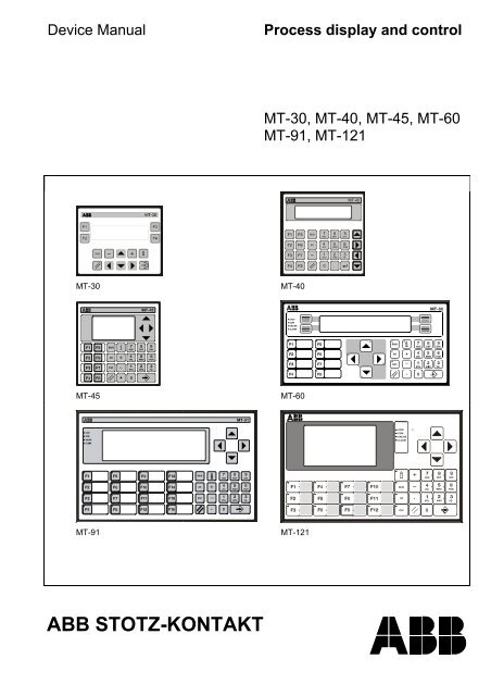
1 Product Overview1.1 Product range• Terminal MT-30 / MT-40 / MT-45 / MT-60 / MT-91 / MT-121• Programming lead• Connecting lead to the automation devices• Depending on the protocol driver, a data handling block, if required• Barcode wand if required (only MT-91 / MT-121)• Barcode scanner if required (only MT-91 / MT-121)E8Process display and control/ Device Manual/ Issue: 07.01
1.2 Overview machine terminals with text displayFunction/ Equipment MT-30 MT-40 MT-60Display type LCD VFD LCDNumber of lines 2 2 4Number of characters/lines 20 20 40Character height [mm] 5 5 5Type of keyboardMembrane keyboard with pressure point; Operating cycle > 1 MillionFunction keysFreely markable/ numberSoftkeysCursor keysAlphanumeric keysLED keysFunction keysCursor keys/ Movement keysCharacter setsLatin/ EuropeanCyrillic (capital letters)Greek (capital letters)Printer and programminginterface V.24Communications interface(galvanically isolated)TTYV.24RS485/RS4224--yesno8--yesyes8+4yes/84yesyes----84333yesyesyesyesyesnonononono yes yesyesno galvanic isolationOptionyesno galvanic isolationOptionyesOptionOptionMemory size [KByte] 128 32 128Number of texts 6000 1000 6000Type of memoryRAMEEPROMEPROMFlash-EPROMReal time clockBattery bufferedCapacitor buffered/ DataretentionFirmware modesSTS-ModesSPS-ModesSupply voltageNominal valueRange---yes----yes-yes-----yesyes---yesyes-yes/>4 T.24 VDC18,5...30,2 VDC according to EN 61131-2Current consumption [ca. mA] 300 250Ambient temperaturesStorageOperation-25°C...+70°C0°C...+50°CEnclosure frontAluminium plate with polyester foil; sealing; window; acrylic glassReal panel of enclosure Plastic Chromium plated steel plateProtection type, frontrearIP 54IP 20IP 54IP 20IP 65IP 20Relative humidityInterference resistanceInterference emissionEN-50082-2EN-50081-1EN 50082-2EN 50082-2EN 50082-2EN 50082-1DimensionsWidth [mm]Height [mm]Depth [mm]Installation depth [ca. mm]144112471071441446512528814470110Weight [kg] 0.4 0,45 1,1yesyesProcess display and control/ Device Manual/ Issue: 07.019E
1.3 Overview machine terminals with graphics displayFunction/ Equipment MT-45 MT-91 MT-121Display LCD VFD graphics display LCD graphics displayPixel 128x64 256x64 240x128Background illuminationdimming/ automaticallyLED- / -self-luminousyes / -CFLyes / yesContrast setting Trimmpoti - key combinationKeyboardsealed keypad (actuating cycle> 1 million)Keyboard illumination - yesFunction keysassignable / numbersoftkeysCursor keysAlphanumeric keys8yes / 8-yesyes16yes / 16-yesyes12yes / 12-yesyes8 (Stop, COM, Online, Alarm,Shift, Alt, Ctrl, Info )System LED´s - 4 (STOP, COM, ONLINE,ALARM)Function key LED ´s - 16 12/ with automatic dimmingNumber of binary inputs /- 8 (for floating contacts, pushbuttons, switches)electrical values (optional)30VDC / 5mANumber of binary outputs/- 4 /electrical valuesmax. 30 V, 500 mA, 30 W / 60VArelay output/- 1 alarm relayelectrical valuesmax. 30 V, 500 mA, 30 W/30VAReal time clock / data hold timeyes (capacitor buffered, maintenance free) / ≥ 4 daysPrinter and programmingyesinterface V.24Communication interfaceoptionally TTY, RS-232-C, RS-485/422Interface for barcode reader - RS-232, 5V supply for readerProgram memory capacity [kByte]4x128Number of protocol drivers3 (loaded from PC software)RAM / buffered [kByte]2x32 / yes (≥ 4 days)Protocol memory [kByte]12 / 200...900 messages approx.Configuration memory [kByte] 448Configuration memory typeFlash-EPROMNumber of process pictures3x1003x100Bitmap representation-yesBar graph/ pointer graph/-yesdifference bar graph functionNumber of texts / messages max. 5900Number of fault messages512 (bit control)Character sets3 (free definition)IBM code table 437 pre-defined in 3 sizesFonts (Number)lines, char./ line, height6x86x1212x2118x3138, 21, 4,5 mm5, 21, 5 mm3, 10, 10 mm2, 7, 15 mm38, 42, 8 mm5, 42, 12 mm3, 20, 21 mm2, 14, 31 mmSupply voltagenominal value24 V DC with reverse voltage protectionrange19,2...30,0 V DC acc. to DIN EN 611312Power consumption [mA],300 mA 400 mAtypically3-10, 40, 4 mm6, 20, 10 mm4, 13, 15 mmEnclosure front FR4 with polyester foil aluminium sheet with polyester foilEnclosure back plastic chrome steel sheetProtection type, frontrearIP 54IP 20IP 65IP 20Ambient temperature -20...+50 °C 0...+40 °CStorage temperature -25...+60 °CRelative Humidity80% at 25 °C, without condensationInterference resistance EN 50082-2Dimensions (wxhxd)Mounting cut-out (wxh)Wall thicknessInstallation depth144x144x65 mm138 (+1) x 138 (+1) mm≤ 40 mm125 mm312x192x79 mm300 (+/- 0,5) x 180 (+/- 0,5) mm< 8 mm120 mmWeight [kg] 0,6 2,0E10Process display and control/ Device Manual/ Issue: 07.01
1.4 Software concept of text terminalsBy means of the serial connection and the special adaptation to the respective PLC resp. host system, theoperating software PLC-Mode achieves a very high functionality. Additionally, this connection saves wiringexpenditure.The following mentioned functions are valid in principle for all devices. The differences are determined only by thevarious design of construction and display.1.4.1 Conveying, Moving, PositioningFunction and cursor keys are sent quickly and directly to the PLC resp. to the host.1.4.2 Displaying, parameterizing, dosing, regulatingSimple adjustment of the display and edit menus by internal recall via function key. In every menu amaximum of 15 variables, actual values as well as nominal values, can be programmed very simply.For this the following display formats are available:– signed decimal (16 bit)– unsigned decimal (16 bit)– decimal as double word (32 bit)– fixed point display– hexadecimal– bit display– ASCII (max. 20 characters)– indirect text (text variables)The reading of variables and data conversion is automatically made in the corresponding PLCformat.1.4.3 Monitoring and controlFault bit processingFault 1Fault 240PLCAddresscontrol word+515 data wordsresp. registersPLC-Mode deviceBasis address fault bit (BS)Fault 1 - text BSFault 2 - text BS+1...Fault 240 - text BS+239PresentationFault headFault message 1Fault message 2Fault message 3...Fault message 31PresentationNew value First value PriorityThe terminals contain a high-functional fault bit processing with record function. 32 from 240/ 512 faults can beprocessed simultaneously. The faults can be displayed as a new value, first value or priority.Process display and control/ Device Manual/ Issue: 07.0111E
1.4.4 RecordingThe devices contain a record memory / history with time and date. The messages / faults are filed with all information(variables etc.).1.4.5 PrintingDevices with printer interfaces can print– instant messages– display contents– fault messages– the history1.4.6 Menu structureFunction and Soft KeysF-Key xF-Key yCursorCursorMenu 1Text nText n+1...Menu 2Text mText m+1...Softkey vSoftkey wCursorCursorMenu 1Text nText n+1...Menu 1Text nText n+1...Complex menu structures can be produced very simply. The function keys can each be assigned to one menu.There can be any number of texts per menu. The B-keys ( screen keys, softkeys at MT-60, MT-82A) can beassigned differently in every menu, to recall other menus or to carry out control functions.E12Process display and control/ Device Manual/ Issue: 07.01
1.4.6.1 Dynamic menu branchingMenu structure(Text 10)→Hall A →Hall B →Hall C(Text 200)Hall A→Pump →Motor →Valve(Text 300)Hall B→Pump →Motor →Valve(Text 400)Hall C→Pump →Motor →Valve(Text 210)Hall A Pump→On →Off(Text 220)Hall A Motor→On→Off(Text 230)Hall A Valve→On→Off(Text 232)Hall AValve On(Text 234)Hall AValve OffBy means of this function, tree-structured architectures can be created without large-scale PLC programming.The several elements are shown to the user with an arrow in the first position. With the keys "cursor left" and"cursor right", the cursor can be placed from arrow to arrow. He selects by operating the key and thedisplay changes to the next menu text.1.4.7 LanguagesNot only system texts, but also operating texts created by the user can be switched to another language.Every device contains a set of three languages. The default combination is German, English and French: refer tothe appendix "Languages and fonts" for other sets.Process display and control/ Device Manual/ Issue: 07.0113E
1.5 Software concept of graphic terminalsDisplay• pixel graphics for background (except MT-45!)• semi-graphic character set (fully configurable) in 3 character sizes• display protection with parametric assignment for display OFF time by operator and PLCCommunication• transparent active control through the terminal via controller specific protocol, cutting complexities of programmingfor communication.• implementation of several protocols within one device (switching at system configuration level).Delivering, moving, positioningFunction and cursor key offer direct and fast input into the PLC or process control systemDisplay, parameters, metering, regulating• simple and comfortable generation of display and parameter menus• 25 formatted process variables per process display for selection♦ numeric data formats with input limitation and linear scaling♦ bar graph, cursor graph (linked directly to the process variables)♦ differential bar graph with dynamic tool centre point♦ all scale factors from PLC• automatic data readout and conversion at the terminal• direct input via barcode (scanner or pen).Monitoring and control• fault processing per single bit, rendered as new or first value or priority with internal confirmation to enter field inPLC• convenient protocol functions in the internal protocol memory, history with up to 900 entries.Menu structures• simple generation of menu structures (parameter masks, tree structures) without PLC program• direct activation of internal functions through function keys.E14Process display and control/ Device Manual/ Issue: 07.01
Programming• generating process images, fault texts etc. through PC programs in SAA standard• generating or changing characters. This provides for the use of any type of character (such as Cyrillic, Greek,Japanese…)• importing pixel graphics in bitmap format.Firmware downloadDownload of the complete firmware with• protocol drivers• system languages• character sets.1.6 Accessories1.6.1 Programming leadstype: VB 30cable length: 5 mconnector:PC side 9 pin sub-D socketMT-50 / MT-120 side 25 pin sub-D plug1.6.2 Connection leads to automation devicesThe information about the connection leads to the PLC systems can be found in Chapter "Installation to the PLC".1.6.3 Function modules, additional librariesAs a rule, specific function modules or program libraries will not be required for communication with the device.Where they are required for specific protocols or interfaces, you can find their parameters set out in Chapter"Installation to the PLC".1.6.4 Barcode reader unitsA barcode reader can be plugged directly into the MT if required. The reader should have the following specifications:• integral barcode decoder• 5V power supply / max. 250mA• RS-232-C or RS-232-TTL interface• no preamble (header)• (0Dh, 13d) as postamble (trailer)• ASCII coded characters (20h...7Fh)• interface parameter7 data biteven parity1 stop bit9600 baudProcess display and control/ Device Manual/ Issue: 07.0115E
The following barcode readers have been tested with the devices and can be supplied:• Handheld barcode laser scannerWelch Allyn Pistolgrip reader 5700/A-02,connecting lead 42204747-01, (9 pin sub-D connector, male)light source:670nm red lightinterface type:RS-232-TTLprogramming:- RS-232 interface- 9600 baud, 7 data bits, parity bit even, 1 stop bit- preamble, none- postamble, CR (Carriage Return)- other settings, Welch Allyn standard settingsterminal assignment: 2 - TxD, 5 - GND, 9 - +5Vpower consumption:115mA for 5V power supply• Barcode-CCD-ScannerWelch Allyn Touchreader3400/B-122,connecting lead: 42204747-01, (9 pin sub-D connector, male)light source:670nm red lightinterface type:RS-232-TTLprogramming:- RS-232 interface- 9600 baud, 7 data bits, parity bit even, 1 stop bit- preamble, none- postamble, CR (Carriage Return)- other settings, Welch Allyn standard settingsterminal assignment: 2 - TxD, 5 - GND, 9 - +5Vpower consumption:115mA for 5V power supply• Barcode wandWelch Allyn Wandconnecting lead:light source:interface type:programming:terminal assignment:power consumption:6180/A-21QJX, (X = connector code)specify when ordering, 9 pin sub-D connector (male)660nm, red lightRS-232-TTL- 9600 baud, 7 data bits, parity even, 1 stop bit- preamble, STX- postamble, CR (Carriage Return)- other settings, Welch Allyn standard settings2 - TxD - blue, 5 - GND - white, 9 - +5V - red22mA for 5V power supply• Barcode slot readerWelch Allyn Slot Reader 6480/A-A48X22, (X = connector code)connecting lead:specify when ordering, 9 pin sub-D connector (male)light source:660nm, red lightinterface type:RS-232-Cprogramming:- 9600 baud, 7 data bits, parity even, 1 stop bit- preamble, none- postamble, CR (Carriage Return)- other settings, Welch Allyn standard settings terminal assignment:2 - TxD - yellow, 5 - GND - white, 9 - +5V - redpower consumption:75mA for 5V power supplyE16Process display and control/ Device Manual/ Issue: 07.01
2 Communication2.1 Protocol Driver CS31The communication with the ABB Procontic CS31/ AC31 (07 KR 91, 07 KT 92, 07 KT 93, 07 KT 94) is made via theserial interface COM 1.The memory access is made to any word and double word flags.Attention: For performance reason you should use the Modbus protocol via COM2 (07 KT 94).2.2 Protocol Driver T200 - HI-ProtocolThe MT can be couples to the ABB Procontic T200 with the HI-Protocol.The communication protocol is the HI-Protocol and furthermore as communication module data words in the WRrangeresp. the MW-range with ABB Procontic T200. These data words are read and written cyclically with the taskcodes 40h and 42h. The MT is procedure master, the PLC slave.The coupling is possible to:• CPU Interface (RS-232 with CTS)• ABB KP60 (RS-232 or RS-422; see mode switch info in the system description of ABB Procontic T200)2.3 Protocol Driver Modbus RTUTested connections:• AC31 with 07KP93• T200 with 07MK62• AC31 COM2• AC41/ 51 COM1There are two firmware versions for controls with Modbus RTU Protocol:• SPS-Mode Modbus RTU Master• SPS-Mode Modbus RTU Slave2.3.1 Modbus RTU MasterFor a simplification of the ABB AC31 addressing via the Modbus Protocol a special routine was developed, thismake a direct parameterizing of the variables possible.2.3.2 Modbus RTU SlaveThe "Modbus RTU" described in the "Modicon Modbus Protocol Reference Guide" serves as communicationprotocol. The interface parameters are adjustable. Access to the memory of a special type in the PLC is made withreference numbers:BXXXXFour position addressMemory type: 4 - Memory registere.g. Flag register 1 = 40001Detailed information can be found in Chapter "Function description PLC Mode/General"Process display and control/ Device Manual/ Issue: 07.0117E
2.3.3 Format for Modbus RTUGenerally the message format of the Modbus RTU is:T1 T2 T3 Address Function Date Checksum T1 T2 T3with T1...T3:Break periods between two telegrams. The receiver waits for a new address after a breakperiod of at least three and a half character transfer periods.Address:Remark:Function:Substation number of the communication partner.The address is set via the substation number of the PLC Mode device.The following are used by the PLC Mode device from a great number of function of the Modbusprotocol. The type of function code is influenced by the address entry.CodeFunction01 Read spools and discrete output flags. This function code is used if the address isprefixed with a "0". e.g. for reading and display of the first 16 flags #00001XXXX02 Reading of discrete inputs by a "1" prefixe.g. reading of the first 16 input flags #10001XXXX03 Reading of one of more output registersPrefixed by a "4". e.g. reading of the first register and decimal output#40001UUUUU04 Reading of an input register prefixed by a "3"05 Setting of a marker06 Writing of a single register15 Writing of a number of flags is the same as Code 116 Writing of a number of register is the same as Code 317 Detecting of the AEG PLC / diagnosisAttention: Memory types "1" (discrete input flag) and "3" (input register) can only be read; i.e. they mustnot be used in the "Basic definitions" or "variable editing"Check sum: Fault detection operates with CRC-16 and the polynome x 16 +x 15 +x 2 +1E18Process display and control/ Device Manual/ Issue: 07.01
2.4 Protocol Driver ARCNETARCNET: Attached Resource Computer NetworkBecause of its speed, calculable reaction times and its flexible data packet size, ARCNET is applicable in thesensor/ actor area as well as in the process or cell bus level. Bus, star and tree topologies can be realized.Token Passing ProcedureToken is passed independently of the net topology to the node of the respective next higher ID. Each station gets astation ID between 1 and 255 (each number only one time). Data packet size flexible up to 508 byte; then tokenmust be passed. Because of the flexibility, the net data rate is up to 71%. Protocol safety is not a problem becauseof checksums in the data packet (16 Bit CRC) and handshake protocol between sender and receiver.Multimaster operationNew participants can always be signed on or cancelled. If token is lost then the network is reconfigured. Timebehaviour is deterministic. Applicable transmission media are coaxial cables, twisted pair or optical fibrewaveguides. Networks can be expanded by HUB´s and transmission media can be changed. With Coaxial cables2,5 Mbps max. 16 km can be achieved and with twisted pair 6 km. Standards: ATA / ANSI 878.1, 878.2 and 878.32.4.1 Terminal interfacing via ARCNETTo achieve simple and effective data transmission to visualisation systems a protocol according to Modbus RTUwas developed. In the PLC program, beside the ARCNET blocks AINIT, AREC, ASEND, ASEND+, and APOLL theconnecting element 5F_ARC (for 07KT92/93) or 5F_ARC94 (for 07KT94 ) is used. 5F_ARC and 5F_ARC94 arefunctionally identical.These connection element call via the block CALLC a C subroutine which interprets the received data.The protocol works according to a master/ slave principle, the terminal is always the master and the PLC is alwaysthe slave. Data that is sent and received is configured in the terminal. A standard program is always used in thePLC. Several masters can be connected to one PLC; in that case, the PLC program must be expanded withseveral 5F_ARC or 5F_ARC94. Additionally to this protocol a communication between the PLCs according to theblock descriptions ASEND, ASEND+ and AREC can be realized.The coupling can be made to all operating devices with ARCNET interface.Process display and control/ Device Manual/ Issue: 07.0119E
3 Mounting Instructions and Installation3.1 Guidelines for Engineering / InstallationThe following guidelines provide instructions for the safe integration of the product into larger systems or installations.• Regulations for safety and accident prevention must be observed for each application.• Devices may only be used when they are fitted and the enclosure is closed.• Provision must be made to enable that the products can be isolated from power at any time (for fixed installationsvia an all pole mains isolator switch or fuse); protective conductors must be grounded.• Supply voltages must comply with the specifications in the manual and tolerances must be observed.Caution:• Malfunctions may occur if the specified tolerances are either not met or exceeded!• Provisions must be made to ensure that the installation / the system is not triggered into dangerous orundefined states by power failures or interruptions.• Emergency stopping devices must remain effective in all operational situations and states.• Connection leads (particularly data transfer leads) must be provided and installed in such a way that theinstallation / system cannot be affected by capacitance or inductive interference. Measures must betaken so that undefined states cannot develop, even when leads are interrupted.• The products must be installed in such a way that unintentional activation of functions is avoided.• Wherever malfunctions may cause damage to equipment or to staff, additional external safety fail-safeswitching must be provided (such as limit switches, mechanical latches etc.).E20Process display and control/ Device Manual/ Issue: 07.01
3.2 Interference suppression / installation guidelinesPlease note carefully !The terminals are electronic devices which incorporate the latest technology. Their robust mechanical constructionas well the electronic components are designed for industrial use.Even so, it is necessary to observe certain basic measures when setting up such devices in industrial installationsto safeguard failure free operation:Interference voltages which can reach the device via supply and signal leads as well as electrostatic electricitythrough contact should be discharged through the ground terminal (such as the screw terminal at the rear of thehousing).This ground terminal must have a low resistance copper lead, kept as short as possible, either linked with the earthcontinuity conductor (yellow/green) or included in the equipotential grounding (permissible diameter of the cable :2,5mm² - 4mm² for terminal connectors, 10mm² for bolt type screw connectors, ·≥ 10mm² for equipotentialgrounding).If this is not observed, the high level of resistance to interference or damage which is a feature of the device maybe rendered ineffective.When the location for fitting the device is selected, it is important to maximise distance from areas of electromagneticfield disturbance. This is particularly important where frequency converters are in use.Under certain circumstances, it may be advisable to screen ‘disturbancy emitters’ with metal plates.Inductors in the vicinity (such as contactor, relay and magnetic valve coils) must be switched through fused links(such as RC links), particularly if they are connected to the same power supply.Power supplies and data leads should be routed to steer clear of interference.This may be achieved, for example, by not running them parallel to high power cables which give rise to interference.The following note applies to all devices which have been tested according to EN 50081-2; see the appendedDeclaration of EG-Conformity.Warning !This is a class A equipment. This equipment may cause radio interference in residential areas. In this case the usercan be required to take appropriate measures and he will have to pay the costs for them.Process display and control/ Device Manual/ Issue: 07.0121E
3.2.1 Shielding cables / leadsShielding measures are important to reduce (dampen) magnetic, electric or electromagnetic interference fields.Types of shielding :For shielded leads, you should use only cables or leads with braided shielding (recommended coverage > 80%).Foil shielding should not be used, since foil does not dampen all frequencies equally.In addition, foil shielding may be damaged through tension and compression during fitting and operation whichwould reduce effectiveness.Single sided or double sided connection of shielding:As a rule, optimal damping of all incoming interference frequencies can only be achieved by using the doublesided connection method!Using the single sided connection method may be more favourable if:− there is a potential difference and an equipotential bonding conductor cannot be installed− only foil shielded leads are available.Shielding connectors:A low impedance connection to ground or to equipotential grounding is of special importance, to ensure that theinterference current from the shielded cable does not itself carry a source of interference.When using sub-D connectors, you should always bring the shielding into contact with the metallic or metallisedconnector casing of the sub-D connector.Do not, under any circumstances, solder the shielding to pin 1 of the connector strip.There are a few exceptions to this rule, see guidelines for connection.Some controllers have connector casings which are not optimally connected to ground. In such a case, it would bean advantage to isolate the screening at the sub-D connector of the PLC and link it with the shortest possible lead(0.75mm 2 ...1.5mm 2 ) directly to the protective ground conductor.For stationary use, we recommend that the shielded cable is fully insulated and in contact with the PE bar orequipotential bonding.The screening end at the interface will not be fixed in this case!When screening is treated in this way, make sure cable clips which provide good contact all around the shieldbraiding are used.E22Process display and control/ Device Manual/ Issue: 07.01
Examples for connections:1. Shielding of serial coupling to controller in double sided contact.With additional equipotential bonding lead (10mm² required).PLCMTEquipotential leadCentralpointgroundingAs a rule, double sided contact will result in the optimal damping of all connected interference frequencies.The power supply to the machine terminal may also be through the supply of the PLC.2. Shielding the serial coupling to controller through single sided contact.Without equipotential bonding lead.PLCMTPotential differenceCentral groundingpointIn this case, the equipotential flow would be across the shielding, if the shield connection was double sided.This must definitely be avoided, since the resulting interference impulses could be fed into the devices via thedata input lead.Where shielding is single sided, the shield connection must be made on the side of lowest impedance as nearas possible to the central grounding (connection A in the example).Before commissioning, it is necessary to check the installation instructions specified by the manufacturer for safeoperation. They should be reconciled with the recommendations here.Screen connection with MT-30:Via 6.3 mm flat connector (not included in delivery).Process display and control/ Device Manual/ Issue: 07.0123E
3.3 Instructions for Mounting and InstallationRemove the terminal from the packaging. Items supplied are:− the MT− mounting elements• two for MT-40 and MT-45• four for MT-30• six for MT-60• eight for MT-91 and MT-120− this manual where applicableFitting can be directly into− cabinet doors or− operating panels.Selection of fitting position according to:− optimal height for operator− good lighting, so that the display is easy to read− suitable ventilation to be used in case of high ambient temperatures.− Avoid mounting in the immediate vicinity of switchgear or power converters.Prepare an opening with the following dimensions:Device Width Height Fitting depth Thickness/materialMT-30 138 +1 mm 106 + 1 mm 105 mm approx. max. 18 mmMT-40, MT-45 138 +1 mm 138 + 1 mm 125 mm approx. up to 40 mmMT-60283 ± 0.5 mm 139 ± 0.5 mm 110 mm approx. max. 18 mmConst. variation IMT-60283 ± 0.5 mm 79 + 0.5 mm 110 mm approx. max. 18 mmConst. variation II+ 3 holes(see diagram)MT-91 300 mm 180 mm 130 mm approx. max. 10 mmMT-121 300 ± 0.5 mm 180 ± 0.5 mm 120 mm approx. max. 8 mmExchange the labelling strip before the installation:The labelling stripes are to be changed at the rear of the device.• Pull out paper-tapes carefully with a tweezers. Do not press into the slot with a sharp tool because the front foilwill be damaged!• Inscribe the paper-tapes• Carefully insert again (at an angle of approx. 45 degrees):• in doing this, do not apply any pressure on the front panel• angling the corners simplifies insertionIf you produce new stripes, these must correspond in size to the original stripes (see appendix, "Labelling strips").They may not protrude over the rubber seal.E24Process display and control/ Device Manual/ Issue: 07.01
Fit the device using the mounting elements:− Fix the clamps at even distances in the gaps of the casing.Optimal spacing:• MT-30, MT-40, MT-45 one mounting element per side• MT-60, MT-91, MT-121 three mounting elements to the upper and lower sidesas well as one mounting element to each of the sidesthemselves.− Finger tighten the screws.− Check the position of the display, and take special care to check the correct seat of the sealing rubber.− Now tighten the clamping screws with a torque of 60N/cm.Caution:IP 65 (or IP 54 for MT-40 and MT-45) will be achieved by• quality installation and fitting• use of a flat and smooth mounting surface (after the clamping screws have been tightened)• the specified torque setting.Process display and control/ Device Manual/ Issue: 07.0125E
3.3.1 Mounting Diagram MT-60Construction variation ISide viewMounting cut-outConstruction variation IISide viewMounting cut-outE26Process display and control/ Device Manual/ Issue: 07.01
3.3.2 Mounting Diagram MT-303.3.3 Mounting Diagram MT-40, MT-45max. 40mm144138+1138+1ca. 65mm144mit Bu-Stecker ca. 125mmDimensions of opening for installation in mmProcess display and control/ Device Manual/ Issue: 07.0127E
3.3.4 Mounting Diagram MT-91Dimensions of opening for installation in mm3.3.5 Mounting Diagram MT-121Dimensions of opening for installation in mmE28Process display and control/ Device Manual/ Issue: 07.01
3.4 Overview o f connection assignmentsBack wall MT-30Back wall MT-40Process display and control/ Device Manual/ Issue: 07.0129E
Back wall MT-60Back wall MT-91 / MT-121E30Process display and control/ Device Manual/ Issue: 07.01
Back wall MT-91 / MT-121 ARCNETProcess display and control/ Device Manual/ Issue: 07.0131E
Connections:Identification Significance FunctionX1 1 + 24 V supply energy supply to terminal3 GND supplyX2 2 RXD printer andsetting 3 TXD programming interfaceRS-232-C 5 *CTS7 GND14 programming15 V.2416 GND programming17 GND V.24X2 9 RxD- communication TTYsetting 11 lin1TTY 12 lout113 TxD-22 lin223 lout224 RxD+25 TxD+X3 1 output 1a relay output2 output 1b (only MT-60, MT-91, MT-121)X4 2 TxD communication RS-232variant 3 RxDRS-232-C 5 GND7 *CTS8 *RTSX4 9 TxD A communication RS-422/485variant 3 TxD BRS-422/485 6 RxD A4 RxD BX5 1 input 1 (max. 30V dc) pushbuttons or switches2 input 2 (max. 30V dc) (only MT-91, MT-121, optional)3 input 3 (max. 30V dc)4 input 4 (max. 30V dc)5 input 5 (max. 30V dc)6 input 6 (max. 30V dc)7 input 7 (max. 30V dc)8 input 8 (max. 30V dc)10 / 22 output 1 (max. 60V dc)11 / 23 output 2 (max. 60V dc)12 / 24 output 3 (max. 60V dc)13 / 25 output 4 (max. 60V dc)14 0 V (input 1-8)X6 2 RxD barcode reader unit3 TxD (only MT-91, MT-121)5 GND7 *RTS8 *CTS9 + 5 V Signals marked "*" are "0" active.Connections which are not listed are left unconnected.E32Process display and control/ Device Manual/ Issue: 07.01
3.5 Fieldbus interface of variant MT-30/ MT-45/ MT-91/ MT-121 ARCNET3.5.1 Cable typeCable: RG 62DC resistance:1.12 Ohm / 100 mCharacteristic impedance: 93 Ohm / 1 MHzMaximum cable attenuation: 1.8 dB / 100 m3.5.2 Fieldbus plugConnection:BNC plug with 75 Ohm characteristic impedanceorBNC connecting element (T-form) with 75 Ohm characteristic impedance3.5.3 ConnectionConnection at the end of the cableTerminatingresistor93 OhmConnecting element75 OhmBNC connection75 OhmRG 62Coaxial cablecharacteristic impedance93 OhmX14BNC socket75 OhmTerminalPicture: fieldbus connection to the terminal.Terminal is at the end of the cable.Process display and control/ Device Manual/ Issue: 07.0133E
Connection between the ends of the cableBNC connection75 OhmConnecting element75 OhmBNC connection75 OhmRG 62RG 62Coaxial cablecharacteristicimpedance 93 OhmCoaxial cablecharacteristicimpedance 93 OhmX14BNC socket75 OhmTerminalPicture: fieldbus connection to the terminal..The terminal is between the ends of the cable.E34Process display and control/ Device Manual/ Issue: 07.01
3.5.4 Cable length and number of participantsThis information applies to coaxial cable RG 62The transmitter output signal is 9dB higher than the signal required by the receiver.The connection of each further terminal (node) causes a loss 0.43dB.The cable RG 62 weakens the signal by 0.6dB per 30m at 5MHz.Requirement : usage of less than 19 participants on one cable.Number ofparticipantsLoss by participant Remainingsignal powerMaximumcable length2 0.43 dB 8.57 dB 435 m3 0.86 dB 8.14 dB 413 m4 1.29 dB 7.71 dB 391 m5 1.72 dB 7.28 dB 370 m6 2.15 dB 6.85 dB 348 m7 2.58 dB 6.42 dB 326 m8 3.01 dB 5.99 dB 304 m9 3.44 dB 5.56 dB 282 m10 3.87 dB 5.13 dB 260 m11 4.30 dB 4.70 dB 238 m12 4.73 dB 4.27 dB 217 m13 5.16 dB 3.84 dB 195 m14 5.59 dB 3.41 dB 173 m15 6.02 dB 2.98 dB 151 m16 6.45 dB 2.55 dB 130 m17 6.88 dB 2.12 dB 108 m18 7.31 dB 1.69 dB 86 m19 7.74 dB 1.26 dB 64 mProcess display and control/ Device Manual/ Issue: 07.0135E
3.5.5 Technical data of the ARCNET interface cardARCNET interface cardTransmission medium Coaxial cable, RG 62,Characteristic impedance 93 OhmConnectionsBNC socket, 75 Ohm for connection of a coaxial cableFunction indication1 diagnosis LED´sController COM 20020clock frequency 20 MHzInterface driverHCY9088AR by SMSCor A60152 by MITNode impedance≤1.2 kΩNode distance≥ 1mOperating element8 pole DIP switchfor setting the station address (Node-ID)Supply voltage +5Vtype 350 mAmax. 550 mAAmbient temperature0..50°CE36Process display and control/ Device Manual/ Issue: 07.01
3.6 Printer connectionWith communication interface RS-232 only for devices with optional interface V.24 on X4.In this case, communication interface is X4!3.7 Connecting a barcode readerA barcode reader may be connected directly to a MT-91/ MT-121 . The following specifications are required for areader:• integrated barcode decoder• 5V power supply / max. 250mA• RS-232-C or RS-232- TTL interface• no preamble or header label• (0Dh, 13d) as preamble or trailer• ASCII code characters (20h...7Fh)• interface parameter7 data bitseven parity1 stop bit9600 baudProcess display and control/ Device Manual/ Issue: 07.0137E
3.7.1 PIN assignment for barcode interface (socket X6)X6View PIN Signal name Description123456789-RxDTxDGND-*RTS*CTS+5Vinput leadoutput leaddata reference potentialrequest to send*clear to send*supply voltageSignals marked "*" are "0" active.3.7.2 Data transfer to the PLCTo input values through the barcode reader, the active (blinking) cursor must be on an input variable declared in Aformat. A screen form generated through PLCPlus consequently could look like this:batch number :personnel code :#EAAAAAAAAAAAA#EAAAAAAAAAAAAThe barcode input is saved from the address specified in the format (see A format). The address data (called and in the example) are given in the usual PLC specific format.If the barcode unit is used for entering a barcode of a length which matches the format, then• the code will be entered in both display and controller• the cursor will be set to the next editable variable (as happens after pressing the ENTER key)• in addition, the following bits are entered into the controller:"PLC address function key field"+00 Bit15Bit14Bit13Bit12Bit11Bit10Bit9Bit8Bit7Bit6Bit5Bit4Bit3Bit2Bit1Bit0meaningx x x x 1 x x x x x 1 x x x x x input through bar codereader unitIf the length of the code which has been entered deviates from that of the set format (is longer or shorter), thecursor will stop at the position of the last character which has been entered, to indicate this to the operator.However, if this value needs to be entered into the controller, the operator will have to confirm this by pressing theENTER key or scan the barcode again or else key the entry manually.3.8 Operation of alarm relay(not MT-40 and MT-45)The operation of the alarm relay can be set in the configuration menu:Alarm − the relay will be added in at the flashing of LED 4 (see fault bit processing)Keys − the relay is activated with the keys (function, cursor and display keys)E38Process display and control/ Device Manual/ Issue: 07.01
3.9 DIL switches S1The DIL switches serve to preset the display and have to be set before the system start.DIL switches 1...5: MT-40, MT-60 address adjustment (substation number)MT-45, MT-91, MT-121 no function┌───┬───┬───┬───┬───┬──────┐ ┌───┬───┬───┬───┬───┬──────┐│ 1 │ 2 │ 3 │ 4 │ 5 │ Adr.│ │ 1 │ 2 │ 3 │ 4 │ 5 │ Adr.│├───┼───┼───┼───┼───┼──────┤ ├───┼───┼───┼───┼───┼──────┤│OFF│OFF│OFF│OFF│OFF│ 1 │ │OFF│OFF│OFF│OFF│ON │ 17 │├───┼───┼───┼───┼───┼──────┤ ├───┼───┼───┼───┼───┼──────┤│ON │OFF│OFF│OFF│OFF│ 2 │ │ON │OFF│OFF│OFF│ON │ 18 │├───┼───┼───┼───┼───┼──────┤ ├───┼───┼───┼───┼───┼──────┤│OFF│ON │OFF│OFF│OFF│ 3 │ │OFF│ON │OFF│OFF│ON │ 19 │├───┼───┼───┼───┼───┼──────┤ ├───┼───┼───┼───┼───┼──────┤│ON │ON │OFF│OFF│OFF│ 4 │ │ON │ON │OFF│OFF│ON │ 20 │├───┼───┼───┼───┼───┼──────┤ ├───┼───┼───┼───┼───┼──────┤│OFF│OFF│ON │OFF│OFF│ 5 │ │OFF│OFF│ON │OFF│ON │ 21 │├───┼───┼───┼───┼───┼──────┤ ├───┼───┼───┼───┼───┼──────┤│ON │OFF│ON │OFF│OFF│ 6 │ │ON │OFF│ON │OFF│ON │ 22 │├───┼───┼───┼───┼───┼──────┤ ├───┼───┼───┼───┼───┼──────┤│OFF│ON │ON │OFF│OFF│ 7 │ │OFF│ON │ON │OFF│ON │ 23 │├───┼───┼───┼───┼───┼──────┤ ├───┼───┼───┼───┼───┼──────┤│ON │ON │ON │OFF│OFF│ 8 │ │ON │ON │ON │OFF│ON │ 24 │├───┼───┼───┼───┼───┼──────┤ ├───┼───┼───┼───┼───┼──────┤│OFF│OFF│OFF│ON │OFF│ 9 │ │OFF│OFF│OFF│ON │ON │ 25 │├───┼───┼───┼───┼───┼──────┤ ├───┼───┼───┼───┼───┼──────┤│ON │OFF│OFF│ON │OFF│ 10 │ │ON │OFF│OFF│ON │ON │ 26 │├───┼───┼───┼───┼───┼──────┤ ├───┼───┼───┼───┼───┼──────┤│OFF│ON │OFF│ON │OFF│ 11 │ │OFF│ON │OFF│ON │ON │ 27 │├───┼───┼───┼───┼───┼──────┤ ├───┼───┼───┼───┼───┼──────┤│ON │ON │OFF│ON │OFF│ 12 │ │ON │ON │OFF│ON │ON │ 28 │├───┼───┼───┼───┼───┼──────┤ ├───┼───┼───┼───┼───┼──────┤│OFF│OFF│ON │ON │OFF│ 13 │ │OFF│OFF│ON │ON │ON │ 29 │├───┼───┼───┼───┼───┼──────┤ ├───┼───┼───┼───┼───┼──────┤│ON │OFF│ON │ON │OFF│ 14 │ │ON │OFF│ON │ON │ON │ 30 │├───┼───┼───┼───┼───┼──────┤ ├───┼───┼───┼───┼───┼──────┤│OFF│ON │ON │ON │OFF│ 15 │ │OFF│ON │ON │ON │ON │ 31 │├───┼───┼───┼───┼───┼──────┤ ├───┼───┼───┼───┼───┼──────┤│ON │ON │ON │ON │OFF│ 16 │ │ON │ON │ON │ON │ON │ 32 │└───┴───┴───┴───┴───┴──────┘ └───┴───┴───┴───┴───┴──────┘┌───┬───┬─────────────────────┐┌───┬───┬─────────────────────┐│ 6 │ON │ Keyboard ││ 7 │ON │ Clear memory ││ ├───┼─────────────────────┤│ │ │ !Programming plug ││ │OFF│ no keyboard(KA80) │├───┼───┼─────────────────────┤│ ├───┼─────────────────────┤│ 8 │ON │ Keyboard test ││ │OFF│ Conf.menu disabled │└───┴───┴─────────────────────┘└───┴───┴─────────────────────┘The default setting is:┌───┬───┬───┬───┬───┬───┬───┬───┐│ 1 │ 2 │ 3 │ 4 │ 5 │ 6 │ 7 │ 8 │├───┼───┼───┼───┼───┼───┼───┼───┤│OFF│OFF│OFF│OFF│OFF│ON │OFF│OFF│└───┴───┴───┴───┴───┴───┴───┴───┘Process display and control/ Device Manual/ Issue: 07.0139E
4 Installation on the PLC4.1 Installation on AC31 active COM1Standard communication interface:V.24/ RS-232-CThe communication with the ABB Procontic AC31 (07 KR 91, 07 KT 92, 07 KT 93, 07 KT 94) and to T200 with 07KP 62 is made on the serial interface COM1 (COM2 with special software). The memory access is made to anydouble word flags.To connect the device with the ABB Procontic AC31, both devices must have the same interface parameters. Theinterface parameters are adjustable, the defaults are:9600 baud8 data bits1 stop bitnon parityInstallation on X2The connection cable VB-85 is supplied as an accessory.MTX225pole Sub-DAC31COM19pole Sub-DScreen connection onconnector caseRefer to chapter "Interference suppression / installation guidelines" with regard to the screening/ interferenceresistance.E40Process display and control/ Device Manual/ Issue: 07.01
Installation on X4The connection cable VB-86 is supplied as an accessory.MTX49pole Sub-DAC31COM19pole Sub-DScreen connection onconnector caseRefer to chapter "Interference suppression / installation guidelines" with regard to the screening/ interferenceresistance.Process display and control/ Device Manual/ Issue: 07.0141E
4.2 Installation on the T200Standard communication interface:V.24/ RS-232-CThe interface parameters are adjustable, the defaults are:19200 baud7 data bits1 stop biteven parityPlease note that the interface parameters and the device addresses of both devices must correspond.E42Process display and control/ Device Manual/ Issue: 07.01
Installation via V.24/RS-232With a communication processor ABB KP the CTS handshake is not necessary. When using a CPU interface theCTS handshake must be adjusted.Installation on X2The connection cable VB13 is supplied as an accessory.MTX225-pole Sub-DPLC15-pole Sub-DScreen connection onconnector caseRefer to chapter "Interference suppression / installation guidelines" with regard to the screening/ interferenceresistance.Process display and control/ Device Manual/ Issue: 07.0143E
Installation on X4The connection cable VB-43 is supplied as an accessory.MTX49-pole Sub-DPLC15-pole Sub-DScreen connectionon connector caseRefer to chapter "Interference suppression / installation guidelines" with regard to the screening/ interferenceresistance.Caution:With the physically last terminal in the bus, termination must be made with a termination resistor.S3 1 2ON ONE44Process display and control/ Device Manual/ Issue: 07.01
4.3 Connection to 07KP93 - AC31 with Modbus-RTUThe following interfacing possibilities exist:• Modbus RTU Master for 07 KT 94 and new systems with Modbus on COM2 or withMK 92• Modbus RTU Slave for MK 92 as master4.3.1 Modbus RTU MasterProVicomExicomVariablesFaults/ KeysAC 31KR 31AC 31KR 31AC 31KR 31Access from the MT is made as Modbus RTU Master to the multi-slave PLCsPerformance class Multislave Variables Faults Function keysText Yes Any PLC 1 PLC 1 PLCGraphic Yes Any PLC 2 PLCs 1 PLCNote:For key functions with graphic devices also the sending function can be used. With that keyscan be transferred into all slaves as values.Now it is also possible to operate variables in several AC31 / KP93 slaves.Following parameters are allowed:Format Telegram type Address AC31 Address section Modbus-Basic-addresshexMW Word flags Register (XXMWggg,kk), (MW00,00)...(MW255,15) 2000MD Double wordflagsKWWordconstants*KD Double wordconstants*RegisterRegisterRegister(MWggg,kk)(XXMDggg,kk),(MDggg,kk)(XXKWggg,kk),(KWggg,kk)(XXKDggg,kk).(KDgg,kk)M Binary flags Binary Data (XXMggg,kk),(Mggg,kk)* no write accessXX Station number 0...31ggg Group number 0...31kk Channel number 0...15(MD00,00)...(MD31,15) 4000(KW00,00)...(KW39,15) 3000(KD00,00)...(KD07,15) 5000(M00,00)...(M255,15) 2000If no station number was defined, those AC31 will be addressed, witch Modbus address correspond with thepreset station number of the terminal. (Text terminals with DIL, Graphic terminals with the configuration menu).Process display and control/ Device Manual/ Issue: 07.0145E
4.3.2 Modbus RTU SlaveAC 31MK 92RS-422/485MT MT MTThe MK 92 must be parameterized as master.• Communication interface: RS-232 with CTS• Notes:Programming expanse in PLC4.3.3 Installation overviewThe function block MOD_INIT initializes the MODBUS coupler and realizes the operating mode SLAVEMOD_INITFREICOMMSLVBAUDParameters:FREI BINÄR A, E, S, M, K Release of the block processingCOM WORT KW Interface identification (3 or 4)MSLV WORT KW 0 = Master, 1...254 Slave-AddressBAUD WORT KW Baudrate (1200, 2400, 4800, 9600)E46Process display and control/ Device Manual/ Issue: 07.01
4.3.4 Connection via V.24 on X2The connection cable VB-57 is supplied as an accessory.MTX225-pole Sub-D07KP93 - AC3115-pole Sub-DScreen connection onconnector caseRefer to chapter "Interference suppression / installation guidelines" with regard to the screening/ interferenceresistance.4.3.5 Connection via V.24 on X4The connection cable VB-58 is supplied as an accessory.MTX49-pole Sub-D07KP93 - AC3115-pole Sub-DScreen connection onconnector caseRefer to chapter "Interference suppression / installation guidelines" with regard to the screening/ interferenceresistance.Process display and control/ Device Manual/ Issue: 07.0147E
4.3.6 Connection via RS-485 on X2MTX225-pole Sub-D07KP93 - AC3115-pole Sub-DCable requirments:twisted pair andscreenedScreen connection onconnector caseRefer to chapter "Interference suppression / installation guidelines" with regard to the screening/ interferenceresistance.4.3.7 Connection via RS-485 on X4MTX49-pole Sub-D07KP93 - AC3115-pole Sub-DCable requirments:twisted pair andscreenedScreen connection onconnector caseRefer to chapter "Interference suppression / installation guidelines" with regard to the screening/ interferenceresistance.E48Process display and control/ Device Manual/ Issue: 07.01
4.3.8 Connection via RS-422 on X2MTX225-pole Sub-D07KP93 - AC3115-pole Sub-DCable requirments:twisted pair andscreenedScreen connection onconnector caseRefer to chapter "Interference suppression / installation guidelines" with regard to the screening/ interferenceresistance.Process display and control/ Device Manual/ Issue: 07.0149E
4.3.9 Connection via RS-422 on X4MTX49-pole Sub-D07KP93 - AC3115-pole Sub-DCable requirments:twisted pair andscreenedScreen connection onconnector caseRefer to chapter "Interference suppression / installation guidelines" with regard to the screening/ interferenceresistance.E50Process display and control/ Device Manual/ Issue: 07.01
4.4 Connection to AC 31 with Modbus-RTU4.4.1 Installation on X2Interface cable VB-85 can be supplied as an accessory.MTAC31X2COM225-pole Sub-D9-pole Sub-DScreen connection toconnector enclosureRefer to Device Manual, Chapter "Suppression measures /Installation guidelines" for screening and interferenceimmunity.Process display and control/ Device Manual/ Issue: 07.0151E
4.5 Connection to AC 41/ AC 51 with Modbus RTU4.5.1 Installation on X4MTX29pole Sub-DAC41/ AC51MINI-DIN 8poleScreen connection toconnector enclosureRefer to Device Manual, Chapter "Suppression measures /Installation guidelines" for screening and interferenceimmunity.4.5.2 Installation on X4MTX49pole Sub-DAC41/ AC51MINI-DIN 8poleScreen connection toconnector enclosureRefer to Device Manual, Chapter "Suppression measures /Installation guidelines" for screening and interferenceimmunity.Process display and control/ Device Manual/ Issue: 07.0153E
4.6 Connection 07MK62 - T200 with Modbus-RTU4.6.1 Connection via V.24 on X2MTX225-pole Sub-D07MK62 - T2009-pole Sub-DScreen connection onconnector caseRefer to chapter "Interference suppression / installation guidelines" with regard to the screening/ interferenceresistance.4.6.2 Connection via V.24 on X4MTX49-pole Sub-D07MK62 - T2009-pole Sub-DScreen connection onconnector caseRefer to chapter "Interference suppression / installation guidelines" with regard to the screening/ interferenceresistance.E54Process display and control/ Device Manual/ Issue: 07.01
4.7 Connection to KR / KT31 with Modbus-RTU4.7.1 Connection V.24 on X2MTX225-pole Sub-DKR / KT319-pole Sub-DScreen connection onconnector caseRefer to chapter "Interference suppression / installation guidelines" with regard to the screening/ interferenceresistance.4.7.2 Connection V.24 onMTX49-pole Sub-DKR / KT319-pole Sub-DScreen connection onconnector caseRefer to chapter "Interference suppression / installation guidelines" with regard to the screening/ interferenceresistance.Process display and control/ Device Manual/ Issue: 07.0155E
4.8 Installation on ABB AC 31 via ARCNETThe technical data of the ARCNET interface can be found in the chapter titled "Mounting instructions and installation/Fieldbus interface of variant MT-91/ MT-121 ARCNET"To connect the device to the ARCNET interface the following steps must be made:4.8.1 Setting the Node-ID/ station addressThe DIP switch S2 serves for the definition of the Node-ID (node resp. station number).The Node-ID has to be between 1 and 255 (with a Node-ID of 0, all DIP switches off, the ARCNET controller wouldneither receive nor send any token).DIP position:S21 2 3 4 5 6 7 8 Node-IDOn Off Off Off Off Off Off Off 1Off On Off Off Off Off Off Off 2On On Off Off Off Off Off Off 3...........................On Off On On On On On On 253Off On On On On On On On 254On On On On On On On On 2554.8.2 Optical indication, LED tokenThe lighting up of this LED token signals that a token has been received from another station. The bus connectionis OK.E56Process display and control/ Device Manual/ Issue: 07.01
4.8.3 Block 5F_ARC resp. 5F_ARC945F_ARCFREIT_I1T_O1ERROP0FREI Bit ReleaseT_I1 Word 1. effective data flag receiveT_O1 Word 1. effective data flag sendERR Word ErrorOP0 1. Operand in operand memory (KW00,00)The telegrams consist of an ARCNET head (CP,DIN,JOB_NR) and the MODBUS RTU telegram which may notexceed the maximum of 125 words. For sending and receiving in the PLC, a space of 125 flag words for each(sending and receiving) must be kept free. All telegrams are send with the DIN identification 5F and the effectivedata size (AREC/ASEND) 125 (maximum size). As Job-no. always the ARCNET address of the respectiveparticipant is used. This Job-No. is written in the ASEND resp. ASEND+ blocks and in the AREC.Example: If the master (terminal) has the ARCNET address of 1 and the PLC has the ARCNET address 2 then inthe PLC program in AREC Jobnumber = 1 and in ASEND Jobnumber = 1.4.8.4 Structure of the ARCNET telegramSender Receiver CP DIN MASTERLowMASTERHighCounter Counter Slave FCT Effectivedata03 5F xx 00 aa aa yy zz0 1 2 3 4 5 6 7 8 9 10-256Counter / aaaa :Master / xx :Slave / yy :FCT / zz :Counter, refreshed by the master and written the slave to avoid telegram doubling - thiscounter is not used for the checksum. The counter is the 1. word in the received telegram.This word must be assigned to the 1. word in the response telegramARCNET address of master == JOB-No in AREC/ASEND blockARCNET address of slave, starting from here begins the MODBUS-RTU telegram (seechapter format of Modbus RTU )function codeProcess display and control/ Device Manual/ Issue: 07.0157E
4.8.5 Program example for interfacing a terminal to an ABB PLCInitialising ARCNET+--------+¦AINIT ¦M 255,15-------¦0/1 DONE+-----M 250,00KW 10,00-------¦TO ERR+-----M 250,01¦ NODE+-----MW 250,00¦ STAT+-----MW 250,01¦ DIAG+-----MW 250,02¦ TOS+-----M 250,02¦ TOND+-----MW 250,03¦ TOJN+-----MW 250,04¦ LEV+-----MW 250,05¦ RECO+-----M 250,03+--------+; KW 10,00 = 200 (Equivalent to 200msec)+--------+¦VRZ ¦K 00,01--------¦FREI ¦M 250,02-------¦ZV ¦K 00,00--------¦ZR ¦KW 01,01-------¦DIFF ¦K 00,00--------¦S ¦KW 01,00-------¦ZW ¦K 00,00--------¦R Z+-----MW 130,00+--------+; K 00,00 = 0; K 00,01 = 1; KW 01,00 = 0; KW 01,01 = 1+--------+¦AWT ¦M 250,02-------¦0/1 ¦MW 130,01------¦0 ¦MW 250,03------¦1 +-----MW 130,01+--------+;Sending data packets from buffer to ARCNET+--------+¦APOLL ¦¦ ¦+--------+E58Process display and control/ Device Manual/ Issue: 07.01
ArcNet reading procedure of the PLC;Reading the data packets from ARCNET terminal;(MT -Terminal (Nr.3) -> ABB-SPS Nr.1);N0= ArcNet-Adr. Terminal;#J0=ArcNet-Adr. Terminal+--------+¦AREC ¦# +00001--------------------------------¦#JOB ¦+--------+ ¦ UJOB+-----M 250,04¦ZUDKW ¦ ¦ ¦# +00003-------¦# V+---------------¦N0 ¦+--------+ ¦ ¦#H 005F---------------------------------¦#D0 ¦# +00003--------------------------------¦#J0 ¦# +00125--------------------------------¦#L0 ¦MW 220,00-------------------------------¦MW0 JR0+-----M 250,05+--------+;Declaration of the terminal's own ARCNET address (DIP switch);Decoding the received telegram+--------+ +--------+¦ZUDKW ¦ ¦WAND ¦# +00001-------¦# V+-----¦ ¦ +--------++--------+ ¦ ¦ ¦ ¦=? ¦MW 220,01-----------------+---¦ +-----¦Z1=? ¦¦ +--------+ ¦ Q+-----M 251,14+------------------¦Z2 ¦+--------+;Assigning serial number to send+--------+¦=W ¦MW 220,00------¦ +-----MW 228,00+--------+Process display and control/ Device Manual/ Issue: 07.0159E
5 Setting up5.1 Brief initiationThis section provides the support for starting up the device in a simple way. The setup which is described below isonly suitable for test purposes; for a permanent installation, it is important to follow the guidelines in Chapter"Mounting instructions and installation".For the first test, you will require− 1 MT− 1 lead VB-30 for downloading system and texts via PC− 1 lead for coupling the device to the PLC (according to interface and type of coupling)− 1 floppy disk "Configuration Software SPSPlus (PLCPlus) (Installation Disk 1)Additionally for graphic devices− 1 floppy disk "Drivers" (Installation Disk 2)In addition, a power supply of 24V dc / min. 0,5 A has to be provided.5.1.1 PC ProgramInstall the program on the hard drive of your PC.− Place the floppy disk into drive A: or B:.− Change the drive.− Enter "INSTALL".The installation is now controlled by the menu:− Enter drive and path.− From the components, select the demo configuration of your protocol driver.− Select the interface. Make sure that there is no mouse driver installed for this interface.− Select the further settings according to your system.− Start your program with the input SPSPlus (PLCPlus) .The PC is now ready for programming.5.1.2 MT− Join a 24V power supply to the MT (connector X1)MT-30, MT-40, MT-60:− The device starts with a self test. The coupling mode and firmware version is then indicated− After successful memory test the display indicates"No communication for the control" .Usually a demo configuration is loaded into the device before delivery, so that the device does not have to beconfigured first.MT-45, MT-91, MT-121:− The device will start with a self test, which indicates the version of the initial program loader (IPL) of the MT.− If no system has been loaded, it will have to be loaded first via PLCPlus.− Join PC and MT via the VB-30 lead.− Program the system:− via the configuration menu (subheading "Programming texts/system?")− directly when starting up the device (see Chapter "Setting up / Startup keys").Process display and control/ Device Manual/ Issue: 07.0161E
5.2 System download of MT-30Info:All terminals are loaded before delivery with the ordered valid system, so that in the normal case the systemdownload into the target device is not necessary.If you still want to download the system, please proceed as follows1. Switch off the voltage from the MT-30.2. Remove the back wall cover of the MT-30.3. Plug jumper 1 (on the left side of the board- see picture) to position 2-3.4. Switch on the voltage for the MT-30The device changes automatically into the system programming.Attention:After the start and during the download in the MT-30 display only the upper line is represented withinverted pixels.So you will not see any changes of state of the MT-30!5. Start the download from SPSPlusWIN and answer the question: "Would you like to download system too" withyes.The message appears"Prepare device for the firmware download and press OK".Confirm this message not until the point 1-4 are performed.6. After successful system download the message appears in SPSPlusWIN:"Prepare device for configuration download and press OK."Info: Always after system download, you must also load the configuration into the terminal.7. Switch off the voltage from the MT-30 again.8. Plug jumper 1 again to position 1-2.9. Switch on the voltage from the MT-30 again.10. The terminal starts up again regularly.11. Change the terminal into the text programming mode.12. Start the transfer "without system"13. After successful download the device is ready for interfacing to the PLC.Process display and control/ Device Manual/ Issue: 07.0163E
5.3 Starting-up and self test of MT-30, MT-40 and MT-60The device has extensive self tests and error diagnoses; e.g. text memory test and RAM test; which are carried outwhen the system is started. This starting-up phase is reported by a text display. In the following, the masks of theMT-60 are shown for coupling to the PLC; those of other devices are correspondingly designed*** MT - 60 ***SELF - TEST* MT-40 *SELF - TEST* MT-30 *SELF - TESTWith a faultless run the device switches to the information mask. The mask informs you about the type of deviceand the selected operation mode.Type of device*** MT - 60 ***FLASH V 2.70 NR:01Memory type RAM, EPROM, Software version Device addressEEPROM or Flash-EEPROMAfter approx. one second, this information is replaced by the basic mask.5.4 Error messages after the startIf the following message appears on the display:!!! ERROR IN TEXT MEMORY !!!PLEASE REPROGRAMthe device has found a faulty initialized text memory and must be reprogrammed.The message!!! ERROR IN HISTORY BUFFER !!!HISTORY BUFFER DELETEDrefers to a structural error in the history. Due to data security the history buffer was reinitialized therefore informationwas lost.Due to the fact that the MT-40 does not have a buffered RAM, this message always appears after switching on.E64Process display and control/ Device Manual/ Issue: 07.01
5.5 Configuration during operation of MT-30, MT-40 and MT-60Reference:Please take the definitions of the keys used here (e.g.) from the chapter "Operations/Keyboard definitions".• Recall of the menu by simultaneously operating keys and .• The configuration of the devices is menu controlled.• The preselected configuration points are marked by a flashing cursor.• Cursor selection is made by MT-series equipment:− Set the left and right cursor keys below the required adjustment.• With you acknowledge the selected adjustment.• With the old adjustment remains active.For editing certain values, e.g. password, the alphanumeric block is used.5.5.1 Country codeIn the following menu the country code can be adjusted. Please take the tables of the country code from theappendix of this manual. In addition to the pure code switch the messages are displayed in the correspondinglanguage.COUNTRY CODEGO ON DEUTSCH ENGLISH FRANCAIS5.5.2 PasswortThe entry into the configuration menu is protected by a password and the password mask appears :ENTER THE PASSWORT PLEASE : 00000EXIT + - OKAt this point the correct password must be entered.Process display and control/ Device Manual/ Issue: 07.0165E
Reset passwordThe calculated reset of the password can be initialized by simultaneous operation of + when restartingthe device. As a default, the character string '00000' is loaded.If the password entry was correct the password can be changed:GO ONCHANGE PASSWORD ?YESIf the entered password does not correspond to the current password the following mask is put out! ! ! PASSWORD NOT VALID ! ! !GO ONand a password reentry is demanded.5.5.3 Setting the clock(does not apply for MT-30 and MT-40)After input of the valid password the following mask appears:NEW VALUE INPUT 00.00.00 00:00:00EXIT + - OKCurrent time and date are displayed and can be changed.5.5.4 ProgrammingIf there is a programming plug on connection X2 the following mask appears:NOPROGRAM TEXT ?YESIf you have chosen "YES", the following mask appears:EXITTEXT PROGRAMMINGNow the device can be programmed by means of a PC and the configuration software PLCPLUS.Attention: In the PLCPLUS the "Standard" interface format must be set to 9600baud, 8, 1, even parity.E66Process display and control/ Device Manual/ Issue: 07.01
5.5.5 Brightness control of the displayThe brightness of MT-40 from serial number 62102 onwards can now be very easily set. The presetting for the startis made in the following mask:DISPLAY BRIGHTNESSGO ON 60% 100%DISPLAY BRIGHTNESSGO ON 20% 40%Attention:As soon as the dim values have been recalled from the control then these will be valid!5.5.6 Printer configurationPrinter configuration is selected in the following mask:CONFIGURE PRINTER ?NOYESThe handshake for the printer is activated after "YES" has been selected..PRINTER WITH RTS/CTS HANDSHAKEGO ON NO YESAfter this the number of characters can be set for each print width.CHARACTERS PER PRINTED LINEGO ON 20 40 80Selection of page formatting is adjustable in the following mask:PRINTING WITH PAGE FORMATTING ?GO ON NO YESIf page formatting is selected a page feed and a header text is made after 55 lines. This function can be switchedoff when using endless paper and for the control of printer switching.If printer GDM183 is used then "YES" must be selected in the following mask.PRINTER GDM 183GO ON NO YESFor technical reasons the data format of the printer must correspond to the general serial configuration.Process display and control/ Device Manual/ Issue: 07.0167E
5.5.7 Configuration of the serial interfaceThe parameters of the serial interface you find in the Protocol Driver Manual, Chapter "Installation on the PLC"The configuration of the serial interface can be initiated in the following mask:CONFIGURE SERIAL INTERFACE?NOYESParity adjustmentAfter the selecting "yes" the serial configuration is requested and the following mask appears:SETTING PARITYGO ON NONE EVEN ODDAdjustment of the data bits per wordNow select the number of the data bits per wordNUMBER OF DATABITSGO ON 7 BIT 8 BITAdjustment of the stop bitsNUMBER OF STOP BITSGO ON 1 BIT 2 BITIf the following mask now appears!!! DATA FORMAT NOT VALID !!!ENTER NEW CONFIGURATIONthen you have selected a configuration which is not valid.Cause: With a data format of 8 data bit and an even parity only 1 stop bit is admitted.Please operate any key and reconfigure.E68Process display and control/ Device Manual/ Issue: 07.01
Adjustment of the baud rateIn the next mask the baud rate can be configured :NOSETTING BAUD RATE ?YESAfter the selecting "YES" the following masks offer the configurable baud rates:SETTING BAUD RATEGO ON 600 BD 1200 BD 2400 BDBAUD RATEGO ON 4800 BD 9600 BD 19200 BD5.5.8 Relay controlRELAY CONTROL WITHGO ON ALARM KEYSIn this mask the operation of the relay can be parameterized.Alarm - The relay is connected when LED 4 (see fault bit processing) is flashing.Keys - The relay operates in synchronism to key activities (function -, cursor - andscreen keys)5.5.9 Driver specific settingsThe specific settings of the protocol driver are described in Chapter "Installation on the PLC".Process display and control/ Device Manual/ Issue: 07.0169E
5.5.10 Text offset (language offset)By switching the language an offset is added simultaneously to all text recalls in the memory. The offset for the firstlanguage is always 0; the offsets can given for 2 and 3.Both text offsets are given in the following mask (in this case: Offset 1)ENTER TEXT OFFSET 1 : 0000EXIT + - OKWhen setting the text offset to 0, the devices operate compatible to the older versions.5.5.11 Save configuration (only for devices with flash EPROM)SAVE CONFIGURATION IN FLASH EEPROM?NOYESThis menu offers the possibility to save the configuration (country code, serial interface etc.) in the flash EPROM.The configuration data is filed into the RAM. If an error is detected in the RAM when starting (e.g. after a longvoltage failure due to capacitor discharge) then it is automatically refreshed by the flash EPROM.E70Process display and control/ Device Manual/ Issue: 07.01
5.6 Starting-up and self test of MT-45, MT-91 and MT-121The device offers a comprehensive range of routines for self testing and error diagnosis, which are activated atstartup.After all protocol drivers and system configurations have been loaded to the terminal, the system will go through anumber of phases.5.6.1 Messages during startup phase 1 (boot program)SAE MT-XXX MAIN BOOTmessage from boot system000: SYSTEM IS BOOTING. PLEASE WAIT...010: TESTING CODE BANKS...after start of system testing program code banks001: OK.OK message when error free08X: JUMP IN DRIVER XOperational error:011: ERROR! NO CODE BANKS. LOAD SYSTEM.012: WAITING FOR SYSTEM PROGRAMMING...error message: no driver protocolsterminal waiting f. system download (9600, 8, 1, e)Operational error:(*1) during system test:021: ERROR! NO SYSTEM. LOAD SYSTEM.012: WAITING FOR SYSTEM PROGRAMMING...error message: no driver protocolsterminal waiting f. system download (9600, 8, 1, e)(*2) during system configuration testing:024: BUFFER FAILURE. GETTING FLASH DATA. error message: no valid system configuration.automatic loading of flash parameters025: FLASH UNVALID.GETTING DEFAULT DATA. default values will be loaded if errors are found in flash dataProcess display and control/ Device Manual/ Issue: 07.0171E
5.6.2 Messages during starting phase 2 (driver start)APP. VERSION: 4.XXDRIVER VERSION: 1.XX022: TESTING SYSTEM CONFIGURATION...001: OK.024:TESTING TEST MEMORY001: OK.040: TEST BARCODE CONTROLLER001: OK.reading application versionreading driver versionerrors from configuration testing indicated by (*3)errors from text memory testing indicated by (*4)errors from barcode testing indicated by (*5)(*3) for configuration error:023: ERROR! GET DEFAULT CONFIGURATION error in text or configuration memory(*4) for text memory error:025: ERROR IN TEXTMEMORY error in text or configuration memory(*5) for barcode decoder error :103: ERROR! BARCODE CONTROLLER! error in text or configuration memoryE72Process display and control/ Device Manual/ Issue: 07.01
5.6.3 Basic MaskAfter error-free self testing, the device will display the basic mask, i.e. process picture 0 (if this is programmed) orthe following default initial display.PLC MODE dd.mm.yy hh:mm:ssMT-XXX-BC5.6.4 Error messages from protocol driver*** error 300 ***communications errorThe protocol driver cannot achieve communication with the PLC.Possible causes:• damage to the communication lead• faulty interface parameters*** error 301 ***address does not existAn address for a variable or within the general specifications does not exist in the PLC.*** error 304 ***configuration errorThe general specifications are faulty.Possible causes:• invalid address• address spacing at fault.Process display and control/ Device Manual/ Issue: 07.0173E
5.7 Configuration during operation - MT-45, MT-91 and MT-1215.7.1 General5.7.1.1 Key definitionsThe following key descriptions are used for the configuration:Key Description Comment escape key cursor up cursor down carriage return / enter5.7.1.2 Setting the configuration• Call up the menu by simultaneously pressing keys and .• Device configuration is menu-guided .• Pre-selected configuration items are marked by an inverse cursor bar.• The devices offer selection by cursor control:− Move cursor bar over the setting you require by using keys and .• Confirm the setting by using the key .• If you wish to retain the previous setting, use the key.E74Process display and control/ Device Manual/ Issue: 07.01
5.7.2 General settings5.7.2.1 Language options / contrastConf-Version: x.xxSelect Language / Change ContrastLanguage 1Language 2Language 3 - Select - Exit-Set Contrast - OKLanguage selection with cursor keys and confirmation with .Contrast settings:• key "+"darker• key "-"lighter• key "."medium.5.7.2.2 Password (hidden entry)Please enter the password***** - Exit - OK• enter password using the alphanumeric keys.• Confirm with .Process display and control/ Device Manual/ Issue: 07.0175E
5.7.2.3 Change password?Change password?YesNo - Select . - Exit - OKIf you want to change the password, select "Yes" and then enter new password.Pointer:when you start the device, you can reset the password to 00000 by pressing the and keys simultaneously.5.7.2.4 Date / TimePlease enter time & date00.00.00 00:00:00 - Exit - OK• Enter date as in "dd.mm.yy" (dd = day, mm = month, yy = year).• Enter time in the European 24 hour format "hh:mm:ss" (hh = hours, mm = minutes, ss = seconds).E76Process display and control/ Device Manual/ Issue: 07.01
5.7.2.5 Programming texts / systemDownload configuration / system?Burn-in boot system?yes ( 9600 / 8 / 1 / E)yes (19200 / 8 / 1 / E)yes (57600 / 8 / 1 / E)No-Select. - Exit - OK• Burn-in boot system:Used to update the boot system of the MT-50 / MT-91 / MT-121Caution!Only use this option for extreme emergencies only!Never switch off the 24V power supply while burning a new boot system, since this will render the devicenonoperational so that it will have to be returned to the manufacturer.• Yes (...)Download with the selected parameters.Programming:• the system (character sets, languages, driver protocols) or• the configuration (process images, texts etc.)• for different speeds• 9600 baud - for slow PCs and serial interface without "FIFO"• 19200 baud - for medium PCs and serial interface without "FIFO modules"• 57600 baud - for fast PCs and serial interface with "FIFO modules".If selecting "Yes":Terminal ready for programmingbaud rate as selected8 data bits, 1 stop bit, even parityProcess display and control/ Device Manual/ Issue: 07.0177E
5.7.2.6 Interface parameter printer (COM 3)only for devices with COM3 option.Change printer?YesNo - Select . - Exit - OKPrinter data bit / stop bit7 data bit, 1 stop7 data bit, 2 stop8 data bit, 1 stop8 data bit, 2 stop - Select . - Exit - OKPrinter parityno parityeven parityodd parity - Select . - Exit - OKPrinter baudrate2400 baud4800 baud9600 baud19200 baud57600 baud - Select . - Exit - OKE78Process display and control/ Device Manual/ Issue: 07.01
Printer flow controlnoneXON/XOFF (software) - Select . - Exit - OKCharacters per line20 characters40 characters80 characters - Select . - Exit - OKProcess display and control/ Device Manual/ Issue: 07.0179E
5.7.2.7 Interface parameter COM1Caution:Please remember that the setting of the interface COM1 must match that of the PLC. You can find theinstructions in Chapter "Installation on the PLC".Change COM1?YesNo - Select . - Exit - OKCOM1 databit / stopbit7 databit, 1 stopbit7 databit, 2 stopbit8 databit, 1 stopbit8 databit, 2 stopbit * - Select . - Exit - OK*) the setting "8 data bit, 2 stop bit " requires the selection of "no parity".COM1 parityno parityeven parityodd parity - Select . - Exit - OKCOM1 Baudrate2400 Baud4800 Baud9600 Baud19200 Baud57600 Baud - Select . - Exit - OKE80Process display and control/ Device Manual/ Issue: 07.01
5.7.2.8 Substation numberCaution:The substation number is used to identify an device during programming.Please enter the substation number01 - Exit - OK5.7.2.9 Background lightingfor MT-121 onlyDisplay backlightalways onswitch off after 5 minutesswitch off after 10 minutes - Select . - Exit - OKHere the operator can decide to have the background illumination on at all times, or have it switched off automaticallyafter 5 or 10 minutes, without key commands.5.7.2.10 Relay control (MT-91/ MT-121 only)Relay control viaunreceipted dynamical faultkeyboard - Select . - Exit - OKThis offers a choice for fault relay control. The setting "unreceipted dynamical fault" means that the relay willalways be activated if the source of a dynamic error has not been confirmed. The setting "keyboard" means thatthe relay will always be activated when a function key or cursor key is pressed.Process display and control/ Device Manual/ Issue: 07.0181E
5.7.2.11 Protocol driverCaution:The selected protocol driver must match the configuration. Please pay attention to the instructions inChapter 6.1!Protocol driversdriver 1driver 2driver 3 - select . - Exit - OK5.7.2.12 Showing fault textsYou can set the number of lines per fault text this mask.Showing fault texts1 line per text2 line per text3 line per text4 line per text - select . - Exit - OK5.7.2.13 Showing historyIn this mask you can set the number of lines per history text.Showing history1 line per text2 lines per text3 lines per text4 lines per text - select . - Exit - OKE82Process display and control/ Device Manual/ Issue: 07.01
5.7.2.14 Handling the fault listThe following menu can be used to handle the variables in dynamic faults.Handling the fault liststatic variablesdynamic variablesselection via PLC - Select- . - Exit - OK5.7.3 Protocol specific settingsProtocol specific settings are described in Chapter "Installation on the PLC".5.7.4 Test menuCaution:The tests which follow must be run by qualified service personnel. This is for testing the terminal as anindividual component.Go on with test menu?YesNo - Select . - Exit - OKProcess display and control/ Device Manual/ Issue: 07.0183E
5.7.4.1 Keyboard testTest keyboard?YesNo - Select . - Exit - OKIf selecting "yes":Keyboard test (exit with ESC):• keys will be displayed on screen when pressed.5.7.4.2 LED testTest LED?YesNo - Select . - Exit - OKIf selecting "yes":LED test (exit with ESC):• The system LEDs "COM", "ONLINE" and "ALARM" will light up.• Pressing the "INFO" key will light up the corresponding LED.• Pressing a function key will light up the corresponding LED.E84Process display and control/ Device Manual/ Issue: 07.01
5.7.4.3 Display testTest display?YesNo - Select . - Exit - OKIf selecting "yes":• Display will be inverted after key is pressed. Finish the test by pressing .5.7.4.4 Barcode test(only for devices with optional barcode decoder)Test barcode?YesNo - Select . - Exit - OKIf selecting "yes":Barcode scanner unit activatedExit test with • A correctly read bar code will be indicated on screen.Process display and control/ Device Manual/ Issue: 07.0185E
5.7.4.5 Input test (MT-91 / 121 only)Test inputs?YesNo - Select . - Exit - OKIf selecting "yes":Set and clear inputsInput 1 2 3 4 5 6 7 8on .off ¦ ¦ ¦ ¦ ¦ ¦ ¦ ¦exit test with • indicates input states5.7.4.6 Testing relay output ( MT-91, MT-121 only)Test relay?YesNo - Select . - Exit - OKIf selecting "Yes":Test relayswitch relay onswitch relay offExit test with • The relay can be switched on or off.E86Process display and control/ Device Manual/ Issue: 07.01
5.7.4.7 Test COM1Test COM1?YesNo - Select . - Exit - OKIf selecting "yes":Test COM1 with loop back plugsent : .received : .Exit test with A loop-back connector needs to be plugged in for running the COM test.5.7.4.8 Show system textsShow system texts?YesNo - Select . - Exit - OKIf selecting "yes":View system texts / - scrolling+ / - : change languagetext number : .Exit test with • output of all system textsProcess display and control/ Device Manual/ Issue: 07.0187E
5.7.4.9 Show bitmaps (not MT-45)Show bitmap?YesNo - Select . - Exit - OKIf selecting "yes":The first existing bitmap is displayed first, the following / previous maps are scrolled by using . Afterthe last bitmap, the display reads:Last bitmap!5.7.4.10 Repeating the testsRepeat system test?YesNo - Select . - Exit - OK• Repetition of the system test as described above.5.7.4.11 Saving the system settingsCaution:System settings which have been altered must be saved in Flash-EPROM, otherwise they will be lost aftera cold start.Store conf.-settings into Flash-EPROM?YesNo - Select . - Exit - OKIf selecting "yes":Configuration is being saved in Flash-EPROM. Please waitE88Process display and control/ Device Manual/ Issue: 07.01
5.8 Startup keys of MT-45, MT-91, MT-121Certain keys can be activated for special functions during startup.Keydesignation+effectsetting back passwords, history and systemconfiguration to "00000".7 direct branch into system configuration9 direct branch into system programming with57600/8/1/E6 direct branch into system programming with19200/8/1/E3 direct branch into system programming with9600/8/1/EProcess display and control/ Device Manual/ Issue: 07.0189E
6 Function description of PLC-Mode6.1 GeneralThe PLC-Mode was developed for terminals to realise a direct and fast communication with the PLC.MTLEDEDisplayFunction keysHistory memoryText memoryFunction key memoryCursorA.-Num-BlockItalic: address areas in SPSPlus WINThe coupling data area is structured as follows:1. PLC address: 'function key field'Address in which the terminal deposits the function key bits.2. PLC address of control wordsAddress in which the PLC writes the control words.3. Address of message data wordsAddress in which the PLC writes the message registers.4. Area of variables:Master:area is unlimited (marker and register)Modbus-Slave: registers behind time register, number 400.90PLCPLC address 'function key field'/Keyboard range− PASS bit− Cursor key bits− Function key bits (max. 80)Acknowledgements(for Modbus-Slave only)− dynamic control word− message register− history register− time registerPLC address of control words/LED-Bit range + Fault messagerange− 3*16 LED-Bits− Fault bit− Control bitAddress of message data words/Message register− Message register− History register− Text number register− Time registerVariables− Marker and Registerfor slave behind time registerPLC address acknowledgement/Acknowledge range (onlyGraphic)− fault bit acknowledgementThe addresses of each address block are placed in increasing sequence. The following pages show tablescontaining offset addresses. On the following pages, offset addresses are specified in tables; the executiveaddress is calculated from the basic address + offset address. In the tables the functions are briefly explained andcompleted with examples.Process display and control/ Device Manual/ Issue: 07.01
6.1.1 Address declaration for CS316.1.1.1 Address declaration in PLCPlus-GThe addresses of the memory areas must be declared as follows:double word flagggkk(MDggg,kk)gg Group number 0...31kk Channel number 0...15The example program belongs to the standard program package of PLCPlus. The following basic addressesare valid for the demo (see "Basic definitions"):PLC address 'function key field': (MD000,01)Number of function key bits: 64PLC address of control words:Address of message data words:PLC address acknowledgement:(MD001,04)(MD002,09)(MD006,04)Number of fault words: 15Entry of control code: #Text number of fault bits: 500System file:[SYSTEM\CS3.SDT]Text offset language 1: 2000Text offset language 2: 4000"PLC address acknowledgement" and "Number of fault words" apply only for graphic terminalsThe following double word flags must be reserved for the individual addresses:Address function key field7 MDAddress of control words text 20 MDgraphic (5 + number of fault words) MD *Address of message data words10 MD* The length of the fault bits is adjustable in the system menuNote:For the transfer of control words and function keys, the value 8000h (-32768) is absolutely necessary. This value,however, is forbidden in the AC31 for word flags. Therefore data exchange happens in the lower 16 bits (Bit 0... Bit15) of the double word flags except variable format 'D'. Here the whole double word flag is used.Process display and control/ Device Manual/ Issue: 07.0191E
Cycle time:Number of fault words Number of faults Time ms without variable Time ms with one variable15 240 680 85010 160 560 74005 80 460 63002 32 380 550If the inputs IN1...IN8 should be transmitted, the number of function key bits has to be 64.6.1.1.2 Address declaration in SPSPlus WINIn the Generic driver must be declared:Declaration of theprotocol and the protocolstringThe addresses of the memory areas must be declared as follows:Declaration ofthe MD groupnumberDeclaration ofthe MD channelnumberDeclaration of thebit number resp. bitcount depending onthe variable typeThese declarationsare not relevant forCS31 protocol driverE92Process display and control/ Device Manual/ Issue: 07.01
6.1.2 Address declaration for T200 in PLCPlus-GThe addresses of the memory areas must be declared as follows:Address declaration(MWXXX,YY)(LUMWXXX,YY)RangeDeclaration of the word flagsDeclaration of the word flags with Link number and UnitnumberLUXXXYY= Link number= Unit number= Group number= Channel number0...20...F (hexadecimal)0...1270...15For the text terminals, addressing with L, U is possible only from Version 2.79; previous versions can address onlythe directly connected station. Only 10 characters are at the disposal! All configuration addresses must have the same values L, U.Reaction of the terminals:If L, U are not declared in the address then Link number and Unit number are set via the substation number of thedevice (DIL resp. configuration menu):UST-Nr = 1 L, U are F, F (connected station)2 1, 0 Station 03 1, 1 14 1, 2 2etc.In this case, only one line can be addressed.If LU are declared in the address with 00 then the connected station is addressed.Examples:UST-Nr (MW000,01) (00MW000,01) (17MW000,01)1 LU = FFLU = FFLU = 17connected station connected station2 LU = 10 LU = FFLU = 17connected station3 LU = 11 LU = FFLU = 17connected station4 LU = 12 LU = FFconnected stationLU = 17Process display and control/ Device Manual/ Issue: 07.0193E
The following basic addresses are valid for the demo (see "Basic definitions"):PLC address 'function key field': (MW000,01)Number of function key bits: 64PLC address of control words:Address of message data words:PLC address acknowledgement:(MW001,04)(MW002,09)(MW006,04)Number of fault words: 15Entry of control code: #Text number of fault bits: 500System file:[SYSTEM\HIT.SDT]Text offset language 1: 1000Text offset language 2: 2000"PLC address acknowledgement" and "Number of fault words" apply only for graphic terminalsThe following word flags must be reserved for the individual addresses:Address function key field7 MWAddress of control words text 20 MWgraphic (5 + number of fault words) MW *Address of message data words10 MW* The length of the fault bits is adjustable in the system menuCycle time:Number of fault words Number of faults Time ms without variables Time ms with one variable15 240 680 85010 160 560 74005 80 460 63002 32 380 550If the inputs IN1...IN8 should be transmitted, the number of function key bits has to be 64.E94Process display and control/ Device Manual/ Issue: 07.01
6.1.3 Address declaration for Modbus6.1.3.1 GeneralThere are two options for controls using Modbus RTU Protocol:• Modbus RTU Master• Modbus RTU SlaveTerminal operating as master− point-to-point coupling− read and write in any memory area− active reading of all data− automatic conversion of variablesTerminal operating as slave− Networking of up to 31 terminals to one master− automatic conversion of variables− Terminal reacts to send and fetch telegramsNecessary master operations− cyclical request of function keys and acknowledgements (time-out = 10s)If the timeout is overstepped the error message appears:"No function key data request"Telegram structure:• Function code 03 "Read one or more output registers"• address for exampleModicon 40001Telegram address 0• number of registers = 16If the area of time registers is not needed then a request of 10 registers is sufficient− spontaneous or cyclical sending of control words, message register and variables• Function code 16• address for exampleModicon 40020telegram address 19• number of registers = 23 + 6 (clock) + variables− spontaneous request of modified variables• Function code 03 "Read one or more output registers "• address for exampleModicon 40050 (Variable 1)telegram address 49• number of registers = 1Process display and control/ Device Manual/ Issue: 07.0195E
6.1.3.2 Address declaration for Modbus-Slave in PLCPlus-GRange for Master for Slave othersOutput register yes 4XXXX W(XXXX)Example register 1 40001 W(0001)with XXXX = 0001...9999The following basic addresses are valid for the demo (see "Basic definitions"):PLC address 'function key field': 40001Number of function key bits: 64PLC address of control words: 40020Address of message data words: 40040PLC address acknowledgement: 40100Number of fault words: 15Entry of control code: #Text number of fault bits: 500System file:[SYSTEM\MOS.SDT]Text offset language 1: 2000Text offset language 2: 4000"PLC address acknowledgement" and "Number of fault words" are valid only for graphic terminalsThe following register must be reserved for the following addressesAddress 'function key field'16 registersAddress of control words Graphic (5 + number of fault words) registersText 20 registersAddress of message data wordsup to 400 variable registersIf the inputs IN1...IN8 should be transmitted, the number of function key bits has to be 64.E96Process display and control/ Device Manual/ Issue: 07.01
6.1.4 Address declaration Modbus-Master in PLCPlus-GFor a simplification of the ABB AC31 addressing via the Modbus Protocol a special routine was developed, thismake a direct parameterizing of the variables possible.Now it is also possible to operate variables in several AC31 / KP93 slaves.Pay attention to the following notes:• MT and Slaves must have a RS-485 or RS 422 interface• the Slaves must have different Modbus addresses [1...31]• the preset of the Modbus address has to be done via the station number of the terminal (Text terminals withDIL, Graphic terminals with configuration menu).• the address sections of the Basic definitions can always be assigned for one slave, that means that all Faultbits are coming from one slave etc...• the variables within the texts can come from any terminal• Choose the general PLC-Mode in PLCPlusFollowing parameters are allowed:Format Telegram type Address AC31 Address section Modbus-BasicaddresshexMW Word flags Register (XXMWggg,kk), (MW00,00)...(MW255,15) 2000(MWggg,kk)MD Double word Register (XXMDggg,kk), (MD00,00)...(MD31,15) 4000flags(MDggg,kk)KW WordRegister (XXKWggg,kk), (KW00.00)...(KW39,15) 3000constants(KWggg,kk)KD Double word Register (XXKDggg,kk), (KD00,00)...(KD07,15) 5000constants(KDgg,kk)M Binary flags Binary Data (XXMggg,kk), (M00,00)...(M255,15) 2000(Mggg,kk)* no write accessXX Station number 0...31ggg Group number 0...255 (length depends on the format)kk Channel number 0...15If no station number was defined, those AC31 will be addressed, witch Modbus address corresponds with thepreset station number of the terminal. (Text terminals with DIL, Graphic terminals with the configuration menu).Example for Basic definitions:PLC address 'function key field:PLC address of control words:Address of message data words:(3MW00,00)(3MW00,10)(3MW01,14)Examples for text addressing:(3MW10,02)UUUU (4M10,02)B (MW10,02)UUUUSlave 3 Slave 4 Slave of DIL-/ configuration addressNote for Modbus Master:Communication is faster if a space of (5 + number of fault words) registers between "PLC address of controlwords" and "Address of message data words" is selected.Process display and control/ Device Manual/ Issue: 07.0197E
Special features for graphic terminals:The address areas for fault bits ("PLC address of control words"+5) and acknowledgement can be divided to twostations:mm/nnMWgg,kkmm/nnMDgg,kkmm 1. station number 0...31nn 2. station number 0...31gg group number 0...31kk channel number 0...15"PLC address of control words" and "PLC address acknowledgement" are independent from each other; it dependson the system design whether they are both devices or not.The effect of such an address division is• the first half of the fault bits is read from station mm• the second half of the fault bits is read from station nn• the first half of the acknowledgement is read from station mm• the second half of the acknowledgement is read from station nnExample:PLC address of control words: 3/4MW10,0PLC address acknowledgement: 12/15MW5,0Number of fault words 31In this case the allocation is:Station 3 Station 4LEDsMW1,0...MW10,2 (3 words)Control words MW10,3...MW10,4 (2 words)Fault bits MW10,5...MW11,3 (15 words) MW 11,4...MW12,3 (16 words)Station 12 Station 15Acknowledgement MW5,0...MW5,14 (15 words) MW5,15...MW6,14 (16 words) The usual parenthesises of the AC31 addressing can now be cancelled for graphic terminals with protocoldriver Modbus-Master; splitted address area must be declared without parenthesisesExamples for valid addresses:11/12MW05,011/12MD5,102/3MW13,00 Only 10 characters are at the disposal!E98Process display and control/ Device Manual/ Issue: 07.01
6.1.5 Address declaration Modbus-Master in SPSPlus WINAddress specification is made with format and address (group, channel).The following parameters are enabled:FormatTelegram AC31 address area Modbus basictypeaddress hexAW** Output words Registers AW 0,0...AW 7,15 1000EW** Input words* Registers EW 0,0...EW 7,15 0000MW Word flags Registers MW 0,0...MW 255,15 2000MD Double word Registers MD 0,0...MD 31,15 4000flagsKW Word Constants* Registers KW 0,0...KW 39,15 3000KD Double word Registers KD 0,0...KD 7,15 5000constants*A** Outputs Binary data A 0,0...A 63,15 1000E** Input* Binary data E 0,0...E 63,15 0000M Binary flags Binary data M 0,0...M 255,15 2000* No write access** Address declaration only in SPSPlus WINThe station parameters look as follows:The process connections look as follows:Process display and control/ Device Manual/ Issue: 07.0199E
The following register must be reserved for the following addressesKeyboard field5 MWLED-Bit field Text 15 MWGraphic (number of fault words) MWFault message field (LED-Bit field + 5) 5 MWMessage register10 MWIn SPSPlus WIN, LED-Bit range and fault message range must be declared separately. However, they are to be handled as one block and must have a distance of 5 MW in the PLC memory.E100Process display and control/ Device Manual/ Issue: 07.01
6.2 Description of Functions / OverviewThe following questions and answers should provide an overview of the PLC-Mode functions. A detailed specificationof each function is given in the reference section.6.2.1 Shifting, Moving, PositioningHow are keys transferred to the PLC??When pressed, all function keys and special keys are passed into the function key field as a key bit, which is thenreset again when the key is released. The alphanumeric keys are used for editing the required value, and are nottransferred ("Key Functions" reference section and "Keyboard Operation").How can control functions be implemented?The function keys and the soft keys can contain control functions, i.e. can write set values to the PLC in a desiredlocation within the memory area for variables ("Programming Functions/ Screen Keys" section).Process display and control/ Device Manual/ Issue: 07.01101E
6.2.2 Display FunctionsWhat is a Text?The terminals have a text memory arranged according to text numbers. All texts (apart from the function key texts)are managed here, irrespective of their function. This enables parts of text to be combined easily. The function keytexts are managed separately according to their key assignment.What is a Process picture?The respective base text numbers 0...99 of a language are termed process pictures.Text number0Text memory99100Text offset language 1Text offset + 99Text offset language 2Text offset + 99What Types of text exist?There are:−−Menu texts, which manage several display pages(see chapter "Message texts")Control texts, which manage one display page (see chapter "Message texts")− Fault texts, which manage important faults and messages (see chapters "Message texts" and "Fault BitProcessing")−−Help texts, which provide extra information for each display (see chapter "Help Texts").Function key texts, which trigger actions when a key is pressed (see chapter "Programming Function Keys")E102Process display and control/ Device Manual/ Issue: 07.01
How can a picture or text display be called up?There are various options for calling up texts:− using a function key ("Programming Function Keys" section)− using soft keys ("Soft Key Programming" section)− calling up a text from the PLC user programme using a text number ("Text Register" reference section)− calling up several texts at once with fault bit processing ("Fault Bit Processing" section)− using the info/help key ("Help Texts" section)− using the dynamic menu branching procedureHow can Actual Values be Displayed, and Nominal Values Edited?In each text the number of actual values which can be inserted, and the number of nominal values which can bemodified by the user, equals 25 in total. When the text is called up, the values are read automatically from thespecified address, and displayed in the correct format. If the variable can be edited, then the user can change theselected variable. ("Special Function Display/Edit Variables" and "Editing Variables" sections).How are Menu Structures Created?The equipment makes it very easy to create menu structures. There are various options, which can also becombined by mixing the functions:−−−one-dimensional menus with selection by function key or PLC user programme ("Display and Editing Menus"section)tree structures ("Using Dynamic Menus" section)creating menu structures with soft keys ("Programming Function Keys" section).How can Messages and Faults be Logged?There are two options for logging messages:−−entry in the histogram using the text number. This allows any texts to be stored with the associated systemstatuses. A layer protocol can also be implemented with this function ("Text Register" reference section).entering the faults by fault bit processing. Fault bit processing can automatically enter important faults as"coming" and "going" ("Fault Bit Processing" section).How can Help Text be assigned to a Screen?One or more pages of help text can be assigned to every type of text (apart from help texts themselves) ("HelpTexts" section).−−−Programming the help assignmentJumping into help processing by pressing the help keyScrolling through the help pages with the cursor keysProcess display and control/ Device Manual/ Issue: 07.01103E
6.3 Reference Section - Functions6.3.1 Key functionsFunction key and cursor key transmission comes from the "PLC address 'Function key field ' (see PC configuration)."PLC address function key field"/ "Keyboard field"+00 Bit Bit Bit Bit Bit Bit Bit Bit Bit Bit Bit Bit Bit Bit Bit Bit Meaning15 14 13 12 11 10 9 8 7 6 5 4 3 2 1 0x x x x x x x x x x x x x x x 1 Cursor upx x x x x x x x x x x x x x 1 x Cursor downx x x x x x x x x x x x x 1 x x Cursor leftx x x x x x x x x x x x 1 x x x Cursor rightx x x x x x x x x x x 1 x x x x Clear or Escape keyx x x x x x x x x x 1 x x x x x Enter keyx x x x 1 x x x x x 1 x x x x x Input by barcode readerunit*x x x 1 x x x x x x x x x x x x Info. keyx x 1 x x x x x x x x x x x x x Trigger bitx 1 x x x x x x x x x x x x x x History full1 x x x x x x x x x x x x x x x Pass bit;Pass monitoring of thedevices* Only MT-91/-121Bit Bit Bit Bit Bit Bit Bit Bit Bit Bit Bit Bit Bit Bit Bit Bit Meaning15 14 13 12 11 10 9 8 7 6 5 4 3 2 1 0+01 x x x x x x x x x x x x x x x 1 F1. . . . . . . . . . . . . . . .1 x x x x x x x x x x x x x x x F16+02 x x x x x x x x x x x x x x x 1 Shift-F1. . . . . . . . . . . . . . . .1 x x x x x x x x x x x x x x x Shift-F16+03 x x x x x x x x x x x x x x x 1 Alt-F1**. . . . . . . . . . . . . . . .1 x x x x x x x x x x x x x x x Alt-F16**+04 x x x x x x x x x x x x x x x 1 Ctrl-F1**. . . . . . . . . . . . . . . .1 x x x x x x x x x x x x x x x Ctrl-F16**F= Function key** Not MT-30With the MT-40 the key is used instead of the key.+05 Bit Bit Bit Bit Bit Bit Bit Bit Bit Bit Bit Bit Bit Bit Bit Bit Meaning15 14 13 12 11 10 9 8 7 6 5 4 3 2 1 0 only MT-60x x x x x x x x x x x x x x x 1 S1x x x x x x x x x x x x x x 1 x S2x x x x x x x x x x x x x 1 x x S3x x x x x x x x x x x x 1 x x x S3S = SoftkeyE104Process display and control/ Device Manual/ Issue: 07.01
+06 Bit Bit Bit Bit Bit Bit Bit Bit Bit Bit Bit Bit Bit Bit Bit Bit Meaning15 14 13 12 11 10 9 8 7 6 5 4 3 2 1 0 only MT-91/-121x x x x x x x x x x x x x x x 1 Input IN1x x x x x x x x x x x x x x 1 x Input IN2x x x x x x x x x x x x x 1 x x Input IN3x x x x x x x x x x x x 1 x x x Input IN4x x x x x x x x x x x 1 x x x x Input IN5x x x x x x x x x x 1 x x x x x Input IN6x x x x x x x x x 1 x x x x x x Input IN7x x x x x x x x 1 x x x x x x x Input IN8• Press one of the keys specified above → set key bit• Release → reset bit• It is not possible to operate several function keys simultaneously since all bits go to 0.• When operating these keys connection can be made with the relays (in System Configuration) and used asprotection query. Please observe the possible delay by communication• Key transmission is prioritised.• Each time a key is pressed, a trigger bit is set.• Additionally, a message bit is set when the history overflows.• Further, a PASS bit is transmitted cyclically which is used to control the communication monitoring. This bit canbe reset by the PLC. If the condition after a specific time (e.g. Timeout = 15 sec) remains at 0 then the PLC canrecognise that there is a communication error.Example:The "PLC address function key field" is in the example at MD 00,01; thus the function keys F1 to F16 are filed in"PLC address function key field "+1 = MD 00,03. If the operator now presses key F1, the device sets Bit 0 or Bit 15for F16. At the same time, the function stored under F1 is activated e.g. text call-up.Process display and control/ Device Manual/ Issue: 07.01105E
6.4 Control words (LED's)LED operation takes place via 3 addresses arranged as follows; behind these addresses the control and fault bitsare placed:"PLC address of control words"/ "LED-Bit field"+00 Bit Bit Bit Bit Bit Bit Bit Bit Bit Bit Bit Bit Bit Bit Bit Bit Meaning15 14 13 12 11 10 9 8 7 6 5 4 3 2 1 0x x x x x x x x x x x x x x x 1 LED F1 onx x x x x x x x x x x x x x 1 x LED F2 onx x x x x x x x x x x x x 1 x x LED F3 onx x x x x x x x x x x x 1 x x x LED F4 onx x x x x x x x x x x 1 x x x x LED F5 onx x x x x x x x x x 1 x x x x x LED F6 onx x x x x x x x x 1 x x x x x x LED F7 onx x x x x x x x 1 x x x x x x x LED F8 onx x x x x x x 1 x x x x x x x x LED F9 onx x x x x x 1 x x x x x x x x x LED F10 onx x x x x 1 x x x x x x x x x x LED F11 onx x x x 1 x x x x x x x x x x x LED F12 onx x x 1 x x x x x x x x x x x x LED F13 on(MT-91 only)x x 1 x x x x x x x x x x x x x LED F14 on(MT-91 only)x 1 x x x x x x x x x x x x x x LED F15 on(MT-91 only)1 x x x x x x x x x x x x x x x LED F16 on(MT-91 only)+01 Bit Bit Bit Bit Bit Bit Bit Bit Bit Bit Bit Bit Bit Bit Bit Bit Meaning15 14 13 12 11 10 9 8 7 6 5 4 3 2 1 0x x x x x x x x x x x x x x x 1 LED F1 flashingx x x x x x x x x x x x x x 1 x LED F2 flashingx x x x x x x x x x x x x 1 x x LED F3 flashingx x x x x x x x x x x x 1 x x x LED F4 flashingx x x x x x x x x x x 1 x x x x LED F5 flashingx x x x x x x x x x 1 x x x x x LED F6 flashingx x x x x x x x x 1 x x x x x x LED F7 flashingx x x x x x x x 1 x x x x x x x LED F8 flashingx x x x x x x 1 x x x x x x x x LED F9 flashingx x x x x x 1 x x x x x x x x x LED F10 flashingx x x x x 1 x x x x x x x x x x LED F11 flashingx x x x 1 x x x x x x x x x x x LED F12 flashingx x x 1 x x x x x x x x x x x x LED F13 flashing(MT-91 only)x x 1 x x x x x x x x x x x x x LED F14 flashing(MT-91 only)x 1 x x x x x x x x x x x x x x LED F15 flashing(MT-91 only)1 x x x x x x x x x x x x x x x LED F16 flashing(MT-91 only)E106Process display and control/ Device Manual/ Issue: 07.01
+02 Bit Bit Bit Bit Bit Bit Bit Bit Bit Bit Bit Bit Bit Bit Bit Bit Meaning15 14 13 12 11 10 9 8 7 6 5 4 3 2 1 0x x x x x x x x x x x x x x x 1 LED F1 fast flashingx x x x x x x x x x x x x x 1 x LED F2 fast flashingx x x x x x x x x x x x x 1 x x LED F3 fast flashingx x x x x x x x x x x x 1 x x x LED F4 fast flashingx x x x x x x x x x x 1 x x x x LED F5 fast flashingx x x x x x x x x x 1 x x x x x LED F6 fast flashingx x x x x x x x x 1 x x x x x x LED F7 fast flashingx x x x x x x x 1 x x x x x x x LED F8 fast flashingx x x x x x x 1 x x x x x x x x LED F9 fast flashingx x x x x x 1 x x x x x x x x x LED F10 fast flashingx x x x x 1 x x x x x x x x x x LED F11 fast flashingx x x x 1 x x x x x x x x x x x LED F12 fast flashingx x x 1 x x x x x x x x x x x x LED F13 fast flashing(MT-91 only)x x 1 x x x x x x x x x x x x x LED F14 fast flashing(MT-91 only)x 1 x x x x x x x x x x x x x x LED F15 fast flashing(MT-91 only)1 x x x x x x x x x x x x x x x LED F16 fast flashing(MT-91 only)Process display and control/ Device Manual/ Issue: 07.01107E
Control word static+03 Bit Bit Bit Bit Bit Bit Bit Bit Bit Bit Bit Bit Bit Bit Bit Bit Meaning15 14 13 12 11 10 9 8 7 6 5 4 3 2 1 0 Text Graphicx x x x x x x x x x x x x x 0 0 New valuex x x x x x x x x x x x x x 0 1 First valuex x x x x x x x x x x x x x 1 0 Priorityx x x x x x x x x x x x x 0 x x Variablesin dynamicfaultsstatic*x x x x x x x x x x x x x 1 x x Fault list Variablesin dynamicfaultsdynamic*x x x x x x x x x x x x 1 x x x Rotationx x x x x x x x x 1 x x x x x x Print without Headerx x 0 0 x x x x x x x x x x x x Display brightness100%x x 0 1 x x x x x x x x x x x x Display brightness 60%x x 1 0 x x x x x x x x x x x x Display brightness 40%x x 1 1 x x x x x x x x x x x x Display brightness 20%x 1 x x x x x x x x x x x x x x / not intobasic mask1 x x x x x x x x x x x x x x x Edit disableControl word dynamic (acknowledged by device with 0)+04 Bit Bit Bit Bit Bit Bit Bit Bit Bit Bit Bit Bit Bit Bit Bit Bit Meaning15 14 13 12 11 10 9 8 7 6 5 4 3 2 1 0x x x x x x x x x 1 x x x x x x Background lightingx x x x x x x x 1 x x x x x x x Form Feedx x x x x x x 1 x x x x x x x x Time transferPLC -> MTx x x x x x 1 x x x x x x x x x Fault resetx x x x 1 1 x x x x x x x x x x Delete historyx x x 1 x x x x x x x x x x x x Print historyx x 1 x x x x x x x x x x x x x Change into basic maskx 1 x x x x x x x x x x x x x x Time transferMT -> PLC1 x x x x x x x x x x x x x x x Print* Only active if in the configuration menu, "Handling of fault list" is selected "Selection via PLC".E108Process display and control/ Device Manual/ Issue: 07.01
Fault bit field 1-32 words for MT-45, MT-91 and MT-121, 15 words for MT-30, MT-40 and MT-60+05 Bit Bit Bit Bit Bit Bit Bit Bit Bit Bit Bit Bit Bit Bit Bit Bit Meaning15 14 13 12 11 10 9 8 7 6 5 4 3 2 1 0x x x x x x x x x x x x x x x 1 Fault 0. . . . . . . . . . . . . . . . ...1 x x x x x x x x x x x x x x x Fault 15+06 x x x x x x x x x x x x x x x 1 Fault 16. . . . . . . . . . . . . . . . ...1 x x x x x x x x x x x x x x x Fault 31...+19 x x x x x x x x x x x x x x x 1 Fault 224. . . . . . . . . . . . . . . . ...1 x x x x x x x x x x x x x x x Fault 239...+36 x x x x x x x x x x x x x x x 1 Fault 496. . . . . . . . . . . . . . . . ...1 x x x x x x x x x x x x x x x Fault 511Inside the MT the fault bit field is directly behing the control words, thus in SPSPlus WIN the address "Faultmessage field" must be defined accordingly:Example:LED-Bit field MW 1,0Fault message field MW 1,56.4.1 LED’sSwitching on or flashing of an LED is made by setting the corresponding bit. The LED remains switched on as longas there is a corresponding static bit. If a number of bits are set for one and the same LED then there is a prioritydistribution. The flashing function has the highest priority and the switch-on function the lowest.Example : PLC address of control words MD 00,10The basic address "PLC address of control words" was MD 00,10 in the example. In order to switch on the LEDs offunction keys F1...F16, the corresponding bits are set in "PLC address of control words " +0, this means MD 00,10.For flashing MD 00,11 rapid flashing MD 00,12. If Bit 1 is set in MD 00,10 in the PLC then LED F1 will light.Process display and control/ Device Manual/ Issue: 07.01109E
6.4.2 Static control wordNew value, first value, priorityParameterizing of fault bit processing (see chapter: Fault bit processing)Fault listLine-by-line output of the faults (see chapter "Fault bit processing")Variables in dynamic fault messages (only graphic terminals)Processing of variables in dynamic fault messages (see chapter: "Fault bit processing in the PLC-Mode").RotationRotation of the current faults in a cycle of 2 seconds (see chapter "Fault bit processing in the PLC-Mode").Print without headerPrinting without a header at the beginning of the page and switching of messages and histogram.Display brightnessThe brightness can be set by setting both bits with all devices having an florescent display (with MT-40 from serialnumber 62102 onwards)The brightness of the background lighting of the MT-121 is controlled by the optical sensor/ not into basic maskSetting these bits disables the jump to the basic mask using or . Changeover is only possible bymeans of a function key or via the PLC.Edit disableBy setting this bit, all edit fields become pure display fields. The cursor is switched off.E110Process display and control/ Device Manual/ Issue: 07.01
6.4.3 Dynamic control wordBackground lightingIf the background light has been deactivated time-controlled then it can be reactivated by this bit or alternatively bypressing a keyIf the background light has been activated by a key then the key code is rejected.Time bit MT -> PLCIf this bit is set by the PLC the real time of the device is sent to the PLC in a binary format. The time data wordsare behind the text number register.Acknowledge bit (Change into basic mask)When this bit is recognised, the device changes to the basic mask. Effects the same as user acknowledgement.Delete historyDeleting of the history buffer via two bits of the dynamic control word.Print historyBy setting this bit a history printout can be activated by the PLC (only text devices at present).Fault resetInitialisation and reorganisation of the fault bufferTime bit PLC -> MTThe time of the PLC is sent to the device and is filed in the time addresses (behind the text number registers).Fault bit fieldA fault bit is assigned to each bit. For further information please refer to chapter "Fault bit processing.Note:The control bits of the dynamic control word must only be set once and they are acknowledgedwith zero by the device.Process display and control/ Device Manual/ Issue: 07.01111E
6.5 Text registers (Text call/ picture call via PLC)The basic address of this function block is the "Address of message data words" resp. "Message register". Theother registers are located on the following addresses."PLC address message register"/ "Message register"+00 Message register+01 Histogram register+02 Reserve+03 Text number register (with MT-30, MT-40, MT-60) resp.Picture number register (with MT-45, MT-91, MT-121)+04 Time register (binary coded)+04 Seconds+05 Minute+06 Hour+07 Day+08 Month+09 YearMessage register (change text/ picture change via PLC)MT-30, MT-40, MT-60MT-45, MT-91, MT-121Function: Text call by the PLC program Picture call by the PLC programOperation:Entry of the text number into the messageregister by the PLC programEntry of the picture number into themessage register by the PLC programAt inequality the MTcarries out the followingactivities:At equality:The MT reads the registersComparison of the new value with the previousDisplay of the textDisplay of the pictureAcknowledge of the message register. Message registers is written to zero*Writing of the current text number into thetext number registerNo processingWriting of the current picture number intothe picture number register* As a result of the acknowledgement with the value zero it is not possible to recall the basic mask via themessage register; for this the bit "change into basic mask" (see. control words) must be set.History registerFunction: transfer of a text into the historyThe procedure is the same as with the message register. For simultaneously continuous messages a FIFO buffermust be installed in the PLC (see also "fault bit processing").E112Process display and control/ Device Manual/ Issue: 07.01
Text number register (only MT-30, MT-40, MT-60)The text number which is currently located in the display is entered by the device into the text number register, thusthe control has the necessary information about menu operations in the device.Picture number register (only MT-45, MT-91, MT-121)The text number which is currently located in the display is entered by the device into the text number register, thusthe control has the necessary information about menu operations in the device.Time registersThey transmit real time. The transmission is triggered by the PLC by means of the time bit. The time is transferredbinary.Example MT-30, MT-40, MT-60:Recall of a message text by the PLC:• The PLC writes into register MD 01,14 once the text number 100.• Text 100 is then displayed.PRODUCTION RATE: 12345 PIECES/HOUR***************************************• After a short time the text number 100 is in MD 02,02 and• MD 01,14 is written to zero.Example MT-45, MT-91, MT-121Recall of a picture by the PLC:• The PLC writes once number 1 in MD 01,14 .• Picture 1 is then displayed.• After a short time number 1 is MD 02,02 and• MD 01,14 is written to zero.Process display and control/ Device Manual/ Issue: 07.01113E
6.6 Number of fault words (only MT-45, MT-91, MT-121)Here the maximum number of fault words resp. acknowledge words to be managed can be defined. The upper limitis 32 words.In SPSPlus WIN, the number of fault words results from the Bit number of the Fault message field sheet inthe Station parameters dialog.Example: 15 fault words = 15 x 16 bits = 240 bits, i.e. in the Bit number field 240 must be entered.6.7 Acknowledgement (only MT-45, MT-91, MT-121)Starting from this address the acknowledge field for the faults in the PLC is represented. The length of the fieldcorresponds to the defined "Number of fault words".Function:If a dynamic fault is acknowledged by the operator then the corresponding bit is set in the acknowledgement."PLC address acknowledgement"/ "Acknowledge field"+00 Bit Bit Bit Bit Bit Bit Bit Bit Bit Bit Bit Bit Bit Bit Bit Bit Meaning15 14 13 12 11 10 9 8 7 6 5 4 3 2 1 0x x x x x x x x x x x x x x x 1 Acknowl. Fault 0. . . . . . . . . . . . . . . . ...1 x x x x x x x x x x x x x x x Acknowl. Fault 15...+31 x x x x x x x x x x x x x x x 1 Acknowl. Fault 496. . . . . . . . . . . . . . . . ...1 x x x x x x x x x x x x x x x Acknowl. Fault 511Operation:Fault listdynamic faultAcknowledgement(ESC) byoperatorFault bit field1 1AcknowledgementThe acknowledgement has always the size of the fault bit field.Way of function:If the fault text of fault 1 is a dynamic fault text, and it was acknowledged with then at "Address acknowledgement"+ 0 bit 0 is setNo acknowledgement can be done if no address acknowledgement is declared!After restart or communication error, the whole acknowledgement is deleted!a bit in the fault bit field is set to 0 then the corresponding bit in the acknowledgement is set to 0.E114Process display and control/ Device Manual/ Issue: 07.01
6.8 Any variables• Display resp. processing of up to 15 (MT-30, MT-40, MT-60) resp. 25 (MT-45, MT-91, MT-121) format controllednominal/ actual values.• Support of various formats• Direct programming in the respective text with online control.The MT:• actively retrieves the values of the variables from the memory of the PLC• converts them into the required format and• inserts them into the display text.6.8.1 Programming variables in the process picture (only MT-45, MT-91, MT-121)Please refer to the Engineering Manual for variable programming.6.8.2 Programming display / edit variables within texts6.8.2.1 Variables in PLCPlus-GCodeEffect# Display variable values#E Edit variable valueswith double word flagword flagggkk(MDggg,kk)(MWggg,kk)gg Group number 0...31kk Channel number 0...15Format Descriptionmax. position Value rangeParameterident.numberA ASCII display 20Example: Value in PLC Format string DisplayMD 0210 4142h #0210AA ABMD 0210, 0211 4142h,4344h #0210AAAA ABCDB Bit track 16Example: Value in PLC Format string DisplayMD 0210 0042h #0210BBBBBBBB 01000010MD 0210 0042h #0210BBBB.BBBB 0100.0010D Signed double word 10+sign -1000000000...+1000000000Example: Value in PLC Format string DisplayMD 0210 1234,6789 #0210DDDDDDDDD 080878213MD 0210 1234,6789 #0210DDDDD.DDDD 08087.8213MD 0210 FFFEh,7961h #0210DDDDDD -99999Process display and control/ Device Manual/ Issue: 07.01115E
Format Descriptionmax. position Value rangeParametersident.numberN Signed numerical 5+sign -32768...32767Example: Value in PLC Format string DisplayMD 0210 1234=04D2h #0210NNNNN 01234MD 0210 1234=04D2h #0210NN.NNN 01.234MD 0210 -1234=FB2Eh #0210NNNNN -1234U Unsigned numerical 5 0...65535Example: Value in PLC Format string DisplayMD 0210 1234=04D2h #0210UUUU 1234MD 0210 1234=04D2h #0210UUUUU 01234MD 0210 1234=04D2h #0210UU.UU 12.34X Hexadecimal 4 0000...FFFFhExample: Value in PLC Format string DisplayMD 0210 0004h #0210X 4MD 0210 00F4 #0210XX F4MD 0210 04D2h #0210XXXX 04D2T Indirect text 1 1...max. Text numberExample: Value in PLC Format string DisplayMD 021050 #0210T(7 spaces) AUTOText 50 = "AUTO "MD 021051 #0210T(7 spaces) HANDText 51 = "HAND "MD 0210Text 52 = "SERVICE"52 #0210T(7 spaces) SERVICE• One format character for one position to be displayed.• Signed formats, i.e. N and D must have a format character for the sign.• In the format statements B, N, D and U the point "." is used as delimiter.• If the value in the PLC oversteps the display range, stars * are superimposed.Specially for the T format:• The value read from the memory word is interpreted as text number and the corresponding text is overlaid• In this text no control sequences are processed.• When overlaying texts of different length, they must be modified to one length.Example:Text 51: "HAND", text 52 "SERVICE"Exchanges of the value of 52 on 51 "HANDICE"Remedy: text 51 = "HAND " (extending with text end character))E116Process display and control/ Device Manual/ Issue: 07.01
6.8.2.2 Variables in SPSPlus WIN(presently only MT-30, MT-45, MT-91, MT-121)In SPSPlus WIN three different variable types are available which can be linked to various fields:• Digital variable representation as text• Analog variable numeric representation• String variable ASCII representationInput is made in the respective process connection sheets.For digital variables, the bit number can be specified. If more than two states should be required, the text list canbe employed.Real and floating point formats are not supported.Process display and control/ Device Manual/ Issue: 07.01117E
String variables are now processed in an own type. The length of the string is defined via the field.You find further references in the Engineering Manual SPSPlus WIN.E118Process display and control/ Device Manual/ Issue: 07.01
6.9 Text programming / special functionsText programming is made with a IBM compatible PC having the software package PLCPlus. The handling of theprogram can be found in the chapter "Configuration software PLCPlus". For further description the texts and thustheir programming there is an outstanding function. The recall of the texts controls the function of the device.Format:• A text receives a certain text number, over which this is accessible from the memory of the device• A definable control character introduces special functions. The pre-setting is #; if this character is displayed inthe text then it is to be entered double.FunctionCodeinsert date #Dinsert time #Urecall history #Hprint #Pinsert text #TXXX(X) with XXX(X) = 000(0)...999(resp. 5999)set cursor#cYYY; #CYYY with YYY = 001...Max.dynamic menu branching #JXXX(X) with XXX(X) = 000(0)...999(resp. 5999)define help text #hXXX(X) with XXX(X) = 000(0)...999(resp. 5999)define softkey#B()display variables#ggkk edit variables#Eggkk set value#SXXXXXmenu text #Foperation text #ffault parameter#RXYProcess display and control/ Device Manual/ Issue: 07.01119E
6.10 Fault bit processing in the PLC-ModeFault bit processing enables very comfortable representation and recording of faults and operation messages.Fault bit processing has the following features:• Management of maximum 32 simultaneous faults from a total of 240 (MT-30, MT-40, MT-60) resp. 512(MT-45, MT-91, MT-121) in a fault message buffer.• Fixed allocation of a bit to a fault resp. to a text number.• The fault words are located from "Address of control words" resp. "LED-Bit field" + 5 and have followingallocation:Address of control words/ LED-Bit fieldBit 15 Bit 14 ... Bit 1 Bit 0+5/ +0 Fault 15 Fault 14 ... Fault 1 Fault 0+6/ +1 Fault 31 Fault 30 ... Fault 17 Fault 16... ... ... ... ... ...+19/ +14 Fault 239 Fault 238 ... Fault 225 Fault 224... ... ... ... ... ...+36/ +31 Fault 511 Fault 510 ... Fault 497 Fault 496The fault basic text number can be parameterized in the PLCPlus program. The fault text number is obtained byadding the basis text number and fault number.Example:The configured "Address of control words" resp. "LED-Bit field" is MD 01,04, the basis fault text number 500.If the bits 0, 1, and 5 are set in MD 01,09 then the fault text numbers 500, 501 and 505 are active and thecorresponding texts are located in the fault message buffer.• Indication of existing faults with LED 4. Flashes as long as a dynamic fault is present which has not beenacknowledged• Distinction of static, dynamic and interrupting faults.• Automatic call of the fault menu and display of the fault head as long as the device shows the basic menu i.e.no active operation / message text or history.• If in the configuration menu "Operation of the relays" was selected via "Alarm" the relay is active as long as adynamic fault has not yet been acknowledged.E120Process display and control/ Device Manual/ Issue: 07.01
6.10.1 Global Parameterizing of representation and sortingParameterizing in control word ("Address control words"/ "LED-Bit field") + 3+03 Bit15Bit14Bit13Bit12Bit11Bit10Bit9Bit8Bit7Bit6Bit5Bit4Bit3Bit2Bit1Bit0Meaningx x x x x x x x x x x x x x 0 0 New valuex x x x x x x x x x x x x x 0 1 First valuex x x x x x x x x x x x x x 1 0 Priority1. New valueSorting of the latest fault as fault head, i.e. the latest fault is displayed in the fault menu, the older faults arelocated behind it.2. First valueAppending the latest fault at the end of the fault buffer, i.e. the first fault is the first entry in the fault messagebuffer, newer ones are located behind it.3. PrioritySorting according to the decreasing text number, i.e. always the smallest text number of the current faultsstands for the first entry in the fault message buffer.6.10.2 Variables in dynamic faults (MT-45, MT-91, MT-121)Parameterizing in control word ("Address control words"/ "LED-Bit field") + 3+03 Bit15Bit14Bit13Bit12Bit11Bit10Bit9Bit8Bit7Bit6Bit5Bit4Bit3Bit2Bit1Bit0Meaningx x x x x x x x x x x x x 0 x x Variables in dyn. faultsstatic*x x x x x x x x x x x x x 1 x x Variables in dyn. faultsdynamic** This bit is relevant only if in the configuration menu "Handling of the fault list" is selected "Selection via PLC".In this case:• If the bit is 0 then the variables in dynamic faults are not refreshed.• If the bit is 1 then the variables are refreshed cyclically.6.10.3 Fault list / Rotation+03 Bit Bit Bit Bit Bit Bit Bit Bit Bit Bit Bit Bit Bit Bit Bit Bit Meaning15 14 13 12 11 10 9 8 7 6 5 4 3 2 1 0x x x x x x x x x x x x x 1 x x Fault list(only text terminals)x x x x x x x x x x x x 1 x x x RotationIf there are a number of faults these can be displayed rotating automatically in a 2 second tact.Process display and control/ Device Manual/ Issue: 07.01121E
6.10.4 Reset of the fault processingA reset of the fault bit processing happens by setting a bit in control word word ("Address control words"/ "LED-Bitfield") + 4.The bit is acknowledged by the MT by writing it to zero..+04 Bit15Bit14Bit13Bit12Bit11Bit10Bit9Bit8Bit7Bit6Bit5Bit4Bit3Bit2Bit1Bit0Meaningx x x x x x 1 x x x x x x x x x Fault reset6.10.5 Text related parameterizingThe text related parameterizing happens during the text programming in the program PLCPLUS. A specialcommand is available for this:#RXY with X,Y = 0...2.X = 0X = 1X = 2static faultdynamic faultinterrupting faultY = 0 no entry into the historyY = 1 entry only when "come"Y = 2 entry for "come" with "+++" and "go" with "---"1. Static faultsRecording the fault in the fault buffer is made after the rising edge of the corresponding bit. With a falling edge itis removed again from the buffer. LED 4 (Alarm) is lighting.2. Dynamic faultsThe record of the fault in the fault buffer happens after rising edge of the corresponding bit. However, removal isnot made before the user has acknowledged with . Faults which are acknowledged but still current aremarked by a "+"character at the last position. With a message which has not be acknowledged in the display,LED 4 (ALARM) is flashing.3. Interrupting faultsProcessing is made the same as static faults, but the fault is treated like a message in the message register andinterrupts each display or operation process at the device.6.11 Fault menu• at least one fault is valid or was not yet acknowledged and• the basic mask is selected.Now the user has the following keys at his the disposal: - selection of the next fault - selection of the previous fault - to the fault head - acknowledgement of dynamic faults (changing to the fault head) - selection of the assigned help textE122Process display and control/ Device Manual/ Issue: 07.01
7 Operation7.1 General performance of displayStartupscreen(0)(2a)(3a)Base screen(default ortext number 0)(1)(4a)(5a)(6a)Display- andediting menu(2)messages(3)Fault bitprocessing(4)Historyprocessing(5)Systemconfiguration(6)(7a)(7a)Help textprocessing(7)(7a)(7a)(0) The devices will show a startup display for a few seconds when they are switched on.(1) As long as no function calls are initiated by the operator or the controller, the initial screen form (mask) willbe shown. This mask contains text 000 or a permanently text for the mask, if Text 000 has not been programmed.(2a) Call for a menu via function keys:(2) if the operator activates a function key for a programmed text, it will be shown in the display, with cyclicrefreshment. If the displayed text is a menu text, subsequent texts can be called up with the cursor. This allowsthe programming of menus for readouts and editing (see menu for readouts and editing(3a) Call for a message from the register:(3) if the text is called by the controller, it will be displayed, but will not be cyclically refreshed. However, the textcan be assigned to the functions of either menu text or operating text by using the control sequences #F and#f.(4a) Branching into the basic mask:(4) if the device status is "basic mask" and there are faults, the fault heading will be shown.(5a) Call for history via function key or PLC (see Chapter "History"):(5) edit history.(6a) Call for system menu (see "Setting parameters during operation"):(6) edit system menu.(7a) Call for help function:(7) any text can have any number of help pages assigned to it. The operator can access those with the helpkey.Process display and control/ Device Manual/ Issue: 07.01123E
7.2 Keyboard definitionsPicture: MT-30Picture: MT-40E124Process display and control/ Device Manual/ Issue: 07.01
Abbildung: MT-45Picture: MT-60Process display and control/ Device Manual/ Issue: 07.01125E
Picture: MT-91Picture: MT-121E126Process display and control/ Device Manual/ Issue: 07.01
7.2.1 Keyboard descriptionThe keyboards of MTs consist of several function blocks. The effect of the key assignment is operationallydependent on the display status.− Function keysException: With MT-30, only 2 function key levels can be engineered.KeyComment, , ...+ , + , ...+ , + , ...+ , + , ...Single operationSimultaneous operation with Shift keySimultaneous operation with Alt key(does not apply to MT-30)Simultaneous operation with the Ctrl key(does not apply to MT-30)− Alphanumeric keys(not with MT-30)Operated key(s) Produced key CommentsLarge imprint,here 7, 8Single operation, , ...Left small imprint, here Simultaneous operation with ShiftkeyA+++Middle small imprint,here BRight small imprint,here CSimultaneous operation with Alt-keySimultaneous operation with CtrlkeyProcess display and control/ Device Manual/ Issue: 07.01127E
− System keysKey Definition CommentsEscape-/ QuitCursor upCursor downCursor leftCursor rightEnter-/ acknowledgementInfo keyShift key for 2nd allocationShift key for 3rd allocation(does not apply to MT-30)Shift key for 4th allocation(does not apply to MT-30)Attention:With double keys, firstly press and hold the shift key, then operate second key.E128Process display and control/ Device Manual/ Issue: 07.01
Functions in system menus (history, configuration)KeyEffectQuits menu item without changingSelection of commands or adjustmentsAcknowledgement of the command or adjustmentThe system menu is described in chapter "Setting up".Functions in the fault bit processingKeyEffectAcknowledgement of a dynamic faultSelection of the previous resp. following faultOnly key bits are transferred.Changing to the fault headThe help text processing can be accessed with illuminating LEDother keys, ,...If applicable, the programmed command is executed in addition to thetransfer of the key bitsHave no effect.Process display and control/ Device Manual/ Issue: 07.01129E
Functions in help text processingKeyEffectEnd of processing and return to basic textSelection of the previous resp. following help pageIf applicable for editing in the help textIf applicable for editing in the help textThe info LED flashes, pressing a key has no effect, ,...Other keys(with MT-30:If applicable, the programmed command is executed in addition to thetransfer of the key bits,If applicable for editing in the help text, )Help text processing is described in the chapter "Operation/ Help Text ProcessingFunctions in display menus (also cyclical faults)KeyEffectQuits the menu* (not for faults).Selection of the previous resp. following menu textSelection of the faults in fault bit processingOnly key bits are transferred.Quits the menu* (for faults: change to fault head)Help text processing can be accessed when the LED illuminatesother keys, ,...If applicable, the programmed command is executed in addition to thetransfer of the key bits,Have no effect.All keys which are described above in detail are sent when operated.* Changing to the basic mask can be prevented in the static control word.E130Process display and control/ Device Manual/ Issue: 07.01
Additional functions in edit menusKeyEffectQuits the menu (not for faults).The old value is restored when parameterizing "Do not change into basicmask"Only MT-30At active editing the edit field is left, the cursor stops flashing and thevariable is refreshedSelection of the previous resp. following menu textSelection of the faults in fault bit processing.a) At first position of an edit field:Effect:Old:One edit field leftVAR1: 1234 VAR2: 5678New:VAR1: 1234 VAR2: 5678b) OthersEffect:Old:One position leftVAR1: 1234 VAR2: 5678New:VAR1: 1234 VAR2: 5678+One edit field left without changing values.Only MT-30Editing is activated and one edit field to the lefta) At last position of an edit field:Effect:Old:One edit field rightVAR1: 1234 VAR2: 5678New:VAR1: 1234 VAR2: 5678Process display and control/ Device Manual/ Issue: 07.01131E
) OthersEffect:Old:One position to the rightVAR1: 1234 VAR2: 5678New:VAR1: 1234 VAR2: 5678+One edit field to the right without changing values.Only MT-30Editing is activated and one edit field to the right.Acknowledgement of the input, sending of the value and one edit field tothe right.Only MT-30Editing is activated, a flashing cursor is displayed under the first position ofthe variable. At active editing, the variable will not be refreshed.At active editing, the input is acknowledged, the value is sent and thecursor moved one edit field to the right.if a help text is available (with MT-60, MT-121 indicated by lighting LED) itis possible to branch into help text processing, ,..., ,...If applicable, in addition to the transfer of the key bit, the programmedcommand is executed ( also Shift + F1 etc.).Input of numeric and alphanumeric values. The input depends on theformat.Usage depends on format..Usage depends on format.Usage depends on format.(Key does not exist with MT-30)Only MT-30:The key
Input of variablesThe input of variables depend on the format; the devices only accept correctly keys:Type of variable Definition Correct keysUnsignedNumericSigned numericU formatN, D format,...,HexadecimalBit formatX formatB format,..., , ("-" only at 1. position),..., , + ,..., +,ASCII A format all alphanumeric keysIndirect text T format, resp. +Process display and control/ Device Manual/ Issue: 07.01133E
Example:Key Effect/ Numeric Indirect text HexadecimalText structureVAR1: 1234 VAR2: AUTO VAR3: 1E3AVAR1: 1234 VAR2: AUTO VAR3: 1E3AVAR1: 1734 VAR2: AUTO VAR3: 1E3AVAR1: 1714 VAR2: AUTO VAR3: 1E3AVAR1: 1714 VAR2: AUTO VAR3: 1E3AVAR1: 1714 VAR2: HAND VAR3: 1E3AVAR1: 1714 VAR2: HAND VAR3: 1E3A+VAR1: 1714 VAR2: HAND VAR3: DE3AVAR1: 1714 VAR2: HAND VAR3: D83A+VAR1: 1714 VAR2: HAND VAR3: DECAVAR1: 1714 VAR2: HAND VAR3: DECAE134Process display and control/ Device Manual/ Issue: 07.01
With MT-30:Type of variable Definition Correct keysAllU,N,D,X,B,AformatChanging of the variable values here is made be pressing the + / - key.,Process display and control/ Device Manual/ Issue: 07.01135E
7.3 Allocation of Alarm LEDs (only MT-60, MT-91, MT-121)The alarm LEDs are left (MT-60, MT-91) resp. right beside the displayMarking Colour FunctionSTOP red STOP of operational control modeCOM green communication OKONLINE green display onlineALARM red alarm LED (fault bit processing)7.4 Display and edit menus7.4.1 Requirements for menu textText in the display is a menu text• Recall via function keys or• Message text with the code - sequence #F.7.4.2 EffectThe keys and receive fixed functions enabling browsing of one text number higher or lower thanthe current text. The menu limit is achieved by a gap in the text numbers.e.g.: Part of the text memoryNo. Text Contents Browse100 Empty101 Any text102 "103 "104 Any text105 EmptyAfter the activation of text 101 the user can browse until text 104 and back again.E136Process display and control/ Device Manual/ Issue: 07.01
7.5 Dynamic menu branchingBy means of this function, so-called tree-structured architectures can be created without costly PLC programming.• Display of the elements behind an arrow.• Selection with the cursor keys left " " and right " ".• Jump by operating the key " "• Display changes in the next selection text.• Then the last branch receives execution command.• With , the user always goes back one step, provided that bit 14 of the static control word is set.• The devices support up to 8 branching levels.According to DIN EN 60447, an operation sequence should run in three stages (selection of the device, selection ofthe assigned command, execution).The following graphic illustrates a procedure:Menu structure→Hall A(Text 10)→Hall B →Hall C(Text 200)Hall A→Pump →Motor →Valve(Text 300)Hall B→Pump →Motor →Valve(Text 400)Hall C→Pump →Motor →Valve(Text 210)Hall A Pump→On→Off(Text 220)Hall A Motor→On→Off(Text 230)Hall A Valve→On→Off(Text 232)Hall AValve On(Text 234)Hall AValve OffPicture: Menu branchingStarting from a basic text, in this case Text 10, the user selects the location of a device (Hall A). In the next step thedevice (valve) and then the command "Hall A valve open" whereby the result is reported.Process display and control/ Device Manual/ Issue: 07.01137E
Example:KeyEffectSetup of the text→hall A →hall B →hall C→pump →motor →valve→pump →motor →valve→pump →motor →valvehall A valve→OPEN→CLOSEDhall Avalve is open*hall A valve→OPEN→CLOSED* Remark: For returning, the bit "/ not into basic mask" must be set; otherwise the basic mask isrecalled.Remark:If bit 14 of the static control word is set then jumping with the "ESC" key in a dynamic menu branching(which starts on the start page/ basic mask/ text 0000) will be disabled.7.5.1 Programming of a branchThis happens by means of the command sequence#Jxxx(x) with xxx(x) = text number 001...text number 5999, three or four digit.At the position of the control character the arrow appears automatically in the display.E138Process display and control/ Device Manual/ Issue: 07.01
7.5.2 Parameterizing of the returnThe operation of the key can be parameterized in the static control word.Control word static+03 Bit Bit Bit Bit Bit Bit Bit Bit Bit Bit Bit Bit Bit Bit Bit Bit Description15 14 13 12 11 10 9 8 7 6 5 4 3 2 1 0x 0 x x x x x x x x x x x x x x changing into basic maskx 1 x x x x x x x x x x x x x x changing preventedIf the bit "Changing into basic mask prevented" is set, the previous text is displayed. The maximum return levelis 8.Process display and control/ Device Manual/ Issue: 07.01139E
7.6 Help text processing / info keyA comfortable help function is integrated in the devices, enabling the programmer to assign as many help ormeasure texts as he likes for every message or fault as well as to every operation or menu text.7.6.1 Activation of the help functionIf a help text is assigned to the text currently displayed, the user can activate the help function with the key.7.6.2 "I" keyThis enables activation of the help function. In addition to this the instruments have a green LED next to the Infokey which indicates the following functions:LED off - No help texts available for the current messageLED on - Help text available, can be recalled via the keyLED flashing - The help function has been selectedE140Process display and control/ Device Manual/ Issue: 07.01
7.6.3 Programming of a help textThe programming resp. allocation of the help texts to a basic text (a message, fault message, operation or menutext,...) happens directly by inserting a control sequence into the original text:#hxxx(x) with xxx(x) = text number 001..text number 5999, three or four digit.From the specified help text number as many help pages (lined text numbers) as the user likes can now beprogrammed. Finally, as at the programming of the menus, a text number must be released.Example:Text number 10 contains the command sequence #h30.KeyInfo-LEDMT-60/MT-121EffectStructure of textlittext number 10 with help pages30 to 35flashingtext number 30flashingtext number 31flashingtext number 32flashingtext number 31littext number 10 with help pages30 to 35Process display and control/ Device Manual/ Issue: 07.01141E
7.7 HistoryThe history is a buffer area which stores all texts and messages in chronological order. The number of entries islimited to 170 with MT-30/ MT-40/ MT-60 and 10kB with MT-45/ MT-91/ MT-121. If the history is full the oldestmessage will be deleted and the new message willl be entered (ring buffer).To MT-45/ MT-91/ MT-121 applies:The number of entries depends on the type of text which is entered, since the texts are compressed for storage inthe buffer.Memory requirement for one history entry : 11byte + memory requirement for variablesExample :Text 100 has the following appearance and requires 11+10+10=31byte memory:"machine #AAAAAAAAAA motor revs : #UUUUU"When the history memory is full, the oldest message will be deleted and the new one will be entered (ring buffer).It is possible to make an analysis of events by scrolling through the history buffer with the keys and
7.7.2 Calling up the historyThe history can be activated either via a function key or via a message text from the code sequence #H.Example:1. Call via function key textF9 -F10 - #HF11 -2. or via message textOn─Line─Display MT-121Text number: 400 ┌0|1──────1|0───────2|0───────3|0───────4|0┐││││History└4|1──────5|0───────6|0───────7|0───────8|0┘Text: 0|1 1|0 2|0 3|0 4|0 5|0#H5|1 6|0 7|0 8|0 9|0 10|0This message text number (400) now has to be entered into the message register, to call the history menu.7.7.3 History basic menu of MT-45/ MT-91/ MT-121After the history has been called up, the last message entered will be shown at the top.From this basic menu, the keys and provide the navigation through the history. The key serves to move to older entries, the key in the direction of the latest entries. The key combination changes the direction: the older messages are then displayed first. The keys and now alsowork in the opposite way: shows a sequence of the older entries.The upper right hand corner of the display indicates the actual position and the number of entries in the history.The actual position in the history is always shown as the first message ("motor 4 at …).Press the key to leave the history.HISTORY 006/040MOTOR 4 AT 23:40:30 EMERGENCY STOPPED !HEATING PLANT 2 ONLIGHTING HALL 7 OFF___________________________________________-SCROLL-ESCAPE -START -ENDProcess display and control/ Device Manual/ Issue: 07.01143E
7.7.4 Leaving the historyWhen the key is pressed in the basic menu, the following form is displayed:DELETE HISTORY BUFFER ?YESNO-SCROLL-ESCAPE -START -ENDThe option here is to either delete ("YES") or maintain the history buffer ("NO").7.7.5 Deleting the historyThe history may only be deleted through entering a five digit password. The following password mask is displayedfor this:ENTER HISTORY PASSWORD*****-ESCAPE-OKThe correct password must be entered here, to be confirmed by pressing the key . The input may be brokenoff with the key.Characters or figures of the current character set may be used. Once the last character has been confirmed, thepassword will be checked.E144Process display and control/ Device Manual/ Issue: 07.01
After the correct password has been entered, it is possible to change the password :CHANGE PASSWORD?YESNO-SCROLL-ESCAPE -START -ENDThe function "YES" allows to follow a branch into the password form, where the new password may be entered. Ifthe password is to remain unchanged, press the key.If the password entered is not the current password, the following form will be displayed :ENTER HISTORY PASSWORD*****PASSWORD NOT VALID !!!-ESCAPE-OKThe input of the password will be requested again.The password can be set back on purpose (password for history and configuration) by activating the key+ simultaneously after the startup of the display. The default value will be the digit sequence‘00000’.Process display and control/ Device Manual/ Issue: 07.01145E
7.7.6 History basic menu of MT-30/ MT-40/ MT-60From this basic menu, the keys and , resp. the function "OLDER" and "NEWER" selected with, lead to the history buffer. At the same time, the text which has appeared before (key ) resp. after(key) is displayed. The following mask appears at the end resp. the start of the history buffer:resp.:HISTORY BUFFER ENDEND OLDER NEWER PRINTHISTORY BUFFER STARTEND OLDER NEWER PRINT7.7.7 Printing the historyHistory printing can be activated in the basic mask in the operating menu. The "PRINT" function arranges theentries into the print queue. If a key is activated from one of the basic masks then the complete contents of thebuffer are printed otherwise all messages are printed from the current to the newer entry (see below).7.7.8 Service menuWhen the history displays a message, a service menu can be recalled by activating the key . In this servicemenu, the current position in the history and the number of the entries is displayed.ENTRIES: 134 POSITION: 023ENDE OLDER NEWER PRINTFrom the service menu the key leads to the previous history message. The key goes back to theprevious history display from the service menu. The keys , resp. and changeto the next messages. The printout can be activated from the current position via the "PRINT" function.E146Process display and control/ Device Manual/ Issue: 07.01
7.7.9 Exiting the historyThe function "END" exits the history. The following mask appears:NODELETE HISTORY BUFFER?YESAt this point, the user has the choice of deleting ("YES") or keeping ("NO") the contents of the history buffer.7.7.10 Deleting the historyThe history can be deleted only after the input of a five digit password. The password mask appears:ENTER PASSWORD : 00000EXIT + - OKAt this stage, the correct password must be entered. With the character is acknowledged; with theinput can be aborted.Letters and numbers of the selected character set can be used as password characters. When the last character isacknowledged the password is checked.If the password was correct the password can be changed:CHANGE PASSWORD?GO ONYESWith the function "YES" the password mask appears in which the new password can be entered. If the passwordshall remain unchanged "GO ON" must be selected.If the entered password does not correspond with the current password the following mask appears:!!! PASSWORT INVALID !!!GO ONAgain the input of the password is demanded.The calculated reset of the passwords is possible by operating the key combination +simultaneously after the restarting the device. The character string '00000' is loaded as default value.Process display and control/ Device Manual/ Issue: 07.01147E
7.7.11 Structure of history bufferMT-30, MT-40, MT-60:170 entriesMT-45, MT-91, MT-121:10 kbyte memory forhistory entriesminimum storagerequirement per entry(text without variables):11 byteSTART of historybufferEntry point "START" (Shift-CUP) for MT-45/ MT-90/MT-121"before" for MT-30/ MT-40/MT-60latest messageafterpress from selectedposition (CUR)beforeoldest messageentry point "END" (Shift-CDN) for MT-45/ MT-90/MT-121"after" for MT-30 /MT-40/MT-60END of historybufferE148Process display and control/ Device Manual/ Issue: 07.01
8 INDEX/ not into basic mask 109Acknowledge bit (Change into basic mask) 110Address of message data words 89, 111Background lighting 110Basic definitions 95control character 118control words 105Deleting history 110display formats 11display menu 11Edit disable 109edit menu 11Errors in the histogram 63Fault bit field 110Fault list 109Fault reset 110format character 115history 12History register 111Message register 111National language 64New value, first value, priority 109offset addresses 89password 142, 145PLC address 'function key field' 89, 103PLC address of control words 89record memory 12Reset of the password 65Rotation 109, 120text end character 115text number 118Text number register 112Time bit MT -> PLC 110Time bit PLC -> MT 110Time register 112Variable values 114variables 114Process display and control/ Device Manual/ Issue: 07.01149E
Printed on chlorine-free bleached paperABB STOTZ-KONTAKT GmbHEppelheimer Straße 82 Postfach 105009D-69123 Heidelberg D-69040 HeidelbergTelephone +49 6221 7 77-0Telefax +49 6221 7 77-1 11E-Mail desst.helpline@desst.mail.abb.comInternet http://www.abb-sst.de Printed in the Federal Republic of Germany (07.01)