Variable Area Flow Meter (Rotameter) Calibration - Mesa Labs
Variable Area Flow Meter (Rotameter) Calibration - Mesa Labs
Variable Area Flow Meter (Rotameter) Calibration - Mesa Labs
- No tags were found...

You also want an ePaper? Increase the reach of your titles
YUMPU automatically turns print PDFs into web optimized ePapers that Google loves.
Application Notes:<br />
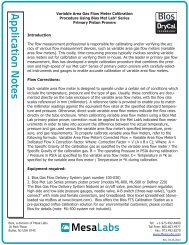
<strong>Variable</strong> <strong>Area</strong> Gas <strong>Flow</strong> <strong>Meter</strong> <strong>Calibration</strong><br />
Procedure Using Bios Met Lab ® Series<br />
Primary Piston Provers<br />
Introduction:<br />
The flow measurement professional is responsible for calibrating and/or verifying the accuracy of various flow measurement<br />
devices, such as variable area gas flow meters (variable area flow meters). This costly, time-consuming process typically<br />
involves sending variable area meters out for calibration or verifying them in-house. As the leader in primary gas flow<br />
measurement, Bios has developed a simple calibration procedure that combines the precision and high-speed of our<br />
Met Lab ® Series of primary piston provers with carefully-selected instruments and gauges to enable accurate calibration<br />
of variable area flow meters.<br />
<strong>Flow</strong> Corrections:<br />
Each variable area flow meter is designed to operate under a certain set of conditions which include the temperature,<br />
pressure and the type of gas. Usually, these conditions are documented directly on the tube enclosure of the variable area<br />
flow meter, with the flow rate scales referenced in mm (millimeter). A reference table is provided to enable you to match<br />
the millimeter readings against the equivalent flow rates at the specified standard temperature and pressure. Otherwise,<br />
direct scale variable area flow meters indicate the flow rates directly on the tube enclosure.<br />
When calibrating variable area flow meters using a Bios Met Lab primary piston prover, correction must be applied to<br />
the Met Lab’s indicated flow measurements in order to take into account the difference between the actual temperature,<br />
pressure and gas used versus the variable area flow meter’s specified temperature, pressure, and gas requirements.<br />
To properly calibrate variable area flow meters, refer to the following formula:<br />
<strong>Variable</strong> <strong>Area</strong> <strong>Flow</strong> <strong>Meter</strong>’s Corrected <strong>Flow</strong> = <strong>Variable</strong> <strong>Area</strong> <strong>Flow</strong> <strong>Meter</strong>’s Indicated <strong>Flow</strong> X Correction Factor<br />
Where:<br />
Correction Factor = √ (A x B x C)<br />
Where:<br />
1<br />
A = The Specific Gravity of the calibration gas as specified by the variable<br />
area flow meter / The Specific Gravity of the calibration gas<br />
B = The operating Pressure in PSIA during calibration / Pressure in PSIA<br />
as specified by the variable area flow meter<br />
C= Temperature in ºK as specified by the variable area flow meter /<br />
Temperature in ºK during calibration<br />
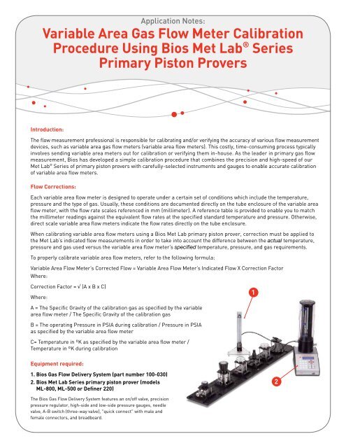
Equipment required:<br />
1. Bios Gas <strong>Flow</strong> Delivery System (part number 100-030)<br />
2. Bios Met Lab Series primary piston prover (models<br />
ML-800, ML-500 or Definer 220)<br />
2<br />
The Bios Gas <strong>Flow</strong> Delivery System features an on/off valve, precision<br />
pressure regulator, high-side and low-side pressure gauges, needle<br />
valve, A-B switch (three-way valve), "quick connect" with male and<br />
female connectors, and breadboard.
<strong>Variable</strong> <strong>Area</strong> Gas <strong>Flow</strong> <strong>Meter</strong> <strong>Calibration</strong><br />
Installation:<br />
Step 1<br />
Connect and/or verify all device connections. The Bios<br />
Gas <strong>Flow</strong> Delivery System comes with in-series, ¼” tubing<br />
connection of the on/off valve, pressure regulator,<br />
high-range pressure gauges, needle valve and A-B switch,<br />
as well as a “quick connect” with male/female connectors<br />
for connection of the on/off valve to the gas cylinder/<br />
compressed air<br />
Step 2<br />
Connect one end of the A-B switch to the inlet fitting of<br />
the variable area flow meter and the other end to the inlet<br />
fitting of your Met Lab<br />
Step 3<br />
Using the quick connect, connect the on/off valve to the<br />
gas cylinder/compressed air. Gas inlet pressure should<br />
be approximately 80 to100 psi<br />
Procedure:<br />
Step 1<br />
Close the needle valve, open the on/off valve and set<br />
the gas pressure by adjusting the pressure regulator<br />
to above 30 psi<br />
Step 2<br />
If the variable area flow meter contains a built-in needle<br />
valve, open its needle valve fully for unrestricted gas flow<br />
Step 3<br />
Turn on your Met Lab primary piston prover. Through<br />
its Setup menu, set your Met Lab’s pressure unit to ‘psi’<br />
and its flow readings to ‘Vol’ (Volumetric). For other flow<br />
measurement options (such as Continuous readings or the<br />
number of readings in the average), consult your Met Lab<br />
product manual<br />
Step 4<br />
Press your Met Lab’s Read button in order to record<br />
the ambient pressure and temperature<br />
Step 5<br />
Flip the A-B switch to the variable area flow meter and<br />
gradually begin to open the needle valve.<br />
Step 6<br />
Set the variable area flow meter’s flow at the desired<br />
level using the needle valve. The flow rate is indicated<br />
by the point on the printed scale where the float’s center<br />
stabilizes<br />
Step 7<br />
Wait one to two minutes for the float to stabilize.<br />
To ensure a particular flow point, flip the A-B switch back<br />
and forth a few times to check if the float returns to the<br />
previous scale point. If it needs adjustment, adjust the<br />
flow using the needle valve<br />
Step 8<br />
Record the low range pressure gauge’s pressure<br />
reading (in psia)<br />
Step 9<br />
If you are not using a direct scale variable area flow<br />
meter, record the reflected flow rate reading from<br />
the reference flow table against the floating point<br />
Step 10<br />
Refer to “<strong>Flow</strong> Corrections” in order to correct the<br />
variable area flow meter’s indicated flow for the<br />
operating temperature, pressure and the type of gas<br />
Step 11<br />
Flip the A-B switch to your Met Lab. Begin taking flow<br />
measurements with your Met Lab.<br />
Step 12<br />
Determine the full scale accuracy of the variable area<br />
flow meter using the following formula:<br />
% Accuracy = (Met Lab’s <strong>Flow</strong> Measurement - <strong>Variable</strong><br />
<strong>Area</strong> <strong>Flow</strong> <strong>Meter</strong>‘s corrected flow reading)*100 / <strong>Variable</strong><br />
<strong>Area</strong> <strong>Flow</strong> <strong>Meter</strong> Full Scale %<br />
Application Notes:<br />
• We recommend taking a minimum of ten flow measurements in an average. The more measurements in the average,<br />
the better the calibration results<br />
• Allow the Met Lab to stabilize before beginning a calibration<br />
• When calibrating a variable area flow meter, it’s best to use its specified calibration gas (calibrating with a surrogate<br />
gas can add greater uncertainty). If a surrogate must be used, we recommend using one with specific gravity similar<br />
to the gas the variable area flow meter is designed for
An Alternative Method of Calibrating <strong>Variable</strong> <strong>Area</strong> <strong>Flow</strong> <strong>Meter</strong> at Rated Temperature<br />
and Pressure Using MetLab Series Primary Piston Prover<br />
Introduction:<br />
The previous Bios method recommends calibration of a variable area flow meter (rotameter) by applying a correction<br />
factor to the Met Lab’s indicated flow reading for temperature and pressure, without subjecting the rotameter to the<br />
pressure specified for the variable area flow meter. This procedure is recommended as an alternative method for<br />
rotameter calibration where it will be subjected to its rated pressure using the Bios back pressure module. The back<br />
pressure module consists of a back pressure regulator and a pressure gauge<br />
<strong>Flow</strong> Corrections:<br />
Each variable area flow meter is designed to operate under a certain set of conditions which include the temperature,<br />
pressure and the type of gas. Usually, these conditions are documented on the tube enclosure of the rotameter.<br />
A reference table is provided to match the millimeter readings against the equivalent flow rates at the specified<br />
temperature and pressure. Otherwise, direct scale variable area flow meter indicates the flow rates directly<br />
on the tube enclosure.<br />
When calibrating a rotameter using a Bios MetLab piston prover, a flow correction factor (FCF) must be applied to the<br />
MetLab’s indicated flow measurement in order to take into account the difference between the actual temperature versus<br />
the rotameter’s rated temperature.<br />
In this procedure, no correction is applied for the pressure as the equipment set up is designed to calibrate the rotameter<br />
at rated pressure. Correction is applied to the MetLab’s indicated flow measurement only when the actual gas<br />
temperature differs to its rated temperature.<br />
<strong>Flow</strong> correction factor, FCF = 1/ √ {(calibration temp in 0F +460)/ (operating temp in 0F +460)}<br />
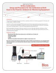
Set up diagram:<br />
On/ off<br />
valve<br />
Pressure<br />
regulator<br />
Pressure<br />
gauge<br />
Needle<br />
valve<br />
VA<br />
<strong>Meter</strong><br />
Pressure<br />
gauge<br />
Back<br />
pressure<br />
gauge<br />
DryCal<br />
Equipment required:<br />
1. Bios Gas <strong>Flow</strong> Delivery System, consists of on/off valve, pressure regulator, pressure gauge, needle valve<br />
2. Back pressure regulator and pressure gauge<br />
3. Bios Met Lab series Primary Piston Prover ( Models ML-800, ML-500, or Definer 220)<br />
Installation:<br />
Step 1<br />
Connect all the devices as per the set up diagram. Connect<br />
tubing from the back pressure regulator to the inlet of the<br />
DryCal and leave the outlet open to atmosphere<br />
Step 2<br />
The gas flow delivery system comes with a ‘Quick-<br />
Connect’ with male/female connector that connects the<br />
on/off valve to gas cylinder/compressed air. Connect the<br />
‘Quick-connect’ to the gas flow source. Gas pressure<br />
should be approximately 80 to 100 psi
Procedure:<br />
Step 1<br />
Turn on the MetLab. Through its set up menu, set the<br />
flow reading type to ‘STD’ and Temp Correction Factor to<br />
rated temperature of the rotameter<br />
Step 2<br />
Through the set up menu, enter the calculated flow correction<br />
factor (FCF) as a Sensor Factor in your MetLab if<br />
the actual gas temperature differs to the rated temperature<br />
of rotameter. Otherwise, set its value to default 1.00<br />
Step 3<br />
Close the needle valve, open the on/off valve, and set the<br />
gas pressure by adjusting the pressure regulator to 30 psi<br />
above the rotameter’s rated pressure<br />
Step 4<br />
If the rotameter contains a built-in needle valve,<br />
open its needle valve fully for unrestricted gas flow<br />
Step 5<br />
Step 6<br />
Set the variable area flow meter’s flow at desired<br />
level using the needle valve. The flow rate is indicated<br />
by the point on the printed scale where the float’s<br />
center stabilizes<br />
Step 7<br />
If you are not using a direct scale rotameter, record the<br />
reflected flow rate reading from the reference flow table<br />
against the floating point<br />
Step 8<br />
Press ‘Measure’ or ‘Read’ on the DryCal and begin<br />
taking readings<br />
Step 9<br />
Determine the full scale accuracy of the variable area<br />
flow meter using the following formula<br />
% Full scale accuracy = (MetLab’s flow reading – VAF’s<br />
indicated flow reading)/ VAF’s full scale %<br />
Open up the needle valve and adjust the back pressure<br />
regulator until the pressure gauge before the back pressure<br />
regulator indicates the rotameter’s rated pressure<br />
About Bios<br />
Bios is a recognized leader in primary gas flow measurement. We provide products, services and solutions for<br />
professionals in diverse disciplines, including environmental protection, occupational health and safety, industrial<br />
process control, research and development and calibration laboratories.<br />
Our Butler, New Jersey facility is one of the world’s most accurate gas flow measurement laboratories. Since 2004,<br />
we’ve been accredited to the calibration laboratory quality and proficiency standards set forth by ISO 17025, ANSI<br />
Z-540 and NIST Handbook 150, through the National Voluntary Laboratory Accreditation program (NVLAP) of the<br />
National Institute of Standards and Technology (NIST), the national lab of the United States.<br />
We’re pleased to state that our Scope of Accreditation uncertainty is ±0.071% of reading for gas flow measurements<br />
from 5 to 50,000 scc per minute. A current copy of our accreditation certificate and scope may be found on our website,<br />
at: http://www.biosint.com/pdf/NVLAP-accreditation.pdf.<br />
© 2011 Bios International Corporation MK01-119 Rev D