UNI 9490 FIREFIGHTING UNITS - Praktikpump.sk
UNI 9490 FIREFIGHTING UNITS - Praktikpump.sk
UNI 9490 FIREFIGHTING UNITS - Praktikpump.sk
- No tags were found...

You also want an ePaper? Increase the reach of your titles
YUMPU automatically turns print PDFs into web optimized ePapers that Google loves.
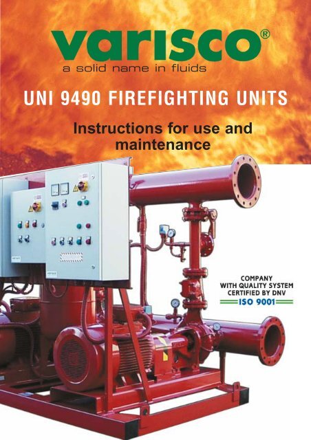
a solid name in fluids<br />
<strong>UNI</strong> <strong>9490</strong> <strong>FIREFIGHTING</strong> <strong>UNI</strong>TS<br />
Instructions for use and<br />
maintenance
VARISCO S.p.A.<br />
Servicing Department<br />
<strong>UNI</strong> <strong>9490</strong> Firefighting units<br />
Instructions for installation<br />
and maintenance
Before putting the unit into operation, read the instructions herein carefully.<br />
The unit has been thoroughly tested, for several hours, prior to delivery; performance has been checked and relevant<br />
requirements met, within the acceptable tolerance limits.<br />
If the instructions for use and maintenance are observed, the unit will give full performance for a long time. This<br />
manual also contains information for the prevention and elimination of most common operating problems.<br />
Contents:<br />
1 Identification<br />
2 Warranty<br />
3 General instructions<br />
4 Safety rules and accident prevention<br />
5 In case of emergency<br />
6 Handling and transport<br />
7 Storage<br />
8 Plumbing<br />
9 Wiring<br />
10 First startup and pressure switch settings<br />
11 Regular operation<br />
12 Periodic testing and maintenance<br />
13 System diagrams<br />
14 Electrically driven pump control panel diagram<br />
15 Electrically driven jockey pump control panel diagram<br />
16 <strong>UNI</strong> <strong>9490</strong> engine-driven pump control panel diagram<br />
17 List of spare parts<br />
18 Engine-driven pump control panel diagram<br />
19 Overall dimensions<br />
3
1 IDENTIFICATION<br />
1.1 Manufacturer<br />
VARISCO S.p.A. Zona Industriale Nord - Terza Strada, 9 - 35129 Padova - Italy<br />
1.2 Type<br />
Firefighting unit<br />
1.3 Model<br />
The model is given on the pump's nameplate<br />
1.4 Year of manufacture<br />
The year of manufacture is given on the pump’s nameplate<br />
1.5 Instruction book identification<br />
Compiled: May 2003 Edition: 04 Rev.: 01 Date of Revision:<br />
1.6 Ratings<br />
GRUPPO AUTOMATICO ANTINCENDIO<br />
AUTOMATIC <strong>FIREFIGHTING</strong> <strong>UNI</strong>T<br />
Anno / Year<br />
Peso / Weight<br />
kg<br />
Matricola / Serial No.<br />
VARISCO S.p.A. - PADOVA - ITALY - 049 82 94 111<br />
TYPE<br />
MATR.<br />
ITEM<br />
m 3 /h (max) m (max) kW RPM (max) kg<br />
Ratings refer to testing with water at 20°C and with a density of 1,000 kg/m 3<br />
Type :indicates the model of the pump and unit (pump/gearbox/engine/motor).<br />
Serial No. : this is the pump’s serial number<br />
Item : this is the number with which the pump is associated in the agreement documents (not always<br />
indicated).<br />
m 3 /h (max) : this is the pump’s maximum flow rate, measured at top speed (rpm).<br />
m (max) : this is the pump’s maximum working pressure, measured at top speed (rpm).<br />
kW : it is the maximum power applicable to the pump at the maximum rpm<br />
RPM (max) : this is the pump’s maximum operating speed. The pump must never be allowed to exceed this<br />
speed.<br />
kg : it is the weight of the unit (pump and trailer) not including the weight of the water in the pump<br />
casing and that of the fuel in the tank.<br />
1.7 Field of application<br />
Firefighting Unit suitable for pumping soft water not containing solids in suspension used to supply water to<br />
an automatic firefighting system.<br />
1.8 In case of breakdown<br />
Call the following number:<br />
+39 049 82 94 111<br />
4
2 WARRANTY<br />
- VARISCO POMPE warrants that only top-quality materials are used in the construction of their pumps and<br />
that machining and assembly are carried out to high standards.<br />
- The company also warrants units supplied, in conformity with general terms of sale, against defective<br />
materials or faulty workmanship for a period of 12 months from the date said units are put into operation, and<br />
under no circumstances for more than 18 months from the material’s date of delivery.<br />
- The warranty is not valid if the unit has been tampered with by third parties.<br />
- Replacement of parts or of the whole unit can only be carried out after careful examination by our technical<br />
personnel.<br />
- The warranty includes the supply of parts acknowledged as being defective by the manufacturer, and does<br />
not cover labour and transport costs, where applicable.<br />
- This warranty does not cover materials subject to deterioration or normal wear and tear (seals, diaphragms,<br />
pressure and vacuum gauges, rubber or plastic items, etc.) or damage caused by misuse or improper<br />
handling of the unit by the end user.<br />
- Materials replaced under warranty become the property of VARISCO POMPE.<br />
3 GENERAL INSTRUCTIONS<br />
The goods must be examined on arrival to ascertain any damage, particularly that incurred in transit. Also<br />
check that the goods correspond exactly to the description on the shipping documents.<br />
Report any differences or damage to the forwarding agent straight away, and inform the Padua office or local<br />
distributor within 48 hours (see list attached, or look under "Pumps - Production" in the Yellow Pages).<br />
Always quote the pump type printed on the relevant nameplate, or the serial number.<br />
The Firefighting Unit must be used only for applications for which the Manufacturer has specified:<br />
- construction materials<br />
- operating conditions (pressure, speed, temperature, etc.)<br />
- fields of application<br />
For any applications not contemplated by the Manufacturer, contact VARISCO POMPE's Servicing<br />
Department.<br />
4 SAFETY RULES AND ACCIDENT PREVENTION<br />
pict. 1<br />
pict. 2 pict. 3 pict. 4<br />
pict. 5<br />
When working near the Firefighting Unit, dress appropriately, avoiding baggy<br />
clothes with loose items (ties, scarves, etc.), which could get caught in moving<br />
parts. Use overalls made according to safety regulations, gloves, insulating<br />
shoes, safety glasses, safety earmuffs and hard hat. (fig. 1)<br />
Do not carry out maintenance on the engine while it is running (fig. 2).<br />
Keep hands away from moving parts (e.g. belts, couplings, etc.) (fig. 3).<br />
Keep hands away from parts of the engine that get hot (fig. 4).<br />
Do not climb on top of the Firefighting Unit to perform work of any kind.<br />
Do not rest metal tools on the battery (fig. 5).<br />
5
5 IN CASE OF EMERGENCY<br />
Switch off motors/engines via the relevant control panels.<br />
Notify the person responsible for running the plant.<br />
6 HANDLINGS AND TRANSPORT<br />
6.1 Method of transport<br />
The unit must be transported horizontally and safely.<br />
Do not linger within the Firefighting Unit’s range during its handling.<br />
6.2. Installation<br />
During installation and maintenance, all components used must be handled securely using suitable slings.<br />
Handling must be carried out by specialized personnel to avoid damage to the Unit and injury of personnel.<br />
Only use the lifting rings the Firefighting Unit comes with<br />
Maximum lifting speed: Vmax = 0.5 m/s<br />
7 STORAGE<br />
Protected from the elements and away from aggressive atmospheres.<br />
8 PLUMBING<br />
8.1 Suction piping (Ref. diagrams on page 10)<br />
Where possible, the unit should be installed with flooded suction.<br />
If the unit is installed above the water supply, with the suction ports higher than the water’s minimum level, a<br />
priming tank must be installed for each pump, complete with accessories provided for by <strong>UNI</strong> <strong>9490</strong> standards.<br />
Each pump will also be fitted with its own nonreturn valve (part 6). Each pump will have an independent<br />
suction pipe, with relevant isolating gate valve (parts 8 - 9) so that the pump can be serviced (for instance:<br />
the pump disassembled or the relevant nonreturn valve cleaned) without having to empty the storage tank.<br />
The electrically driven jockey pump, where applicable, will also have an independent suction pipe. Warning:<br />
ALWAYS install the nonreturn valve on the actual pump’s suction port, complete with three-way fitting so that<br />
it can be serviced.<br />
This valve is required even if the pump is a self-priming model as, without it, the pressure vessel used for<br />
storage would empty through the actual pump as soon as it stops.<br />
If you have to install a single suction manifold, consult our Technical Department for sizing.<br />
Suction pipes must have the same diameter as the relevant pump’s suction port, or larger still if piping is<br />
particularly long or flow resistance high (bends, elbows etc.).<br />
It is always essential you fit a flanged length of pipe or vibration damping coupling, in addition to the isolating<br />
gate valve, so that each pump can be disassembled.<br />
8.2 Delivery piping<br />
The discharge manifold has two flanges to simplify connections when dealing with ring main systems. If just<br />
one flange is used, the free one can be used for recirculating purposes (see section below).<br />
8.3 Recirculation piping for periodic tests (Ref. diagrams on page 10)<br />
To simplify periodic testing of operation, it is best to connect the discharge manifold to the storage tank with<br />
a ball valve and a _“ or 1” pipe, depending on the size of the unit (part 13).<br />
The resulting recirculation allows you to simulate a pressure drop and hence automatic starting, without<br />
turning on hydrants or sprinklers and without using water.<br />
Each pump comes with a flange with gate valve (part 8) fitted to measure the capacity of the actual unit.<br />
Where fitted, the flow meter (part 15) must be installed in a straight length of piping at least ten times the<br />
diameter of the pipe, both before and after the meter in question. (Example: DN100 pipe; 100x10= 1000;<br />
requires a stretch of pipe at least 1 metre long, before and after the meter.<br />
8.4 Automatic recirculation piping (Ref. diagrams on page 10)<br />
To avoid pumps working too long with zero flow when the installation site is not always manned, it is advisable<br />
to install an automatic recirculation system. Units start automatically but are stopped manually, meaning they<br />
may remain in operation for a long time before they are stopped, resulting in the danger of water in the pumps<br />
6
overheating, generating steam, causing the pump casing to break and destroying the seal as a result.<br />
Each main pump features a fitting for the recirculation pipe (part 9A) at the base of the delivery flange, where<br />
there is a tee for the pressure gauge, a 1” fitting (part 17) (provided for connecting the priming tank when a<br />
flooded suction system is not used) and a ball valve downline to which a device (calibrated diaphragm or cock)<br />
must be connected to set the recirculation capacity. (part 14).<br />
For this purpose, balancing valves (10 or 20 turns) such as those used in heating systems (1/2” or 3/8”<br />
Cazzaniga or Giacomini models) can be used. At this point, with the pump stopped, the only pressure will be<br />
the static pressure due to the head of the water supply. When the pump starts running, the flow circulated as<br />
a result of the delivery pressure will be in proportion to the opening of the balancing valve, and the pressure<br />
switch (part 7) will indicate that the relevant pump is running. A capacity of 10-20 litres/minute is sufficient to<br />
avoid damaging the pumps.<br />
8.5 Packed glands leak discharge piping<br />
<br />
Each main pump features a cast tray to collect water leaking from the packed gland. (It is located between the<br />
rear of the pump and the bearing housing). These trays have tapped holes to accommodate pipes conveying<br />
the waste water outside.<br />
Warning: The room the unit is to be installed in must be kept at a minimum temperature of 5-6 °C to avoid<br />
the danger of freezing, and must feature a ventilation system so that the diesel engine is kept cool.<br />
Warning, danger of death by asphyxiation! The diesel engine exhaust must always be ducted outside.<br />
A length of hose must be fitted between the end of the diesel engine exhaust silencer and the pipe conveying<br />
exhaust fumes outside to isolate vibrations between the engine and the pipe fixed rigidly to the building.<br />
9 WIRING<br />
Each pump has its own control box. If setting up a power supply line to each control box is a problem, a<br />
connector box can be installed in the pump room to power the various control boxes.<br />
9.1 Engine-driven pump only<br />
A single-phase 220 V 50 Hz supply is sufficient. Required power 700 VA. In special cases, with engines over<br />
200 HP, water-cooled engines etc., more power may be required. In such cases, consult the Technical<br />
Department.<br />
9.2 Electrically driven pump or unit with more than one electrically driven pump and engine-driven pump<br />
A three-phase line, with neutral, is required, with enough power to meet the total rated power of the electrically<br />
driven pumps. Unless otherwise requested, a 3x380 V, 50 Hz power supply will be taken as standard.<br />
The cross-section of the neutral wire should be calculated for the power of the engine-driven pump plus that<br />
required by auxiliary equipment in the pump room (lights, sockets, electric heater if fitted).<br />
Control boxes feature an earth terminal, which must be connected by the unit’s user to the earth wire. (Italian<br />
presidential decree (D.P.R.) 547 for prevention of accidents in the workplace). Star/delta starters are used for<br />
electrically driven pumps with a power over 7.5 kW (10 HP). Consequently, the circuit breaker protecting the<br />
unit’s supply line must have a magnetic trip designed to carry at least 2.5 times the rated current of the<br />
electrically driven pump, or the sum of the rated current of each electrically driven pump if there is more than<br />
one. Phase sequence can be checked to ensure that phases have been connected correctly without having<br />
to start the electrically driven pumps, by checking the mains phase sequence control device in the electrically<br />
driven pump control box: when the box is powered, the red LED on the actual device should light. If this is<br />
not the case, swap two of the phase wires over in the input terminal box in the control box without touching<br />
the wiring of the individual motors.<br />
Next, check direction of rotation by starting each electrically driven pump for a moment using the relevant<br />
manual control: motors should turn CLOCKWISE looking from the fan end.<br />
10 FIRST STARTUP AND PRESSURE SWITCH SETTINGS<br />
10.1 Jockey pump testing<br />
IIf there is a jockey pump, bleed the air out of its casing through the plug provided. Check the pressure vessel’s<br />
pressure setting: recommended value 2.5-3.5 bar depending on the system’s working pressure. Start the<br />
pump by turning the selector to "AUTOMATIC". The pump should prime and fill the system. The working<br />
pressure is given on the pressure gauge located on the discharge manifold (part 5), or on the one located on<br />
the pressure vessel. The next step is to bleed the ring main, opening the gate valves of the fire hydrants or<br />
outlets. When the recirculation line or a hydrant is opened, the jockey pump starts working. It is controlled by<br />
7
the two pressure switches fitted on the actual pump’s delivery (part 5); one controls starting and the other<br />
stopping.<br />
Recommended values: START : 4 - 5 bar STOP: 5 - 6 bar.<br />
If pressure in the system does not increase, there may be a leak in the ring main or in the foot valves of the<br />
main pumps (if fitted).<br />
10.1.1 “SPLIT-CASE” electrically driven pump<br />
Warning: Danger of damaging the pump! Do NOT start the electric motor before performing the<br />
following check<br />
If “split-case” electrically driven pumps are fitted (pumps with the case split horizontally and with the rotating<br />
parts on the lower half of the case carrying the flanges and pipework), the pumping unit is sent with the flexible<br />
drive coupling open. Consequently, BEFORE starting the electric motor, take off the coupling guard and make<br />
sure the coupling is actually open. That done, refit the coupling guard, start the motor and make sure the<br />
direction of rotation matches the direction indicated on the pump.<br />
Close the coupling to couple the motor to the pump, refit the coupling guard and move on to point 10.2.<br />
punto 10.2.<br />
10.2 Electrically driven pump test (Ref. diagrams on page 10))<br />
If there is an electrically driven pump, testing will proceed by turning the relevant selector to “AUTOMATIC”<br />
and reducing the pressure in the system by opening either the recirculation valve (part 13) or a hydrant.<br />
Check starting pressure on the pressure gauge fitted on the discharge manifold.<br />
Warning: the pressure gauge fitted on the expansion tank gives the pressure in the tank, not system<br />
pressure, because there is a nonreturn valve (part 6) between the jockey pump and the discharge manifold.<br />
Recommended value for electrically driven pump start: approx. 1 bar less than the starting pressure of the<br />
jockey pump.<br />
The electrically driven pump is stopped manually only, in compliance with the regulations in force (<strong>UNI</strong> <strong>9490</strong>).<br />
10.3 Engine driven pump test (Ref. diagrams on page 12)<br />
<br />
Warning: The diesel engine produces poisonous exhaust gases. Make sure the room is well<br />
ventilated. Protect ears with earmuffs or earplugs. Be particularly careful around hot engine parts<br />
(exhaust pipe, manifolds, cylinder head).<br />
Before carrying out this test, switch on the master switch on the engine-driven pump’s control panel to pre<br />
heat the engine oil (2 - 4 hours depending on ambient temperature). If you do not have the time, set the<br />
accelerator to idling speed to avoid starting up at full speed the first time while the engine is cold. After a few<br />
minutes running at idling speed, bring the engine gradually up to running speed.<br />
As for the electrically driven pump, turn the selector to “AUTOMATIC” and reduce system pressure by means<br />
of the valve (part 13), reading pressure off the gauge on the discharge manifold (part 5).<br />
Recommended value for engine-driven pump start: 1 bar less than the starting pressure of the electrically<br />
driven pump. The engine-driven pump is stopped manually only, in compliance with the <strong>UNI</strong> <strong>9490</strong> regulations.<br />
<br />
Warning: If the accelerator setting has been changed from the desired speed (check the delivery pressure or<br />
revolution counter), reset the accelerator to the desired position.<br />
If starting pressures are not the ones you actually want, adjust the pressure switches accordingly. When the<br />
unit is started for the first time, run the pumps for at least 20-30 minutes before tightening the gland.<br />
Warning: do not tighten to the point of stopping the dripping completely, because if water does not drip from<br />
the gland, the seal is not lubricated and the shaft will quickly be damaged.<br />
11 REGULAR OPERATION<br />
All selectors should be kept on “AUTOMATIC”; only in this position can the selector keys be removed. If there<br />
are minor leaks from the system or nonreturn valves, the electrically driven jockey pump will run for as long<br />
as necessary to replace the amount of water that has been lost by the system. If, on the other hand, a fire<br />
hose is turned on, said pump will come on to restore pressure in the system: if the capacity required by the<br />
fire hose is greater than that provided by the jockey pump, the pressure will fall still further to the point where<br />
the main electrically driven pump starts.<br />
If pressure does not rise (electrically driven pump fault, mains power failure, water demand excessive), the<br />
engine-driven pump will also start.<br />
8
Warning: If there is a power failure or mains power is switched off because of work on the line, any<br />
pressure drop in the system will cause the engine-driven pump to start automatically.<br />
12 PERIODIC TESTING AND MAINTENANCE (Ref. diagrams on page 10)<br />
12.1 The unit should be tested at least every 15 days to assure lasting reliability.<br />
To carry out the test, one pump at a time should be switched off by setting the relevant selector to 0, and<br />
a fire hydrant or the recirculation valve (part 13) on the discharge manifold then opened to check whether<br />
the other pump starts automatically.<br />
12.1.1 Electrically driven pump test<br />
Check the ammeter reading to make sure that current absorbed by the electrically driven pump does not<br />
exceed the electric motor’s rated current demand.<br />
Make sure there are no vibrations or unusual noises, which might be the result of worn rubber dowels in<br />
the flexible coupling, or the motor or pump bearings.<br />
12.2 Check the pump glands: they should drip slightly (about one drop every 20 seconds).<br />
12.3 Engine driven pump test<br />
Start the engine-driven pump in both automatic and manual mode. Make sure there are no vibrations<br />
orunusual noises, which might be the result of worn rubber dowels in the flexible coupling, or the pump<br />
bearings. Check for oil or diesel fuel leaks. Check the pump’s packed gland: it should drip slightly.<br />
12.3.1 Check the level of battery liquid, adding distilled water only if required. Check the instruments on the control<br />
panel (voltmeters and ammeters) to ascertain the battery charge.<br />
12.3.2 Check diesel fuel and lubricating oil levels for the engine and pump mounts.<br />
12.3.3 Check the engine oil preheat system (touch the sump before the engine is started: its temperature should<br />
be about 60° C).<br />
12.3.4 Change diesel engine oil at least once a year. Continual preheating causes oil to deteriorate even if the<br />
engine only actually runs for a few hours altogether.<br />
12.4 Check the pressure vessel’s pressure setting every year. This check should be carried out after draining<br />
water from the pressure vessel through the cock (part 9), otherwise the pressure reading on the filler valve<br />
will not be reliable.<br />
12.5 Check that the warning lights on the electrically driven pump control boxes are operating: since there are<br />
two of each, operation can be checked immediately. If in any doubt as to the plumbing or wiring of units, or<br />
their operation, and if you need to request service, contact our Servicing Department at this address:<br />
VARISCO S.p.A.<br />
Zona Industriale Nord Terza Strada, 9 35129 PADOVA<br />
Phone: + 39 049 8294111 - Fax + 39 049 8076762<br />
9
13 SYSTEM DIAGRAMS<br />
10
11<br />
MAINS<br />
ELECTRICALLY<br />
DRIVEN PUMP<br />
N.B. IN NORMAL CONDITIONS<br />
WITH FEEDED DEVICE<br />
10-11 CLOSED<br />
10-12 OPEN<br />
WITH NO TENSION OR IN<br />
ALARM<br />
10-11 OPEN<br />
10-12 CLOSED<br />
VOLTMETER<br />
SWITCH<br />
ALARM<br />
14 ELECTRICALLY DRIVEN PUMP CONTROL PANEL DIAGRAM (1 of 2)
14 ELECTRICALLY DRIVEN PUMP CONTROL PANEL DIAGRAM (2 of 2)<br />
MAINS<br />
(green)<br />
LINE<br />
RUNNING<br />
(red)<br />
RUNNING<br />
LINE<br />
ELECTRICALLY<br />
DRIVEN PUMP<br />
PRESSURE<br />
SWITCH<br />
(green)<br />
LINE<br />
ESCLUDED<br />
PUMP<br />
12
15 ELECTRICALLY DRIVEN JOCKEY PUMP CONTROL PANEL DIAGRAM WITH MAIN<br />
ELECTRICALLY DRIVEN PUMP AUTOMATIC STOP (<strong>UNI</strong> 10779)<br />
S 1<br />
SELECTOR<br />
MAINS<br />
green<br />
STOP<br />
orange<br />
RUNNING<br />
green<br />
MAINS<br />
380 V / 50 Hz<br />
JOCKEY PUMP<br />
2,2 kW<br />
STOP<br />
RUNNING<br />
STOP RUNNING<br />
PRESSURE SWITCHES<br />
(closed with no pressure)<br />
S 2<br />
AUTOMATIC STOP<br />
CONNECTION<br />
ON REQUEST<br />
for automatic stop<br />
STOP PRESSURE<br />
SWITCH<br />
(open with no pressure)<br />
STOP<br />
PUMP 1<br />
STOP<br />
PUMP 2<br />
STOP<br />
PUMP 3<br />
STOP<br />
PUMP 4<br />
13
16 <strong>UNI</strong> <strong>9490</strong> ENGINE DRIVEN PUMP CONTROL PANEL<br />
Description<br />
The panel is used to manage an engine-driven pump<br />
automatically or in manual mode meeting standards<br />
<strong>UNI</strong><strong>9490</strong> - <strong>UNI</strong>10779.<br />
It is made up of:<br />
1 electronic circuit board with display<br />
2 battery charger ammeters<br />
1 “automatic,manual,open” selector with key removable<br />
when set to automatic only<br />
2 battery chargers<br />
1 double-pole thermomagnetic circuit breaker for mains input<br />
1 thermomagnetic circuit breaker for engine preheating<br />
2 forced start buttons<br />
Description of Electronic Control Unit with Display<br />
The control unit is made up of:<br />
1 LED indicating selector set to OPEN<br />
1 LED indicating selector set to AUTOMATIC<br />
1 LED indicating selector set to MANUAL<br />
1 STOP button<br />
1 START button<br />
1 RESET button<br />
1 OK button (TO SELECT READINGS/SETTINGS PAGES ON DISPLAY)<br />
2 buttons (. = next and . back) for programming the board<br />
1 display for viewing:<br />
Operating mode<br />
❏ Selector set to AUTOMATIC<br />
❏ Selector set to MANUAL<br />
❏ Selector set to OPEN<br />
Parameter values:<br />
❏ Engine rev counter<br />
❏ Voltage of battery-1<br />
❏ Voltage of battery-2<br />
❏ Maintenance hours<br />
❏ Hours of operation<br />
❏ Number of starts battery-1<br />
❏ Number of starts battery-2<br />
❏ Number of failed starts battery-1<br />
❏ Number of failed starts battery-2<br />
Alarms:<br />
❏ Oil pressure<br />
❏ Voltage battery-1<br />
❏ Voltage battery-2<br />
❏ Charger fault battery-1<br />
❏ Charger fault battery-2<br />
❏ No mains power<br />
❏ Engine battery charger alternator<br />
Button functions:<br />
RESET: resets alarms<br />
SELECT READINGS/SETTINGS PAGES ON DISPLAY (OK):<br />
scrolls through the display’s various values or alarms displayed<br />
STOP: stops the engine with selector set to manual<br />
START: starts the engine with selector set to manual<br />
:next (during programming)<br />
: back (during programming)<br />
14
16.1 VALUES ON DISPLAY<br />
in standby condition<br />
HOURS BAT 1 BAT 2<br />
0000 12.0 12.0<br />
Notes: press the RESET key to view the selector’s setting<br />
During operation, four pages can be viewed on the display giving readings and values of settings. To move from one page to<br />
the next, press OK<br />
RPM V. BAT 1 V. BAT 2<br />
A) B)<br />
0000 12.0 12.0<br />
HOURS/MAIN REV COUNTER<br />
0000 0000<br />
C)<br />
AV.BAT1<br />
AV.BAT2<br />
D)<br />
0000 0000<br />
AF.BAT1<br />
AF.BAT2<br />
0000 0000<br />
16.2 AUTOMATIC mode<br />
Set the selector to “Automatic”<br />
The message AUTOMATIC MODE appears on the display and the relevant LED lights.<br />
The engine starts automatically following a drop in system pressure downline, reported by the contact of one of the pressure<br />
switches closing. If one of the batteries is insufficient, the control unit automatically switches starting onto the other battery.<br />
In either case, there will be 10 attempts to start. The engine can be stopped manually by turning the selector to OPEN or<br />
MANUAL<br />
WARNING!!!!<br />
When working as a <strong>UNI</strong>10779-compliant unit (where activated), operating logic is identical to the above, the only<br />
difference being that the engine-driven pump stops automatically once pressure has remained constantly above the<br />
actual pump’s starting pressure for at least 30 minutes running.<br />
16.3 MANUAL mode<br />
Set the selector to “Manual”.<br />
The message MANUAL MODE appears on the display and the relevant LED lights.<br />
To start the engine, hold the START button down until you see that the engine has started (the display reads “ENGINE<br />
STARTED”).<br />
To stop the engine, press STOP<br />
16.4 OPEN mode<br />
Set the selector to “Open”<br />
The message OPEN STATUS appears on the display and the relevant LED lights.<br />
With the selector in this position, no operation can be performed other than programming the board.<br />
16.5 FORCED START mode<br />
Whatever the selector’s setting, the engine’s forced start can be carried out by pressing one of the two<br />
buttons on the panel and also selecting which battery is to be used. To stop the engine: press the STOP<br />
button near the forced starting buttons or intervene mechanically on the engine.<br />
With this kind of starting, the board does not run any check on engine parameters<br />
16.6 ALARMS mode<br />
If there is an alarm, the control unit sends a relevant warning up on the display.<br />
16.7 SETTING THE REV COUNTER (RPM)<br />
Only perform the first timthe unit is put into service. Proceed as follows:<br />
1 START THE ENGINE: set the selector to MANUAL and press START<br />
2 PRESS KEYS . and STOP at the same time, holding them down for at least 4 seconds<br />
3 THE DISPLAY READS:<br />
RPM ADAPT.x 10<br />
DF=<br />
NEW=<br />
The number next to NEW flashes<br />
4 PRESS OK (the number stops flashing)<br />
5 PRESS to increase or to decrease. The number set must match the actual number<br />
of engine rpm multiplied by 10. (For instance, if the engine runs at 580 rpm, set 0058)<br />
6 PRESS OK TO CONFIRM. The number starts to flash again and also appears next to DF<br />
THE REV COUNTER IS SET<br />
7 PRESS STOP<br />
15
16.8 OPTIONS menu description (RESET+OK)<br />
Via this part of the program, the user can edit a number of functions. This must be performed with the engine stopped<br />
To call up the menu, proceed as follows:<br />
1 Press RESET<br />
2 Press OK (for 3 seconds)<br />
THE FIRST MESSAGE APPEARS:<br />
DF=<br />
ALTERN.STARTS<br />
NEW=<br />
DF indicates the value set<br />
NEW, which is flashing, is the position<br />
where the new value will be entered<br />
PRESS: .<br />
to move on to the next message<br />
to move back to the last message<br />
Once you have chosen the parameter, follow the procedure to edit its value.<br />
Press OK: the value next to NEW stops flashing<br />
Press to increase or to decrease the value.<br />
Press OK to confirm: the value starts flashing again.<br />
The entry is now saved: press or again to move to another parameter, or press RESET to exit the OPTIONS menu<br />
16.8.1 List of OPTIONS menu parameters (RESET + OK)<br />
If there is a failed start, via this parameter you can decide<br />
YES<br />
1<br />
whether to perform the next attempt on the other battery,<br />
alternating between the two until the maximum number of<br />
attempts is reached (YES), or whether to perform all attempts on<br />
one battery first and only then switch to the other (NO).<br />
ALTERN. STARTS<br />
Whatever the case, if one battery is too low, the cycle <strong>sk</strong>ips it<br />
YES<br />
2 Total number of starts NO.AUTOM.START 0020<br />
3 Time between two consecutive starting attempts START TIMER 0007<br />
4 Time between starting attempts in automatic mode TIME BETW.AUT.STA 0005<br />
5 Engine stop phase time STOP TIME 0010 0000 0250<br />
6 Length of audible signal before start PRESTART SOUND 0002<br />
7 Length of audible alarm warning ALARM SOUND TIME 0020 0000 0250<br />
8 Alarm log display ALARM LOG ALARM LOG<br />
NO<br />
0000 0040<br />
17 LIST OF SPARE PARTS<br />
N. Component Manufacturer Reference-item<br />
1 Box ZANARDO<br />
404<br />
2 Battery charger LOVATO<br />
LBC0312<br />
3 <strong>UNI</strong> <strong>9490</strong> board TECNO ELETTRA<br />
206032H<br />
4 Ammeters RS 244834<br />
5 Buttons LOVATO 82003<br />
6 Terminals PHOENIX<br />
7 Switches MOELLER/AEG<br />
8 Selector LOVATO SF30<br />
16
18 ENGINE-DRIVEN PUMP WIRING DIAGRAM<br />
STARTER<br />
MOTOR<br />
SWITCH<br />
STATUS<br />
17
19 OVERALL DIMENSIONS<br />
Unit type A B C1 C M - O N X kg<br />
A2-40C/6LD 435/Mc 752/JET kW2 1500 1500 1800 DN50 PN10 1 1 /4” DN80 PN16 750<br />
A2-40 A/7LD 665/Mc 1002/JET kW2 1500 1500 1800 DN50 PN10 1 1 /4” DN80 PN16 800<br />
HMU 40 2-2/7LD 665/Mc 1002/JET kW2 1500 1500 1800 DN65 PN10 1 1 /4” DN80 PN16 800<br />
A2-50C/7LD 665/Mc 1002/JET kW2 1500 1500 1900 DN65 PN10 1 1 /4” DN80 PN16 800<br />
A2-50A/MD 190/Mc 1502/JET kW2 1500 1500 1900 DN65 PN10 1 1 /4” DN80 PN16 800<br />
A3-50 D/9LD 561-2/Mc 2002/JET kW2 1500 1500 1900 DN65 PN10 1 1 /4” DN80 PN16 880<br />
A3-50 B/9LD 625-2/Mc 2502/JET kW2 1500 1500 1900 DN65 PN10 1 1 /4” DN80 PN16 880<br />
A3-50 A/5LD 825-2/Mc 3002-3/JET kW2 1500 1500 1900 DN65 PN10 1 1 /4” DN80 PN16 900<br />
A2-65 C/9LD 561-2/Mc 2002-3/JET kW2 1500 1500 1900 DN80 PN10 1 1 /4” DN80 PN16 900<br />
A2-65 A/9LD 625-2/Mc 2502/JET kW2 1500 1500 1900 DN80 PN10 1 1 /4” DN80 PN16 900<br />
A3-65 D/5LD 825-2/Mc 3002/JET kW2 1500 1500 2000 DN80 PN10 1 1 /4” DN80 PN16 1100<br />
A3-65 B/5LD 824-3B/Mc 4002/JET kW2 2000 1800 1600 DN80 PN10 1 1 /4” DN125 PN16 1150<br />
A2-80 C/5LD 825-2/Mc 3002-3/JET kW2 1500 1500 2000 DN100 PN10 1 1 /4” DN80 PN16 1050<br />
A2-80 A/5LD 824-3B/Mc 4002/JET kW2 2000 1800 1800 DN100 PN10 1 1 /4” DN125 PN16 1200<br />
A3-80 E/5LD 824-3B/Mc 4002/JET kW2 2000 1800 1800 DN100 PN10 1 1 /4” DN125 PN16 1200<br />
A3-80 C/MSM 1000.3A/Mc 6002-3/JET kW2 2000 1800 1800 DN100 PN10 1 1 /4” DN125 PN16 1650<br />
A3-80 B/MSM 1000.3A/Mc 6002-3/JET kW2 2000 1800 1800 DN100 PN10 1 1 /4” DN125 PN16 1650<br />
A3-80 A/MSM 1000.4A/Mc 7502-3/JET kW2 2300 2000 1800 DN100 PN10 1 1 /4” DN150 PN16 1800<br />
A004-80 D/MSM 1000.4A/Mc 7502-3/JET kW2 2300 2000 1800 DN100 PN10 1 1 /4” DN150 PN16 1800<br />
A2-100 A/MSM 1000.3A/Mc 6002-3/JET kW2 2000 1800 1800 DN125 PN10 1 1 /4” DN125 PN16 1700<br />
A3-100 D/MSM 1000.4A/Mc 7502-3/JET kW2 2300 2000 1900 DN125 PN10 1 1 /4” DN150 PN16 1900<br />
A3-100 C/MSM 1000.4A/Mc 7502-3/JET kW2 2300 2000 1900 DN125 PN10 1 1 /4” DN150 PN16 1900<br />
AZH4-100 D/A3-100 B/VM 4105T/Mc 10002/JET kW2 2600 2300 2000 DN125 PN10 1 1 /4” DN150 PN16 2100<br />
AZH4-100 C/A3-100A/VM 4105T/Mc 10002/JET kW2 2600 2300 2000 DN125 PN10 1 1 /4” DN150 PN16 2100<br />
AZRBH3-125 E/AZRBH2-125 C/VM 6105T/Mc 12502/JET kW2 2600 2300 2000 DN150 PN10 1 1 /4” DN200 PN16 2700<br />
AZRBH3-125 B/AZRBH2-125 A/VM 6105 I/Mc 15002/JET kW2 2600 2300 2000 DN150 PN10 1 1 /4” DN200 PN16 3000<br />
18
VARISCO S.p.A.<br />
Zona Industriale Nord - Terza Strada, 9 - 35129 PADOVA - Italy<br />
Tel. +39 049 82 94 111 - Fax +39 049 80 76 762 - e-mail: export@variscospa.com<br />
Web site : www.variscospa.com<br />
Edition 04 Rev. 01 (TCE)