Operating Instructions (Compact) Issue 11/04 SINAMICS ... - Siemens
Operating Instructions (Compact) Issue 11/04 SINAMICS ... - Siemens
Operating Instructions (Compact) Issue 11/04 SINAMICS ... - Siemens

Create successful ePaper yourself
Turn your PDF publications into a flip-book with our unique Google optimized e-Paper software.
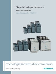
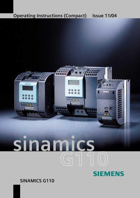
<strong>Operating</strong> <strong>Instructions</strong> (<strong>Compact</strong>) <strong>Issue</strong> <strong>11</strong>/<strong>04</strong><br />
sinamics<br />
<strong>SINAMICS</strong> G<strong>11</strong>0
Warnings, Cautions and Notes <strong>Issue</strong> <strong>11</strong>/<strong>04</strong><br />
The <strong>Compact</strong> version of the <strong>Operating</strong> <strong>Instructions</strong> will cover the majority of<br />
typical applications. It is valid for inverters firmware versions 1.0 and 1.1. For<br />
full details please refer to the <strong>Operating</strong> <strong>Instructions</strong> and the Parameter List.<br />
Warnings, Cautions and Notes<br />
The following Warnings, Cautions and Notes are provided for your safety and as a<br />
means of preventing damage to the product or components in the machines<br />
connected.<br />
Specific Warnings, Cautions and Notes that apply to particular activities are<br />
listed at the beginning of the relevant chapters and are repeated or supplemented<br />
at critical points throughout these chapters.<br />
Please read the information carefully, since it is provided for your personal safety<br />
and will also help prolong the service life of your <strong>SINAMICS</strong> G<strong>11</strong>0 Inverter and the<br />
equipment you connect to it.<br />
!<br />
WARNING<br />
‣ This equipment contains dangerous voltages and controls potentially<br />
dangerous rotating mechanical parts. Non-compliance with Warnings or failure<br />
to follow the instructions contained in this manual can result in loss of life,<br />
severe personal injury or serious damage to property.<br />
‣ Only suitable qualified personnel should work on this equipment, and only after<br />
becoming familiar with all safety notices, installation, operation and<br />
maintenance procedures contained in this manual. The successful and safe<br />
operation of this equipment is dependent upon its proper handling, installation,<br />
operation and maintenance.<br />
‣ The DC link of all <strong>SINAMICS</strong> G<strong>11</strong>0 modules remains at a hazardous voltage<br />
level for 5 minutes after all voltages have been disconnected. Therefore always<br />
wait for 5 minutes after disconnecting the inverter from the power supply before<br />
carrying out work on any modules. The drive unit discharges itself during this<br />
time.<br />
‣ The mains input, DC and motor terminals carry dangerous voltages even if the<br />
inverter is inoperative, wait 5 minutes to allow the unit to discharge after<br />
switching off before carrying out any installation work.<br />
‣ During the parameter download with the STARTER commissioning tool or<br />
from the BOP to the inverter, the digital output may produce a spurious signal.<br />
Prior to performing a download to the inverter appropriate counter-measures<br />
must be taken to ensure that any suspended load is secured, for example, by<br />
the use of external brakes or the load being lowered to ground level and<br />
secured.<br />
<strong>SINAMICS</strong> G<strong>11</strong>0<br />
2 <strong>Operating</strong> <strong>Instructions</strong> (<strong>Compact</strong>)
<strong>Issue</strong> <strong>11</strong>/<strong>04</strong><br />
Warnings, Cautions and Notes<br />
NOTES<br />
‣ This equipment is capable of providing internal motor overload protection in<br />
accordance with UL508C section 42 (refer to P0610 and P0335). I 2 t monitoring<br />
is ON by default.<br />
Motor overload protection can also be provided using an external PTC via a<br />
digital input.<br />
‣ This equipment is suitable for use in a circuit capable of delivering not more<br />
than 10,000 symmetrical amperes (rms), for a maximum voltage of 230 V<br />
when protected by an H or K type fuse, a circuit breaker or self-protected<br />
combination motor controller.<br />
‣ Use Class 1 75 °C copper wire only with the cross-sections as specified in<br />
Section 2.1<br />
‣ The maximum permissible ambient temperature is, depending on the<br />
equipment, 40 °C or 50 °C (refer to Section 2.1).<br />
‣ Before installing and commissioning, please read these safety instructions and<br />
warnings carefully and all the warning labels attached to the equipment.<br />
‣ Make sure that the warning labels are kept in a legible condition and replace<br />
missing or damaged labels.<br />
<strong>SINAMICS</strong> G<strong>11</strong>0 <strong>Operating</strong> <strong>Instructions</strong> (<strong>Compact</strong>)<br />
<strong>Operating</strong> <strong>Instructions</strong> (<strong>Compact</strong>) 3
Warnings, Cautions and Notes <strong>Issue</strong> <strong>11</strong>/<strong>04</strong><br />
<strong>SINAMICS</strong> G<strong>11</strong>0<br />
4 <strong>Operating</strong> <strong>Instructions</strong> (<strong>Compact</strong>)
<strong>Issue</strong> <strong>11</strong>/<strong>04</strong><br />
Contents<br />
Contents<br />
1 Installation ............................................................................................................... 6<br />
1.1 Clearance distances for mounting ............................................................................ 6<br />
1.2 Mounting dimensions................................................................................................ 6<br />
2 Electrical Installation.............................................................................................. 7<br />
2.1 Technical specifications............................................................................................ 7<br />
2.2 Power terminals ........................................................................................................ 7<br />
2.3 Control terminals....................................................................................................... 7<br />
2.4 Block diagram ........................................................................................................... 8<br />
3 Factory setting ........................................................................................................ 9<br />
3.1 Specific factory settings for the analog version ........................................................ 9<br />
3.2 Specific factory settings for the USS version.......................................................... 10<br />
3.3 DIP switches ........................................................................................................... 10<br />
4 Communications................................................................................................... <strong>11</strong><br />
4.1 Establishing communications <strong>SINAMICS</strong> G<strong>11</strong>0 ⇔ STARTER .............................. <strong>11</strong><br />
5 BOP (Option) ......................................................................................................... 12<br />
5.1 Buttons and their Functions .................................................................................... 12<br />
5.2 Changing parameters using as an example P0003 "Access level"........................ 13<br />
5.3 Cloning parameters with the BOP .......................................................................... 14<br />
6 Commissioning ..................................................................................................... 15<br />
6.1 Quick commissioning.............................................................................................. 15<br />
6.2 Commissioning the application ............................................................................... 17<br />
6.2.1 Serial interface (USS) ............................................................................................. 17<br />
6.2.2 Selection of command source ................................................................................ 18<br />
6.2.3 Digital inputs (DIN).................................................................................................. 18<br />
6.2.4 Digital output (DOUT) ............................................................................................. 19<br />
6.2.5 Selection of frequency setpoint............................................................................... 19<br />
6.2.6 Analog input (ADC)................................................................................................. 20<br />
6.2.7 Motor potentiometer (MOP) .................................................................................... 20<br />
6.2.8 Fixed frequency (FF)............................................................................................... 21<br />
6.2.9 JOG......................................................................................................................... 21<br />
6.2.10 Ramp-function generator (HLG) ............................................................................. 22<br />
6.2.<strong>11</strong> Reference / limit frequencies .................................................................................. 22<br />
6.2.12 Motor control ........................................................................................................... 22<br />
6.2.13 Inverter/motor protection......................................................................................... 24<br />
6.2.14 Inverter-specific functions ....................................................................................... 24<br />
6.3 Series commissioning............................................................................................. 27<br />
6.4 Parameter reset to factory setting........................................................................... 27<br />
7 Displays and messages ....................................................................................... 27<br />
7.1 LED status display .................................................................................................. 27<br />
7.2 Fault messages and Alarm messages.................................................................... 27<br />
<strong>SINAMICS</strong> G<strong>11</strong>0<br />
<strong>Operating</strong> <strong>Instructions</strong> (<strong>Compact</strong>) 5
1 Installation <strong>Issue</strong> <strong>11</strong>/<strong>04</strong><br />
1 Installation<br />
1.1 Clearance distances for mounting<br />
The inverters can be mounted adjacent to each other. If they are mounted on top of<br />
each other, however, a clearance of 100 mm has to be observed.<br />
SIDE OF CABINET ENCLOSURE<br />
FSA<br />
FSB<br />
FSC<br />
100 mm<br />
Flat Plate<br />
variant only<br />
100 mm<br />
SIDE OF CABINET ENCLOSURE<br />
15 mm<br />
>0 mm<br />
30 mm<br />
15 mm<br />
Fig. 1-1<br />
Clearance distances for mounting<br />
1.2 Mounting dimensions<br />
Frame<br />
Size<br />
Drilling Dimensions<br />
H<br />
mm (Inch)<br />
W<br />
mm (Inch)<br />
Tightening Torque<br />
Bolts<br />
Nm (lbf.in)<br />
A 140 (5.51) 79 (3.<strong>11</strong>) 2xM4<br />
B 135 (5.31) 127 (5.00) 4xM4<br />
2,5 (22.12)<br />
C 140 (5.51) 170 (6.70) 4xM5 4,0 (35.40)<br />
Fig. 1-2<br />
Mounting dimensions<br />
<strong>SINAMICS</strong> G<strong>11</strong>0<br />
6 <strong>Operating</strong> <strong>Instructions</strong> (<strong>Compact</strong>)
<strong>Issue</strong> <strong>11</strong>/<strong>04</strong><br />
2 Electrical Installation<br />
2 Electrical Installation<br />
2.1 Technical specifications<br />
Order No. 6SL32<strong>11</strong>-<br />
1 AC 200 - 240 V ± 10 %, 47 - 63 Hz<br />
0AB <strong>11</strong>-2xy0* 12-5xy0* 13xy0* 15xy0* 17xy0* 21-1xy0* 21-5xy0* 22-2xy0* 23-0xy0*<br />
0KB <strong>11</strong>-2xy0* 12-5xy0* 13xy0* 15xy0* 17xy0* - - - -<br />
Frame Size A B C<br />
Inverter Output kW 0,12 0,25 0,37 0,55 0,75 1,1 1,5 2,2 3,0<br />
Rating hp 0,16 0,33 0,5 0,75 1,0 1,5 2,0 3,0 4,0<br />
Output Current<br />
(perm. ambient temp.)<br />
Input Current<br />
(230 V)<br />
A<br />
0.9<br />
(50 °C)<br />
1.7<br />
(50 °C)<br />
2.3<br />
(50 °C)<br />
3.2<br />
(50 °C)<br />
3.9<br />
(40 ºC)<br />
6.0<br />
(50 °C)<br />
7.8<br />
(40 ºC)<br />
<strong>11</strong>.0<br />
(50 °C)<br />
13.6<br />
(40 ºC)<br />
A 2.3 4.5 6.2 7.7 10.0 14.7 19.7 27.2 32.0<br />
Recommended A 10 10 10 10 16 20 25 35 50<br />
Fuse 3NA 3803 3803 3803 3803 3805 3807 3810 3814 3820<br />
Input Cable<br />
mm 2 1,0 - 2,5 1,0 - 2,5 1,0 - 2,5 1,0 - 2,5 1,5 - 2,5 2,5 - 6,0 2,5 - 6,0 4,0 - 10 6,0 - 10<br />
AWG 16 - 12 16 - 12 16 - 12 16 - 12 14 - 12 12 - 10 12 - 10 <strong>11</strong> - 8 10 - 8<br />
Output Cable<br />
mm 2 1,0 - 2,5 1,0 - 2,5 1,0 - 2,5 1,0 - 2,5 1,0 - 2,5 1,5 - 6,0 1,5 - 6,0 2,5 - 10 2,5 - 10<br />
AWG 16 - 12 16 - 12 16 - 12 16 - 12 16 - 12 14 - 10 14 - 10 12 - 8 12 - 8<br />
Tightening<br />
Torque of power<br />
terminals<br />
Nm<br />
(lbf.in)<br />
0.96 (8.50) 1.50 (13.30) 2.25 (19.91)<br />
*→ the last digit of the Order No. depends x = A/B → with integrated filter y = A → analog version<br />
on hardware and software changes x = U → without filter y = B → USS version<br />
2.2 Power terminals<br />
Fig. 2-1<br />
Power Terminals<br />
2.3 Control terminals<br />
Term. Designation Function<br />
1 DOUT- Digital output (-)<br />
2 DOUT+ Digital output (+)<br />
3 DIN0 Digital input 0<br />
4 DIN1 Digital input 1<br />
5 DIN2 Digital input 2<br />
6 - Isolated output +24 V / 50 mA<br />
7 - Output 0 V<br />
Variant Analog USS<br />
8 - Output +10 V RS485 P+<br />
9 ADC Analog input RS485 N-<br />
10 - Output 0 V<br />
<strong>SINAMICS</strong> G<strong>11</strong>0<br />
<strong>Operating</strong> <strong>Instructions</strong> (<strong>Compact</strong>) 7
2 Electrical Installation <strong>Issue</strong> <strong>11</strong>/<strong>04</strong><br />
2.4 Block diagram<br />
Fig. 2-2<br />
Inverter block diagram<br />
<strong>SINAMICS</strong> G<strong>11</strong>0<br />
8 <strong>Operating</strong> <strong>Instructions</strong> (<strong>Compact</strong>)
<strong>Issue</strong> <strong>11</strong>/<strong>04</strong><br />
3 Factory setting<br />
3 Factory setting<br />
The <strong>SINAMICS</strong> G<strong>11</strong>0 frequency inverter has already been programmed at the<br />
factory (motor parameters P03<strong>04</strong>, P0305, P0307, P0310), for standard V/f<br />
applications on <strong>Siemens</strong> 4-pole asynchronous motors 1LA that have the same<br />
power rating as the inverters<br />
Further factory setting<br />
Command sources P0700 see Section 3.1/3.2<br />
Setpoint source P1000 see Section 3.1/3.2<br />
Motor cooling<br />
P0335 = 0 (self-cooled)<br />
Motor current limit P0640 = 150%<br />
Min. frequency<br />
Max. frequency<br />
Ramp-up time<br />
Ramp-down time<br />
Control mode V/f<br />
P1080 = 0 Hz<br />
P1082 = 50 Hz<br />
P<strong>11</strong>20 = 10 s<br />
P<strong>11</strong>21 = 10 s<br />
P1300 = 0 (V/f with linear characteristic)<br />
3.1 Specific factory settings for the analog version<br />
Digital input Terminals Parameter Function<br />
Command source 3, 4, 5 P0700 = 2 Digital input<br />
Setpoint source 9 P1000 = 2 Analog input<br />
Digital input 0 3 P0701 = 1 ON / OFF1 (I/O)<br />
Digital input 1 4 P0702 = 12 Reverse ( )<br />
Digital input 2 5 P0703 = 9 Fault reset (Ack)<br />
Control method - P0727 = 0 <strong>Siemens</strong> standard control<br />
Fig. 3-1<br />
Connections, analog version<br />
<strong>SINAMICS</strong> G<strong>11</strong>0<br />
<strong>Operating</strong> <strong>Instructions</strong> (<strong>Compact</strong>) 9
3 Factory setting <strong>Issue</strong> <strong>11</strong>/<strong>04</strong><br />
3.2 Specific factory settings for the USS version<br />
Inputs Terminals Parameter Function<br />
Command source P0700 = 5 Via the USS protocol<br />
Setpoint source P1000 = 5 Frequency input via the USS protocol<br />
USS address<br />
8, 9<br />
P20<strong>11</strong> = 0 USS address = 0<br />
USS baud rate P2010 = 6 USS baud rate = 9600 bps<br />
USS-PZD length<br />
P2012 = 2 Two 16-bit words are in the PZD section<br />
of the USS telegram.<br />
Fig. 3-2<br />
Connections, USS version<br />
SIMATIC S7-200<br />
Bus termination<br />
G<strong>11</strong>0 G<strong>11</strong>0 G<strong>11</strong>0<br />
max. 31 <strong>SINAMICS</strong><br />
Fig. 3-3<br />
Example, USS bus<br />
3.3 DIP switches<br />
The default motor base frequency of the <strong>SINAMICS</strong> G<strong>11</strong>0 inverter is 50 Hz. For<br />
motors, which are designed for a base frequency of 60 Hz, the inverters can be set<br />
to this frequency via a DIP switch.<br />
Bus termination on USS variant<br />
It is necessary to terminate the last inverter on the network bus. This is achieved by<br />
setting the Bus Termination DIP switches (DIP switches 2 and 3) on the front of the<br />
inverter to the ‘Bus Termination’ position (ON position). A common 0 V reference<br />
(terminal 10) is required between all devices on the USS bus.<br />
Fig. 3-4<br />
Motor Base Frequency DIP Switch and Bus Termination<br />
<strong>SINAMICS</strong> G<strong>11</strong>0<br />
10 <strong>Operating</strong> <strong>Instructions</strong> (<strong>Compact</strong>)
<strong>Issue</strong> <strong>11</strong>/<strong>04</strong><br />
4 Communications<br />
4 Communications<br />
4.1 Establishing communications <strong>SINAMICS</strong> G<strong>11</strong>0 ⇔<br />
STARTER<br />
The following optional components are additionally required in order to establish<br />
communications between STARTER and <strong>SINAMICS</strong> G<strong>11</strong>0:<br />
‣ PC frequency inverter connecting kit (order no 6SL3255-0AA00-2AA0)<br />
‣ BOP, as far as the USS standard settings already kept in the Sinamics G<strong>11</strong>0<br />
shall be changed (order no 6SL3255-0AA00-4BA0)<br />
PC <strong>SINAMICS</strong> G<strong>11</strong>0 connecting Kit<br />
<strong>SINAMICS</strong> G<strong>11</strong>0<br />
USS settings, refer to Section 6.2.1, Page 17.<br />
STARTER<br />
Menu, Options --> Set PG/PC interface --><br />
Select "PC COM-Port (USS)" --> Properties<br />
--> Interface "COM1", select a baud rate<br />
NOTE<br />
The USS parameter settings in the <strong>SINAMICS</strong><br />
G<strong>11</strong>0 frequency inverter and the settings in<br />
STARTER must match!<br />
<strong>SINAMICS</strong> G<strong>11</strong>0<br />
<strong>Operating</strong> <strong>Instructions</strong> (<strong>Compact</strong>) <strong>11</strong>
5 BOP (Option) <strong>Issue</strong> <strong>11</strong>/<strong>04</strong><br />
5 BOP (Option)<br />
5.1 Buttons and their Functions<br />
Panel/<br />
Button<br />
Function<br />
Effects<br />
Indicates<br />
Status<br />
Start<br />
converter<br />
Stop<br />
converter<br />
Change<br />
direction<br />
Jog motor<br />
The LCD displays the settings currently used by the converter.<br />
Pressing the button starts the converter. This button is disabled by default.<br />
Activate the button: P0700 = 1 or P0719 = 10 ... 15<br />
OFF1<br />
OFF2<br />
Pressing the button causes the motor to come to a standstill at the<br />
selected ramp down rate. This button is disabled by default.<br />
Activate the button: P0700 = 1 or P0719 = 10 ... 15<br />
Pressing the button twice (or once long) causes the motor to coast<br />
to a standstill.<br />
This function is always enabled.<br />
Press this button to change the direction of rotation of the motor. Reverse is<br />
indicated by a minus (-) sign or a flashing decimal point. Disabled by default.<br />
Activate the button: P0700 = 1 or P0719 = 10 ... 15.<br />
In the " Power-on/Ready" state, when this key is pressed, the motor starts<br />
and rotates with the pre-set jog frequency. The motor stops when the button<br />
is released. Pressing this button when the motor is running has no effect.<br />
This button can be used to view additional information.<br />
It works by pressing and holding the button. It shows the following, starting<br />
from any parameter during operation:<br />
1. DC link voltage (indicated by d – units V)<br />
2. output frequency (Hz)<br />
3. output voltage (indicated by o – units V).<br />
4. The value selected in P0005 (If P0005 is set to show any of the above<br />
(1 - 3) then this will not be shown again).<br />
Functions Additional presses will toggle around the above displays.<br />
Jump Function<br />
From any parameter (rxxxx or Pxxxx) a short press of the Fn button will<br />
immediately jump to r0000, you can then change another parameter, if<br />
required. Upon returning to r0000, pressing the Fn button will return you to<br />
your starting point.<br />
Acknowledgement<br />
If alarm and fault messages are present, then these can be acknowledged by<br />
pressing key Fn.<br />
Access<br />
Pressing this button allows access to the parameters.<br />
parameters<br />
Increase<br />
value<br />
Decrease<br />
value<br />
Pressing this button increases the displayed value.<br />
Pressing this button decreases the displayed value.<br />
<strong>SINAMICS</strong> G<strong>11</strong>0<br />
12 <strong>Operating</strong> <strong>Instructions</strong> (<strong>Compact</strong>)
<strong>Issue</strong> <strong>11</strong>/<strong>04</strong><br />
5 BOP (Option)<br />
5.2 Changing parameters using as an example P0003<br />
"Access level"<br />
Step<br />
Result on display<br />
1 Press to access parameters<br />
2 Press until P0003 is displayed<br />
3 Press to access the parameter value level<br />
4 Press or to the required value (example: 3)<br />
5 Press to confirm and store the value<br />
6 Now access level 3 is set and all level 1 to level 3 parameters are visible to the user.<br />
<strong>SINAMICS</strong> G<strong>11</strong>0<br />
<strong>Operating</strong> <strong>Instructions</strong> (<strong>Compact</strong>) 13
5 BOP (Option) <strong>Issue</strong> <strong>11</strong>/<strong>04</strong><br />
5.3 Cloning parameters with the BOP<br />
A single parameter set can be uploaded from an inverter <strong>SINAMICS</strong> G<strong>11</strong>0 and<br />
then downloaded into another <strong>SINAMICS</strong> G<strong>11</strong>0 inverter. To clone a parameter set<br />
from one inverter to another, the following procedure should be performed:<br />
Upload (<strong>SINAMICS</strong> G<strong>11</strong>0 → BOP)<br />
1. Connect the BOP to the inverter <strong>SINAMICS</strong> G<strong>11</strong>0 which parameters you wish<br />
to copy.<br />
2. Ensure that it is safe to stop the inverter.<br />
3. Stop the inverter.<br />
4. Set parameter P0003 to 3.<br />
5. Set parameter P0010 to 30 to enter Cloning Mode.<br />
6. Set parameter P0802 to 1 to start the upload from the Inverter to the BOP.<br />
7. During the upload “BUSY” will be displayed.<br />
8. The BOP and the inverter will not react to any commands during upload.<br />
9. If the upload has been completed successfully, the BOP display will return to<br />
normal and the inverter will return to a ready state.<br />
10. If the upload has failed:<br />
Attempt another upload or perform a factory reset.<br />
<strong>11</strong>. The BOP can now be removed from the inverter.<br />
Download (BOP → <strong>SINAMICS</strong> G<strong>11</strong>0)<br />
1. Connect the BOP to the <strong>SINAMICS</strong> G<strong>11</strong>0 inverter, in which the parameter set<br />
is to be downloaded.<br />
2. Ensure power is applied to the inverter.<br />
3. Set parameter P0003 to 3.<br />
4. Set parameter P0010 to 30 to enter Cloning Mode.<br />
5. Set parameter P0803 to 1 to start the download from the BOP to the inverter.<br />
6. During the download “BUSY” will be displayed.<br />
7. During download the BOP and the inverter will not react to any commands<br />
during download.<br />
8. If the download has been completed successfully, the BOP display will return<br />
to normal and the inverter will return to a ready state.<br />
9. If the download has failed:<br />
Attempt another download or perform a factory reset.<br />
10. The BOP can now be removed from the inverter.<br />
NOTE<br />
The following important restrictions should be considered when using the<br />
Cloning procedure:<br />
‣ Only the current dataset is uploaded to the BOP.<br />
‣ Once the cloning procedure has started, it cannot be interrupted.<br />
‣ It is possible to copy data from inverters of different power and voltage ratings.<br />
‣ During download, if the data is not compatible with the inverter (e.g. different<br />
firmware releases) the default values for the parameter will be written to the<br />
inverter.<br />
‣ During the cloning process any data already held by the BOP is overwritten.<br />
‣ If the download or upload of data fails, the inverter will not function correctly.<br />
<strong>SINAMICS</strong> G<strong>11</strong>0<br />
14 <strong>Operating</strong> <strong>Instructions</strong> (<strong>Compact</strong>)
<strong>Issue</strong> <strong>11</strong>/<strong>04</strong><br />
6 Commissioning<br />
6 Commissioning<br />
6.1 Quick commissioning<br />
START<br />
The quick commissioning function will adapt the inverter to the motor and will set<br />
important technological parameters. The quick commissioning can be omitted if a<br />
4-pole 1LA <strong>Siemens</strong> motor will be used, which matches the rating data of the<br />
frequency inverter.<br />
In order to have access to all motor parameters it is recommended to set the user<br />
access level P0003=3 (see 5.2)<br />
Parameters, designated with a * offer more setting possibilities than are actually<br />
listed here. Refer to the parameter list for additional setting possibilities.<br />
Factory setting<br />
P0010 = 1 Commissioning parameter *<br />
0 Ready<br />
0<br />
1 Quick commissioning<br />
30 Factory setting<br />
NOTE<br />
P0010 should be set to 1 in order to parameterize the data of the motor rating<br />
plate.<br />
P0100 =...<br />
Europe/ North America<br />
0<br />
(enters the default motor base frequency and power<br />
settings hp/kW)<br />
P0100 = 1<br />
0 Europe [kW], frequency default 50 Hz<br />
1 North America [hp], frequency default 60 Hz<br />
2 North America [kW], frequency default 60 Hz<br />
P0100 = 0, 2 NOTE<br />
For P0100 = 0 or 1, the setting of the DIP switch<br />
must be in line with the value of P0100 (refer to the<br />
parameter list).<br />
NOTICE<br />
Motor parameters must be accurately<br />
configured for motor overload protection<br />
to operate correctly above 5 Hz.<br />
P03<strong>04</strong> =... P03<strong>04</strong> =... Rated motor voltage<br />
230 V<br />
(Nominal motor voltage [V] from rating<br />
plate)<br />
The rated motor voltage on the rating<br />
plate must be checked, regarding the<br />
star/delta circuit configuration to ensure<br />
that it matches with the circuit<br />
connection configured at the motor<br />
terminal board<br />
P0305 =... P0305 =... Rated motor current<br />
(Nominal motor current [A] from rating plate)<br />
P0310 P03<strong>04</strong><br />
P0307 P0305<br />
P0308 P03<strong>11</strong><br />
P0307 =... P0307 =... Rated motor power<br />
(Nominal motor power [kW/hp] from rating plate)<br />
If P0100 = 0 or 2, value will be in kW. If P0100 = 1, value will be in in hp.<br />
FU-spec.<br />
FU-spec.<br />
<strong>SINAMICS</strong> G<strong>11</strong>0<br />
<strong>Operating</strong> <strong>Instructions</strong> (<strong>Compact</strong>) 15
6 Commissioning <strong>Issue</strong> <strong>11</strong>/<strong>04</strong><br />
P0308 =... P0308 =... Rated motor cosPhi<br />
(Nominal motor power factor (cos ϕ) from rating plate)<br />
If the setting is 0, the value is automatically calculated<br />
P0100 = 1: P0308 no significance, no entry required.<br />
0<br />
P0309 =... P0309 =... Rated motor efficiency<br />
0<br />
(Nominal motor efficiency in [%] from rating plate)<br />
Setting 0 causes internal calculation of value.<br />
P0100 = 0, 2: P0309 no significance, no entry required.<br />
P0310 =... Rated motor frequency<br />
(Nominal motor frequency in [Hz] from rating plate)<br />
Pole pair number recalculated automatically if parameter is changed.<br />
50.00 Hz<br />
P03<strong>11</strong> =... Rated motor speed<br />
(Nominal motor speed in [rpm] from rating plate)<br />
Setting 0 causes internal calculation of value.<br />
NOTE<br />
For slip compensation, the input is absolutely necessary.<br />
FU-spec.<br />
P0335 =... Motor cooling<br />
(Selects motor cooling system used)<br />
0<br />
0 Self-cooled: Using shaft mounted fan attached to motor<br />
1 Force-cooled: Using separately powered cooling fan<br />
P0640 =... Motor overload factor<br />
(Motor overload factor in [%] relative to P0305)<br />
150 %<br />
This defines the limit of the maximum output current as a % of the rated motor<br />
current (P0305).<br />
P0700 =... Selection of command source<br />
(see Section 6.2.2 "Selection of command source")<br />
2 / 5<br />
0 Factory default setting<br />
1 BOP (keypad)<br />
2 Terminal<br />
5 USS<br />
P1000 =... Selection of frequency setpoint<br />
(see Section 6.2.5 "Selection of frequency setpoint")<br />
1 MOP setpoint<br />
2 Analog setpoint<br />
3 Fixed frequency<br />
5 USS<br />
2 / 5<br />
P1080 =... Min. frequency<br />
(enters the minimum motor frequency in Hz)<br />
0.00 Hz<br />
Sets minimum motor frequency at which motor will run irrespective of frequency<br />
setpoint. The value set here is valid for both clockwise and anticlockwise rotation.<br />
P1082 =... Max. frequency<br />
(enters the maximum motor frequency in Hz)<br />
Sets maximum motor frequency at which motor will run irrespective of the<br />
frequency setpoint. The value set here is valid for both clockwise and<br />
anticlockwise rotation.<br />
50.00 Hz<br />
P<strong>11</strong>20 =... Ramp-up time<br />
(enters the ramp-up time in s)<br />
10.00 s<br />
Time taken for motor to accelerate from standstill up to maximum motor frequency<br />
(P1082) when no rounding is used.<br />
P<strong>11</strong>21 =... Ramp-down time<br />
(enters the deceleration time in s)<br />
10.00 s<br />
Time taken for motor to decelerate from maximum motor frequency (P1082) down<br />
to standstill when no rounding is used<br />
P<strong>11</strong>35 =...<br />
OFF3 ramp-down time<br />
(enters the fast stop ramp-down time in s)<br />
Defines ramp-down time from maximum frequency to standstill for OFF3<br />
command.<br />
5.00 s<br />
<strong>SINAMICS</strong> G<strong>11</strong>0<br />
16 <strong>Operating</strong> <strong>Instructions</strong> (<strong>Compact</strong>)
<strong>Issue</strong> <strong>11</strong>/<strong>04</strong><br />
6 Commissioning<br />
P1300 =...<br />
P3900 = 1<br />
END<br />
Control mode<br />
(enters the required control mode)<br />
0 V/f with linear characteristic<br />
2 V/f with quadratic characteristic<br />
3 V/f with programmable characteristic<br />
End of quick commissioning<br />
(means: the start of the motor calculation)<br />
0 No quick commissioning (no motor calculations)<br />
1 End quick commissioning, with factory reset of all other settings<br />
2 End quick commissioning, with factory reset of I/O settings<br />
3 End quick commissioning, without reset of all other settings<br />
NOTE<br />
For P3900 = 1,2,3 → P0340 is internally set to 1 and the appropriate data<br />
calculated (refer to the parameter list P0340).<br />
P3900=3 is useful in case of motor change<br />
End of quick commissioning/ drive setting<br />
If additional functions must be implemented at the drive inverter, use the following<br />
Section "Commissioning the application". We recommend this procedure for<br />
drives with a high dynamic response.<br />
0<br />
0<br />
6.2 Commissioning the application<br />
START<br />
An application is commissioned to adapt/optimize the frequency inverter - motor<br />
combination to the particular application. The frequency inverter offers numerous<br />
functions - but not all of these are required for the particular application. These<br />
functions can be ignored when commissioning the application. A large portion of<br />
the possible functions are described here; refer to the parameter list for additional<br />
functions.<br />
Parameters, designated with a * offer more setting possibilities than are actually<br />
listed here. Refer to the parameter list for additional setting possibilities.<br />
P0003 = 3 User access level *<br />
1 Standard (Allows access into most frequently used parameters)<br />
2 Extended (Allows extended access e.g. to inverter I/O functions)<br />
3 Expert (for expert use only)<br />
Factory setting<br />
1<br />
6.2.1 Serial interface (USS)<br />
P2010 =...<br />
P20<strong>11</strong> =...<br />
P2012 =...<br />
P2013 =...<br />
USS baud rate<br />
Sets baud rate for USS communication.<br />
USS address<br />
0<br />
Sets unique address for inverter.<br />
USS PZD length<br />
2<br />
Defines the number of 16-bit words in PZD part of USS telegram.<br />
USS PKW length<br />
127<br />
Defines the number of 16-bit words in PKW part of USS telegram.<br />
6<br />
Possible<br />
Settings:<br />
3 1200 baud<br />
4 2400 baud<br />
5 4800 baud<br />
6 9600 baud<br />
7 19200 baud<br />
8 38400 baud<br />
9 57600 baud<br />
<strong>SINAMICS</strong> G<strong>11</strong>0<br />
<strong>Operating</strong> <strong>Instructions</strong> (<strong>Compact</strong>) 17
6 Commissioning <strong>Issue</strong> <strong>11</strong>/<strong>04</strong><br />
6.2.2 Selection of command source<br />
P0700 =...<br />
Selection of command source 2 / 5<br />
P0700 G<strong>11</strong>0 AIN G<strong>11</strong>0 USS Settings<br />
Selects digital command source.<br />
0 X X –<br />
0 Factory fault setting<br />
1 X X –<br />
1 BOP (keypad)<br />
2 Terminal<br />
2 X X See 6.2.3<br />
5 USS 5 – X See 6.2.1<br />
6.2.3 Digital inputs (DIN)<br />
P0701=... Function of digital input 0<br />
Terminal 3<br />
1<br />
P0702 =... Function digital input 1<br />
Terminal 4<br />
12<br />
P0703 =... Function digital input 2<br />
Terminal 5<br />
9<br />
P07<strong>04</strong> =... Function digital input 3<br />
0<br />
Via analog input (AIN version only)<br />
Terminals 9, 10<br />
FF selection (15, 16) not possible<br />
P0724 =... Debounce time for digital inputs 3<br />
Defines debounce time (filtering time) used<br />
for digital inputs.<br />
0 No debounce time<br />
1 2.5 ms debounce time<br />
2 8.2 ms debounce time<br />
3 12.3 ms debounce time<br />
P0727 =...<br />
2-wire/3wire control method<br />
Determines the control method using the terminals<br />
0 <strong>Siemens</strong> Standard (Start / Direction)<br />
1 2-wire (FWD / REV)<br />
2 3-wire (FWD P / REV P)<br />
3 3-wire (Start P / Direction)<br />
Possible Settings:<br />
0 Digital input disabled<br />
1 ON / OFF1<br />
2 ON Reverse / OFF1<br />
3 OFF2 – coast to standstill<br />
4 OFF3 – quick ramp-down<br />
9 Fault acknowledge<br />
10 JOG right<br />
<strong>11</strong> JOG left<br />
12 Reverse<br />
13 MOP up (increase frequency)<br />
14 MOP down (decrease frequency)<br />
15 Fixed setpoint (Direct selection)<br />
16 Fixed setpoint (Direct selection + ON)<br />
21 Local/remote<br />
25 DC brake enable<br />
29 External trip<br />
See P0727 for redefinition of settings 1, 2, 12<br />
"P" denotes "Pulse"; "FWD" denotes "FORWARD"; "REV" denotes "REVERSE"<br />
Redefined Digital Inputs<br />
0<br />
Settings P0701 – P07<strong>04</strong><br />
P0727=0<br />
<strong>Siemens</strong> standard control<br />
P0727=1<br />
2-wire control<br />
P0727=2<br />
3-wire control<br />
P0727=3<br />
3-wire control<br />
1 ON/OFF1 ON_FWD STOP ON_PULSE<br />
2 ON REV/OFF1 ON_REV FWDP OFF1/HOLD<br />
12 REV REV REVP REV<br />
DIN channel<br />
Kl.6 P24<br />
Kl.7 0 V<br />
Debounce time for digital inputs<br />
0 ... 3<br />
P0724 (3)<br />
Function of digital input 0<br />
0 ... 29<br />
P0701 (1)<br />
0 V<br />
24 V T 0<br />
&<br />
r0722<br />
r0722<br />
CO/BO: Binary input values<br />
0<br />
...<br />
29<br />
Function<br />
<strong>SINAMICS</strong> G<strong>11</strong>0<br />
18 <strong>Operating</strong> <strong>Instructions</strong> (<strong>Compact</strong>)
<strong>Issue</strong> <strong>11</strong>/<strong>04</strong><br />
6 Commissioning<br />
6.2.4 Digital output (DOUT)<br />
P0731 =... Function of digital output 0*<br />
Defines source of digital output 0.<br />
5<br />
P0748 = 0<br />
Invert digital output<br />
Allows the signals to be output to be inverted.<br />
0<br />
Status of DOUT at logically active signal (0 = Open; 1 = Closed)<br />
Frequent settings: Active Status<br />
0 Not Active<br />
1 Active<br />
2 Drive ready<br />
3 Drive ready to run<br />
4 Drive running<br />
5 Drive fault active<br />
6 OFF2 active<br />
7 OFF3 active<br />
8 Switch on inhibit active<br />
9 Drive warning active<br />
10 Deviation between f set and f act < 3 Hz<br />
<strong>11</strong> PZD control (P0700=5)<br />
12 Act. Freq ≥ P1082 (f max )<br />
13 Warning: Motor current limit<br />
14 Motor holding brake active*<br />
15 Motor overload<br />
-<br />
-<br />
High<br />
High<br />
High<br />
High<br />
Low<br />
Low<br />
High<br />
High<br />
High<br />
High<br />
High<br />
High<br />
High<br />
High<br />
*Note: Motor holding brake active means the brake is open.<br />
0 (always)<br />
1 (always)<br />
1<br />
1<br />
1<br />
0<br />
0<br />
0<br />
1<br />
1<br />
1<br />
1<br />
1<br />
0<br />
1<br />
0<br />
DOUT channel<br />
Function of digital output 0<br />
0 ... 22<br />
P0731 (5)<br />
Functions<br />
0<br />
...<br />
23<br />
Invert digital outputs<br />
0 ... 1<br />
P0748 (0)<br />
0<br />
1<br />
-1<br />
CO/BO: State of digital outputs<br />
r0747<br />
r0747.0<br />
2<br />
1<br />
DOUT+<br />
24 V DC 50 mA<br />
DOUT-<br />
6.2.5 Selection of frequency setpoint<br />
P1000 =...<br />
Selection of frequency setpoint<br />
0 No main setpoint<br />
1 MOP setpoint<br />
2 Analog setpoint<br />
3 Fixed frequency<br />
5 USS<br />
2 / 5<br />
P1000 G<strong>11</strong>0 AIN G<strong>11</strong>0 USS Settings<br />
0 X X –<br />
1 X X see 6.2.7<br />
2 X – see 6.2.6<br />
3 X X see 6.2.8<br />
5 – X see 6.2.1<br />
<strong>SINAMICS</strong> G<strong>11</strong>0<br />
<strong>Operating</strong> <strong>Instructions</strong> (<strong>Compact</strong>) 19
6 Commissioning <strong>Issue</strong> <strong>11</strong>/<strong>04</strong><br />
6.2.6 Analog input (ADC)<br />
P0757 =...<br />
P0758 =...<br />
P0759 =...<br />
Value x1 of ADC scaling<br />
Value y1 of ADC scaling 0.0 %<br />
This parameter represents the value<br />
of x1 as a % of P2000 (reference<br />
frequency).<br />
Value x2 of ADC scaling<br />
0 V<br />
10 V<br />
P0761 > 0<br />
0 < P0758 < P0760 || 0 > P0758 > P0760<br />
%<br />
100 %<br />
4000 h<br />
max<br />
P0760<br />
P0760 =...<br />
P0761 =...<br />
Value y2 of ADC scaling 100.0 %<br />
This parameter represents the value<br />
of x2 as a % of P2000 (reference<br />
frequency).<br />
Width of ADC deadband 0 V<br />
Defines width of deadband on analog<br />
input.<br />
P0758<br />
min<br />
P0761<br />
P0757<br />
P0757 = P0761<br />
P0759<br />
10 V<br />
x 100%<br />
V<br />
ADC channel<br />
KL8<br />
+10 V<br />
KL9<br />
KL10<br />
A<br />
D<br />
P0753<br />
P0757<br />
P0758<br />
P0759<br />
P0760<br />
ADC<br />
scaling<br />
r0754<br />
P0761<br />
P1000 = 2<br />
ADC<br />
dead<br />
zone<br />
Setpoint<br />
r0752<br />
P07<strong>04</strong> = x<br />
1 1.7 V 0<br />
3.9 V<br />
r0722<br />
r0722.3<br />
Function<br />
6.2.7 Motor potentiometer (MOP)<br />
P1031 =...<br />
P1032 =...<br />
P1<strong>04</strong>0 =...<br />
Setpoint memory of the MOP<br />
0<br />
Saves last motor potentiometer setpoint (MOP) that was active before OFF command or<br />
power down.<br />
0 MOP setpoint will not be stored<br />
1 MOP setpoint will be stored (P1<strong>04</strong>0 is updated)<br />
Inhibit negative MOP setpoints<br />
0 Neg. MOP setpoint is allowed<br />
1 Neg. MOP setpoint inhibited<br />
Setpoint of the MOP<br />
Determines setpoint for motor potentiometer control.<br />
MOP ramp-up and ramp-down times are defined by the parameters P<strong>11</strong>20 and P<strong>11</strong>21.<br />
1<br />
5.00 Hz<br />
Possible parameter settings for the selection of MOP:<br />
Selection<br />
P0719 = 0, P0700 = 2, P1000 = 1<br />
DIN<br />
or<br />
P0719 = 1, P0700 = 2<br />
P0719 = 0, P0700 = 1, P1000 = 1<br />
or<br />
BOP P0719 = 1, P0700 = 1<br />
or<br />
P0719 = <strong>11</strong><br />
P0719 = 0, P0700 = 5, P1000 = 1<br />
or<br />
USS * ) P0719 = 1, P0700 = 5<br />
or<br />
P0719 = 51<br />
*) <strong>SINAMICS</strong> G<strong>11</strong>0 CPM<strong>11</strong>0 USS only<br />
MOP up<br />
P0702 = 13<br />
(DIN1)<br />
UP button<br />
USS control word<br />
r2036 Bit13<br />
MOP down<br />
P0703 = 14<br />
(DIN2)<br />
DOWN button<br />
USS control word<br />
r2036 Bit14<br />
<strong>SINAMICS</strong> G<strong>11</strong>0<br />
20 <strong>Operating</strong> <strong>Instructions</strong> (<strong>Compact</strong>)
<strong>Issue</strong> <strong>11</strong>/<strong>04</strong><br />
6 Commissioning<br />
6.2.8 Fixed frequency (FF)<br />
There are 2 types of fixed frequencies:<br />
1. Direct selection (P0701 – P0703 =15)<br />
2. Direct selection + ON command (P0701 – P0703 = 16)<br />
For P0727 = 2, 3: if more than one setting ‘16’ is used, each time the digital input<br />
(set to 16) receives a pulse, it will delatch the previously assigned fixed frequency<br />
thus “overwriting the previously fixed frequency”.<br />
For P0727= 1, 2, 3: at least one of the digital inputs is requested to be assigned<br />
‘setting 16’ to allow an ON command to be issued<br />
P1001 =... Fixed frequency 1<br />
Defines the setpoint for the fixed frequency 1 (FF1) in Hz.<br />
Hinweis:<br />
Can be directly selected via DIN0 or USS (P0701 = 15, 16).<br />
P1002 =... Fixed frequency 2<br />
Can be directly selected via DIN1 or USS (P0701 = 15, 16).<br />
P1003 =... Fixed frequency 3<br />
Can be directly selected via DIN2 or USS (P0701 = 15, 16).<br />
6.2.9 JOG<br />
0.00 Hz<br />
5.00 Hz<br />
10.00 Hz<br />
P1058 =...<br />
P1060 =...<br />
JOG frequency<br />
5.00 Hz<br />
Frequency in Hz when the motor is being<br />
jogged in the selected direction of rotation.<br />
JOG ramp-up/down time<br />
10.00 s<br />
Ramp-up/down time. The JOG ramp-up is<br />
limited by P1058.<br />
JOG<br />
P1082<br />
(f max )<br />
P1058<br />
f<br />
P1060<br />
P1060<br />
t<br />
<strong>SINAMICS</strong> G<strong>11</strong>0<br />
<strong>Operating</strong> <strong>Instructions</strong> (<strong>Compact</strong>) 21
6 Commissioning <strong>Issue</strong> <strong>11</strong>/<strong>04</strong><br />
6.2.10 Ramp-function generator (HLG)<br />
P1091 =...<br />
Skip frequency (entered in Hz) 0.00 Hz<br />
Defines skip frequency which avoids<br />
effects of mechanical resonance and<br />
suppresses frequencies within +/- 2 Hz<br />
(skip frequency bandwidth).<br />
f out<br />
2 Hz<br />
P<strong>11</strong>20 =...<br />
P<strong>11</strong>21 =...<br />
P<strong>11</strong>30 =...<br />
P<strong>11</strong>34 =...<br />
P<strong>11</strong>35 =...<br />
Ramp-up time<br />
(enters the accelerating time in s)<br />
Ramp-down time<br />
(enters the deceleration time in s)<br />
Rump-up initial rounding time<br />
(entered in s)<br />
Rounding type<br />
0 Continuous smoothing<br />
1 Discontinuous smoothing<br />
10.00 s<br />
10.00 s<br />
0.00 s<br />
0<br />
P1082<br />
(f max<br />
)<br />
f 1<br />
f<br />
P<strong>11</strong>20<br />
P1091<br />
f in<br />
P<strong>11</strong>21<br />
OFF3 ramp-down time<br />
Defines ramp-down time from maximum frequency to standstill for OFF3 command.<br />
t<br />
5.00 s<br />
6.2.<strong>11</strong> Reference / limit frequencies<br />
P1080 =...<br />
P1082 =...<br />
P2000 =...<br />
Min. frequency (entered in Hz)<br />
0.00 Hz<br />
Sets minimum motor frequency [Hz] at which motor will run irrespective of frequency<br />
setpoint. If the setpoint falls below the value of P1080, then the output frequency is set to<br />
P1080 taking into account the sign.<br />
Max. frequency (entered in Hz)<br />
50.00 Hz<br />
Sets maximum motor frequency [Hz] at which motor will run irrespective of the frequency<br />
setpoint. If the setpoint exceeds the value P1082, then the output frequency is limited. The<br />
value set here is valid for both clockwise and anticlockwise rotation.<br />
Reference frequency (entered in Hz)<br />
50.00 Hz<br />
The reference frequency in Hertz corresponds to a value of 100 %. This setting should be<br />
changed if a maximum frequency of higher than 50 Hz is required. It is automatically<br />
changed to 60 Hz if the standard 60 Hz frequency was selected using the DIP50/60 switch<br />
or P0100.<br />
NOTE<br />
This reference frequency effects the setpoint frequency since both the analog setpoints<br />
(100% P2000) as well as the frequency setpoints via USS (4000H P2000) refer to this<br />
value.<br />
6.2.12 Motor control<br />
P1300 =...<br />
Control mode<br />
0<br />
The control type is selected using this parameter. For the "V/f characteristic" control type,<br />
the ratio between the frequency inverter output voltage and the frequency inverter output<br />
frequency is defined.<br />
0 V/f with linear<br />
2 V/f with quadratic characteristic<br />
3 V/f with programmable characteristic (→ P1320 – P1325)<br />
<strong>SINAMICS</strong> G<strong>11</strong>0<br />
22 <strong>Operating</strong> <strong>Instructions</strong> (<strong>Compact</strong>)
<strong>Issue</strong> <strong>11</strong>/<strong>04</strong><br />
6 Commissioning<br />
P1310 =...<br />
Continuous boost (entered in %)<br />
50.00 %<br />
Voltage boost as a % relative to P0305 (rated motor current) and P0350 (stator resistance).<br />
P1310 is valid for all V/f characteristics (refer to P1300). At low output frequencies, the<br />
effective resistance values of the winding must be taken into account in order to maintain<br />
the motor flux.<br />
V<br />
Boost voltage<br />
Linear V/f<br />
Vmax<br />
Validity range<br />
Vn<br />
(P03<strong>04</strong>)<br />
V ConBoost,100<br />
0<br />
actual V<br />
V ConBoost,50<br />
Boost<br />
Output voltage<br />
Normal V/f<br />
(P1300 = 0)<br />
ON<br />
OFF<br />
⏐f⏐<br />
P1310 active<br />
1<br />
0<br />
t<br />
t<br />
t<br />
f Boost,end<br />
(P1316)<br />
fn<br />
(P0310)<br />
f max<br />
(P1082)<br />
f<br />
P13<strong>11</strong> =... Acceleration boost (entered in %)<br />
0.0 %<br />
Voltage boost for accelerating/braking as a % relative to P0305 and P0350. P13<strong>11</strong> only<br />
results in a voltage boost when ramping-up/ramp-down and generates an additional torque<br />
for accelerating/braking. Contrary to parameter P1312, that is only active for the 1 st<br />
acceleration operation after the ON command, P13<strong>11</strong> is effective each time that the drive<br />
accelerates or brakes.<br />
P1312 =... Starting boost (entered in %)<br />
0.0 %<br />
Voltage boost when starting (after an ON command) when using the linear or quadratic V/f<br />
characteristic as a % relative to P0305 (rated motor current) or P0350 (stator resistance).<br />
The voltage boost remains active until<br />
1) the setpoint is reached for the first time and<br />
2) the setpoint is reduced to a value that is less than the present ramp-function generator<br />
output.<br />
P1320 =... Programmable V/f freq. 0.0 Hz<br />
coord. 1<br />
Sets V/f coordinates<br />
(P1320/1321 to P1324/1325) to<br />
define V/f characteristic.<br />
P1321 =...<br />
P1322 =...<br />
P1323 =...<br />
P1324 =...<br />
P1325 =...<br />
Programmable V/f volt.<br />
coord. 1<br />
Programmable V/f freq.<br />
coord. 2<br />
Programmable V/f volt.<br />
coord. 2<br />
Programmable V/f freq.<br />
coord. 3<br />
Programmable V/f volt.<br />
coord. 3<br />
0.0 Hz<br />
0.0 Hz<br />
0.0 Hz<br />
0.0 Hz<br />
0.0 Hz<br />
P1334 =... Slip compensation activation range (entered in %)<br />
Starting point for slip compensation is P1334 x P0310.<br />
Upper threshold is always P1334 + 4%<br />
6.0 %<br />
P1335 =... Slip compensation (entered in %)<br />
0.0 %<br />
Dynamically adjusts output frequency of inverter so that motor speed is kept constant<br />
independent of motor load.<br />
<strong>SINAMICS</strong> G<strong>11</strong>0<br />
<strong>Operating</strong> <strong>Instructions</strong> (<strong>Compact</strong>) 23
6 Commissioning <strong>Issue</strong> <strong>11</strong>/<strong>04</strong><br />
6.2.13 Inverter/motor protection<br />
P0290 =... Inverter overload reaction<br />
Selects reaction of inverter to an internal overtemperature<br />
0<br />
0 Reduce output frequency<br />
1 Trip (F00<strong>04</strong> / F0005)<br />
P0335 =... Motor cooling (enters the motor cooling system)<br />
0<br />
0 Self-cooled: Using shaft mounted fan attached to motor<br />
1 Force-cooled: Using separately powered cooling fan<br />
P0610 =... Motor I 2 t reaction<br />
Defines reaction when motor I 2 t reaches warning threshold.<br />
2<br />
0 Warning, no reaction, no trip<br />
1 Warning, I max reduction,<br />
2 Warning, no I max reduction, trip F00<strong>11</strong><br />
P06<strong>11</strong> =... Motor I 2 t time constant (entered in s)<br />
100 s<br />
The time until the thermal limit of a motor is reached, is calculated via the thermal time<br />
constant. A higher value increases the time at which the motor thermal limit is reached. The<br />
value of P06<strong>11</strong> is estimated according to the motor data during quick commissioning or is<br />
calculated using P0340 (Calculating of the motor parameters). When the calculation of<br />
motor parameters during quick commission is complete the stored value can be replaced by<br />
the value given by the motor manufacturer<br />
P0614 =...<br />
Motor I 2 t warning level (entered in %)<br />
Defines the value at which alarm A05<strong>11</strong> (motor overtemperature) is generated.<br />
⎛ r0027 ⎞<br />
2<br />
⎜ ⎟<br />
⎝ P0305 ⎠<br />
r0021<br />
P0310<br />
P06<strong>11</strong><br />
P0335<br />
t<br />
r0034<br />
( i<br />
2 t )<br />
Trip threshold<br />
1.1⋅P0614<br />
Motor<br />
i2t<br />
temp.<br />
reaction<br />
P0610<br />
P0614<br />
Warning threshold<br />
F00<strong>11</strong><br />
I_max reduction<br />
A05<strong>11</strong><br />
<strong>11</strong>0.0 %<br />
P0640 =... Motor overload factor [%]<br />
150.0 %<br />
Defines motor overload current limit in [%] relative to P0305 (rated motor current). Limited<br />
to maximum inverter current or to 400 % of rated motor current (P0305), whichever is the<br />
lower.<br />
6.2.14 Inverter-specific functions<br />
6.2.14.1 Flying start<br />
P1200 =... Flying start<br />
Starts inverter onto a spinning motor by rapidly changing the output frequency of the<br />
inverter until the actual motor speed has been found.<br />
0<br />
0 Flying start disabled<br />
1 Flying start is always active, start in direction of setpoint<br />
2 Flying start is active if power on, fault, OFF2, start in direction of setpoint<br />
3 Flying start is active if fault, OFF2, start in direction of setpoint<br />
4 Flying start is always active, only in direction of setpoint<br />
5 Flying start is active if power on, fault, OFF2, only in direction of setpoint<br />
6 Flying start is active if fault, OFF2, only in direction of setpoint<br />
P1202 =... Motor-current: Flying start (entered in %)<br />
Defines search current used for flying start.relative to rated motor current (P0305)<br />
100 %<br />
P1203 =... Search rate: Flying start (entered in %)<br />
100 %<br />
Sets factor by which the output frequency changes during flying start to synchronize with<br />
turning motor.<br />
<strong>SINAMICS</strong> G<strong>11</strong>0<br />
24 <strong>Operating</strong> <strong>Instructions</strong> (<strong>Compact</strong>)
<strong>Issue</strong> <strong>11</strong>/<strong>04</strong><br />
6 Commissioning<br />
6.2.14.2 Automatic restart<br />
P1210 =...<br />
Automatic restart<br />
Configures automatic restart function.<br />
0 Disabled<br />
1 Trip reset after power on<br />
2 Restart after mains blackout<br />
3 Restart after mains brownout or fault<br />
4 Restart after mains brownout<br />
5 Restart after mains blackout and fault<br />
6 Restart after mains brown/blackout or fault<br />
1<br />
6.2.14.3 Holding brake<br />
P1215 =... Holding brake enable<br />
Enables/disables holding<br />
brake function (MHB).<br />
0 MBH disabled<br />
1 MBH enabled<br />
NOTE<br />
0<br />
The MHB is controlled via the<br />
signal of status word 1 r0052<br />
bit 12. This signal can be<br />
issued via the digital output<br />
DOUT0 with parameter<br />
setting P0731=14 for<br />
controlling an external brake<br />
relay.<br />
In firmware version 1.0 r0052<br />
bit 12 will be set when P1216<br />
time has been passed.<br />
P1216 =... Holding brake release delay (entered in s)<br />
1.0 s<br />
Defines the time interval during which the frequency inverter runs with the min. frequency<br />
P1080, before ramping up<br />
P1217 =... Holding time after ramp-down (entered in s)<br />
1.0 s<br />
Defines time for which inverter runs at minimum frequency (P1080) after ramping down.<br />
6.2.14.4 DC braking & Compound braking<br />
P1232 =... DC braking current (entered in %)<br />
Defines level of DC current in [%] relative to rated motor current (P0305).<br />
100 %<br />
P1233 =... Duration of DC braking (entered in s)<br />
0 s<br />
Defines duration for which DC injection braking is to be active following an OFF1 or OFF3<br />
command.<br />
P1234 =...<br />
DC braking start frequency (entered in Hz)<br />
Sets the start frequency for DC braking<br />
650 Hz<br />
P1236 =... Compound braking current (entered in %)<br />
0 %<br />
Defines DC level superimposed on AC waveform after exceeding DC link voltage threshold<br />
of compound braking. This value is entered in % relative to rated motor current (P0305).<br />
P1236=0 Compound braking disabled<br />
P1236=1 - 250 Level of DC braking current defined as % of rated motor current<br />
P0305<br />
<strong>SINAMICS</strong> G<strong>11</strong>0<br />
<strong>Operating</strong> <strong>Instructions</strong> (<strong>Compact</strong>) 25
6 Commissioning <strong>Issue</strong> <strong>11</strong>/<strong>04</strong><br />
6.2.14.5 Vdc controller<br />
P1240 =...<br />
Configuration of Vdc controller 1<br />
Enables / disables Vdc controller.<br />
0 Vdc controller disabled<br />
1 Vdc-max controller enabled<br />
NOTE<br />
P1240 = 1 prevents an overvoltage<br />
condition of the DC link (F0002) in<br />
regenerative operation by extending the<br />
ramp down time.<br />
<strong>SINAMICS</strong> G<strong>11</strong>0<br />
26 <strong>Operating</strong> <strong>Instructions</strong> (<strong>Compact</strong>)
<strong>Issue</strong> <strong>11</strong>/<strong>04</strong><br />
7 Displays and messages<br />
6.3 Series commissioning<br />
An existing parameter set can be transferred to a <strong>SINAMICS</strong> G<strong>11</strong>0 frequency<br />
inverter using STARTER or BOP (see 5.3). Typical applications for series<br />
commissioning include:<br />
1. If several drives are to be commissioned that have the same configuration and<br />
same functions. A quick / application commissioning (first commissioning) must<br />
be carried-out for the first drive. Its parameter values are then transferred to the<br />
other drives.<br />
2. When replacing <strong>SINAMICS</strong> G<strong>11</strong>0 frequency inverters.<br />
6.4 Parameter reset to factory setting<br />
START<br />
P0010=30 Commissioning parameter<br />
30 Factory setting<br />
P0970 = 1<br />
END<br />
Factory reset<br />
0 disabled<br />
1 Parameter reset<br />
The drive inverter carries-out a parameter reset (duration, approx. 10 s) and then<br />
automatically exits the reset menu and sets:<br />
P0970 = 0 : disabled<br />
P0010 = 0 : ready<br />
0<br />
0<br />
7 Displays and messages<br />
7.1 LED status display<br />
LED Meaning Position<br />
LED Off<br />
Inverter Off / No supply<br />
LED<br />
1000 ms On/1000 ms Off Power On / Ready<br />
LED On steadily<br />
Inverter Running<br />
500 ms On / 200 ms Off General Warning<br />
100 ms On / 100 ms Off Fault Condition<br />
7.2 Fault messages and Alarm messages<br />
Fault Significance Alarms Significance<br />
F0001 Overcurrent A0501 Current Limit<br />
F0002 Overvoltage A0502 Overvoltage limit<br />
F0003 Undervoltage A0503 Undervoltage Limit<br />
F00<strong>04</strong> Inverter Overtemperature A0505 Inverter I 2 t<br />
F0005 Inverter I 2 t A05<strong>11</strong> Motor Overtemperature I 2 t<br />
F00<strong>11</strong> Motor Overtemperature I 2 t A0910 Vdc-max controller de-activated<br />
F0051 Parameter EEPROM Fault A09<strong>11</strong> Vdc-max controller active<br />
F0052 Powerstack Fault A0920 ADC parameters not set properly<br />
F0060 Asic Timeout A0923<br />
F0072<br />
F0085<br />
USS setpoint fault<br />
External Fault<br />
Both JOG Left and JOG Right are<br />
requested<br />
<strong>SINAMICS</strong> G<strong>11</strong>0<br />
<strong>Operating</strong> <strong>Instructions</strong> (<strong>Compact</strong>) 27
<strong>SINAMICS</strong> G<strong>11</strong>0<br />
<strong>Operating</strong> <strong>Instructions</strong> (<strong>Compact</strong>)<br />
Information about <strong>SINAMICS</strong> G<strong>11</strong>0 is also available from:<br />
Regional Contacts<br />
Please get in touch with your contact for Technical Support in your Region for<br />
questions about services, prices and conditions of Technical Support.<br />
Central Technical Support<br />
The competent consulting service for technical issues with a broad range of<br />
requirements-based services around our products and systems.<br />
Europe / Africa<br />
Tel: +49 (0) 180 5050 222<br />
Fax: +49 (0) 180 5050 223<br />
Email: adsupport@siemens.com<br />
America<br />
Tel: +1 423 262 2522<br />
Fax: +1 423 262 2289<br />
Email: simatic.hotline@sea.siemens.com<br />
Asia / Pacific<br />
Tel: +86 1064 719 990<br />
Fax: +86 1064 747 474<br />
Email: adsupport.asia@siemens.com<br />
Online Service & Support<br />
The comprehensive information system available round the clock via the Internet,<br />
ranging from Product Support and Service & Support services to the Support Tools in<br />
the Shop. http://www.siemens.com/automation/service&support<br />
Internet Home Address<br />
Customers can access technical and general information at:<br />
http://www.siemens.com/sinamics-g<strong>11</strong>0<br />
<strong>Siemens</strong> AG<br />
Automation & Drives<br />
Standard Drives<br />
Postfach 3269, D – 91050 Erlangen<br />
Germany<br />
© <strong>Siemens</strong> AG 20<strong>04</strong><br />
Subject to change without prior notice<br />
<strong>Issue</strong> <strong>11</strong>/<strong>04</strong><br />
www.siemens.com