
You also want an ePaper? Increase the reach of your titles
YUMPU automatically turns print PDFs into web optimized ePapers that Google loves.
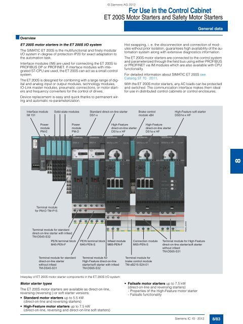
© Siemens AG <strong>2012</strong>For Use in the Control CabinetET 200S Motor Starters and Safety Motor StartersGeneral data■ OverviewET 200S motor starters in the ET 200S I/O systemThe SIMAT<strong>IC</strong> ET 200S is the multifunctional and finely modularI/O system in degree of protection IP20 for exact adaptation tothe automation task.Interface modules (IM) are used for connecting the ET 200S toPROFIBUS DP or PROFINET. If interface modules with integratedS7-CPU are used, the ET 200S can act as a small controlsystem.The ET 200S is designed for combining with a large range of digitaland analog input or output modules, technology modules,IO-Link master modules, pneumatic connections, or motor startersand frequency converters for the control of drives.Device replacement is easy and quick thanks to permanent wiringand automatic re-parameterization.Hot swapping, i. e. the disconnection and connection of moduleswithout prior isolation, guarantees high availability of the automationsystem along with extensive diagnostics information.The ET 200S motor starters are connected to the control systemand parameterized through the field bus using either PROFIBUSor PROFINET via IM modules which are also available with CPUfunctionality.For detailed information about SIMAT<strong>IC</strong> ET 200S see<strong>Catalog</strong> ST 70 · 2011.With the ET 200S motor starters, any AC loads can be protectedand switched. The communication interface makes them idealfor use in distributed control cabinets or control enclosures.Interface moduleIM 151Solid-state modulesStandard direct-on-line starterDS1-xBrake controlmodule xB4High-Feature soft starterDSS1e-x HFPowermodulePM-EPowermodulePM-DHigh-Featuredirect-on-line starterDS1e-x HFHigh-Featuredirect-on-line starterDS1e-x HF8Terminal modulefor PM-D TM-P15Terminal module for standarddirect-on-line starter with infeedTM-DS45-S32PE/N terminal blockM45-PEN-FPE/N terminal blockM45-PEN-SInfeed moduleM65-PEN-FConnection moduleM65-PEN-SNSA0_00459Terminal module for High-Featuredirect-on-line starter/soft starterwithout infeedTM-DS65-S31Terminal module for standarddirect-on-line starterwithout infeedTM-DS45-S31Terminal module forHigh-Feature direct-on-linestarter/soft starter with infeedTM-DS65-S32Terminal module forbrake control moduleTM-xB215-S24-01Interplay of ET 200S motor starter components in the ET 200S I/O systemMotor starter typesThe ET 200S motor starters are available as direct-on-line,reversing (reversing ) or soft starter versions:• Standard motor starters up to 5.5 kW(direct-on-line and reversing starters)• High-Feature motor starters up to 7.5 kW(direct-on-line, reversing and direct-on-line soft starters)• Failsafe motor starters up to 7.5 kW(direct-on-line and reversing starters)- Properties of the High-Feature motor starter- Failsafe functionalitySiemens <strong>IC</strong> <strong>10</strong> · <strong>2012</strong>8/83
© Siemens AG <strong>2012</strong>For Use in the Control CabinetET 200S Motor Starters and Safety Motor StartersGeneral dataTerminal modules are purely mechanical components for accommodatingthe ET 200S I/O modules. The self-assemblingvoltage buses integrated into the terminal modules reduce wiringoutlay to the single infeed (both of auxiliary and load voltage).All modules following on the right are automatically suppliedupon plugging the terminal modules together. The robustdesign and keyed connection technology enables use in harshindustrial conditions.The TM-DS and TM-RS terminal modules are available in variousversions for the Standard motor starters and the High-Featuremotor starters.Terminal modules with the suffix "-S32"• The terminal modules with the suffix "-S32" have connectionterminals for feeding into the integrated 40A/50A power busand connection terminals for the motor connection cable.They are mounted at the beginning (left) of a power bus segment.• To configure a new load group, another "-S32" terminal moduleis plugged in.• The "-S32" terminal modules are supplied with three caps forclosing the power bus contacts on the final terminal module ofa segment.• Optionally expandable with PE/N modulesTerminal modules with the suffix "-S31"• The terminal modules with the suffix "-S31" have only connectionterminals for the motor connection cable. These terminalmodules follow on the right after a "-S32" terminal module.• Optionally expandable with PE/N modulesAll connection terminals of the terminal modules for motor startersare equipped with strong <strong>10</strong> mm² screw terminals.Power modules (page 8/97)PM-D power modules are used for monitoring the two 24 V DCauxiliary voltages for the group of motor starters following on theright or for supplying power to the group of frequency convertersfollowing on the right.TM-P terminal modules for PM-D power module (page 8/98)• Connection by means of screw terminals• Light colored enclosure for visual distinction• Always before the first TM-DS/TM-RSET 200S Safety motor starters with integrated safety technologyThe safety-related, communication-capable ET 200S motorstarters offer the right solution for every safety application. Therange extends from the simple local safety solution through tothe user-friendly version with PROFIsafe, which can be used inconjunction with a safe control system (see "Safety Modules localand PROFIsafe", page 8/<strong>10</strong>2).The safety engineering is an integral part and is therefore prewiredat the factory.The ET 200S Safety Motor Starter Solutions comprise:• Safety modules (page 8/<strong>10</strong>3)• Standard motor starters (page 8/90)• High-Feature motor starters (page 8/93)• Failsafe motor starters (page 8/99)System configuration with ET 200S motor startersWhen constructing an ET 200S station with motor starters a distinctioncan be made between the following configurations:• Conventional ET 200S motor starter solution consisting of:- PM-D module- Standard motor starter or High-Feature motor starter• ET 200S Safety Motor Starter Solution local (see page 8/<strong>10</strong>2)• ET 200S Safety Motor Starter Solutions PROFIsafe(see page 8/<strong>10</strong>6)SIRIUS motor starter block library for SIMAT<strong>IC</strong> PCS 7With the SIRIUS motor starter PCS 7 block library, SIRIUSET 200S motor starters (direct and reversing starters, direct-onlinesoft starters) can be easily and simply integrated into theSIMAT<strong>IC</strong> PCS 7 process control system. The SIRIUS motorstarter PCS 7 block library contains the diagnostics and driverconcept of SIMAT<strong>IC</strong> PCS 7 corresponding diagnostics anddriver blocks as well as the elements required for operation andmonitoring (symbols and faceplates), see Chapter 14 "Parametrization,Configuration and Visualization with SIRIUS".Configuration tool for ET 200S stationThe "SIMAT<strong>IC</strong> Selection Tool" enables the fast and accurate selectionof SIMAT<strong>IC</strong> hardware. It is available as a configurator inthe Siemens <strong>Industry</strong> Mall free of charge. Set your stations (e.g.S7-1200, S7-300, S7-400, S7-400H) together and select the desireddistributed I/O (for B. ET 200S, ET 200pro). You can transferthe Parts Lists you received to the <strong>Industry</strong> Mall shopping cartand place your order quickly, conveniently and with no problems.You can find detailed information about the ET 200S system at:www.siemens.com/ET200SHere, you will find a link to the SIMAT<strong>IC</strong> Selection Tool.8Siemens <strong>IC</strong> <strong>10</strong> · <strong>2012</strong>8/85
For Use in the Control CabinetET 200S Motor Starters and Safety Motor StartersGeneral data© Siemens AG <strong>2012</strong>8SIMAT<strong>IC</strong> ET 200SSIMAT<strong>IC</strong> ET 200SStandard motor starters High-Feature motor starters 1)Device functions (firmware features)Slave on the busFieldbus ✓ Dependent on the interface moduleParameterizationPROFIBUS / PROFINET data records -- ✓Parameterization using data record start -- ✓DiagnosticsAcyclic through data records -- ✓Support of diagnostics alarm✓Diagnostics using PROFIBUS/PROFINET -- ✓ See manualProcess imageProcess image ✓ 3I/3O ✓ 16I/7OAddress area required per module ✓ 4 bits ✓ 2 byteData channelsOperator terminal interface -- ✓ Through moduleMotor Starter ES through local interface -- ✓ Starting end of 2011Motor Starter ES through bus -- ✓ Starting end of 2011Data records (acyclic)Parameterization -- ✓Support for PROFIenergy profile -- ✓ Measuring the motor current and disconnectionin dead timesDiagnostics -- ✓Measured values -- ✓Statistics -- ✓Commands -- ✓Slave pointer -- ✓Logbook -- ✓Device identification -- ✓I&M data -- ✓InputsNumber ✓ Maximum 2, via xB3, xB4, xB6 ✓ Maximum 4, 2 via xB3, xB4, xB6 and2 via module 2DI 24 V DC COM• Of these in the process image -- ✓ 4Input action ✓ End position on left, right ✓ Parameterizable: FlexibleQuick-Stop -- ✓ ParameterizableOutputsNumber ✓ Internal, for controlling the brake moduleOutput action ✓ BrakeBrake output with additional moduleMotor brake voltage: brake module ✓ 24 V DC: xB1/xB3, 500 V DC: xB2/xB4, 400 V AC: xB5/xB6Motor protectionOverload protection ✓ Thermal, range 1:1.3 ✓ Electronic, wide range 1:<strong>10</strong>Overload warning -- Only tripping ✓Short-circuit protection ✓ Circuit breaker ✓Full motor protection --Motor protection response in case of overloadThermal motor model reaction✓ Function is available-- Function not available-- ✓ Parameterizable: disconnection without restart,disconnection with restart, warningAuto reset --Temperature sensor --Emergency start function -- (✓ with 3RK1 903-0CG00 control unit) ✓1) The device functions mentioned apply in full only to the new.-.AB4 starters.8/86 Siemens <strong>IC</strong> <strong>10</strong> · <strong>2012</strong>
© Siemens AG <strong>2012</strong>For Use in the Control CabinetET 200S Motor Starters and Safety Motor StartersGeneral dataSIMAT<strong>IC</strong> ET 200SSIMAT<strong>IC</strong> ET 200SStandard motor starters High-Feature motor starters 1)Device functions (firmware features)Device functionsRepair switch ✓ Rocker switch ✓ Motor Starter ProtectorsMotor starter protector signaling ✓ ✓ ParameterizableCurrent limit monitoring bottom -- ✓ Parameterizable,increment 3.125 %, 18.75 ... <strong>10</strong>0 %Current limit monitoring top -- ✓ Parameterizable,increment 3.125 %, 50 ... 150 % (400 % with thenew .-.AB4 starters)Zero current detection -- ✓ Parameterizable: warning, disconnectionStall protection/disconnecting the blocking current -- ✓ ParameterizableUnbalance ✓ ✓ Parameterizable: warning, disconnectionLoad type -- ✓ Parameterizable: 1- and 3-phaseShutdown class ✓ CLASS <strong>10</strong> ✓ Parameterizable (through ES, DS motor starter)For DS1e-x, RS1e-x: CLASS 5 (<strong>10</strong>A), <strong>10</strong>, 15, 20for DSS1e-x: CLASS 5 (<strong>10</strong>A), <strong>10</strong>Protection against voltage failure ✓ ✓ Parameterizable: Activated/deactivatedLocal diagnostics function using LEDsSwitching state "C-STAT" ✓ Red/green/yellow LEDsGroup fault "SF" ✓ Red LEDsDevice state "DEV<strong>IC</strong>E" -- ✓ Red/green/yellow LEDsAuxiliary switches for enabling circuit of theET 200S – safety technology already integrated(for use up to SIL 3 (IEC 61508) orup to category 4 (ISO 13849-1))-- Failsafe kit needed ✓ Except DSS1e-x (max. category 1 possible)✓ Function is available-- Function not available1) The device functions mentioned apply in full only to the new.-.AB4 starters.8ET 200S StandardET 200S High-Feature motor startersmotor startersDS1-x, RS1-x DS1e-x, RS1e-x DSS1e-xDevice functions (firmware features)Soft starter control functionSoft start function -- ✓Bypass function --Starting time -- ✓ Locally adjustable, not through bus0 ... 20 sRamp-down time -- ✓ Locally adjustable, not through bus0 ... 20 sRamp-down mode -- ✓ Locally adjustable, not through busStarting voltage -- ✓ Locally adjustable, not through bus30 ... <strong>10</strong>0 % of U eStopping voltage -- ✓ Locally adjustable, not through busTrace --✓ Function is available-- Function not availableSiemens <strong>IC</strong> <strong>10</strong> · <strong>2012</strong>8/87
For Use in the Control CabinetET 200S Motor Starters and Safety Motor StartersGeneral data© Siemens AG <strong>2012</strong>■ BenefitsAdvantages through energy efficiencyIdentificationEnergy efficiency consultingaccording toEN 16001RealizationEvaluation<strong>IC</strong>01_00135Overview of the energy management processWe offer you a unique portfolio for industrial energy management,using an energy management system that helps to optimallydefine your energy needs. We split up our industrial energymanagement into three phases – Identification, Evaluationand Realization – and we support you with the appropriate hardwareand software solutions in every process phase.The innovative products of the SIRIUS industrial controls portfoliocan also make a substantial contribution to a plant's energyefficiency (see www.siemens.com/sirius/energysaving).SIMAT<strong>IC</strong> ET 200S motor starters contribute to energy efficiencyas follows:• Energy managementProvision of energy data (current) by bus to higher-level systemsusing PROFIenergy (see "High-Feature Motor Starters",page 8/93)• Elimination of energy consumption in dead times through disconnectionusing PROFIenergy (see "High-Feature MotorStarters", page 8/93)• Current managementAvoidance of current peaks, thus reducing the load on the gridand the mechanical system• Reduced heating of the control cabinetTechnology-reduced inherent power loss as speed-controlleddrive systems, enabling also lower cooling costs (and a morecompact design)8■ ApplicationThe SIMAT<strong>IC</strong> ET 200S motor starters are ideal for the use of severalspatially concentrated distributed drive solutions in whichseveral motors, digital or analog sensors and actuators are addressedby a distributed control cabinet or control box. They areperfectly suited for protecting and switching any AC loads.Application areasThe SIMAT<strong>IC</strong> ET 200S motor starters are suitable for numeroussectors of industry, e. g. machinery and plant engineering orconveying applications.The ET 200S High-Feature motor starters are an excellent choicefor the operation of ventilation systems, pump drives or winches.8/88 Siemens <strong>IC</strong> <strong>10</strong> · <strong>2012</strong>
© Siemens AG <strong>2012</strong>For Use in the Control CabinetET 200S Motor Starters and Safety Motor StartersGeneral data■ Technical specificationsET 200S Standard motor starters ET 200S High-Feature motor startersDS1-x, RS1-x DS1e-x, RS1e-x DSS1e-xMechanics and environmentMotor starters for connection to ET 200S, max. 1) 42 17Mounting dimensions (W x H x D)• Direct-on-line starters mm 45 x (265 + 45) x (120 + 27);(45: PE/N module;27: Auxiliary switch contactorfrom F-Kit)• Reversing starters mm 90 x (265 + 45) x (120 + 27);(45: PE/N module;27: Auxiliary switch contactorfrom F-Kit)Permissible ambient temperature• During operation °C 0 ... +60,From +40 with derating1) Additional limits: Process image, max. design width 2 m.65 x (290 + 45) x (150 + 23);(45: PE/N module; 23: Control module)130 x (290 + 45) x (150 + 23);(45: PE/N module; 23: Control module)0 ... +60With horizontal mounting up to +40• During storage °C -40 ... +70 -40 ... +70• Permissible mounting positions °C Vertical, horizontalVertical, horizontalWith deratingWeight• Direct-on-line/reversing starters incl. terminal module kg 1.0/1.6 1.6/2.2 1• Direct-on-line/reversing starters incl. terminal module1.1/1.8 1.7/2.3 1.1PE/NVibration resistance acc. to IEC 60068-2-6 g 2Shock resistance acc. to IEC 60068-2-27 g/ms Square 5/11Conductor cross-section• Solid mm 2 2 x (1 ... 2.5) 2) ; 2 x (2.5 ... 6) 2) , according to IEC 60947: max. 1 x <strong>10</strong>• Finely stranded with end sleeve mm 2 2 x (1 ... 2.5) 2) ; 2 x (2.5 ... 6) 2)• AWG cables, solid or stranded AWG 2 x (14 ... <strong>10</strong>)Degree of protectionIP20, finger-safe (this also applies to terminal modules on a dismounted motor starter)Mechanical endurance• Motor Starter ProtectorsOperating <strong>10</strong>0 000• Contactors cycles 30 million <strong>10</strong> million --• Contactor with safety functionality (F-Kit) <strong>10</strong> million -- --Electrical specificationsPower consumption• From auxiliary circuit L+/M (U 1 ) mA Approx. 20 Approx. 40• From auxiliary circuit A1/A2 (U 2 ) mA Approx. <strong>10</strong>0 Approx. 1 700Approx. 30(80 ms long),approx. 350 (after 80 ms)Rated operational current for TM-D terminal A 40 50modules I eRated operational voltage U e V 400Approval to DIN VDE 0<strong>10</strong>6 Part <strong>10</strong>1 V Yes, up to 500 Yes, up to 480Approval to CSA and U L V Yes, up to 600 Yes, up to 480Rated operational current I e for motor starters• AC-1/2/3 at 60 °C- At 400 V A 12 16 3 / 8 / 16- At 500 V A 9 11 --• AC-4 at 60 °C- At 400 V A 4.1 9 --Rated short-circuit breaking capacity kA 50 at 400 VPower of induction motors at 500 V kW 5.5 7.5Utilization categoriesAC-1, AC-2, AC-3, AC-4Protective separation between main andV 400, acc. to DIN VDE 0<strong>10</strong>6, Part <strong>10</strong>1auxiliary circuitsPositively-driven operation of contactor relay (NC) Yes --Trip class CLASS <strong>10</strong> ParameterizableCLASS 5 (<strong>10</strong>A), <strong>10</strong>, 15,200.3 ... 3 A: CLASS<strong>10</strong>/<strong>10</strong>A, parameterizable;2.4 ... 8 A: CLASS <strong>10</strong>A2.4 ... 16 A: CLASS <strong>10</strong>AType of coordination Up to 1.6 A: 2Up to 16 A: 2 Up to 16 A: 1Up to 12 A: 1Electrical endurance• Motor Starter Protectors h <strong>10</strong>0 000• Contactors See manual --Permissible switching frequency with a starting 1/h < 80 See manualtime t A = 0.1 s and a relative ON period t OP = 50 %Induction protectionAlready installed2) If two different conductor cross-sections are connected to one clampingpoint, both cross-sections must lie in the range specified. If identical crosssectionsare used, this restriction does not apply.8Siemens <strong>IC</strong> <strong>10</strong> · <strong>2012</strong>8/89
For Use in the Control CabinetET 200S Motor Starters and Safety Motor StartersStandard motor starters© Siemens AG <strong>2012</strong>■ OverviewFunctionality of the Standard motor starters• Basic functionality see "General Data" ➞ "Overview"on page 8/84.• Direct-on-line and reversing starters up to 5.5 kW• Power bus up to 40 A• With circuit breaker and contactor assembly• Integrated isolating function of the circuit breaker• Can be combined with local safety technology for use insafety-related system components with F-Kit andPM-D F modules (see "Accessories" on page 8/113)Device functions (firmware features)See page 8/86 and 8/87.■ Technical specificationsSee page 8/89.■ Selection and ordering data8Induction motor 4-pole at400 V AC,standard output PkWSetting range ofthe electronic releaseADT Order No. Priceper PUPU(UNIT,SET, M)Standard motor starters,with diagnostics, electromechanical, fuseless,expandable with brake control moduleDS1-x direct-on-line starters< 0.06 0.14 ... 0.20 A 3RK1 301-0BB00-0AA2 1 1 unit 42D0.06 0.18 ... 0.25 A 3RK1 301-0CB00-0AA2 1 1 unit 42D0.09 0.22 ... 0.32 A 3RK1 301-0DB00-0AA2 1 1 unit 42D0.<strong>10</strong> 0.28 ... 0.40 A 3RK1 301-0EB00-0AA2 1 1 unit 42D0.12 0.35 ... 0.50 A 3RK1 301-0FB00-0AA2 1 1 unit 42D0.18 0.45 ... 0.63 A 3RK1 301-0GB00-0AA2 1 1 unit 42D0.21 0.55 ... 0.80 A 3RK1 301-0HB00-0AA2 1 1 unit 42D0.25 0.70 ... 1.00 A 3RK1 301-0JB00-0AA2 1 1 unit 42D0.37 0.90 ... 1.25 A 3RK1 301-0KB00-0AA2 1 1 unit 42D0.55 1.1 ... 1.6 A 3RK1 301-1AB00-0AA2 1 1 unit 42D0.75 1.4 ... 2.0 A 3RK1 301-1BB00-0AA2 1 1 unit 42D0.90 1.8 ... 2.5 A 3RK1 301-1CB00-0AA2 1 1 unit 42DDS1-x1.1 2.2 ... 3.2 A 3RK1 301-1DB00-0AA2 1 1 unit 42D1.5 2.8 ... 4.0 A 3RK1 301-1EB00-0AA2 1 1 unit 42D1.9 3.5 ... 5.0 A 3RK1 301-1FB00-0AA2 1 1 unit 42D2.2 4.5 ... 6.3 A 3RK1 301-1GB00-0AA2 1 1 unit 42D3.0 5.5 ... 8.0 A 3RK1 301-1HB00-0AA2 1 1 unit 42D4.0 7 ... <strong>10</strong> A 3RK1 301-1JB00-0AA2 1 1 unit 42D5.5 9 ... 12 A 3RK1 301-1KB00-0AA2 1 1 unit 42DReversing starter RS1-x< 0.06 0.14 ... 0.20 A 3RK1 301-0BB00-1AA2 1 1 unit 42D0.06 0.18 ... 0.25 A 3RK1 301-0CB00-1AA2 1 1 unit 42D0.09 0.22 ... 0.32 A 3RK1 301-0DB00-1AA2 1 1 unit 42D0.<strong>10</strong> 0.28 ... 0.40 A 3RK1 301-0EB00-1AA2 1 1 unit 42D0.12 0.35 ... 0.50 A 3RK1 301-0FB00-1AA2 1 1 unit 42D0.18 0.45 ... 0.63 A 3RK1 301-0GB00-1AA2 1 1 unit 42D0.21 0.55 ... 0.80 A 3RK1 301-0HB00-1AA2 1 1 unit 42D0.25 0.70 ... 1.00 A 3RK1 301-0JB00-1AA2 1 1 unit 42D0.37 0.90 ... 1.25 A 3RK1 301-0KB00-1AA2 1 1 unit 42DRS1-x0.55 1.1 ... 1.6 A 3RK1 301-1AB00-1AA2 1 1 unit 42D0.75 1.4 ... 2.0 A 3RK1 301-1BB00-1AA2 1 1 unit 42D0.90 1.8 ... 2.5 A 3RK1 301-1CB00-1AA2 1 1 unit 42D1.1 2.2 ... 3.2 A 3RK1 301-1DB00-1AA2 1 1 unit 42D1.5 2.8 ... 4.0 A 3RK1 301-1EB00-1AA2 1 1 unit 42D1.9 3.5 ... 5.0 A 3RK1 301-1FB00-1AA2 1 1 unit 42D2.2 4.5 ... 6.3 A 3RK1 301-1GB00-1AA2 1 1 unit 42D3.0 5.5 ... 8.0 A 3RK1 301-1HB00-1AA2 1 1 unit 42D4.0 7 ... <strong>10</strong> A 3RK1 301-1JB00-1AA2 1 1 unit 42D5.5 9 ... 12 A 3RK1 301-1KB00-1AA2 1 1 unit 42DPS*PG8/90 Siemens <strong>IC</strong> <strong>10</strong> · <strong>2012</strong>* You can order this quantity or a multiple thereof.Illustrations are approximate
© Siemens AG <strong>2012</strong>For Use in the Control CabinetET 200S Motor Starters and Safety Motor StartersStandard terminal modules■ OverviewTerminal module TM-DS, TM-RSMore information see also "General Data" ➞ "Overview" ➞ section"Power Supply through Terminal Modules" on page 8/84 onwards.• "–S32" version with supply terminals: 2 x 3 x <strong>10</strong> mm² screw terminalsfor power bus and motor feeder• "–S31" version without supply terminals: 1 x 3 x <strong>10</strong> mm² screwterminals for motor feeder• Optionally expandable with PE/N modules (see "Accessories"of page 8/115)• Applies only to Standard motor starters: For applications withhigh motor currents (> 6.3 A) or high ambient temperatures(> 40 °C) it is recommended to use the DM-V15 distance module(see "Accessories" on page 8/114) between two DS1-xmotor starters.■ Technical specificationsTM-DS45 and TM-DS65/TM-FDS65 terminal moduleTM-DS45TM-DS65/TM-FDS65Dimensions• Mounting dimensions (W x H x D) mm 45 x 264 x <strong>10</strong>0 65 x 290 x <strong>10</strong>0• Height with PE/N terminal block mm 306 332• Depth with motor starter mm 127 150• Depth with motor starter and F-Kit (safety technology) mm 152 --• Depth with motor starter and 2DI control module mm -- 173Rated voltages, currents and frequencies for the power bus• Rated insulation voltage U i V 690• Rated operational voltage U e V AC 500• Rated impulse withstand voltage U imp kV 6• Rated operational current I e A 40 50• Rated frequency Hz 50/60Conductor cross-sections• Solid mm 2 2 x (1 ... 2.5) 1) or2 x (2.5 ... 6) 1)• Finely stranded with end sleeve mm 2 1 x <strong>10</strong> or2 x (1 ... 2.5 ) 1) or2 x (2.5 ... 6) 1)according to IEC 60947• AWG cables, solid or stranded AWG 2 x (14 ... <strong>10</strong>)• With additional three-phase feeder terminal if required- Solid or stranded mm 2 1 x 2.5 ... 25- Finely stranded with end sleeve mm 2 1 x 2.5 ... 25- AWG cables, solid or stranded AWG 1 x 12 ... 4Wiring• Required tool Standard screwdriver size 2 and Pozidriv 2• Tightening torque Nm 2.0 ... 2.51) If two different conductor cross-sections are connected to one clampingpoint, both cross-sections must lie in the range specified. If identical crosssectionsare used, this restriction does not apply.8TM-RS90 and TM-RS130/TM-FRS130 terminal moduleTM-RS90TM-RS130/TM-FRS130Dimensions• Mounting dimensions (W x H x D) mm 90 x 264 x <strong>10</strong>0 130 x 290 x <strong>10</strong>0• Height with PE/N mm 306 332• Depth with motor starter mm 127 150• Depth with motor starter and F-Kit (safety technology) mm 152 --• Depth with motor starter and 2DI control module mm -- 173Rated voltages, currents and frequencies for the power bus• Rated insulation voltage U i V 690• Rated operational voltage U e V AC 500• Rated impulse withstand voltage U imp kV 6• Rated operational current I e A 40 50• Rated frequency Hz 50/60Siemens <strong>IC</strong> <strong>10</strong> · <strong>2012</strong>8/91
8For Use in the Control CabinetET 200S Motor Starters and Safety Motor StartersStandard terminal modules© Siemens AG <strong>2012</strong>Conductor cross-sections• Solid mm 2 2 x (1 ... 2.5) 1) or 2 x (2.5 ... 6) 1)• Finely stranded with end sleeve mm 2 1 x <strong>10</strong> or2 x (1 ... 2.5 ) 1) or 2 x (2.5 ... 6) 1)according to IEC 60947• AWG cables, solid or stranded AWG 2 x (14 ... <strong>10</strong>)• With additional three-phase feeder terminal if required- Solid or stranded mm 2 1 x 2.5 ... 25- Finely stranded with end sleeve mm 2 1 x 2.5 ... 25- AWG cables, solid or stranded AWG 1 x 12 ... 4Wiring• Required tool Standard screwdriver size 2 and Pozidriv 2• Tightening torque Nm 2.0 ... 2.51) If two different conductor cross-sections are connected to one clampingpoint, both cross-sections must lie in the range specified. If identical crosssectionsare used, this restriction does not apply.■ Selection and ordering dataTM-RS90TM-RS130/TM-FRS130Version DT Order No. Priceper PUPU(UNIT,SET, M)PS*PGTerminal modules for Standard motor startersTM-DS45-S32for DS1-x direct-on-line starterswith incoming power for bus connectionincluding three caps for terminating the power busA 3RK1 903-0AB00 1 1 unit 42D3RK1 903-0AB00TM-DS45-S31for DS1-x direct-on-line starterswithout incoming power bus connectionA 3RK1 903-0AB<strong>10</strong> 1 1 unit 42D3RK1 903-0AB<strong>10</strong>TM-RS90-S32for RS1-x reversing starterswith incoming power bus connectionincluding three caps for terminating the power busA 3RK1 903-0AC00 1 1 unit 42D3RK1 903-0AC00TM-RS90-S31for RS1-x reversing starterswithout incoming power bus connectionA 3RK1 903-0AC<strong>10</strong> 1 1 unit 42D8/92 Siemens <strong>IC</strong> <strong>10</strong> · <strong>2012</strong>* You can order this quantity or a multiple thereof.Illustrations are approximate
© Siemens AG <strong>2012</strong>For Use in the Control CabinetET 200S Motor Starters and Safety Motor StartersHigh-Feature motor starters■ OverviewFunctionality of the High-Feature motor starters• Basic functionality see "General Data" ➞ "Overview"on page 8/84.• Direct-on-line, reversing or soft starter up to 7.5 kW• With wide range in 3 setting ranges, with 0.3 to 3 A,2.4 up to 8 A, 2.4 to 16 A available• With combination of starter circuit breaker, electronic overloadprotection (parameterizable), and contactor or soft starter• Power bus up to 50 A• Upper and lower current limits for plant and process monitoring• Motor stall protection, zero current detection and asymmetrydetection integrated• The actual motor current is measured and transmitted fordiagnostics in the cyclic process image• Control of the motor starter from the control system and extensivediagnostics status via the cyclic process image• Optional digital inputs available in the cyclic process imageand flexibly assignable with functions for adaptation to allapplications• Detection of the switching state of the starter circuit breaker viaaux. switches and of the contactor via current evaluation• Integrated isolating function using starter circuit breakers• Local safety engineering possible (without failsafe kit in thecase of the HF starter, because the function of the failsafe kit isalready integrated)• Front-mounting 2DI LC COM control module for 2 moreparameterizable digital inputs• Optional "Motor Starter ES" software for easy commissioningand diagnostics - from 11/2011 also for the new .-.AB4 -Starteravailable (see Chapter 14 "Parametrization, Configuration andVisualization with SIRIUS")• PROFIenergy capable (only with the new .-.AB4 -starters)• Supplying the motor current in PROFIenergy format- Switching off during dead times• All acyclic services DPV1 supported by PROFIBUS andPROFINET (only with the new .-.AB4 -starters)- Changing of parameters during operation, e.g. the ratedoperational current- Reading and writing acyclic data for exact diagnostics of theunit or process and for analysis of the plant statusSelective protection concept forET 200S High-Feature motor startersAs a result of the selective protection concept (separate trippingof short circuit and overload) with solid-state overload evaluation,additional advantages are realized on the High-Feature motorstarters – advantages which soon make themselves positivelyfelt particularly in manufacturing processes with high plantstoppage costs:• Only two versions up to 7.5 kW – hence little order variance andstock keeping• All settings can be parameterized by bus – hence fullTIA capability• Separate signaling of overload and short circuit – enablesselective diagnostics• Overload can be acknowledged by remote reset – ideal forhighly automated plants• Current asymmetry monitoring – complete monitoring of themotor• Stall protection – complete monitoring of the motor• Emergency start function in case of overload – operation is possiblein an emergency• Current value transmission via bus – monitoring of the application• Current limit monitoring• Trip class can be parameterized – overload trip can be adaptedto the application• Type of coordination "2" – still functional after short circuit withmagnitude of 50 kA• Very high contact enduranceET 200S High-Feature motor starter: DS1e-x direct-on-line starter(innovated .-.AB4 starters)ET 200S High-Feature motor starter: DS1e-x direct-on-line soft starter(innovated .-.AB4 starter)ET 200S High-Feature motor starter: Reversing starter (reversing starter)RS1e-x (innovated .-.AB4 -Starter)8Siemens <strong>IC</strong> <strong>10</strong> · <strong>2012</strong>8/93
© Siemens AG <strong>2012</strong>For Use in the Control CabinetET 200S Motor Starters and Safety Motor Starters8High-Feature motor startersPROFIenergy for ET 200S High-Feature motor starters 1)Increasing energy prices, far-reaching ecological problemsworldwide and the threat of climate change make it necessaryfor you to be more conscious about your use of energy.Active and effective energy management is possible withPROFIenergy.PROFIenergy is a manufacturer-independent profile onPROFINET, which can be used by all manufacturers, has beenstandardized by PNO 1) and supports the shut-down of electricaldevices during dead times and the read-out of measured values.The ET 200S HF motor starter supplies the motor current inPROFIenergy format and switches off during dead times.All acyclic services DPV1 supported by PROFIBUS andPROFINET (only with the new .-.AB4 -starters)Thanks to the acyclic services, the ET 200S HF motor startersnow offer plenty of diagnostics data via data records. There areextensive new options for reading out data from the motor starterfor device, system or process monitoring. The motor starter isequipped internally with three logbooks for device faults, motorstarter trips and events, which are issued with a time stamp.These logbooks can be read out of the motor starter on demandat any time and provide the plant operator with plenty of informationabout the state of his plant and process which he can use tocarry out improvements.With the slave pointer and statistical data functions it is possibleto read out, for example, the maximum internal current values orthe number of motor starter connection operations. This enablesprocess deviations to be monitored or commissioning to be optimized.Statistical data or measured values make plant monitoring easyfor the user.The device diagnostics data record contains details of all thestates of the motor starter, the device configuration and the communicationas a basis for central device and plant monitoring.■ Technical specificationsSee page 8/89.The Installation and Maintenance Functions (I&M) store, firstly,information (I&M) about the modules used in the motor starterand, secondly, data (I&M) that can be defined during configuration,e.g. location designations. I&M functions are used for fortroubleshooting faults and localizing changes in hardware at aplant or checking the system configuration.Supported data records:• DS 0 S7-V1 system diagnostics (S7 diagnostics alarm)• DS 72, 73, 75 logbooks, device faults, trips, events• DS 92 device diagnostics• DS 93 command• DS 94 measured values• DS 95 statistics• DS 96 slave pointer• DS <strong>10</strong>0 device identification• DS 131 device parameters• DS 134 maintenance• DS 165 comment• DS 226 PROFIenergy technology function• DS 231 I&M 0 (= device identification)• DS 232 I&M 1 (= equipment identifier)• DS 233 I&M 2 (= installation)• DS 234 I&M 3 (= description)Device functions (firmware features)See page 8/86 and 8/87.1) In the PNO (PROFIBUS Nutzerorganisation e. V. - PROFIBUS User Organization),manufacturers and users have come together to agree on the standardizedcommunication technologies PROFIBUS and PROFINET.8/94 Siemens <strong>IC</strong> <strong>10</strong> · <strong>2012</strong>
■ Selection and ordering dataHigh-Feature motor starters in previous design (".-.AA4 starters")Setting range ofthe electronic release© Siemens AG <strong>2012</strong>For Use in the Control CabinetET 200S Motor Starters and Safety Motor StartersDT Order No. Priceper PUHigh-Feature motor startersPU(UNIT,SET, M)AHigh-Feature motor starters,with diagnostics, solid-state overload protection,fuseless, expandable with brake control moduleDS1e-x direct-on-line starters0.3 ... 3 A 3RK1 301-0AB<strong>10</strong>-0AA4 1 1 unit 42D2.4 ... 8 A 3RK1 301-0BB<strong>10</strong>-0AA4 1 1 unit 42D2.4 ... 16 A 3RK1 301-0CB<strong>10</strong>-0AA4 1 1 unit 42DRS1e-x reversing starters0.3 ... 3 A 3RK1 301-0AB<strong>10</strong>-1AA4 1 1 unit 42D2.4 ... 8 A 3RK1 301-0BB<strong>10</strong>-1AA4 1 1 unit 42D2.4 ... 16 A 3RK1 301-0CB<strong>10</strong>-1AA4 1 1 unit 42DDirect-on-line soft starter DSS1e-xDS1e-x0.3 ... 3 A 3RK1 301-0AB20-0AA4 1 1 unit 42D2.4 ... 8 A 3RK1 301-0BB20-0AA4 1 1 unit 42D2.4 ... 16 A 3RK1 301-0CB20-0AA4 1 1 unit 42DPS*PGHigh-Feature motor starters in fully innovated design (".-.AB4 starters") 1)Setting range ofthe electronic releaseDT Order No. Priceper PUPU(UNIT,SET, M)AHigh-Feature motor starters,with diagnostics, solid-state overload protection,fuseless, expandable with brake control moduleDS1e-x direct-on-line starters0.3 ... 3 A 3RK1 301-0AB<strong>10</strong>-0AB4 1 1 unit 42D2.4 ... 8 A 3RK1 301-0BB<strong>10</strong>-0AB4 1 1 unit 42D2.4 ... 16 A 3RK1 301-0CB<strong>10</strong>-0AB4 1 1 unit 42DRS1e-x reversing starters0.3 ... 3 A 3RK1 301-0AB<strong>10</strong>-1AB4 1 1 unit 42D2.4 ... 8 A 3RK1 301-0BB<strong>10</strong>-1AB4 1 1 unit 42D2.4 ... 16 A 3RK1 301-0CB<strong>10</strong>-1AB4 1 1 unit 42DDirect-on-line soft starter DSS1e-xDS1e-x0.3 ... 3 A 3RK1 301-0AB20-0AB4 1 1 unit 42D2.4 ... 8 A 3RK1 301-0BB20-0AB4 1 1 unit 42D2.4 ... 16 A 3RK1 301-0CB20-0AB4 1 1 unit 42D1) When a device is replaced, the innovated motor starter will behave like theprevious motor starter, i.e. it will run in DPV0 mode.PS*PG8* You can order this quantity or a multiple thereof.Illustrations are approximateSiemens <strong>IC</strong> <strong>10</strong> · <strong>2012</strong>8/95
8For Use in the Control CabinetET 200S Motor Starters and Safety Motor StartersHigh-Feature terminal modules© Siemens AG <strong>2012</strong>■ OverviewTerminal module TM-DS, TM-RSMore information see also "General Data" ➞ "Overview" ➞ section"Power Supply through Terminal Modules" on page 8/84 onwards.• "–S32" version with incoming connection: 2 x 3 x <strong>10</strong> mm² screwterminals for power bus and motor feeder• "–S31" version without incoming connection: 1 x 3 x <strong>10</strong> mm²screw terminals for motor feeder• Optionally expandable with PE/N modules (see "Accessories")■ Technical specificationsSee page 8/91.■ Selection and ordering dataVersion DT Order No. Priceper PUPU(UNIT,SET, M)PS*PGTerminal modules for High-Feature motor startersTM-DS65-S32for DS1e-x and DSS1e-x direct-on-line starterswith incoming power bus connection including threecaps for terminating the power busTM-DS65-S31for DS1e-x and DSS1e-x direct-on-line starterswithout incoming power bus connectionTM-RS130-S32for RS1e-x reversing starterswith incoming power bus connection including threecaps for terminating the power busTM-RS130-S31for RS1e-x reversing starters3RK1 903-0AK00Without incoming power bus connectionA 3RK1 903-0AK00 1 1 unit 42DA 3RK1 903-0AK<strong>10</strong> 1 1 unit 42DA 3RK1 903-0AL00 1 1 unit 42DA 3RK1 903-0AL<strong>10</strong> 1 1 unit 42D8/96 Siemens <strong>IC</strong> <strong>10</strong> · <strong>2012</strong>* You can order this quantity or a multiple thereof.Illustrations are approximate
© Siemens AG <strong>2012</strong>For Use in the Control CabinetET 200S Motor Starters and Safety Motor StartersPower modules■ Overview• Disconnection of a complete group of motor starters is possiblewithout any additional outlay (safety category 1according to ISO 13849-1)• PM-D power modules are plugged onto the TM-P15 terminalmodules. (A PM-D power module must be followed by at leastone motor starter or one frequency converter.)PM-D power modules are used for monitoring the two 24 V DCauxiliary voltages for the group of motor starters following on theright or for supplying power to the group of frequency convertersfollowing on the right. The voltage is fed in through TM-D terminalmodules to the self-assembling potential bars.A voltage failure is signaled through PROFIBUS diagnostics tothe higher-level master. Additional LEDs inform locally about thestatus of the auxiliary voltages.The separation of auxiliary voltages for signal checkback andpower section actuation enables the entire group to be shutdown while maintaining the diagnostics capability.■ Technical specificationsRated control supply voltage U sup to 60 °CRated operational current I e• Recommended short-circuitprotectionPM-D power modules3RK1 903-0BA00V 20.4 ... 28A <strong>10</strong>• Melting fuse A <strong>10</strong>• Miniature circuit breaker A <strong>10</strong>, tripping characteristic BPower consumption from the backplanemA ≤ <strong>10</strong>busSupply of• Motor startersYes• Frequency convertersYes• Motor starters for safety technology No• Solid-state modulesNo•Ex(i) modulesNoAlarmsNoneDiagnostics functionsYes• System fault/device faultRed "SF" LED• Monitoring the control supply voltage Green "PWR" LEDfor solid-state modules U 1• Monitoring the control supply voltage Green "CON" LEDfor contactors U 2• Diagnostics information can be read YesoutConductor cross-sections• Flexible with end sleeve mm 2 1.5• Rigid mm 2 2.5Mounting dimensions (W x H x D) mm 15 x 195.5 x 117.58■ Selection and ordering dataVersion DT Order No. Priceper PUPU(UNIT,SET, M)PS*PGPower modulesPM-D power modulesfor 24 V DC with diagnosticsA 3RK1 903-0BA00 1 1 unit 42D3RK1 903-0BA00* You can order this quantity or a multiple thereof.Illustrations are approximateSiemens <strong>IC</strong> <strong>10</strong> · <strong>2012</strong>8/97
8For Use in the Control CabinetET 200S Motor Starters and Safety Motor StartersPower module terminal modules© Siemens AG <strong>2012</strong>■ OverviewTerminal module for power moduleFor feeding load and sensor voltage to the self-assembling potentialbars of the Standard motor starters, High-Feature motorstarters and frequency converters. Power modules for voltagemonitoring are plugged onto TM-P modules.TM-P modules can be used any number of times within theET 200S. A power module must always be plugged upstreamfrom the first motor starter/frequency converter.■ Selection and ordering dataVersion DT Order No. Priceper PUPU(UNIT,SET, M)PS*PGTerminal module for power moduleTM-P15 S27-01 terminal modulesfor PM-D power moduleA 3RK1 903-0AA00 1 1 unit 42D3RK1 903-0AA008/98 Siemens <strong>IC</strong> <strong>10</strong> · <strong>2012</strong>* You can order this quantity or a multiple thereof.Illustrations are approximate
© Siemens AG <strong>2012</strong>For Use in the Control CabinetET 200S Motor Starters and Safety Motor StartersET 200S Failsafe motor starters■ OverviewET 200S Failsafe motor starters F-DS1e-x direct-on-line startersThe Failsafe motor starter has been developed on the basis ofthe High-Feature motor starter (.-.AA4 starter). It differs in that, inaddition to a motor starter protector and contactor assembly, asafe solid-state evaluation circuit is installed for error detectionpurposes which makes the motor starter failsafe.If the contactor to be switched fails in an EMERGENCY-STOPcase, the evaluation electronics detects a fault and opens themotor starter protector in the motor starter through a shunt releasein a failsafe manner. The second redundant shutdowncomponent is therefore no longer a main contactor, as it is generallythe case, but the motor starter protector installed in themotor.All functions of the High-Feature starter are already integratedThe new failsafe motor starters are characterized by easy,space-saving assembly as well as minimal wiring outlay. Like theHigh-Feature starters, the Failsafe motor starters have a switchingcapacity of up to 7.5 kW (16 A) which is achieved with justtwo motor starter versions. Another important feature is the highavailability due to the high short-circuit strength (type of coordination"2").UseThe Failsafe motor starter is predestined for use in combinationwith PROFIsafe (see connection diagram "ET 200S Safety MotorStarter Solution PROFIsafe with Failsafe Motor Starters" onpage 8/<strong>10</strong>7). Another field of application is in combination withASIsafe or safety relays (see example 2 on page 8/<strong>10</strong>5).High degree of flexibility with safety technologyPROFIsafe solution with PM-D F PROFIsafeIn EMERGENCY-STOP applications, the Failsafe motor startersare selectively switched off through the upstreamPM-D F PROFIsafe safety module. For each safety module,six switch-off groups can be formed. In the first delivery stage,the failsafe freely-programmable logic of the SIMAT<strong>IC</strong> controlleris used to interface with the relevant Failsafe sensor technology.The interface between PROFIsafe and installations that use conventionalsafety technologies is implemented through theF-CM Failsafe contact multiplier with four floating contacts.Solution local with PM-D FX1Failsafe motor starters with safety relay (Version 1) or ASIsafe(Version 2, see example 2 on page 8/<strong>10</strong>5):Signals with relevance for safety can be input to ET 200S througha PM-D F X1 infeed terminal module through the enabling circuitsof the AS-i Safety Monitor or the safety relay to control theFailsafe motor starters which then selectively switch off thedownstream motors.■ BenefitsAdvantages over conventional safety technology• Significant savings in components (less hardware)• Less mounting and installation work• Motor starters are failsafe and offer high availability8■ Technical specificationsF-DS1e-x direct-on-line starters/F-RS1e-x reversing startersF-DS1e-x direct-on-line startersDimensionsDimensions (W x H x D) mm 65 x 290 x 150(incl. terminal module)Height with PE/N module mm 332Depth with 2DI control module (not safe) mm 173Module-specific specificationsType of coordinationType 2 up to I e ≤ 16 A at 400 VInternal power supply U1 (from PM-D F/PM-DF X1)Maximum achievable safety class• According to IEC 62061 SIL 3• According to DIN VDE 0801Shutdown class 6 (AK6)• According to ISO 13849-1 Category 4Safety characteristicsLow demandPFD AVG (<strong>10</strong>a)• Test interval 3 months 3.5 x <strong>10</strong> -5• Test interval 6 months 8.0 x <strong>10</strong> -5High demand/continuous modePFH• Test interval 3 months 1/h 8.1 x <strong>10</strong> -<strong>10</strong>• Test interval 6 months 1/h 1.8 x <strong>10</strong> -9Proof-test interval Years <strong>10</strong>F-RS1e-x reversing starters130 x 290 x 150(incl. terminal module)Siemens <strong>IC</strong> <strong>10</strong> · <strong>2012</strong>8/99
For Use in the Control CabinetET 200S Motor Starters and Safety Motor StartersET 200S Failsafe motor starters© Siemens AG <strong>2012</strong>8Voltages, currents, potentialsSwitching capacityAAAF-DS1e-x direct-on-line startersUp to 7.5 kW at 400 V AC in three setting ranges• 0.3 ... 3• 2.4 ... 8• 2.4 ... 16F-RS1e-x reversing startersStatus, alarms, diagnosticsStatus displaySF, DEV<strong>IC</strong>E and C-STAT, SG1 ... SG6Diagnostics functions• Group fault displayRed LED (SF)• Diagnostics information can be read outAvailableControl circuitsRated operational voltage for electronics U 1 V DC 24 (20.4 ... 28.8) 24 (21.6 ... 26.4)Reverse polarity protection for electronics U 1YesRated operational voltage for contactor U 2 V DC 24 (20.4 ... 28.8)Reverse polarity protection for contactor U 2YesPower consumption• From electronics supply U 1 mA Approx. 40 Approx. <strong>10</strong>0• From contactor supply U 2-Pickup A 1.7 (for 80 ms) ---Hold mA max. 350 --• From SG1 up to 6- Pickup mA 250 (for 200 ms)-Hold mA max. 55• Test function of the shunt release/starter circuit breaker (50 ms) A Approx. 1.5from U 1• From the backplane bus mA Approx. 20Main circuitRated operational voltage U e• Acc. to IEC 60947-1, VDE 0<strong>10</strong>6, Part <strong>10</strong>1 V AC 500• Protective separation between main and auxiliary circuits V 400• According to UL, CSA V AC 600Rated insulation voltage U i V AC 500Rated impulse withstand voltage U imp kV 6Rated frequency Hz 50/60■ Selection and ordering dataSetting range ofthe electronic releaseDT Order No. Priceper PUPU(UNIT,SET, M)AET 200S Failsafe motor startersF-DS1e-x direct-on-line startersFailsafe direct-on-line starters up to 7.5 kW at 400 V ACMechanically switchingSolid-state UE protection• 0.3 ... 3 A 3RK1 301-0AB13-0AA4 1 1 unit 42D• 2.4 ... 8 A 3RK1 301-0BB13-0AA4 1 1 unit 42D• 2.4 ... 16 A 3RK1 301-0CB13-0AA4 1 1 unit 42DF-DS1e-xdirect-on-linestartersF-RS1e-x reversing startersFailsafe reversing starters up to 7.5 kW at 400 V ACMechanically switchingSolid-state UE protection, fuseless• 0.3 ... 3 A 3RK1 301-0AB13-1AA4 1 1 unit 42D• 2.4 ... 8 A 3RK1 301-0BB13-1AA4 1 1 unit 42D• 2.4 ... 16 A 3RK1 301-0CB13-1AA4 1 1 unit 42DPS*PG8/<strong>10</strong>0 Siemens <strong>IC</strong> <strong>10</strong> · <strong>2012</strong>* You can order this quantity or a multiple thereof.Illustrations are approximate
© Siemens AG <strong>2012</strong>For Use in the Control CabinetET 200S Motor Starters and Safety Motor StartersFailsafe terminal modules■ Selection and ordering dataVersion DT Order No. Priceper PUPU(UNIT,SET, M)PS*PGTerminal modules for Failsafe motor startersTM-FDS65-S32-01/S31-01 terminal modulesfor F-DS1e-x direct-on-line starterswith coding• With incoming power bus connection(TM-FDS65-S32-01)• Without incoming power bus connection(TM-FDS65-S31-01)TM-FRS130-S32-01/S31-01 terminal modulesfor F-RS1e-x reversing starterwith coding• With incoming power bus connection(TM-FRS130-S32-01)• Without incoming power bus connection(TM-FRS130-S31-01)A 3RK1 903-3AC00 1 1 unit 42DA 3RK1 903-3AC<strong>10</strong> 1 1 unit 42DA 3RK1 903-3AD00 1 1 unit 42DA 3RK1 903-3AD<strong>10</strong> 1 1 unit 42D8* You can order this quantity or a multiple thereof.Illustrations are approximateSiemens <strong>IC</strong> <strong>10</strong> · <strong>2012</strong>8/<strong>10</strong>1
8For Use in the Control CabinetET 200S Motor Starters and Safety Motor StartersSafety modules local and PROFIsafe© Siemens AG <strong>2012</strong>■ OverviewET 200S Safety Motor Starter Solutions local/PROFIsafeThe ET 200S Safety Motor Starter Solutions are preferred in allproduction and process automation fields in which the enhancementof plant availability and flexibility plays a key role.• ET 200S Safety Motor Starter Solutions local are preferredfrom the safety technology point of view for locally restrictedsafety applications. These motor starters are not dependenton a safe control system.• ET 200S Safety Motor Starter Solutions PROFIsafe, on theother hand, are often found in safety applications of the morecomplex type that are interlinked. In this case a safe controlsystem is used with the PROFINET or PROFIBUS bus systemswith the PROFIsafe profile.The ET 200S Safety Motor Starter Solutions comprise:• Safety modules (page 8/<strong>10</strong>3)• Standard motor starters (page 8/90)• High-Feature motor starters (page 8/93)• Failsafe motor starters (page 8/99)With the ET 200S Solutions safety motor starters there is no complicatedand hence cost-intensive configuring and wiring comparedto the conventional safety systems. The ET 200S SafetyMotor Starter Solutions are designed for Category 4 accordingto ISO 13849-1 or SIL 3 IEC 62061.They enable the use of safety-oriented direct-on-line starters orreversing starters in the SIMAT<strong>IC</strong> ET 200S distributed I/O systemon PROFINET or PROFIBUS. The fine modular architecture of thesystem permits optimum imaging of machine or plant applications.Within an ET 200S station the Safety motor starters Solutions canalso be combined with Standard motor starters or High-Featuremotor starters without safety functions or the SIMAT<strong>IC</strong>ET 200S FC frequency converters up to max. 4 kW and up toCategory 3 according to ISO 13849-1 or SIL 2 according toIEC 62061.ET 200S Safety Motor Starter Solution localSafety modulePM-D F1Standarddirect-on-linestarter DS1-xSafety modulePM-XSafety modulePM-D F2High-Featuredirect-on-linestarter DS1e-xSafety modulePM-XTerminal modulefor safety module PM-XInterface moduleIM 151NSA0_00434aTerminal modulefor safety modulePM-D F1/2Auxiliary switch ofthe failsafe equipment fordirect-on-line starterF-Kit 1Terminal module for direct-on-linestarter with supply connectionTM-DS45-S32Terminal modulefor safety modulePM-D F1/2Terminal modulefor safety module PM-XPE/N terminal blockwithout supply connectionM65-PEN-STerminal modulefor direct-on-line starterwithout supply connectionTM-DS65-S31PE/N terminal blockwith supply connectionM65-PEN-FTerminal modulefor direct-on-line starterwithout supply connectionTM-DS45-S31Terminal modulefor direct-on-line starterwith TM-DS65-S32supply connectionInterplay of ET 200S Safety Motor Starter Solutions local components8/<strong>10</strong>2 Siemens <strong>IC</strong> <strong>10</strong> · <strong>2012</strong>
© Siemens AG <strong>2012</strong>For Use in the Control CabinetET 200S Motor Starters and Safety Motor StartersSafety modules local and PROFIsafeComponents for ET 200S Safety Motor Starter Solution localThe ET 200S Safety Motor Starter Solutions local comprise:Version 1 (see example 1 on page 8/<strong>10</strong>5):• Safety modules PMD F1 ... 5• PM-X module• Standard motor starter or High-Feature motor starterVersion 2 (see example 2 on page 8/<strong>10</strong>5):• PM-D FX1 safety module• Failsafe motor startersFunctionality of the ET 200S Safety Motor Starter Solutions local• For use of Standard, High-Feature or Failsafe motor starters insystems with safety categories 2 to 4(according to ISO 13849-1)• Can also be used in combination with external safety relays• Can also be used to activate external safety systems• No complex wiring for conventional safety technology• Safety module available for function-monitored and automaticstarting• Safety module available for Stop category 0 and 1• Safety module for monitoring the auxiliary voltages for motorstarters• Safety modules can be plugged into the TM-PF30 terminalmodulesWith Safety motor starters Solutions local the highest safety categorycan be reached according to ISO 13849-1 and IEC 62061.They can thus be used for evaluation of EMERGENCY-STOP circuitsor for monitoring protective doors and also for time-delayeddisconnections. With the contact multiplier the safety-relevantsignals can also be made available to external systems.All standard safety applications can be covered through combinationof different TM-PF30 terminal modules. Needless to say,ET 200S motor starters can also be used in conjunction withexternal safety relays or with ASIsafe.Safety motor starter Solutions local reduce wiring by up to 80 %compared to conventional safety systems with local safety applications.With the Safety motor starters Solutions local it is easy to installseveral safety circuits. The safety sensors are connected directlyand locally to the safety modules. These safety modules performthe work of the otherwise obligatory safety relays and safely shutdown the downstream motor starters in accordance with thefunction selected. The crosslinks required for this are already integratedin the system and need no additional wiring. All signalsfrom the safety modules are automatically relayed as diagnosticsignals, e.g. in the event of crossover in the EMERGENCY-STOPcircuit.The safety module evaluates the signal state of the connectedsafety sensors and, using the integrated safety relays, shutsdown the group(s) of downstream motor starters. The shutdownfunction is monitored by the module, and the auxiliary voltageslikewise.Safety-relevant system signals, e.g. caused by an actuatedEMERGENCY-STOP switch or a missing auxiliary voltage, areautomatically generated and notified to the interface module.The latter assigns an unambiguous ID to the fault. Using thePROFIBUS DP diagnostics block, faults of this type can be identifiedand localized without a great deal of programming work.PM-D F1/F2/F3/F4/F5 safety modules• PM-D F1/F2/F3/F4 safety modules monitor auxiliary voltagesand contain the complete functionality of a safety relay:- PM-D F1: For evaluation of EMERGENCY-STOP circuits withthe function "Monitored start"- PM-D F2 For monitoring of protective doors with the function"automatic start".- PM-D F3: Expansion to PM-D F1/F2 for time-delayed disconnection.- PM-D F4: For expanding safety circuits with other ET 200Smotor starters, e. g. in a different tier- PM-D F5: Transmits the status from PM-D F1 ... 4 via fourfloating enabling circuits to external safety devices (contactmultipliers)• The PM-D F1 and PM-D F2 modules can be combined withthe PM-D F3 or PM-D F4 modules.• A PM-D F5 can be positioned at any point between aPM-D F1 ... 4 and a PM-X 1) .• Safety modules monitor the U1 and U2 auxiliary voltages.A voltage failure is relayed as a diagnostic signal over the bus.- No additional PM-D safety module is required when thesafety modules are used.- Each safety circuit, beginning with a PM-D F1 ... 4, must beterminated with one PM-X each 1) .1) See "Accessories for Safety modules Local" on page 8/116.PM-D F1 safety modulePM-D FX1 safety moduleThe PM-D FX1 safety module is used for feeding in 1 to 6 switchoffgroups. The infeed voltage can be switched using 1 to 6 externalsafety shutdown devices (either ASIsafe monitors or3TK28 safety relays). This safety module is used in applicationswith external safety shutdown devices where there is a need forthe fully selective safety shutdown of failsafe motor starters/frequencyconverters (example 2 on page 8/<strong>10</strong>5).Terminal modules for (TM-PF30) safety moduleFor feeding load and sensor voltage to the potential bars of themotor starters, and for the connection of the 2-channel sensorcircuit (e.g. EMERGENCY-STOP pushbutton) and a RESET button.Different terminal modules are available for the configuringof separate safety circuits or for the cascading of safety circuits,and for applications with time-delayed disconnection (seepage 8/111).8Siemens <strong>IC</strong> <strong>10</strong> · <strong>2012</strong>8/<strong>10</strong>3
For Use in the Control CabinetET 200S Motor Starters and Safety Motor StartersSafety modules local and PROFIsafe© Siemens AG <strong>2012</strong>Terminal module (TM-X)For connection of an external infeed contactor (2nd shutdownpossibility), with terminals for contactor coil and feedback contact,is always required to terminate a group of safety-orientedmotor starters.Failsafe KitThe Failsafe Kit (F-Kit) must be added to each Standard motorstarter in a safety segment in order to monitor the switching function.F-Kit 1 supplements the DS1-x direct-on-line starter, F-Kit 2 theRS1-x reversing starter.The F-Kits are comprised of:• Contact supports for the terminal modules• One or two auxiliary switch blocks for the contactor/contactorsof the motor starter• Connecting cables.High-Feature motor starters and their terminal modules come asstandard with the functionality of the F-Kits integrated.Components needed for applications with safety requirementComponents needed Maximum achievable safety integrity according to ISO 13849-1 or IEC 62061ISO 13849-1 PL b/c, Category 1 PL c, Category 2 PL d 1) , Category 3 PL d 1) , Category 4IEC 62061 SIL 1 SIL 1 SIL 2 SIL 3PM-D ✓ -- -- --PM-D F1/-F2/-F4 -- ✓ ✓ ✓PM-D F3 -- ✓ ✓ --F-Kit 1 / F-Kit 2 -- ✓ 2) ✓ 2) ✓ 2)PM-X -- ✓ ✓ ✓PM-D FX1 -- ✓ ✓ ✓✓ Required-- Not required1) An external infeed contactor is required in the main circuit (2-channel capability).2) F-Kit needed only for Standard motor starter; already integrated in High-Feature motor starter.Possible combinations of safety and terminal modules8Terminal modules PM-D F1 PM-D F2 PM-D F3 PM-D F4 PM-D F5 PM-X PM-DFX1 FCMTM-PF30 S47-B0 ✓ ✓ -- -- -- -- -- --TM-PF30 S47-B1 ✓ ✓ -- -- -- -- -- --TM-PF30 S47-C0 -- -- ✓ ✓ -- -- -- --TM-PF30 S47-C1 -- -- ✓ ✓ -- -- -- --TM-PF30 S47-D0 -- -- -- -- ✓ -- -- --TM-X15 S27-01 -- -- -- -- -- ✓ -- --TM-PFX30 S47-G0 -- -- -- -- -- -- ✓ --TM-PFX30 S47-G1 -- -- -- -- -- -- ✓ --TM-FCM30 S47 -- -- -- -- -- -- -- ✓✓ Available-- Not available8/<strong>10</strong>4 Siemens <strong>IC</strong> <strong>10</strong> · <strong>2012</strong>
© Siemens AG <strong>2012</strong>For Use in the Control CabinetET 200S Motor Starters and Safety Motor StartersSafety modules local and PROFIsafeExamplesThe diverse possible uses of the safety motor starter Solutionslocal are presented in the manual SIMAT<strong>IC</strong> ET 200S Motor Startersin the context of typical sample applications.Safety functional examples for easy, quick and low-cost implementationsof applications with Safety motor starters Solutionslocal are available on the Internet:You can find more information on the Internet at:www.siemens.com/ET200S-motorstarterExample 1:Example 2:PLCPM-D F1PM-D F2PM-XPM-XPROFINETPM-D FX1PROFINETPROFIBUSET 200SNSA0_00433aStandard PLCPROFIBUSET 200SMotor 1 Motor 2Motor 1 Motor 2 Motor 3Motor 4 Motor 5Safety relay,e. g. 3TK28ASIsafeAS-iEMERGENCY-STOPPosition switchwith sep. actuatorAS-iNSA0_00431a8ET 200S Safety Motor Starter Solutions local with 2 safety circuits(= switch-off groups), Standard motor starters and High-Feature motorstarters.ET 200S Safety Motor Starter Solutions local with 2 external safety assemblies(= safety relays or ASIsafe monitors) and with Failsafe motor starters(PM-DFX1 application). 2 of the 6 available safe switch-off groups areused.Signals with relevance for safety can be input to ET 200S through aPM-DFX1 infeed terminal module through the enabling circuits of theASI-safe monitor or the safety relay to control the Failsafe motor starterswhich then selectively switch off the downstream motors.Siemens <strong>IC</strong> <strong>10</strong> · <strong>2012</strong>8/<strong>10</strong>5
For Use in the Control CabinetET 200S Motor Starters and Safety Motor StartersSafety modules local and PROFIsafeET 200S Safety Motor Starter Solutions PROFIsafe© Siemens AG <strong>2012</strong>Safety modulePM-D F PROFIsafeInterface moduleIM 151NSA0_00435Terminal modulefor PM-D F PROFIsafeTM-PF30 S47-F0Failsafe reversing starterF-RS1e-xFailsafe direct-on-linestarter F-DS1e-x8Terminal modulefor F-DS1e-xwith supply connectionTM-FDS65-S32Terminal modulefor F-RS1e-xwithout supply connectionTM-FRS130-S31-01PE/N terminal blockwith supply connectionM65-PEN-FTerminal modulefor F-DS1e-xwithout supply connectionTM-FDS65-S31PE/N terminal blockwithout supply connectionM65-PEN-SInterplay of ET 200S Safety Motor Starter Solutions PROFIsafe componentsComponents for ET 200S Safety Motor Starter Solution PROFIsafeThe ET 200S Safety Motor Starter Solutions PROFIsafe consistsof (see example on page 8/<strong>10</strong>7):• PMD F PROFIsafe safety modules• Failsafe motor starters• Safe control system is used with the PROFINET or PROFIBUSbus systems with the PROFIsafe profileFunctionality of the ET 200S Safety Motor Starter SolutionsPROFIsafe• For the use of Failsafe motor starters in plants with safetycategory 2 to 4 according to ISO 13849-1 and SIL 2 and 3acc. to IEC 62061. The use of Standard or High-Feature motorstarters is also possible with certain assemblies• High flexibility (any assignment of sensors to motor startersusing the PLC)• Full selectivity of disconnection of the Failsafe motor starters• No complex wiring for conventional safety systems, e.g. no infeedcontactors even in the highest safety category• Can also be used to activate external safety systems throughF-CM contact multiplier• Safety module available for any safety function• Safety module available for Stop category 0 and 1• Safety module for monitoring the auxiliary voltages for motorstarters• Safety modules can be plugged into the TM-PF30 terminalmodulesSensor and actuator assignment are freely configurable withinthe framework of the distributed safety concept:The logic of the safety functions is implemented by software.Safety-oriented PROFIsafe communication and the use of asafety-oriented control system are required. Integration of thesafety technology in the standard automation is realized througha single bus system (see Advantages of PROFIsafe), usingPROFIBUS as well as PROFINET.High degree of flexibility with safety technologyFailsafe motor starters for PROFIsafeIn EMERGENCY-STOP applications, the Failsafe motor startersare selectively switched off through the upstreamPM-D F PROFIsafe safety module. For each safety module,six switch-off groups can be formed. In the first delivery stage,the failsafe freely-programmable logic of the SIMAT<strong>IC</strong> controlleris used to interface with the relevant Failsafe sensor technology.F-CM contact multipliersThe interface between PROFIsafe and installations that use conventionalsafety technologies is implemented through theF-CM Failsafe contact multiplier with four floating contacts.8/<strong>10</strong>6 Siemens <strong>IC</strong> <strong>10</strong> · <strong>2012</strong>
© Siemens AG <strong>2012</strong>For Use in the Control CabinetET 200S Motor Starters and Safety Motor StartersSafety modules local and PROFIsafePM-D F PROFIsafe safety modulesThe PM-D F PROFIsafe safety module receives the shutdownsignal from the interface module of the ET 200S and safelyswitches off 1 to 6 switch-off groups. This safety module is usedin PROFIsafe applications where there is a need for the selectivesafety shutdown of Failsafe motor starters/frequency converters.Example:The diverse possible uses of the Safety motor starter SolutionsPROFIsafe are presented in the manual SIMAT<strong>IC</strong> ET 200S MotorStarters in the context of typical sample applications.Safety functional examples for easy, quick and low-cost implementationsof applications with safety motor starters SolutionPROFIsafe are available on the Internet:You can find more information on the Internet at:www.siemens.com/ET200SF-PLCET 200SPM-D FPROFIsafePROFINETPM-D F PROFIsafe with TM-PF30 S47-F0 terminal moduleTerminal modulesThe terminal assignment of the terminal modules for safe motorstarters corresponds to the terminal assignment of the 45 mmand 65 mm terminal modules. The terminal modules for safe motorstarters have a coding module in addition. This enables thesafe motor starter to be assigned to one of the six switch-offgroups.The terminal module contains three coding elements which fullycover the three coding openings in the terminal module. The labeledcoding element contains (in the chamber marked with thedash) the busbar tap; the non-labeled coding elements are usedonly to cover the coding openings. Switch-off group 1 (AG1 orSG1) is coded in the as-delivered state. The coding can bechanged to switch-off group 2 by releasing the coding elementand turning it through 180°. Changing the coding to switch-offgroup 3 is possible by exchanging the labeled and blank codingelements. In this case, the dash on the labeled coding elementmust correlate with the dash of the required switch-off group(symbolized busbar).E 018 7123SIEMENS48 76165 2 53 4CodificationSG1SG2SG3SG4SG5SG68 7 8 71 6162 5 2 53 4 3 4The Failsafe motor starters are assigned to one of the six possible switchoffgroups.NSA0_00334EMERGENCY-STOPPROFIBUSPositionswitchEMERGENCY-STOPCable-operatedswitchET 200S Safety motor starters Solutions PROFIsafe with Failsafe motorstarters and fully selective disconnection (PM-DF PROFIsafe application)Within an ET 200S station the Failsafe motor starters are assignedto one of 6 safety segments. For plants with distributedconfiguration the shutdown signals of these safety segments arepreferably issued by a higher-level, safety-oriented control systemthrough PROFIsafe. This permits the greatest flexibility forassigning the motor starters to different safety circuits.Alternatively, an ET 200S F-CPU can also be used for controlpurposes.If a safety-oriented SIMAT<strong>IC</strong> CPU is used, the ET 200S is availableas a safety-oriented peripheral. Nevertheless, in such a stationit is possible to configure conventional motor starters and input/outputmodules mixed with modules with safety functions.Thanks to the PROFIsafe profile, the safety functions are availablein the complete network, which means that the Safety motorstarter Solutions PROFIsafe enable the selective disconnectionof a Failsafe motor starters or the disconnection of a group ofStandard and High-Feature motor starters regardless of whereand on which I/O station the safe control devices were connected.As such, this solution provides an unprecedented levelof flexibility and reduction of wiring for applications in widespreadplants or with a sporadic demand for changes in theassignment of safety segments.The safety motor starters Solution PROFIsafe are ideally suitedfor safety concepts with Cat. 2 to 4 according to ISO 13849-1 andup to SIL 3 according to IEC 62061.Each safety module switches up to 6 switch-off groups for Failsafemotor starters/frequency converters.NSA0_00432aMotor 1 Motor 28Siemens <strong>IC</strong> <strong>10</strong> · <strong>2012</strong>8/<strong>10</strong>7
For Use in the Control CabinetET 200S Motor Starters and Safety Motor StartersSafety modules local and PROFIsafe■ Technical specificationsPM-D F1, F2, F3, F4 and F5 safety modulesMechanical enduranceElectrical endurance© Siemens AG <strong>2012</strong>OperatingcyclesOperatingcycles<strong>10</strong> x <strong>10</strong> 6200000 at I eUtilization categoriesDC-13Control times• Minimum command duration ms 200• Recovery time s < 1•Off-delay ms 30Control circuit U 1• Rated control supply voltage U S V DC 24• Operating range DC up to 60 °C0.85 ... 1.2 x U s• Power consumption W 2.4• Recommended short-circuit protectiongG 2 A• Output OUT+/OUT- for control of expansion modules24 V DC/< 50 mA (PTC fuse)8Switched auxiliary circuit U 2• Rated control supply voltage U S V DC 24• Operating range DC up to 60 °C0.85 ... 1.2 x U s• Rated operational current I e (13 ... 24 V DC) A 4• Uninterrupted thermal current I th A 5Recommended short-circuit protection for enabling and signaling circuitsFuse links:LV HRC type 3NA,DIAZED type 5SB,NEOZED type 5SEgG 6 A operational classSupply of• Motor startersYes• Solid-state modulesNo• Ex(i) modulesNo• BG certificationYes• UL-, CSA certificationYesCable length for EMERGENCY-STOP and ON buttons m max. 1 000Mounting dimensions (W x H x D) mm 30 x 196.5 x 117.5 (incl. terminal module)Enabling circuits with PM-D F54 (floating)PM-D FX1 safety module (infeed terminal module)DimensionsMounting dimensions (W x H x D) mm 30 x 196.5 x 117.5 (incl. terminal module)Module-specific specificationsAmbient temperature °C 0 ... +60Degree of protectionIP20Maximum achievable safety classes• According to IEC 62061 SIL 3• According to DIN V 19250 Shutdown class 5 and 6• According to ISO 13849-1 Category 4Safety characteristicsProof-test interval<strong>10</strong> yearsVoltages, currents, potentialsRated control supply voltage U s V DC 21.6 ... 26.4 to 60 °CRated operational current I e A 6Internal protection with 7 A melting fuse (quick)Recommended upstream short-circuit protection A Melting fuse gG 6.3Supplying• Failsafe motor startersYes• Failsafe frequency convertersYes• Solid-state modulesNo•Ex[i] modulesNoPower consumption• From the backplane bus mA ≤ <strong>10</strong>•From U 1 mA ≤ 35•From SGx mA ≤ 15Status, alarms, diagnosticsAlarmsNoneDiagnostics functions• Group fault/device faultRed "SF" LED• Monitoring the control supply voltage for solid-state modules U1 (PWR)Green PWR LED• Monitoring of six switch-off groupsGreen LED SG1 ... SG6• Diagnostics information can be read outYesStandards, approvals•TÜVYes• UL-, CSA certificationYes8/<strong>10</strong>8 Siemens <strong>IC</strong> <strong>10</strong> · <strong>2012</strong>
© Siemens AG <strong>2012</strong>For Use in the Control CabinetET 200S Motor Starters and Safety Motor StartersSafety modules local and PROFIsafeF-CM contact multipliersDimensionsDimensions (W x H x D) mm 30 x 196.5 x 117.5 (incl. terminal module)Module-specific specificationsNumber of relay outputsInternal power supply for busbarMaximum achievable safety class• According to IEC 62061SIL3• According to DIN VDE 0801 AK 6• According to ISO 13849-1 Cat. 4Voltages, currents, potentialsSwitching capacity of the relay outputsElectrical separation• Between outputs and backplane bus• Between outputs and power supply• Between outputs• Between outputs/power supply and shieldStatus, alarms, diagnosticsStatus displayAlarms: Diagnostics alarmDiagnostics functions• Group fault display• Diagnostics information can be read out• Monitoring the control supply voltage for solid-state modules U 1 (PWR)• Monitoring the switching state of the enabling circuit4 (4 x 1-channel or 2 x 2-channel safe coupling/contact multiplication)U1 (from PM-D F/PM-D FX1)Utilization category DC-13 (I e /U e ): 1.5 A / 24 VYesYesYesYesPWR and STATNoneYesRed LED (SF)AvailableGreen PWR LEDRed/green STAT LEDPM-D F PROFIsafe safety modulesDimensionsDimensions (W x H x D) mm 30 x 196.5 x 117.5 (incl. terminal module)Module-specific specificationsNumber of outputs, source input 6 switch-off groups (safety group 1 ... 6)Internal power supply for busbarAssigned address range•In PAE byte 5•In PAA byte 5Maximum achievable safety class• According to IEC 62061SIL3• According to DIN VDE 0801 AK 6• According to ISO 13849-1 Cat. 4Voltages, currents, potentialsControl supply voltage V 24 DCElectrical separation• Between outputs and backplane bus• Between outputs and power supply• Between outputs• Between outputs/power supply and shieldStatus, alarms, diagnosticsStatus displayAlarms: Diagnostics alarmDiagnostics functions• Group fault display• Diagnostics information can be read outSettingsModule addressU1YesNoNoYesGreen LED per SGGreen LED for electronics supplyGreen LED for load voltage"TO"Red LED (SF)AvailableDiverse:1. Using a safety-oriented parameter in the parameterizationmessage frame over the backplane bus2. Using the <strong>10</strong>-pole DIL switch (binary-coded) on the left side of themoduleThe received address is then compared with the DIL switch setting8Siemens <strong>IC</strong> <strong>10</strong> · <strong>2012</strong>8/<strong>10</strong>9
For Use in the Control CabinetET 200S Motor Starters and Safety Motor StartersSafety modules local and PROFIsafe© Siemens AG <strong>2012</strong>■ Selection and ordering dataVersion DT Order No. Priceper PUPU(UNIT,SET, M)PS*PG8Safety modules localPM-D F1With diagnosticsSafety module for EMERGENCY-STOP applicationMonitored startPM-D F2With diagnosticsSafety module for protective door monitoringAutomatic startPM-D F3With diagnosticsSafety module for expanding3RK1 903-3DA00PM-D F1/2 for another voltage groupTime-delayed 0 to 15 sPM-D F4With diagnosticsSafety module for expandingPM-D F1/2 for another voltage groupPM-D F5With diagnosticsSafety module for expandingPM-D F1...4 with four floating enabling circuitsContact multipliersPM-D FX1With diagnosticsInfeed terminal module for supply of1 to 6 switch-off groupsFC-M contact multipliersWith 4 safe floating contactsSafety modules PROFIsafePM-D F PROFIsafe safety modulesFor PROFIBUS and PROFINETFor Failsafe motor startersFor Failsafe contact multipliersWith six switch-off groups (SG1 to SG6)F-CM contact multipliersWith 4 safe floating contactsA 3RK1 903-1BA00 1 1 unit 42DA 3RK1 903-1BB00 1 1 unit 42DA 3RK1 903-1BD00 1 1 unit 42DA 3RK1 903-1BC00 1 1 unit 42DA 3RK1 903-1BE00 1 1 unit 42DA 3RK1 903-3DA00 1 1 unit 42DA 3RK1 903-3CA00 1 1 unit 42DA 3RK1 903-3BA02 1 1 unit 42DA 3RK1 903-3CA00 1 1 unit 42D8/1<strong>10</strong> Siemens <strong>IC</strong> <strong>10</strong> · <strong>2012</strong>* You can order this quantity or a multiple thereof.Illustrations are approximate
© Siemens AG <strong>2012</strong>For Use in the Control CabinetET 200S Motor Starters and Safety Motor StartersSafety modules localand PROFIsafe terminal modules■ OverviewTerminal modules for PM-D F1/F2/F3/F4/F5 safety modulesFor feeding load and sensor voltage to the self-assembling potentialbars of the Standard motor starters, High-Feature motorstarters and frequency converters. Safety modules for voltagemonitoring are plugged onto TM-P modules. TM-P modules canbe used any number of times within the ET 200S. A safety modulemust always be plugged upstream from the first motorstarter.Different safety circuits can be functionally separated or elsecascaded using different terminal modules. Each group in sucha case must be terminated with a PM-X safety module (connectionmodule).TM-PF30 S47-B1The terminal module is always positioned at the beginning of asafety segment and accommodates the PM-DF1 safety modulefor EMERGENCY-STOP applications or the PM-DF2 safety modulefor protective door monitorings. The 24 V control supply voltagesfor the electronics (U1) and those for supplying the contactors(U2) of the motor starters must be connected along with the2-channel connection of the safety sensors (e.g. EMERGENCY-STOP pushbuttons) to this terminal module. Connections for theON button (enabling) and safe output of the safety module areavailable in addition.TM-PF30 S47-B0The terminal module is used to cascade lower level safety segmentsand accommodates the PM-DF1 safety module forEMERGENCY-STOP applications or the PM-DF2 safety modulefor protective door monitorings. No other auxiliary voltage has tobe connected to this terminal module. The supply comes fromthe preceding PM-DF1 or PM-DF2 module over the potentialbars of the terminal modules. Once the potential of the precedingsafety module is disconnected, this sub-potential also has novoltage.TM-PF30 S47-C1The terminal module is always positioned at the beginning of asafety segment expansion in a new station, e.g. at an interlacepoint. It accommodates the PM-D F3 safety module for time-delayedshutdown or the PM-D F4 safety module for direct shutdownin separately located ET 200S stations. The 24 V controlsupply voltages for the electronics (U1) and those for supplyingthe contactors (U2) are fed in new.The shutdown command from an upstream ET 200S station is receivedthrough a safe input. Separate terminals are available toconnect the feedback circuit to the upstream ET 200S station.No safety sensors can be connected to this terminal module.TM-PF30 S47-C0The terminal module is used to cascade lower level safety segmentsand accommodates the PM-D F3 safety module for timedelayedshutdown or the PM-D F4 safety module. Only the U2control supply voltage for the contactors must be connected tothis terminal module. The U1 supply comes from the precedingsafety module (sub-potential group) over the potential bars ofthe terminal modules. No safety sensors can be connected tothis terminal module.TM-PF30 S47-D0The terminal module is used to accommodate thePM-D F5 safety module. On this terminal module, safe signalscan be relayed to external systems through four groups, eachwith two safety relay contacts configured with redundancy. Theterminal module must always be positioned between one of theabove mentioned terminal modules and a terminal module forthe TM-X connection module. No safety sensors can be connectedto this terminal module.Terminal module for PM-X safety module (TM-X)TM-X15 S27-01For connection of an external infeed contactor (second shutdownoption) for category 3 and 4. The connection module isplugged on the right alongside the last motor starter of a safetysegment. On the TM-X terminal module there are the terminalsfor connecting the positively driven NC contact of the contactorsas well as the terminals for connecting the contactor coil. If nocontactor with redundant switching is required, e. g. forcategory 2 (ISO 13849-1), the feedback circuit has to be closedat these terminals with a jumper. In applications with externalsafety relays it is also used instead of the safety module as interfaceto the external safety relay.8Siemens <strong>IC</strong> <strong>10</strong> · <strong>2012</strong>8/111
For Use in the Control CabinetET 200S Motor Starters and Safety Motor StartersSafety modules localand PROFIsafe terminal modules■ Technical specificationsTM-PFX30 S47/TM-PF30 S47 terminal modulesDimensions• Mounting dimensions (W x H x D) mm 30 x 196.5 x <strong>10</strong>2• Depth with power module mm 117.5Insulation voltages and rated currents• Insulation voltage V 500• Rated operational voltage V DC 24• Rated operational current A <strong>10</strong>Conductor cross-sections© Siemens AG <strong>2012</strong>• Solid mm 2 1 x (0.14 ... 2.5), according to IEC 609471 x 2.5• Finely stranded with end sleeve mm 2 1 x (0.14 ... 1.5), according to IEC 60947• AWG cables, solid or stranded AWG 1 x (18 ... 22)Wiring• Required tool Standard screwdriver size 1• Tightening torque Nm 0.4 ... 0.7■ Selection and ordering dataVersion DT Order No. Priceper PUPU(UNIT,SET, M)PS*PG8Terminal modules for Safety modules localTM-PF30 S47-B1 terminal modulesA 3RK1 903-1AA00 1 1 unit 42DFor PM-D F1/2 Safety ModulesWith infeed U1/U2 and sensor connectionTM-PF30 S47-B0 terminal modulesA 3RK1 903-1AA<strong>10</strong> 1 1 unit 42DFor PM-D F1/2 Safety ModulesWith sensor connectionTM-PF30 S47-C1 terminal modulesA 3RK1 903-1AC00 1 1 unit 42DFor PM-D F3/4 Safety ModulesWith infeed U1/U2and control input IN+/IN-TM-PF30 S47-C0 terminal modulesA 3RK1 903-1AC<strong>10</strong> 1 1 unit 42DFor PM-D F3/4 Safety ModulesWith infeed U23RK1 903-1AA00TM-PF30 S47-D0 terminal modulesA 3RK1 903-1AD<strong>10</strong> 1 1 unit 42DFor PM-D F5 Safety ModulesTM-X15 S27-01 terminal modulesA 3RK1 903-1AB00 1 1 unit 42DFor PM-X Safety ModuleTM-P15-S27-01 terminal modulesA 3RK1 903-0AA00 1 1 unit 42DFor PM-D power moduleTM-PFX30 S47-G0/G1 terminal modulesFor PM-D FX1 safety modules (infeed terminal modules)• Infeed left (TM-PFX30 S47-G0) A 3RK1 903-3AE<strong>10</strong> 1 1 unit 42D• Infeed center (TM-PFX30 S47-G1) A 3RK1 903-3AE00 1 1 unit 42DTM-FCM30 S47-F01 terminal modulesA 3RK1 903-3AB<strong>10</strong> 1 1 unit 42DFor F-CM contact multipliersTerminal modules for Safety modules PROFIsafeTM-PF30 S47-F0 terminal modulesA 3RK1 903-3AA00 1 1 unit 42DFor PM-D F PROFIsafe safety modulesTM-FCM30 S47-F01 terminal modulesFor F-CM contact multipliersA 3RK1 903-3AB<strong>10</strong> 1 1 unit 42D8/112 Siemens <strong>IC</strong> <strong>10</strong> · <strong>2012</strong>* You can order this quantity or a multiple thereof.Illustrations are approximate
© Siemens AG <strong>2012</strong>For Use in the Control CabinetET 200S Motor Starters and Safety Motor StartersAccessories■ OverviewAccessories for Standard motor startersControl kitThe control kit for the Standard motor starter provides the possibilityof testing the motor during start-up or service by actuatingthe motor starter protector. Using the control kit with the motorstarter protector tripped, the contactor is mechanically locked inON position.Control unitWith the control unit the contactor coils of the Standard motorstarter can be directly controlled using 24 V DC. The motorstarter can thus be started as normal using a on-site controlpoint without PLC or bus.Note:The control unit cannot be used in combination with the safetysystem or a brake control module.DM-V15 distance module• Passive module without bus connection and terminals• Does not need a separate terminal module• Follows a TM-DS45 or TM-RS90 or TM-xB if required• Does not need to be taken into account when configuring theGSD fileThe distance module is available for applications with high motorcurrents or high ambient temperatures involving Standard motorstarters. It can be used to the right and left of a DS1-x direct-onlinestarter or to the right of an xB1...4 brake module in order toimprove heat removal to the side. The distance module is a completelypassive module and does not need to be taken into accountwith regard to the control system during configuration. Detailsof the distance module can be found in the manual"SIMAT<strong>IC</strong> ET 200S". If you have any queries concerning the useof the distance module, contact Technical Support for SiemensLow Voltage Controls (Fax: +49(0)911/895-5907).Accessories for High-Feature motor startersControl module 2DI LC COMThe 2DI control module is plugged onto the interface on the frontof the motor starter. The module provides two inputs which canreceive signals from the process and be assigned directly to thestarter.The functionality can be selected from a list of various controlfunctions as part of the PROFIBUS parameterization. On-sitecontrol point, emergency start and quick stop, for example, areavailable as functions. The signal levels can also be parameterized(NO/NC). For more extensive control functions the two inputsof a xB3 or x4 brake control module, which is plugged inalongside on the right, can be integrated in addition. The signalstates of all inputs are transmitted in parallel with the internal useto the higher-level control system.When a motor starter is replaced, the parameterization is automaticallytransmitted by download to the new starter. The inputson the motor starter ensure autonomous operation, e.g. in theevent of PLC failure, on the one hand and short response timesthrough direct processing in the starter on the other hand. Anotheradvantage results from the direct assignment of functionsto modular machine concepts.The 2DI LC COM control module has in addition a PC interfacefor connecting the Switch ES Motor Starter parameterization anddiagnostics software (Version 2.0 and higher). The moduleworks solely on High-Feature motor starters with ES MotorStarter interface. The Logo!-PC cable is used as connectingcable between the 2DI LC COM control module and theHigh-Feature motor starter.Accessories for Standard and High-Feature motor startersPE/N bridge modulePE/N bridge modules are used to bridge gaps in the PE/N buswhich are caused, for example, by using brake control modules,PM-D(F) power modules or PM-X connection modules. If abridge module is used, the supply must not be fed in anew. Theyare available in 15 mm and in 30 mm widths.Bridge modules L123The L123 bridge modules are used to bridge gaps in the powerbus (see above). They are available in 15 mm and in 30 mmwidths.Brake control moduleFor motors with mechanical brake (see "General Data" ➞ "Overview",page 8/84)Terminal modules for brake control modulesThe TM-xB terminal modules are used to accommodate the xB1,xB2, xB3 and xB4 brake control modules. The TM-xB terminalmodule must always follow directly after a terminal module forStandard motor starters, High-Feature motor starters or frequencyconverters as control of the solid-state braking switch isprovided through an output of the motor starter/frequency converter.The xB215 terminal modules for the brake control moduleshave not only the terminals for connecting the cable for themotor brake but also the terminals of the two local acting inputs.These local inputs are not evaluated by a frequency converter,which is why the xB215 terminal module can only be switchedbehind a motor starter.Accessories for Standard, High-Feature and Failsafe motorstartersPE/N terminal blocksThe PE/N terminal block is required for direct connection of theprotective conductor in the motor cable without intermediate terminals.It is plugged together with the terminal module for motorstarters or frequency converters before the latter is mounted onthe standard mounting rail. With two PE terminals and one N terminalthe "-F" version is connected to the "-S32" terminal modulesfor motor starters or frequency converters. The "-S" version iscombined with the "-S31" terminal module. The "F" terminal modulesare delivered with two caps for closing the PE/N bus contactson the final terminal module of a segment. The modules forthe Standard motor starters have a width of 45 mm and the modulesfor the High-Feature motor starters and frequency convertershave a width of 65 mm.There is no electrical connection between the terminals of thePE/N terminal block and the integrated shielding of the frequencyconverter. The PE/N terminal block must therefore not beused for the shielding of the motor cable.Accessories for Safety modules localThe Failsafe Kit (F-Kit) is required for Standard motor starters ina safety segment (see page 8/<strong>10</strong>4).8Siemens <strong>IC</strong> <strong>10</strong> · <strong>2012</strong>8/113
For Use in the Control CabinetET 200S Motor Starters and Safety Motor StartersAccessories■ Technical specificationsxB1, xB2, xB3, xB4, xB5, xB6 brake control modules© Siemens AG <strong>2012</strong>xB1 xB3 xB2 xB4 xB5 xB6Dimensions (W x H x D) mm 15 x 196.5 x 125.5 including terminal module on 7.5 mm standard mounting railRated operational voltage V 24 DC 500 DC (min. <strong>10</strong>0) 400 ACPower supplyExternally through terminal module From brake rectifier through terminalExternally through terminal modulemoduleRated operational current A 4 0.7 0.5Reverse polarity protectionNo, in the event of polarity reversal the brake is released and the overload/short-circuitNot relevantprotection is not effectiveOverload/short-circuit protection Electronic 1 A melting fuseConductor cross-section of the terminalmodule for the brake control modulemm 2 1 x 2.5 without end sleeve1 x 1.5 with end sleeveNumber of outputs 0 1 (used internally)0 1 (used internally)0 1 (used internally)Number of inputs 0 2 0 2 0 2Address area required per module• With summary 0 2 bits 0 2 bits 0 2 bits• Without summary 0 1 byte 0 1 byte 0 1 byteDiagnostics functions• Group fault "SF"Red LED• Switching state for brake "STAT"Yellow LED• Inputs 1 and 5 -- Green LED -- Green LED -- Green LEDParameters (default values underlined)• Brake overload diagnostics -- Disable/Enable-- Disable/Enable--•Input delay ms -- 0 / 0.1 / 0.5 / 3 /15-- 0 / 0.1 / 0.5 / 3 /15-- 0 / 0.1 / 0.5 / 3 /158■ Selection and ordering dataVersion DT Order No. Priceper PUPU (UNIT,SET, M)PS*PGAccessories for Standard motor startersControl kitsfor manually operating the contactor contacts duringstart-up and servicing(one set contains five control kits)A 3RK1 903-0CA00 1 1 unit 42D3RK1 903-0CA00Control unitsfor direct contactor control(manual control)24 V DCA 3RK1 903-0CG00 1 1 unit 42D3RK1 903-0CG00DM-V15 distance modulesfor DS1-x direct-on-line starterswith high temperatures or high current loading15 mm wideA 3RK1 903-0CD00 1 1 unit 42D3RK1 903-0CD00PE/N M45-PEN-F terminal blocks45 mm wideincluding two capsin combination with TM-DS45-S32 /TM-RS90-S32A 3RK1 903-2AA00 1 1 unit 42D3RK1 903-2AA008/114 Siemens <strong>IC</strong> <strong>10</strong> · <strong>2012</strong>* You can order this quantity or a multiple thereof.Illustrations are approximate
© Siemens AG <strong>2012</strong>For Use in the Control CabinetET 200S Motor Starters and Safety Motor StartersAccessoriesVersion DT Order No. Priceper PUPU (UNIT,SET, M)PS*PGAccessories for Standard motor starters (continued)PE/N M45-PEN-S terminal blocks45 mm widein combination with TM-DS45-S31/TM-RS90-S31A 3RK1 903-2AA<strong>10</strong> 1 1 unit 42D3RK1 903-2AA<strong>10</strong>Accessories for High-Feature motor starters2DI LC COM control modulesA 3RK1 903-0CH20 1 1 unit 42DDigital input module with 2 inputs (cable length up to<strong>10</strong>0 m) for local motor starter functions for mounting ontothe front of motor starters, operational voltage 24 V DC(supplied from U 1 ), short-circuit proof, floating contactwith serial interface for connecting ES motor starters,connected using LOGO!-PC cableLOGO! PC cablesA 6ED1 057-1AA00-0BA0 1 1 unit 200for connecting the High-Feature motor starterwith ES interface switch to a PC3RK1 903-0CH20Handheld devicesfor ET 200S High-Feature motor starters,(also for ET 200pro and ECOFAST),for on-site operation.A serial interface cable must be ordered separately.B 3RK1 922-3BA00 1 1 unit 42D3RK1 922-3BA00M65-PEN-F terminal blocks65 mm wide, including two caps, in combinationwith TM-DS65-S32 / TM-RS130-S32M65-PEN-S terminal blocks65 mm wide, in combination withTM-DS65-S31 / TM-RS130-S31Accessories for Standard / High-Feature motor startersM15-PE/N bridge modules15 mm widefor bridging a 15 mm moduleA 3RK1 903-2AC00 1 1 unit 42DA 3RK1 903-2AC<strong>10</strong> 1 1 unit 42DA 3RK1 903-0AH00 1 1 unit 42D83RK1 903-0AH00M30-PE/N bridge modules30 mm widefor bridging a 30 mm moduleA 3RK1 903-0AJ00 1 1 unit 42D3RK1 903-0AJ00M15-L123 bridge modules15 mm widefor bridging a 15 mm moduleA 3RK1 903-0AE00 1 1 unit 42D3RK1 903-0AE00M30-L123 bridge modules30 mm widefor bridging a 30 mm moduleA 3RK1 903-0AF00 1 1 unit 42D3RK1 903-0AF00* You can order this quantity or a multiple thereof.Illustrations are approximateSiemens <strong>IC</strong> <strong>10</strong> · <strong>2012</strong>8/115
© Siemens AG <strong>2012</strong>For Use in the Control CabinetET 200S Motor Starters and Safety Motor StartersAccessoriesVersion DT Order No. Priceper PUPU (UNIT,SET, M)PS*PGAccessories for Standard / High-Feature motor starters (continued)Sealing capsfor L123 bridge modules and PE/NA 3RK1 903-0AF20 1 20 units 42D83RK1 903-0AF20Brake control modulesfor motors with mechanical brakes• xB1 for motor startersA 3RK1 903-0CB00 1 1 unit 42D24 V DC/4 A• xB2 for motor startersA 3RK1 903-0CC00 1 1 unit 42D500 V DC/0.7 A• xB3 for motor startersA 3RK1 903-0CE00 1 1 unit 42D24 V DC / 4 A / 2 DI 24 V DC local controlwith diagnostics, with two inputs• xB4 for motor startersA 3RK1 903-0CF00 1 1 unit 42D3RK1 903-0CB00500 V DC / 0.7 A / 2 DI 24 V DC local controlwith diagnostics, with two inputs• xB5 for motor startersA 3RK1 903-0CJ00 1 1 unit 42D400 V ACwithout digital input• xB6 for motor startersA 3RK1 903-0CK00 1 1 unit 42D400 V ACwith two digital inputsTerminal modules for brake control modules• TM-xB15 S24-01A 3RK1 903-0AG00 1 1 unit 42Dfor xB1, xB2 or xB5• TM-xB215 S24-01A 3RK1 903-0AG01 1 1 unit 42Dfor xB3, xB4 or xB6Accessories for Failsafe motor startersM65-PEN-F terminal blockA 3RK1 903-2AC00 1 1 unit 42DWith incoming connection, with capsM65-PEN-S terminal blockA 3RK1 903-2AC<strong>10</strong> 1 1 unit 42Dwithout incoming connectionAccessories for power modulesColor coding plates6 x 200 color coding plates for terminal modulesOne set contains <strong>10</strong> strips of 20 color coding plates percolor•White X 6ES7 193-4LA<strong>10</strong>-0AA0 On request 1 unit 2F0• Yellow X 6ES7 193-4LB<strong>10</strong>-0AA0 On request 1 unit 2F0• Yellow and green X 6ES7 193-4LC<strong>10</strong>-0AA0 On request 1 unit 2F0•Red X 6ES7 193-4LD<strong>10</strong>-0AA0 On request 1 unit 2F0•Blue X 6ES7 193-4LF<strong>10</strong>-0AA0 On request 1 unit 2F0•Brown X 6ES7 193-4LG<strong>10</strong>-0AA0 On request 1 unit 2F0Accessories for Safety modules local3RK1 903-1CA00PM-X safety modules (connection modules)A 3RK1 903-1CB00 1 1 unit 42DWith diagnostics, for plugging onto TM-X15 S27-01Module for connecting a safety group and for connectingan external infeed contactor or for connecting to an externalsafety circuitF-Kit 1A 3RK1 903-1CA00 1 1 unit 42DFailsafe equipment forDS1-x 1) Standard motor startersF-Kit 2Failsafe equipment forRS1-x 1) Standard motor startersA 3RK1 903-1CA01 1 1 unit 42D3RK1 903-1CA011) The function of the Failsafe Kit is already integrated into High-Featuremotor starters.8/116 Siemens <strong>IC</strong> <strong>10</strong> · <strong>2012</strong>* You can order this quantity or a multiple thereof.Illustrations are approximate
© Siemens AG <strong>2012</strong>For Use in the Control CabinetET 200S Motor Starters and Safety Motor StartersET 200S – interface moduleswith CPU■ Selection and ordering dataVersion DT Order No. Priceper PUPU(UNIT,SET, M)PS*PGIM 151-7 CPU interface modulesIM 151-7 CPU FO (48 K) interface modules A 6ES7 151-7AB00-0AB0 1 1 unit 250including termination moduleIM 151-7 CPU (96 K) interface modules A 6ES7 151-7AA20-0AB0 1 1 unit 250including termination moduleAccessoriesMMC 64 Kbyte 1) A 6ES7 953-8LF20-0AA0 1 1 unit 230For program backupsMMC 128 Kbyte 1) A 6ES7 953-8LG20-0AA0 1 1 unit 230For program backupsMMC 512 Kbyte 1) A 6ES7 953-8LJ30-0AA0 1 1 unit 230For program backupsMMC 2 MByte 1) A 6ES7 953-8LL20-0AA0 1 1 unit 230For program backups and/or the firmware updateMMC 4 MByte 1) A 6ES7 953-8LM20-0AA0 1 1 unit 230For program backupsMMC 8 MByte 1) A 6ES7 953-8LP20-0AA0 1 1 unit 230For program backupsExternal prommers A 6ES7 792-0AA00-0XA0 1 1 unit 260For e.g. MMC with USB interfacePGOn requestwith integrated MMC interfaceInscription sheets in A4 format (<strong>10</strong> units)Each sheet contains 60 labeling strips for I/O modules and 20 labeling stripsfor interface modules.•Petrol A 6ES7 193-4BH00-0AA0 1 1 unit 250•Red A 6ES7 193-4BD00-0AA0 1 1 unit 250•Yellow A 6ES7 193-4BB00-0AA0 1 1 unit 250•Light beige A 6ES7 193-4BA00-0AA0 1 1 unit 250Manuals for ET 200S distributed I/O systemCan be downloaded as a PDF file from the Internet:www.siemens.com/simatic-docuTermination modules A 6ES7 193-4JA00-0AA0 1 1 unit 250As spare part for ET 200SSIMAT<strong>IC</strong> S5, 35 mm standard mounting rails• 483 mm long for 19" cabinets C 6ES5 7<strong>10</strong>-8MA11 1 1 unit 250• 530 mm long for 600 mm cabinets A 6ES5 7<strong>10</strong>-8MA21 1 1 unit 250• 830 mm long for 900 mm cabinets A 6ES5 7<strong>10</strong>-8MA31 1 1 unit 250• Length 2 m A 6ES5 7<strong>10</strong>-8MA41 1 1 unit 250SIPLUS IM 151-7 CPU interface modules(extended temperature range and medial loading)SIPLUS IM 151-7 CPU (96 K) interface modulesD 6AG1 151-7AA20-7AB0 1 1 unit 471(-25 ... +70 °C)AccessoriesSee IM 151-7 CPU interface modulesIM 151-8 PN/DP CPU interface modulesIM 151-8 PN/DP CPU interface modules (192 K) A 6ES7 151-8AB01-0AB0 1 1 unit 250AccessoriesMMC 64 Kbyte 1) A 6ES7 953-8LF20-0AA0 1 1 unit 230For program backupsMMC 128 Kbyte 1) A 6ES7 953-8LG20-0AA0 1 1 unit 230For program backupsMMC 512 Kbyte 1) A 6ES7 953-8LJ30-0AA0 1 1 unit 230For program backupsMMC 2 MByte 1) A 6ES7 953-8LL20-0AA0 1 1 unit 230For program backups and/or the firmware updateMMC 4 MByte 1) A 6ES7 953-8LM20-0AA0 1 1 unit 230For program backupsMMC 8 MByte 1) A 6ES7 953-8LP20-0AA0 1 1 unit 230For program backupsExternal prommers A 6ES7 792-0AA00-0XA0 1 1 unit 260For e.g. MMC with USB interfacePGOn requestwith integrated MMC interfaceFor operation of the CPU, a MMC is essential.8* You can order this quantity or a multiple thereof.Illustrations are approximateSiemens <strong>IC</strong> <strong>10</strong> · <strong>2012</strong>8/117
© Siemens AG <strong>2012</strong>For Use in the Control CabinetET 200S Motor Starters and Safety Motor StartersET 200S – interface moduleswith CPUVersion DT Order No. Priceper PUPU(UNIT,SET, M)PS*PG8IM 151-8 PN/DP CPU interface modules (continued)Inscription sheets in A4 format (<strong>10</strong> units)Each sheet contains 60 labeling strips for I/O modules and 20 labeling stripsfor interface modules.•Petrol A 6ES7 193-4BH00-0AA0 1 1 unit 250•Red A 6ES7 193-4BD00-0AA0 1 1 unit 250•Yellow A 6ES7 193-4BB00-0AA0 1 1 unit 250•Light beige A 6ES7 193-4BA00-0AA0 1 1 unit 250Manuals for ET 200S distributed I/O systemCan be downloaded as a PDF file from the Internet:www.siemens.com/simatic-docuTermination modules A 6ES7 193-4JA00-0AA0 1 1 unit 250As spare part for ET 200SSIMAT<strong>IC</strong> S5, 35 mm standard mounting rails• 483 mm long for 19" cabinets C 6ES5 7<strong>10</strong>-8MA11 1 1 unit 250• 530 mm long for 600 mm cabinets A 6ES5 7<strong>10</strong>-8MA21 1 1 unit 250• 830 mm long for 900 mm cabinets A 6ES5 7<strong>10</strong>-8MA31 1 1 unit 250• Length 2 m A 6ES5 7<strong>10</strong>-8MA41 1 1 unit 250Industrial Ethernet FC RJ45 Plug 180RJ45 plug-in connector for Industrial Ethernet, with rugged metal enclosure andintegrated cutting and clamping contacts for connection of Industrial Ethernet FCinstallation cables; with 180° cable feeder•1 unit A 6GK1 901-1BB<strong>10</strong>-2AA0 1 1 unit 5K1• <strong>10</strong> units A 6GK1 901-1BB<strong>10</strong>-2AB0 1 1 unit 5K1• 50 units A 6GK1 901-1BB<strong>10</strong>-2AE0 1 1 unit 5K1Industrial Ethernet Fast Connect installation cables• Fast Connect standard cables A 6XV1 840-2AH<strong>10</strong> 1 1 m 5K1• Fast Connect trailing cables A 6XV1 840-3AH<strong>10</strong> 1 1 m 5K1• Fast Connect marine cables A 6XV1 840-4AH<strong>10</strong> 1 1 m 5K1Industrial Ethernet Fast Connect stripping tools A 6GK1 901-1GA00 1 1 unit 5K2SIPLUS IM 151-8 PN/DP interface modules(extended temperature range and medial loading)SIPLUS IM 151-8 PN/DP CPU interface modules (0 ... +60 °C) D 6AG1 151-8AB00-4AB0 1 1 unit 471SIPLUS IM 151-8 PN/DP CPU interface modules (-25 ... +70 °C) D 6AG1 151-8AB00-7AB0 1 1 unit 471AccessoriesSee IM 151-8 PN/DP CPU interface modulesMaster interface modules for IM 151-7(8) CPU/IM 151-7 F-CPU interface modulesMaster interface modules for IM 151-7 CPU / IM 151-7 F-CPU /A 6ES7 138-4HA00-0AB0 1 1 unit 250IM 151-8 PN/DP CPU / IM 151-8 F PN/DP CPU interface modulesAccessoriesInscription sheets in A4 format (<strong>10</strong> units)Each sheet contains 60 labeling strips for I/O modules and 20 labeling stripsfor interface modules.•Petrol A 6ES7 193-4BH00-0AA0 1 1 unit 250•Red A 6ES7 193-4BD00-0AA0 1 1 unit 250• Yellow A 6ES7 193-4BB00-0AA0 1 1 unit 250•Light beige A 6ES7 193-4BA00-0AA0 1 1 unit 250Manuals for ET 200S distributed I/O systemCan be downloaded as a PDF file from the Internet:www.siemens.com/simatic-docuSIPLUS IM 151 CPU master interface modules(extended temperature range and medial loading)Master interface modules for SIPLUS IM 151-7 CPU /D 6AG1 138-4HA00-7AB0 1 1 unit 471IM 151-7 F-CPU / IM 151-8 PN/DP CPU / IM 151-8 F PN/DP CPU interface modules(-25 ... +70 °C)AccessoriesSee master interface modules for IM 151 CPU8/118 Siemens <strong>IC</strong> <strong>10</strong> · <strong>2012</strong>* You can order this quantity or a multiple thereof.Illustrations are approximate
© Siemens AG <strong>2012</strong>For Use in the Control CabinetET 200S Motor Starters and Safety Motor StartersET 200S – interface moduleswith failsafe CPUVersion DT Order No. Priceper PUPU(UNIT,SET, M)PS*PGIM 151-7 F-CPU interface modulesIM 151-7 F-CPU interface modules A 6ES7 151-7FA20-0AB0 1 1 unit 241For constructing a failsafe automation systemAccessoriesDistributed Safety V5.4 programming toolsTask: Configuration software for configuring failsafe user programsfor SIMAT<strong>IC</strong> S7-300F, S7-400F and ET 200SRequirements: STEP 7 V5.3 SP3 and higher• Floating license A 6ES7 833-1FC02-0YA5 1 1 unit 241• Software Update Service B 6ES7 833-1FC00-0YX2 1 1 unit 241Distributed Safety upgrade B 6ES7 833-1FC02-0YE5 1 1 unit 241from V5.x to V5.3; floating license for 1 userMMC 64 Kbyte A 6ES7 953-8LF20-0AA0 1 1 unit 230For program backupsMMC 128 Kbyte A 6ES7 953-8LG20-0AA0 1 1 unit 230For program backupsMMC 512 Kbyte A 6ES7 953-8LJ30-0AA0 1 1 unit 230For program backupsMMC 2 MByte A 6ES7 953-8LL20-0AA0 1 1 unit 230For program backups and/or the firmware updateMMC 4 MByte A 6ES7 953-8LM20-0AA0 1 1 unit 230For program backupsExternal prommers A 6ES7 792-0AA00-0XA0 1 1 unit 260For MMC with USB interfaceTermination modules A 6ES7 193-4JA00-0AA0 1 1 unit 250As spare part for ET 200SSIMAT<strong>IC</strong> S5, 35 mm standard mounting rails• 483 mm long for 19" cabinets C 6ES5 7<strong>10</strong>-8MA11 1 1 unit 250• 530 mm long for 600 mm cabinets A 6ES5 7<strong>10</strong>-8MA21 1 1 unit 250• 830 mm long for 900 mm cabinets A 6ES5 7<strong>10</strong>-8MA31 1 1 unit 250• Length 2 m A 6ES5 7<strong>10</strong>-8MA41 1 1 unit 250SIPLUS IM 151-7 F-CPU interface modules(extended temperature range and medial loading)SIPLUS IM 151-7 F-CPU interface modules (-25 ... +60 °C) D 6AG1 151-7FA20-2AB0 1 1 unit 471AccessoriesSee IM 151-7 F-CPU interface modules8* You can order this quantity or a multiple thereof.Illustrations are approximateSiemens <strong>IC</strong> <strong>10</strong> · <strong>2012</strong>8/119
© Siemens AG <strong>2012</strong>For Use in the Control CabinetET 200S Motor Starters and Safety Motor StartersET 200S – interface moduleswith failsafe CPUVersion DT Order No. Priceper PUPU(UNIT,SET, M)PS*PG8IM 151-8F PN/DP CPU interface modulesIM 151-8F PN/DP CPU interface modules (256 K) A 6ES7 151-8FB01-0AB0 1 1 unit 241including termination moduleAccessoriesDistributed Safety V5.4 programming toolsTask: Configuration software for configuring failsafe user programsfor SIMAT<strong>IC</strong> S7-300F, S7-400F and ET 200SRequirements: STEP 7 V5.3 SP3 and higher• Floating license A 6ES7 833-1FC02-0YA5 1 1 unit 241• Software Update Service B 6ES7 833-1FC00-0YX2 1 1 unit 241Distributed Safety upgrade B 6ES7 833-1FC02-0YE5 1 1 unit 241From V5.3 to V5.4; floating license for 1 userMMC 64 Kbyte 1) A 6ES7 953-8LF20-0AA0 1 1 unit 230For program backupsMMC 128 Kbyte 1) A 6ES7 953-8LG20-0AA0 1 1 unit 230For program backupsMMC 512 Kbyte 1) A 6ES7 953-8LJ30-0AA0 1 1 unit 230For program backupsMMC 2 MByte 1) A 6ES7 953-8LL20-0AA0 1 1 unit 230For program backups and/or the firmware updateMMC 4 MByte 1) A 6ES7 953-8LM20-0AA0 1 1 unit 230For program backupsMMC 8 MByte 1) A 6ES7 953-8LP20-0AA0 1 1 unit 230For program backupsExternal prommers A 6ES7 792-0AA00-0XA0 1 1 unit 260For e.g. MMC with USB interfacePGOn requestwith integrated MMC interfaceInscription sheets in A4 format (<strong>10</strong> units)Each sheet contains 60 labeling strips for I/O modules and 20 labelingstrips for interface modules.•Petrol A 6ES7 193-4BH00-0AA0 1 1 unit 250•Red A 6ES7 193-4BD00-0AA0 1 1 unit 250•Yellow A 6ES7 193-4BB00-0AA0 1 1 unit 250•Light beige A 6ES7 193-4BA00-0AA0 1 1 unit 250Manuals for ET 200S distributed I/O systemCan be downloaded as a PDF file from the Internet:www.siemens.com/simatic-docuTermination modules A 6ES7 193-4JA00-0AA0 1 1 unit 250As spare part for ET 200SSIMAT<strong>IC</strong> S5, 35 mm standard mounting rails• 483 mm long for 19" cabinets C 6ES5 7<strong>10</strong>-8MA11 1 1 unit 250• 530 mm long for 600 mm cabinets A 6ES5 7<strong>10</strong>-8MA21 1 1 unit 250• 830 mm long for 900 mm cabinets A 6ES5 7<strong>10</strong>-8MA31 1 1 unit 250• Length 2 m A 6ES5 7<strong>10</strong>-8MA41 1 1 unit 250Industrial Ethernet FC RJ45 Plug 180RJ45 plug-in connector for Industrial Ethernet, with rugged metal enclosure andintegrated cutting and clamping contacts for connection of Industrial Ethernet FCinstallation cables; with 180° cable feeder•1 unit A 6GK1 901-1BB<strong>10</strong>-2AA0 1 1 unit 5K1• <strong>10</strong> units A 6GK1 901-1BB<strong>10</strong>-2AB0 1 1 unit 5K1• 50 units A 6GK1 901-1BB<strong>10</strong>-2AE0 1 1 unit 5K1Industrial Ethernet Fast Connect installation cables• Fast Connect standard cables A 6XV1 840-2AH<strong>10</strong> 1 1 m 5K1• Fast Connect trailing cables A 6XV1 840-3AH<strong>10</strong> 1 1 m 5K1• Fast Connect marine cables A 6XV1 840-4AH<strong>10</strong> 1 1 m 5K1Industrial Ethernet Fast Connect stripping tools A 6GK1 901-1GA00 1 1 unit 5K2SIPLUS IM 151-8F PN/DP CPU interface modules(extended temperature range and medial loading)SIPLUS IM 151-8F PN/DP CPU interface modules (-25 ... +60 °C) D 6AG1 151-8FB01-2AB0 1 1 unit 471AccessoriesSee IM 151-8F PN/DP CPU interface modules1) For operation of the CPU, a MMC is essential.8/120 Siemens <strong>IC</strong> <strong>10</strong> · <strong>2012</strong>* You can order this quantity or a multiple thereof.Illustrations are approximate
© Siemens AG <strong>2012</strong>For Use in the Control CabinetET 200S Motor Starters and Safety Motor StartersET 200S – interface modulesInterface modules without CPUVersion DT Order No. Priceper PUPU(UNIT,SET, M)PS*PGIM 151-1 interface modulesIM 151-1 BAS<strong>IC</strong> interface modules A 6ES7 151-1CA00-0AB0 1 1 unit 250For ET 200S; transmission rates up to 12 Mbit/s;up to 12 power, solid-state and motor starter modules can be connected; connectionto bus through 9-pole Sub-D including bus termination moduleIM 151-1 COMPACT 32 DI 24 V DC interface modules A 6ES7 151-1CA00-1BL0 1 1 unit 250For ET 200S; transmission rates up to 12 Mbit/s; 32 digital inputs, up to 12 power,solid-state and motor starter modules can be connected; connection to bus through9-pole Sub-D including bus termination moduleIM 151-1 COMPACT 16 DI 24 V DC / 16 DO 24 V/0.5 A interface modules A 6ES7 151-1CA00-3BL0 1 1 unit 250For ET 200S; transmission rates up to 12 Mbit/s;16 digital inputs and 16 digital outputs,up to 12 power, solid-state and motor starter modules can be connected; connectionto bus through 9-pole Sub-D including bus termination moduleIM 151-1 STANDARD interface modules A 6ES7 151-1AA05-0AB0 1 1 unit 250For ET 200S; transmission rates up to 12 Mbit/s;data volume of 244 bytes each for inputs and outputs;up to 63 power, solid-state and motor starter modules can be connected; connectionto bus through 9-pole Sub-D including bus termination moduleIM 151-1 FO STANDARD interface modules A 6ES7 151-1AB05-0AB0 1 1 unit 250For ET 200S; transmission rates up to 12 Mbit/s;data volume of 128 bytes each for inputs and outputs;up to 63 power, solid-state and motor starter modules can be connected; connectionto bus using integrated fiber-optic cable including bus termination moduleIM 151-1 HIGH FEATURE interface modules A 6ES7 151-1BA02-0AB0 1 1 unit 250For ET 200S; transmission rates up to 12 Mbit/s;data volume of 244 bytes each for inputs and outputs; up to 63 modules can beconnected; connection of PROFIsafe modules, isochrone mode (clocked operation);connection to bus through 9-pole Sub-D including bus termination moduleAccessoriesTM-C120S terminal modules A 6ES7 193-4DL<strong>10</strong>-0AA0 1 1 unit 250Terminal module for ET 200S COMPACT, screw terminalsTM-C120C terminal modules A 6ES7 193-4DL00-0AA0 1 1 unit 250Terminal module for ET 200S COMPACT, spring-type terminalsTE-U120S4x<strong>10</strong> additional terminals A 6ES7 193-4FL<strong>10</strong>-0AA0 1 1 unit 250Additional terminal for TM-C120x terminal modules of ET 200S COMPACT;screw terminals for 3-conductor connection;please order two for 4-conductor connection.Can also be plugged into TM-E/TM-P if the same height of the terminal modules existsover a width of at least 120 mm.TE-U120C4x<strong>10</strong> additional terminals A 6ES7 193-4FL00-0AA0 1 1 unit 250Additional terminal for TM-C120x terminal modules of ET 200S COMPACT;spring-type terminals for 3-conductor connection;please order two for 4-conductor connectionCan also be plugged into TM-E/TM-P if the same height of the terminal modules existsover a width of at least 120 mm.Manuals for ET 200S distributed I/O systemCan be downloaded as a PDF file from the Internet:www.siemens.com/simatic-docuSIMAT<strong>IC</strong> Manual Collection A 6ES7 998-8XC01-8YE0 1 1 unit 230Electronic manuals on DVD, several languages:S7-200, TD 200, S7-300, M7-300, C7, S7-400, M7-400, STEP 7, Engineering Tools,Runtime Software, SIMAT<strong>IC</strong> DP (Distributed I/O), SIMAT<strong>IC</strong> HMI(Human Machine Interface), SIMAT<strong>IC</strong> NET (Industrial Communication)SIMAT<strong>IC</strong> Manual Collection – Update service for 1 year X 6ES7 998-8XC01-8YE2 1 1 unit 230Scope of supply: The current DVD S7 Manual Collection as well as the threesubsequent updatesPROFIBUS DP interface RS485 bus connectorsWith 90° cable feeder for FastConnect connections, max. transmission rate 12 Mbit/sWithout PG interface•1 unit A 6ES7 972-0BA52-0XA0 1 1 unit 250• <strong>10</strong>0 units A 6ES7 972-0BA52-0XB0 1 1 unit 250With PG interface•1 unit A 6ES7 972-0BB52-0XA0 1 1 unit 250• <strong>10</strong>0 units A 6ES7 972-0BB52-0XB0 1 1 unit 250<strong>10</strong>0 Simplex connectors A 6GK1 901-0FB00-0AA0 1 1 set 5K2For plastic fiber-optic cable including 5 polishing sets50 plug-in adapters A 6ES7 195-1BE00-0XA0 1 1 unit 250each for 2 Simplex connectorsInscription sheets in A4 format (<strong>10</strong> units)Each sheet contains 60 labeling strips for I/O modules and 20 labeling stripsfor interface modules.•Petrol A 6ES7 193-4BH00-0AA0 1 1 unit 250•Red A 6ES7 193-4BD00-0AA0 1 1 unit 250• Yellow A 6ES7 193-4BB00-0AA0 1 1 unit 250•Light beige A 6ES7 193-4BA00-0AA0 1 1 unit 2508* You can order this quantity or a multiple thereof.Illustrations are approximateSiemens <strong>IC</strong> <strong>10</strong> · <strong>2012</strong>8/121
© Siemens AG <strong>2012</strong>For Use in the Control CabinetET 200S Motor Starters and Safety Motor StartersET 200S – interface modulesInterface modules without CPUVersion DT Order No. Priceper PUPU(UNIT,SET, M)PS*PG8IM 151-1 interface modules (continued)Inscription sheets in A4 format (<strong>10</strong> units)Can be used for ET 200S COMPACT.Each sheet contains <strong>10</strong> labeling strips•Beige A 6ES7 193-4BA<strong>10</strong>-0AA0 1 1 unit 250• Yellow A 6ES7 193-4BB<strong>10</strong>-0AA0 1 1 unit 250•Red A 6ES7 193-4BD<strong>10</strong>-0AA0 1 1 unit 250•Petrol A 6ES7 193-4BH<strong>10</strong>-0AA0 1 1 unit 250Termination modules A 6ES7 193-4JA00-0AA0 1 1 unit 250As spare part for ET 200SPower supply plugsSpare parts; for connection to control supply voltage 24 V DC• With push-in terminals A 6ES7 193-4JB00-0AA0 1 1 unit 250• With screw terminals A 6ES7 193-4JB50-0AA0 1 1 unit 250SIMAT<strong>IC</strong> S5, 35 mm standard mounting rails• 483 mm long for 19" cabinets C 6ES5 7<strong>10</strong>-8MA11 1 1 unit 250• 530 mm long for 600 mm cabinets A 6ES5 7<strong>10</strong>-8MA21 1 1 unit 250• 830 mm long for 900 mm cabinets A 6ES5 7<strong>10</strong>-8MA31 1 1 unit 250• Length 2 m A 6ES5 7<strong>10</strong>-8MA41 1 1 unit 250SIPLUS IM 151-1 interface modules(extended temperature range and medial loading)SIPLUS IM 151-1 STANDARD interface modules (-25 ... +70 °C) D 6AG1 151-1AA05-7AB0 1 1 unit 471for ET 200S; transmission rates up to 12 Mbit/s;data volume of 244 bytes each for inputs and outputs;up to 63 power, solid-state and motor starter modules can be connected; connectionto bus through 9-pole Sub-D including bus termination moduleSIPLUS IM 151-1 HIGH FEATURE interface modules (-25 ... +60 °C) D 6AG1 151-1BA02-2AB0 1 1 unit 471(extended temperature range and medial load)For ET 200S; transmission rates up to 12 Mbit/s;data volume of 244 bytes each for inputs and outputs;up to 63 modules can be connected; connection of PROFIsafe modules, isochronemode (clocked operation); connection to bus through 9-pole Sub-D including bustermination moduleAccessoriesSee IM 151-1 interface modulesIM 151-3 PN interface modulesIM 151-3 PN interface modules A 6ES7 151-3AA23-0AB0 1 1 unit 250For ET 200S; transmission rates up to <strong>10</strong>0 Mbit/s; data volume dependent on numberof modules mounted, up to 63 modules can be connected,connection to bus through RJ45IM 151-3 PN PROFINET High Feature interface modules A 6ES7 151-3BA23-0AB0 1 1 unit 250For ET 200S; transmission rates up to <strong>10</strong>0 Mbit/s; up to 63 modules with max. width of2 m can be connected, connection to bus through RJ45, including termination moduleIM 151-3 FO interface modules A 6ES7 151-3BB23-0AB0 1 1 unit 250For ET 200S;with 2 PROFINET fiberoptic interfaces and integrated 2-port switch, up to 63 modulesup to 2 m wide can be connected, including bus termination moduleAccessoriesIndustrial Ethernet FC RJ45 Plug 90RJ45 plug-in connector for Industrial Ethernet, with rugged metal enclosure andintegrated cutting and clamping contacts for connection of Industrial Ethernet FCinstallation cables; with 90° cable feeder•1 unit A 6GK1 901-1BB20-2AA0 1 1 unit 5K1• <strong>10</strong> units A 6GK1 901-1BB20-2AB0 1 1 unit 5K1• 50 units A 6GK1 901-1BB20-2AE0 1 1 unit 5K1Industrial Ethernet Fast Connect installation cables• Fast Connect standard cables A 6XV1 840-2AH<strong>10</strong> 1 1 m 5K1• Fast Connect trailing cables A 6XV1 840-3AH<strong>10</strong> 1 1 m 5K1• Fast Connect marine cables A 6XV1 840-4AH<strong>10</strong> 1 1 m 5K1Termination kits• SC RJ POF PlugA 6GK1 900-0ML00-0AA0 1 1 unit 5K2Termination kit for local mounting of SC RJ connectors,comprising insulation stripping tool, kevlar shears, microscope, abrasive paper andsupport• IE SC RJ POF PlugA 6GK1 900-0MB00-0AC0 1 1 unit 5K2Threaded connectors for local mounting on POF fiber-optic cables(1 pack = 20 units)• IE SC RJ Refill Set POFA 6GK1 900-0MN00-0AA0 1 1 unit 5K2Refill set for SC RJ POF Plug termination kit,comprising abrasive paper and disk (set of 5)•SC RJ PCF PlugA 6GK1 900-0NL00-0AA0 1 1 unit 5K2Termination kit for local mounting of SC RJ connectors,comprising insulation stripping tool, buffer insulation stripping tool, kevlar shears,fiber cleaver, microscope• Industrial Ethernet SC RJ PCF PlugA 6GK1 900-0NB00-0AC0 1 1 unit 5K2Threaded connectors for local mounting on PCF fiber-optic cables(1 pack = <strong>10</strong> units)Industrial Ethernet Fast Connect stripping tools A 6GK1 901-1GA00 1 1 unit 5K28/122 Siemens <strong>IC</strong> <strong>10</strong> · <strong>2012</strong>* You can order this quantity or a multiple thereof.Illustrations are approximate
© Siemens AG <strong>2012</strong>For Use in the Control CabinetET 200S Motor Starters and Safety Motor StartersET 200S – interface modulesInterface modules without CPUVersion DT Order No. Priceper PUPU(UNIT,SET, M)PS*PGIM 151-3 PN interface modules (continued)MMC 64 Kbyte 1) A 6ES7 953-8LF20-0AA0 1 1 unit 230For storing the unit's nameMMC 128 Kbyte 1) A 6ES7 953-8LG20-0AA0 1 1 unit 230For storing the unit's nameMMC 512 Kbyte 1) A 6ES7 953-8LJ30-0AA0 1 1 unit 230For storing the unit's nameMMC 2 MByte 1) A 6ES7 953-8LL20-0AA0 1 1 unit 230For storing the unit's name and/or the firmware updateMMC 4 MByte 1) A 6ES7 953-8LM20-0AA0 1 1 unit 230For storing the unit's name and/or the firmware updateMMC 8 MByte 1) A 6ES7 953-8LP20-0AA0 1 1 unit 230For storing the unit's name and/or the firmware updateManuals for ET 200S distributed I/O systemCan be downloaded as a PDF file from the Internet:www.siemens.com/simatic-docuSIMAT<strong>IC</strong> Manual Collection A 6ES7 998-8XC01-8YE0 1 1 unit 230Electronic manuals on DVD, several languages:S7-200, TD 200, S7-300, M7-300, C7, S7-400, M7-400, STEP 7, Engineering Tools,Runtime Software, SIMAT<strong>IC</strong> DP (Distributed I/O), SIMAT<strong>IC</strong> HMI(Human Machine Interface), SIMAT<strong>IC</strong> NET (Industrial Communication)SIMAT<strong>IC</strong> Manual Collection – Update service for 1 year X 6ES7 998-8XC01-8YE2 1 1 unit 230Scope of supply: The current DVD S7 Manual Collection as well as the threesubsequent updatesInscription sheets in A4 format (<strong>10</strong> units)Each sheet contains 60 labeling strips for I/O modules and 20 labeling stripsfor interface modules.•Petrol A 6ES7 193-4BH00-0AA0 1 1 unit 250•Red A 6ES7 193-4BD00-0AA0 1 1 unit 250• Yellow A 6ES7 193-4BB00-0AA0 1 1 unit 250•Light beige A 6ES7 193-4BA00-0AA0 1 1 unit 250Termination modules as spare part for ET 200S A 6ES7 193-4JA00-0AA0 1 1 unit 250Power supply plugsSpare parts; for connection to control supply voltage 24 V DC• With push-in terminals A 6ES7 193-4JB00-0AA0 1 1 unit 250• With screw terminals A 6ES7 193-4JB50-0AA0 1 1 unit 25035 mm standard mounting rails• 483 mm long for 19" cabinets C 6ES5 7<strong>10</strong>-8MA11 1 1 unit 250• 530 mm long for 600 mm cabinets A 6ES5 7<strong>10</strong>-8MA21 1 1 unit 250• 830 mm long for 900 mm cabinets A 6ES5 7<strong>10</strong>-8MA31 1 1 unit 250• Length 2 m A 6ES5 7<strong>10</strong>-8MA41 1 1 unit 250Industrial Ethernet switchesManaged Industrial Ethernet switches; isochronous real-time, LED diagnostics,error signaling contacts with SET button, redundant power supply• SCALANCE X202-2P IRTB 6GK5 202-2BH00-2BA3 1 1 unit 5N22 x <strong>10</strong>/<strong>10</strong>0 Mbit/s RJ45 ports, 2 x <strong>10</strong>0 Mbit/s POF/PCF SC RJ• SCALANCE X201-3P IRTD 6GK5 201-3BH00-2BA3 1 1 unit 5N21 x <strong>10</strong>/<strong>10</strong>0 Mbit/s RJ45 ports, 3 x <strong>10</strong>0 Mbit/s POF/PCF SC RJ• SCALANCE X200-4P IRTA 6GK5 200-4AH00-2BA3 1 1 unit 5N24 x <strong>10</strong>0 Mbit/s POF/PCF SC RJSIPLUS IM 151-3 PN interface modules(extended temperature range and medial loading)SIPLUS IM 151-3 PN interface modules (-25 ... +60 °C) D 6AG1 151-3AA23-2AB0 1 1 unit 471For ET 200S; transmission rates up to <strong>10</strong>0 Mbit/s; data volume dependent on numberof modules mounted, up to 63 modules can be connected, connection to bus throughRJ45AccessoriesSee IM 151-3 PN interface modules1) For operation of the IM 151-3, a MMC is essential.8* You can order this quantity or a multiple thereof.Illustrations are approximateSiemens <strong>IC</strong> <strong>10</strong> · <strong>2012</strong>8/123
For Use in the Control CabinetET 200S Motor Starters and Safety Motor StartersET 200S – I/O modules© Siemens AG <strong>2012</strong>■ Selection and ordering dataVersion DT Order No. Priceper PUPU(UNIT,SET, M)PS*PG8PM-E power modules for solid-state modulesPM-E power modules 24 V DC 1)For solid-state modules, with diagnostics•1 unit A 6ES7 138-4CA01-0AA0 1 1 unit 250•5 units A 6ES7 138-4CA01-1AA0 1 1 unit 250High-Feature PM-E power modules 24 V DC 1) A 6ES7 138-4CA60-0AB0 1 1 unit 250For solid-state modules, with diagnosticsPM-E power modules 24 to 48 V DCFor solid-state modules, with diagnostics, with status bit "Load voltage available"•1 unit A 6ES7 138-4CA50-0AB0 1 1 unit 250•5 units A 6ES7 138-4CA50-1AB0 1 1 unit 250PM-E power modules 24 to 48 V DC, 42 to 230 V AC A 6ES7 138-4CB11-0AB0 1 1 unit 250For solid-state modules, with diagnostics and fuseAccessoriesInscription sheets in A4 format (<strong>10</strong> units)Each sheet contains 60 labeling strips for I/O modules and 20 labeling stripsfor interface modules.•Petrol A 6ES7 193-4BH00-0AA0 1 1 unit 250•Red A 6ES7 193-4BD00-0AA0 1 1 unit 250• Yellow A 6ES7 193-4BB00-0AA0 1 1 unit 250•Light beige A 6ES7 193-4BA00-0AA0 1 1 unit 250SIPLUS PM-E power modules for solid-state modules(extended temperature range and medial loading)SIPLUS PM-E power modulesPM-E power modules 24 V DC 1) (-25 ... +60 °C) D 6AG1 138-4CA01-2AA0 1 1 unit 471For solid-state modules, with diagnosticsPM-E power modules 24 to 48 V DC (-25 ... +60 °C) D 6AG1 138-4CA50-2AB0 1 1 unit 471For solid-state modules, with diagnostics, with status bit "Load voltage available"PM-E power modules 24 to 48 V DC, 24 to 230 V AC (-25 ... +60 °C) C 6AG1 138-4CB11-2AB0 1 1 unit 471For solid-state modules, with diagnostics and fuseAccessoriesSee PM-E power modules for solid-state modulesReserve modulesReserve modules for ET 200SFor reserving space in unused slots• 15 mm width (5 units) A 6ES7 138-4AA01-0AA0 1 1 unit 250• 30 mm width (1 unit) A 6ES7 138-4AA11-0AA0 1 1 unit 250Potential distributor modulesPotential distributor modules for ET 200S A 6ES7138-4FD00-0AA0 1 1 unit 250For supplying the load voltage to additional terminals,15 mm wide, 1 unitAccessories for inscriptionInscription sheets in A4 format (<strong>10</strong> units)Each sheet contains 60 labeling strips for I/O modules and 20 labeling stripsfor interface modules.•Petrol A 6ES7 193-4BH00-0AA0 1 1 unit 250•Red A 6ES7 193-4BD00-0AA0 1 1 unit 250• Yellow A 6ES7 193-4BB00-0AA0 1 1 unit 250•Light beige A 6ES7 193-4BA00-0AA0 1 1 unit 2501) For all solid-state and technology modules except 2 DI 120 V AC/2 DI 230 V AC/2 DO 120/230 V AC.8/124 Siemens <strong>IC</strong> <strong>10</strong> · <strong>2012</strong>* You can order this quantity or a multiple thereof.Illustrations are approximate
© Siemens AG <strong>2012</strong>For Use in the Control CabinetET 200S Motor Starters and Safety Motor StartersET 200S – I/O modulesVersion DT Order No. Priceper PUPU(UNIT,SET, M)PS*PGDigital solid-state modulesDigital input modulesOrder unit 5 units• 2 DI 24 V DC Standard A 6ES7 131-4BB01-0AA0 1 1 unit 250• 2 DI 24 V DC High Feature A 6ES7 131-4BB01-0AB0 1 1 unit 250• 4 DI 24 V DC Standard A 6ES7 131-4BD01-0AA0 1 1 unit 250• 4 DI 24 V DC High Feature A 6ES7 131-4BD01-0AB0 1 1 unit 250• 2 DI 120 V AC A 6ES7 131-4EB00-0AB0 1 1 unit 250• 2 DI 230 V AC A 6ES7 131-4FB00-0AB0 1 1 unit 250• 4 DI 24 ... 48 V UC A 6ES7 131-4CD02-0AB0 1 1 unit 250• 4 DI 24 V DC SOURCE INPUT A 6ES7 131-4BD51-0AA0 1 1 unit 250Order unit 1 unit• 4 DI 24 V DC NAMUR A 6ES7 131-4RD02-0AB0 1 1 unit 250• 8 DI 24 V DC Standard A 6ES7 131-4BF00-0AA0 1 1 unit 250• 8 DI 24 V DC Standard SOURCE INPUT A 6ES7 131-4BF50-0AA0 1 1 unit 250Digital output modulesOrder unit 5 units• 2 DO 24 V DC/0.5 A Standard A 6ES7 132-4BB01-0AA0 1 1 unit 250• 2 DO 24 V DC/0.5 A High Feature A 6ES7 132-4BB01-0AB0 1 1 unit 250• 2 DO 24 V DC/2 A Standard A 6ES7 132-4BB31-0AA0 1 1 unit 250• 2 DO 24 V DC/2 A High Feature A 6ES7 132-4BB31-0AB0 1 1 unit 250• 4 DO 24 V DC/0.5 A Standard A 6ES7 132-4BD02-0AA0 1 1 unit 250• 4 DO 24 V DC/0.5 A Standard SOURCE OUTPUT A 6ES7 132-4BD50-0AA0 1 1 unit 250• 4 DO 24 V DC/0.5 A High Feature A 6ES7 132-4BD00-0AB0 1 1 unit 250• 8 DO 24 V DC/0.5 A High Feature A 6ES7 132-4BF00-0AB0 1 1 unit 250• 4 DO 24 V DC/2 A Standard A 6ES7 132-4BD32-0AA0 1 1 unit 250• 4 DO 24 V DC/2 A High Feature A 6ES7 132-4BD30-0AB0 1 1 unit 250• 2 DO 24 V to 230 V AC /1 A A 6ES7 132-4FB01-0AB0 1 1 unit 250• 2 DO 24 V DC to 230 V AC/5 A relay, NO contact A 6ES7 132-4HB01-0AB0 1 1 unit 250• 2 DO 24 ... 48 V DC to 230 V AC/5 A relay, CO contact A 6ES7 132-4HB12-0AB0 1 1 unit 250Order unit 1 unit• 8 DO 24 V DC/0.5 A Standard A 6ES7 132-4BF00-0AA0 1 1 unit 250• 8 DO 24 V DC/0.5 A Standard SOURCE OUTPUT A 6ES7 132-4BF50-0AA0 1 1 unit 250• 2 DO 24 ... 48 V DC/5 A, 24 ... 230 V AC/5 A relay, CO contact A 6ES7 132-4HB50-0AB0 1 1 unit 250AccessoriesInscription sheets in A4 format (<strong>10</strong> units)Each sheet contains 60 labeling strips for I/O modules and 20 labeling stripsfor interface modules.•Petrol A 6ES7 193-4BH00-0AA0 1 1 unit 250•Red A 6ES7 193-4BD00-0AA0 1 1 unit 250• Yellow A 6ES7 193-4BB00-0AA0 1 1 unit 250•Light beige A 6ES7 193-4BA00-0AA0 1 1 unit 250SIPLUS digital solid-state modules(extended temperature range and medial loading)SIPLUS digital input modulesOrder unit 5 units• 4 DI 24 V DC Standard (-25 ... +60 °C) D 6AG1 131-4BD01-2AA0 1 1 unit 471• 4 DI 24 V DC High Feature (-25 ... +70 °C) D 6AG1 131-4BD01-7AB0 1 1 unit 471• 8 DI 24 V DC Standard (-25 ... +70 °C) D 6AG1 131-4BF00-7AA0 1 1 unit 471Order unit 1 unit• 8 DI 24 V DC Source Input (-25 ... +70 °C) D 6AG1 131-4BF50-7AA0 1 1 unit 471SIPLUS digital output modulesOrder unit 5 units• 2 DO 24 V DC/0.5 A High Feature (-25 ... +60 °C) D 6AG1 132-4BB01-2AB0 1 1 unit 471• 2 DO 24 V DC/2 A High Feature (-25 ... +60 °C) D 6AG1 132-4BB31-7AB0 1 1 unit 471• 4 DO 24 V DC/0.5 A Standard (-25 ... + 70 °C) D 6AG1 132-4BD02-7AA0 1 1 unit 471• 4 DO 24 V DC/2 A Standard (-25 ... + 70 °C) D 6AG1 132-4BD32-2AA0 1 1 unit 471• 2 DO 24 V DC to 230 V AC/5 A relay, NO contact (-25 ... + 70 °C) D 6AG1 132-4HB01-2AB0 1 1 unit 471• 2 DO 24 V DC to 230 V AC/5 A relay, CO contact (-25 ... +60 °C) D 6AG1 132-4HB12-2AB0 1 1 unit 471Order unit 1 unit• 8 DO 24 V DC/0.5 A Standard D 6AG1 132-4BF00-7AA0 1 1 unit 471• 8 DO 24 V DC/0.5 A Standard SOURCE OUTPUT D 6AG1 132-4BF50-7AA0 1 1 unit 471AccessoriesSee digital solid-state modules8* You can order this quantity or a multiple thereof.Illustrations are approximateSiemens <strong>IC</strong> <strong>10</strong> · <strong>2012</strong>8/125
© Siemens AG <strong>2012</strong>For Use in the Control CabinetET 200S Motor Starters and Safety Motor StartersET 200S – I/O modulesVersion DT Order No. Priceper PUPU(UNIT,SET, M)PS*PG8Analog solid-state modulesAnalog input modulesOrder unit 1 unit• 2 AI U Standard A 6ES7 134-4FB01-0AB0 1 1 unit 250• 2 AI U High Speed A 6ES7 134-4FB52-0AB0 1 1 unit 250• 2 AI U High Feature A 6ES7 134-4LB02-0AB0 1 1 unit 250• 2 AI I Standard 2-wire A 6ES7 134-4GB01-0AB0 1 1 unit 250• 2 AI I High Speed 2-wire A 6ES7 134-4GB52-0AB0 1 1 unit 250• 2 AI I Standard 4-wire A 6ES7 134-4GB11-0AB0 1 1 unit 250• 2 AI High Speed 1-4 wire A 6ES7 134-4GB62-0AB0 1 1 unit 250• 2 AI I High Feature 2/4-wire (15 bits + sign) A 6ES7 134-4MB02-0AB0 1 1 unit 250• 2 AI RTD Standard A 6ES7 134-4JB51-0AB0 1 1 unit 250• 2 AI TC Standard A 6ES7 134-4JB01-0AB0 1 1 unit 250• 2 AI RTD High Feature A 6ES7 134-4NB51-0AB0 1 1 unit 250• 2 AI TC High Feature A 6ES7 134-4NB01-0AB0 1 1 unit 250• 4 AI Standard 2-wire A 6ES7 134-4GD00-0AB0 1 1 unit 250• 4 AI TC Standard A 6ES7 134-4JD00-0AB0 1 1 unit 250Analog output modulesOrder unit 1 unit• 2 AO U Standard A 6ES7 135-4FB01-0AB0 1 1 unit 250• 2 AO U High Speed A 6ES7 135-4FB52-0AB0 1 1 unit 250• 2 AO U High Feature A 6ES7 135-4LB02-0AB0 1 1 unit 250• 2 AO I Standard A 6ES7 135-4GB01-0AB0 1 1 unit 250• 2 AO I High Speed A 6ES7 135-4GB52-0AB0 1 1 unit 250• 2 AO I High Feature A 6ES7 135-4MB02-0AB0 1 1 unit 250Accessories for inscriptionInscription sheets in A4 format (<strong>10</strong> units)Each sheet contains 60 labeling strips for I/O modules and 20 labeling stripsfor interface modules.•Petrol A 6ES7 193-4BH00-0AA0 1 1 unit 250•Red A 6ES7 193-4BD00-0AA0 1 1 unit 250• Yellow A 6ES7 193-4BB00-0AA0 1 1 unit 250•Light beige A 6ES7 193-4BA00-0AA0 1 1 unit 250Accessories for system-integrated shield connectionsShield attachments A 6ES7 193-4GA00-0AA0 1 1 unit 250Order unit 5 unitsFor plugging into TM-E and TM-PShield terminals A 6ES7 193-4GB00-0AA0 1 1 unit 250Order unit 5 unitsFor busbars 3 × <strong>10</strong> mmGround connection terminals C 8WA2 868 1 50 units 041Order unit 1 unitFor conductor cross-sections up to 25 mm 2Busbars 3 x <strong>10</strong> mm A 8WA2 842 1 1 unit 041Order unit 1 unitSIPLUS analog solid-state modules(extended temperature range and medial loading)SIPLUS analog input modules• 2 AI U Standard (-25 ... +60 °C) D 6AG1 134-4FB01-2AB0 1 1 unit 471• 2 AI I Standard 2-wire (-25 ... +60 °C) D 6AG1 134-4GB01-2AB0 1 1 unit 471• 2 AI I Standard 4-wire (-25 ... +60 °C) D 6AG1 134-4GB11-2AB0 1 1 unit 471• 2 AI I High Feature 2/4-wire (15 bits + sign) (-25 ... +60 °C) D 6AG1 134-4MB02-2AB0 1 1 unit 471• 2 AI High Speed 2-wire (-25 ... +60 °C) D 6AG1 134-4GB52-2AB0 1 1 unit 471• 4 AI Standard 2-wire (-25 ... +60 °C) D 6AG1 134-4GD00-2AB0 1 1 unit 471• 2 AI RTD Standard (-25 ... +70 °C) D 6AG1 134-4JB51-7AB0 1 1 unit 471• 2 AI RTD High Feature (-25 ... +60 °C) D 6AG1 134-4NB51-2AB0 1 1 unit 471• 2 AI TC High Feature (0 ... +70 °C) D 6AG1 134-4NB01-7AB0 1 1 unit 471SIPLUS analog output modules• 2 AO U Standard (-25 ... +60 °C) D 6AG1 135-4FB01-2AB0 1 1 unit 471• 2 AO U High Feature (-25 ... +60 °C) D 6AG1 135-4LB02-7AB0 1 1 unit 471• 2 AO I Standard (-25 ... +60 °C) D 6AG1 135-4GB01-2AB0 1 1 unit 471AccessoriesSee analog solid-state modules8/126 Siemens <strong>IC</strong> <strong>10</strong> · <strong>2012</strong>* You can order this quantity or a multiple thereof.Illustrations are approximate
© Siemens AG <strong>2012</strong>For Use in the Control CabinetET 200S Motor Starters and Safety Motor StartersET 200S – I/O modulesTechnology modulesVersion DT Order No. Priceper PUPU(UNIT,SET, M)PS*PGSSI modulesSSI modules A 6ES7 138-4DB03-0AB0 1 1 unit 250For the connection of absolute encoders with SSI interfaceAccessoriesInscription sheets in A4 format (<strong>10</strong> units)Each sheet contains 60 labeling strips for I/O modules and 20 labeling stripsfor interface modules.•Petrol A 6ES7 193-4BH00-0AA0 1 1 unit 250•Red A 6ES7 193-4BD00-0AA0 1 1 unit 250• Yellow A 6ES7 193-4BB00-0AA0 1 1 unit 250•Light beige A 6ES7 193-4BA00-0AA0 1 1 unit 250Signal cables B 6FX5 002-2CC12-.... 1 1 unit 764Assembled for SSI absolute encoders 6FX2 001-5, without Sub-D connector,UL/DESINA2 PULSE pulse generators2PULSE pulse generators and timer modules A 6ES7 138-4DD01-0AB0 1 1 unit 250For ET 200SAccessoriesInscription sheets in A4 format (<strong>10</strong> units)Each sheet contains 60 labeling strips for I/O modules and 20 labeling stripsfor interface modules.•Petrol A 6ES7 193-4BH00-0AA0 1 1 unit 250•Red A 6ES7 193-4BD00-0AA0 1 1 unit 250• Yellow A 6ES7 193-4BB00-0AA0 1 1 unit 250•Light beige A 6ES7 193-4BA00-0AA0 1 1 unit 2501STEP step modules1STEP step modules A 6ES7 138-4DC01-0AB0 1 1 unit 250For simple positioning tasks with stepper motor axesAccessoriesInscription sheets in A4 format (<strong>10</strong> units)Each sheet contains 60 labeling strips for I/O modules and 20 labeling stripsfor interface modules.•Petrol A 6ES7 193-4BH00-0AA0 1 1 unit 250•Red A 6ES7 193-4BD00-0AA0 1 1 unit 250• Yellow A 6ES7 193-4BB00-0AA0 1 1 unit 250•Light beige A 6ES7 193-4BA00-0AA0 1 1 unit 250SIMOSTEP stepper motors see <strong>Catalog</strong> ST 70Power sections for stepper motors FM STEPDRIVE see <strong>Catalog</strong> ST 701POS U positioning modules1POS U positioning modules A 6ES7 138-4DL00-0AB0 1 1 unit 250Single-channel positioning module for ET 200S for positioning of adjusting andoperating axes8* You can order this quantity or a multiple thereof.Illustrations are approximateSiemens <strong>IC</strong> <strong>10</strong> · <strong>2012</strong>8/127
© Siemens AG <strong>2012</strong>For Use in the Control CabinetET 200S Motor Starters and Safety Motor StartersET 200S – I/O modulesTechnology modulesVersion DT Order No. Priceper PUPU(UNIT,SET, M)PS*PG81 COUNT 24 V/<strong>10</strong>0 kHz counter modules1 COUNT 24 V/<strong>10</strong>0 kHz counter modules A 6ES7 138-4DA04-0AB0 1 1 unit 250For universal counting and measuring tasks with ET 200SAccessoriesInscription sheets in A4 format (<strong>10</strong> units)Each sheet contains 60 labeling strips for I/O modules and 20 labeling stripsfor interface modules.•Petrol A 6ES7 193-4BH00-0AA0 1 1 unit 250•Red A 6ES7 193-4BD00-0AA0 1 1 unit 250• Yellow A 6ES7 193-4BB00-0AA0 1 1 unit 250•Light beige A 6ES7 193-4BA00-0AA0 1 1 unit 250Shield attachments A 6ES7 193-4GA00-0AA0 1 1 unit 250For TM-P and TM-E terminal modules, as support for busbar 3 x <strong>10</strong> mm, 5 unitsShield terminals A 6ES7 193-4GB00-0AA0 1 1 unit 250For connection of braided shields to busbars, 5 unitsSIMODRIVE sensor incremental encoders 6FX2 001-4....Mountable sensor, optically incremental with HTL level,see <strong>Catalog</strong> ST 70operational voltage <strong>10</strong> ... 30 VSignal cablesAssembled, for HTL and TTL sensors, without Sub-D connector, UL/DESINA B 6FX5 002-2CA12-.... 1 1 unit 764SIPLUS 1 COUNT 24 V/<strong>10</strong>0 kHz counter modules(extended temperature range and medial loading)1 COUNT 24 V/<strong>10</strong>0 kHz counter modules (-25 ... +60 °C) D 6AG1 138-4DA04-2AB0 1 1 unit 471For universal counting and measuring tasks with ET 200SAccessoriesSee 1 COUNT 24 V/<strong>10</strong>0 kHz counter modules1 COUNT 5 V/500 kHz counter modules1 COUNT 5 V/500 kHz counter modules A 6ES7 138-4DE02-0AB0 1 1 unit 250For universal counting and measuring tasks with ET 200SAccessoriesInscription sheets in A4 format (<strong>10</strong> units)Each sheet contains 60 labeling strips for I/O modules and 20 labeling stripsfor interface modules.•Petrol A 6ES7 193-4BH00-0AA0 1 1 unit 250•Red A 6ES7 193-4BD00-0AA0 1 1 unit 250• Yellow A 6ES7 193-4BB00-0AA0 1 1 unit 250•Light beige A 6ES7 193-4BA00-0AA0 1 1 unit 250Shield attachments A 6ES7 193-4GA00-0AA0 1 1 unit 250For TM-P and TM-E terminal modules,as support for busbar 3 x <strong>10</strong> mm, 5 unitsShield terminals A 6ES7 193-4GB00-0AA0 1 1 unit 250For connection of braided shields to busbars, 5 unitsSIMODRIVE incremental encoders 6FX2 001-2....With RS 422 (TTL), operational voltage <strong>10</strong> ... 30 V see <strong>Catalog</strong> ST 70Signal cablesAssembled, for HTL and TTL sensors, without Sub-D connector, UL/DESINA B 6FX5 002-2CA12-.... 1 1 unit 7641 SI interface modules1SI interface modules• ASCII and 3964(R) protocol A 6ES7 138-4DF01-0AB0 1 1 unit 250• Modbus and USS protocol A 6ES7 138-4DF11-0AB0 1 1 unit 250AccessoriesTM-E15S 26-A1 terminal modules A 6ES7 193-4CA40-0AA0 1 1 unit 250Order unit 5 unitsTM-E15C26-A1 terminal modules A 6ES7 193-4CA50-0AA0 1 1 unit 250Order unit 5 unitsTM-E15N24-A1 terminal modules A 6ES7 193-4CA80-0AA0 1 1 unit 250Order unit 5 unitsTM-E15S24-01 terminal modules A 6ES7 193-4CB20-0AA0 1 1 unit 250Order unit 5 unitsTM-E15C24-01 terminal modules A 6ES7 193-4CB30-0AA0 1 1 unit 250Order unit 5 unitsTM-E15N24-01 terminal modules A 6ES7 193-4CB70-0AA0 1 1 unit 250Order unit 5 unitsSIPLUS 1 SI interface modules(extended temperature range and medial loading)1SI interface modules• ASCII and 3964(R) protocols (-25 ... +70 °C) D 6AG1 138-4DF11-7AB0 1 1 unit 471• Modbus and USS protocols (-25 ... +70 °C) D 6AG1 138-4DF01-7AB0 1 1 unit 471AccessoriesSee 1 SI interface modules8/128 Siemens <strong>IC</strong> <strong>10</strong> · <strong>2012</strong>* You can order this quantity or a multiple thereof.Illustrations are approximate
© Siemens AG <strong>2012</strong>For Use in the Control CabinetET 200S Motor Starters and Safety Motor StartersET 200S – I/O modulesTechnology modulesVersion DT Order No. Priceper PUPU(UNIT,SET, M)PS*PGSIWAREX CSSIWAREX CS D 7MH4 9<strong>10</strong>-0AA01 1 1 unit 816Weighing electronics for weighers in SIMAT<strong>IC</strong> ET 200SSIWAREX CS manuals• In various languagesFree download from:www.siemens.com/weighingtechnologySIWAREX CS "Getting started"Sample software for a simple introduction to programming weighers in STEP 7.Free download from:www.siemens.com/weighingtechnologySIWAREX CS configuration package on CD-ROM for SIMAT<strong>IC</strong> S7,C 7MH4 9<strong>10</strong>-0AK01 1 1 unit 816Version V5.4 and higher• SIWATOOL CS software for weigher calibration(in various languages)• Manuals on CD (in various languages)• SIWAREX CD "Getting started"SIWATOOL connection cablesC 7MH4 607-8CA 1 1 unit 815from SIWAREX U/CS with serial PC interface,for 9-pole PC interfaces (RS 232), length 3 mInstallation materials (essential)Terminal modules A 6ES7 193-4CG20-0AA0 1 1 unit 250TM-E 30 mm wide (required for each SIWAREX module)or compatibleShield attachments A 6ES7 193-4GA00-0AA0 1 1 unit 250Contents 5 units, sufficient for 5 cablesShield connection terminals A 6ES7 193-4GB00-0AA0 1 1 unit 250Contents: 5 units, sufficient for 5 cablesNote:One shield connection terminal is required for• Weigher connection and• The TTY interface or• RS 232 interfaceN busbars, galvanized A 8WA2 842 1 1 unit 0413 x <strong>10</strong> mm, 1 m longFeeder terminals for N busbar C 8WA2 868 1 50 units 041Remote displays (optional)The digital remote displays can be connected directly through the TTY interfaceto the SIWAREX CS.Usable remote display:S<strong>10</strong>2Obtainable from the companySiebert,see Chapter 16 "Appendix"➞ "External Partners"AccessoriesSIWAREX JB junction box, aluminium housingC 7MH4 7<strong>10</strong>-1BA 1 1 unit 815For parallel switching of up to 4 weigh-cells and for connecting several connectionboxesSIWAREX JB junction box, stainless steel housingD 7MH4 7<strong>10</strong>-1EA 1 1 unit 815For parallel switching of up to 4 weigh-cellsEx-Interface, type SIWAREX Pi D 7MH4 7<strong>10</strong>-5AA 1 1 unit 815with UL and FM approval, but without ATEX approvalFor the inherently safe connection of weigh-cells,suitable for the SIWAREX U, CS, MS, FTA, FTC and M weigher modules.Use in the EU is not possible.SIWAREX Pi Ex-Interface manuals X C7<strong>10</strong>00-T5974-C29 1 1 unit 815Ex-Interface, type SIWAREX ISwith ATEX approval, but without UL and FM approvalFor the inherently safe connection of weigh-cells, including manual,suitable for the SIWAREX U, CS, MS, FTA, FTC, M and CF weigher modules.Use in the EU is possible.• With short-circuit current < DC 199 mA C 7MH4 7<strong>10</strong>-5BA 1 1 unit 815• With short-circuit current < DC 137 mA C 7MH4 7<strong>10</strong>-5CA 1 1 unit 8158* You can order this quantity or a multiple thereof.Illustrations are approximateSiemens <strong>IC</strong> <strong>10</strong> · <strong>2012</strong>8/129
© Siemens AG <strong>2012</strong>For Use in the Control CabinetET 200S Motor Starters and Safety Motor StartersET 200S – I/O modulesTechnology modulesVersion DT Order No. Priceper PUPU(UNIT,SET, M)PS*PG8SIWAREX CS (continued)Cables (optional)Cables Li2Y 1 x 2 x 0.75 ST + 2 x (2 x 0.34 ST) – CY, sheath color orange C 7MH4 702-8AG 1 1 m 815For connecting SIWAREX U, CS, MS, FTA, FTC, M and CF to the connection anddistribution box (JB), extension box (EB) orEx-Interface (Ex-I) and between two JBs, for local laying, occasional bending ispossible, <strong>10</strong>.8 mm external diameter,for ambient temperature -40 ... +80 °CCables Li2Y 1 x 2 x 0.75 ST + 2 x (2 x 0.34 ST) – CY, sheath color blue C 7MH4 702-8AF 1 1 m 815Connecting of connection and distribution box (JB) or extension box (EB) in hazardousareas and Ex-Interface (Ex-I),for local laying, occasional bending is possible,blue PVC insulating covering, approx. <strong>10</strong>.8 mm external diameter,for ambient temperature -40 ... +80 °CCables LiYCY 4 x 2 x 0.25 mm² C 7MH4 407-8BD0 1 1 m 815For TTY (switch 2 core pairs each in parallel),for connecting a remote indicationSIWAREX CFSIWAREX CFForce measuring module for DMS sensors in SIMAT<strong>IC</strong> ET 200SC 7MH4 920-0AA01 1 1 unit 816(SIWAREX CF configuration package not required)SIWAREX CF manuals• German, EnglishFree download from:www.siemens.com/weighingtechnologySIWAREX CF "Getting started"Sample software for a simple introduction to programming in STEP 7.Free download from:www.siemens.com/weighingtechnologyInstallation materials (essential)Terminal modules A 6ES7 193-4CG20-0AA0 1 1 unit 250TM-E 30 mm wide (required for each SIWAREX module)or compatibleShield attachments A 6ES7 193-4GA00-0AA0 1 1 unit 250Contents 5 units, sufficient for 5 cablesShield connection terminals A 6ES7 193-4GB00-0AA0 1 1 unit 250Contents: 5 units, sufficient for 5 cablesOne shield connection terminal is required for each sensor cableN busbars, galvanized A 8WA2 842 1 1 unit 0413 x <strong>10</strong> mm, 1.5 m longFeeder terminals for N busbar C 8WA2 868 1 50 units 041AccessoriesSIWAREX EB extension boxesC 7MH4 7<strong>10</strong>-2AA 1 1 unit 815For extending sensor cablesEx-Interface, type SIWAREX ISwith ATEX approval, but without UL and FM approvalFor the inherently safe connection of weigh-cells, including manual,suitable for the SIWAREX U, CS, MS, FTA, FTC, M and CF weigher modules.Use in the EU is possible.• With short-circuit current < DC 199 mA C 7MH4 7<strong>10</strong>-5BA 1 1 unit 815• With short-circuit current < DC 137 mA C 7MH4 7<strong>10</strong>-5CA 1 1 unit 815Cables (optional)Cables Li2Y 1 x 2 x 0.75 ST + 2 x (2 x 0.34 ST) – CY, sheath color orange C 7MH4 702-8AG 1 1 m 815For connecting SIWAREX U, CS, MS, FTA, FTC, M and CF to the connection anddistribution box (JB), extension box (EB) orEx-Interface (Ex-I) and between two JBs, for local laying, occasional bending ispossible, <strong>10</strong>.8 mm external diameter,for ambient temperature -40 ... +80 °C8/130 Siemens <strong>IC</strong> <strong>10</strong> · <strong>2012</strong>* You can order this quantity or a multiple thereof.Illustrations are approximate
© Siemens AG <strong>2012</strong>For Use in the Control CabinetET 200S Motor Starters and Safety Motor StartersET 200S – I/O modules – Terminal modulesfor power and solid-state modulesVersion DT Order No. Priceper PUPU(UNIT,SET, M)PS*PGTerminal modules for power- and solid-state modulesTM-P terminal modules for PM-E power modulesTM-P15S23-A12 × 3 terminals, termination onto AUX1 rail,AUX1 connected through to the left, screw terminals• Order unit 1 unit A 6ES7 193-4CC20-0AA0 1 1 unit 250• Order unit 5 units A 6ES7 193-4CC20-1AA0 1 1 unit 250TM-P15C23-A12 × 3 terminals, termination onto AUX1 rail,AUX1 connected through to the left, spring-type terminals• Order unit 1 unit A 6ES7 193-4CC30-0AA0 1 1 unit 250• Order unit 5 units A 6ES7 193-4CC30-1AA0 1 1 unit 250TM-P15N23-A1, order unit 1 unit A 6ES7 193-4CC70-0AA0 1 1 unit 2502 × 3 terminals, termination onto AUX1 rail,AUX1 connected through to the left, FastConnectTM-P15S23-A02 × 3 terminals, termination onto AUX1 rail,AUX1 disconnected through to the left, screw terminals• Order unit 1 unit A 6ES7 193-4CD20-0AA0 1 1 unit 250• Order unit 5 units A 6ES7 193-4CD20-1AA0 1 1 unit 250TM-P15C23-A02 × 3 terminals, termination onto AUX1 rail,AUX1 disconnected through to the left, spring-type terminals• Order unit 1 unit A 6ES7 193-4CD30-0AA0 1 1 unit 250• Order unit 5 units A 6ES7 193-4CD30-1AA0 1 1 unit 250TM-P15N23-A0 A 6ES7 193-4CD70-0AA0 1 1 unit 250Order unit: 1 unit2 × 3 terminals, termination onto AUX1 rail,AUX1 disconnected through to the left, FastConnectTM-P15S22-012 × 2 terminals, no termination onto AUX1 rail,AUX1 connected through to the left, screw terminals• Order unit 1 unit A 6ES7 193-4CE00-0AA0 1 1 unit 250• Order unit 5 units A 6ES7 193-4CE00-1AA0 1 1 unit 250TM-P15C22-012 × 2 terminals, no termination onto AUX1 rail,AUX1 connected through to the left, spring-type terminals• Order unit 1 unit A 6ES7 193-4CE<strong>10</strong>-0AA0 1 1 unit 250• Order unit 5 units A 6ES7 193-4CE<strong>10</strong>-1AA0 1 1 unit 250TM-P15N22-01, order unit 1 unit A 6ES7 193-4CE60-0AA0 1 1 unit 2502 × 2 terminals, no termination onto AUX1 rail,AUX1 connected through to the left, FastConnectTM-P30S44-A0, order unit 1 unit A 6ES7 193-4CK20-0AA0 1 1 unit 2417 × 2 terminals, termination onto AUX1 rail,AUX1 disconnected through to the left, screw terminals for PM-E F PROFIsafeTM-P30C44-A0, order unit 1 unit A 6ES7 193-4CK30-0AA0 1 1 unit 2417 × 2 terminals, termination onto AUX1 rail,AUX1 disconnected through to the left, spring-type terminals for PM-E F PROFIsafeTM-E terminal modules for solid-state modules 1)TM-E15S24-A1, order unit 5 units A 6ES7 193-4CA20-0AA0 1 1 unit 2502 × 4 terminals, termination onto AUX1 rail,AUX1 connected through to the left, screw terminalsTM-E15C24-A1, order unit 5 units A 6ES7 193-4CA30-0AA0 1 1 unit 2502 × 4 terminals, termination onto AUX1 rail,AUX1 connected through to the left, spring-type terminalsTM-E15S24-01, order unit 5 units A 6ES7 193-4CB20-0AA0 1 1 unit 2502 × 4 terminals, no termination onto AUX1 rail,AUX1 connected through to the left, screw terminalsTM-E15C24-01, order unit 5 units A 6ES7 193-4CB30-0AA0 1 1 unit 2502 × 4 terminals, no termination onto AUX1 rail,AUX1 connected through to the left, spring-type terminalsTM-E15S23-01, order unit 5 units A 6ES7 193-4CB00-0AA0 1 1 unit 2502 × 3 terminals, no termination onto AUX1 rail,AUX1 connected through to the left, screw terminalsTM-E15C23-01, order unit 5 units A 6ES7 193-4CB<strong>10</strong>-0AA0 1 1 unit 2502 × 3 terminals, no termination onto AUX1 rail,AUX1 connected through to the left, spring-type terminalsTM-E15N23-01, order unit 5 units A 6ES7 193-4CB60-0AA0 1 1 unit 2502 × 3 terminals, no termination onto AUX1 rail,AUX1 connected through to the left, FastConnectNote for selecting suitable TM-E and TM-P configuration aids.8* You can order this quantity or a multiple thereof.Illustrations are approximateSiemens <strong>IC</strong> <strong>10</strong> · <strong>2012</strong>8/131
© Siemens AG <strong>2012</strong>For Use in the Control CabinetET 200S Motor Starters and Safety Motor StartersET 200S – I/O modules – Terminal modulesfor power and solid-state modulesVersion DT Order No. Priceper PUPU(UNIT,SET, M)PS*PG8Terminal modules for power and solid-state modules (continued)TM-E terminal modules for solid-state modules 1) (continued)TM-E15N24-01 A 6ES7 193-4CB70-0AA0 1 1 unit 250Order unit: 5 units2 × 4 terminals, no termination onto AUX1 rail,AUX1 connected through to the left, FastConnectTM-E15S26-A1 A 6ES7 193-4CA40-0AA0 1 1 unit 250Order unit: 5 units2 × 6 terminals, termination onto AUX1 rail,AUX1 connected through to the left, screw terminalsTM-E15C26-A1 A 6ES7 193-4CA50-0AA0 1 1 unit 250Order unit: 5 units2 × 6 terminals, termination onto AUX1 rail,AUX1 connected through to the left, spring-type terminalsTM-E15N24-A1 A 6ES7 193-4CA70-0AA0 1 1 unit 250Order unit: 5 units2 × 4 terminals, termination onto AUX1 rail,AUX1 connected through to the left, FastConnectTM-E15N26-A1 A 6ES7 193-4CA80-0AA0 1 1 unit 250Order unit: 5 units2 × 6 terminals, termination onto AUX1 rail,AUX1 connected through to the left, FastConnectTM-E30S44-01 A 6ES7 193-4CG20-0AA0 1 1 unit 250Order unit: 1 unit4 × 4 terminals, no termination onto AUX1 rail,AUX1 connected through to the left, screw terminalsTM-E30C44-01 A 6ES7 193-4CG30-0AA0 1 1 unit 250Order unit: 1 unit4 × 4 terminals, no termination onto AUX1 rail,AUX1 connected through to the left, spring-type terminalsTM-E30S46-A1 A 6ES7 193-4CF40-0AA0 1 1 unit 250Order unit: 1 unit4 × 6 terminals, termination onto AUX1 rail,AUX1 connected through to the left, screw terminalsTM-E30C46-A1 A 6ES7 193-4CF50-0AA0 1 1 unit 250Order unit: 1 unit4 × 6 terminals, termination onto AUX1 rail,AUX1 connected through to the left, spring-type terminalsTM-E15S24-AT A 6ES7 193-4CL20-0AA0 1 1 unit 250Order unit: 1 unitfor internal temperature compensation for 2 AI TC High Feature,screw terminalsTM-E15C24-AT A 6ES7 193-4CL30-0AA0 1 1 unit 250Order unit: 1 unitfor internal temperature compensation for 2 AI TC High Feature,spring-type terminalsAccessories for shield connectionShield attachments A 6ES7 193-4GA00-0AA0 1 1 unit 250Order unit: 5 units, for plugging onto TM-E and TM-PShield terminals A 6ES7 193-4GB00-0AA0 1 1 unit 250Order unit: 5 units, for busbars 3 × <strong>10</strong> mmGround connection terminals C 8WA2 868 1 50 units 041Order unit: 1 unit, for conductor cross-sections up to 25 mm 2Busbars 3 x <strong>10</strong> mm A 8WA2 842 1 1 unit 041Order unit 1 unitAccessories for codingColor coding platesOrder unit: 200 units for TM-P, TM-E•White A 6ES7 193-4LA20-0AA0 1 1 unit 250• Yellow A 6ES7 193-4LB20-0AA0 1 1 unit 250• Yellow and green A 6ES7 193-4LC20-0AA0 1 1 unit 250•Red A 6ES7 193-4LD20-0AA0 1 1 unit 250•Blue A 6ES7 193-4LF20-0AA0 1 1 unit 250•Brown A 6ES7 193-4LG20-0AA0 1 1 unit 250• Turquoise A 6ES7 193-4LH20-0AA0 1 1 unit 250Inscription labels, with inscriptionOrder unit: 1 set• 200 units for slot numbering (1 ... 20) <strong>10</strong> × A 8WA8 861-0AB <strong>10</strong>0 200 units 041• 200 units for slot numbering (1 ... 40) 5 × A 8WA8 861-0AC <strong>10</strong>0 200 units 041• 200 units for slot numbering (1 ... 64) 1 ×, (1 ... 68) 2 × C 8WA8 861-0DA <strong>10</strong>0 200 units 041Inscription labels, blank200 units for slot numbering A 8WA8 848-2AY <strong>10</strong>0 <strong>10</strong>0 units 0411) Note for selecting suitable TM-E and TM-P configuration aids.8/132 Siemens <strong>IC</strong> <strong>10</strong> · <strong>2012</strong>* You can order this quantity or a multiple thereof.Illustrations are approximate
© Siemens AG <strong>2012</strong>For Use in the Control CabinetET 200S Motor Starters and Safety Motor StartersET 200S – I/O modules – Terminal modulesfor power and solid-state modulesVersion DT Order No. Priceper PUPU(UNIT,SET, M)PS*PGSIPLUS terminal modules for power and solid-state modules(extended temperature range and medial load)TM-P terminal modules for PM-E power modulesTM-P15S23-A0 (-25 ... +60 °C) D 6AG1 193-4CD20-2AA0 1 1 unit 471Order unit: 1 unit2 x 3 terminals, termination onto AUX1 rail, AUX1 disconnected through to the left,screw terminalsTM-P15C23-A0 (-25 ... +60 °C) C 6AG1 193-4CD30-2AA0 1 1 unit 471Order unit: 1 unit2 x 3 terminals, termination onto AUX1 rail, AUX1 disconnected through to the left,spring-type terminalsTM-P15C22-01c (-40 ... +70 °C) D 6AG1 193-4CE<strong>10</strong>-2AA0 1 1 unit 471Order unit 1 unit2 x 2 terminals, no termination onto AUX1 rail, AUX1 connected through to the left,spring-type terminalsTM-E terminal modules for solid-state modulesTM-E15C23-01 (0 ... +70 °C) D 6AG1 193-4CB<strong>10</strong>-7AA0 1 1 unit 471Order unit 5 units2 x 3 terminals, no termination onto AUX1 rail, AUX1 connected through to the left,spring-type terminalsTM-E15N24-01 (-40 ... +70 °C) D 6AG1 193-4CB70-7AA0 1 1 unit 471Order unit 5 units2 x 4 terminals, no termination onto AUX1 rail, AUX1 connected through to the left,FastConnectTM-E15C24-A1 (-25 ... +60 °C) D 6AG1 193-4CA30-2AA0 1 1 unit 471Order unit 5 units2 x 4 terminals, termination onto AUX1 rail, AUX1 connected through to the left,spring-type terminalsTM-E15C24-01 (-25 ... +60 °C) D 6AG1 193-4CB30-2AA0 1 1 unit 471Order unit 5 units2 x 4 terminals, no termination onto AUX1 rail, AUX1 connected through to the left,spring-type terminalsTM-E15S26-A1 (-25 ... +60 °C) D 6AG1 193-4CA40-2AA0 1 1 unit 471Order unit 5 units2 x 6 terminals, terminal connection with termination onto AUX1 rail,AUX1 connected through to the left, screw terminalsTM-E15C26-A1 (-25 ... +60 °C) D 6AG1 193-4CA50-2AA0 1 1 unit 471Order unit 5 units2 x 6 terminals, termination onto AUX1 rail, AUX1 connected through to the left,spring-type terminalsTM-E30C44-01 (-25 ... +60 °C) D 6AG1 193-4CG30-2AA0 1 1 unit 471Order unit: 1 unit4 x 4 terminals, no termination onto AUX1 rail, AUX1 connected through to the left,spring-type terminalsTM-E30C46-A1 (-40 ... +70 °C) D 6AG1 193-4CF50-7AA0 1 1 unit 471Order unit 1 unit4 x 6 terminals, termination onto AUX1 rail, AUX1 connected through to the left, springtypeterminalsTM-E15C24-AT (0 ... +70 °C) D 6AG1 193-4CL30-7AA0 1 1 unit 471Order unit: 1 unitfor internal temperature compensation for 2 AI TC High Feature, spring-type terminalsAccessories for shield connectionSee terminal modules for power and solid-state modules4 IQ-Sense and 8 IQ-Sense sensor modules4 IQ-Sense sensor modules A 6ES7 138-4GA00-0AB0 1 1 unit 2AP8 x IQ-Sense sensor modules A 6ES7 338-7XF00-0AB0 1 1 unit 231SensorsNote:The following sensors can be connected to the sensor module:C40 IQ-Sense diffuse sensors, K80 IQ-Sense retroflective sensors and M18 IQ-Senseultrasonic sensors.Since July 1st, 20<strong>10</strong> these sensors have been distributed and sold by the companyPepperl+Fuchs (see Chapter 16 "Appendix" ➞ "External Partners").8* You can order this quantity or a multiple thereof.Illustrations are approximateSiemens <strong>IC</strong> <strong>10</strong> · <strong>2012</strong>8/133
© Siemens AG <strong>2012</strong>For Use in the Control CabinetET 200S Motor Starters and Safety Motor StartersET 200S – failsafe I/O modules■ Selection and ordering dataVersion DT Order No. Priceper PUPU(UNIT,SET, M)PS*PG8PM-E F PROFIsafe F power modulesPM-E F pm PROFIsafe 24 V DC power modules A 6ES7 138-4CF03-0AB0 1 1 unit 241For the safe disconnection of digital output modulesPM-E F pp PROFIsafe 24 V DC power modules A 6ES7 138-4CF42-0AB0 1 1 unit 241For the safe disconnection of digital output modulesAccessoriesIM 151-1 HIGH FEATURE interface modules A 6ES7151-1BA02-0AB0 1 1 unit 250For ET 200S; transmission rates up to 12 Mbit/s;data volume of 244 bytes each for inputs and outputs; up to 63 modules can beconnected; connection of PROFIsafe modules, isochrone mode (clocked operation);connection to bus through 9-pole Sub-D including bus termination moduleIM 151-3 PN HF interface modules A 6ES7 151-3BA23-0AB0 1 1 unit 250For ET 200S; transmission rates up to <strong>10</strong>0 Mbit/s;up to 63 I/O modules up to 2 m width can be connected; 2 x connection to bus withRJ45 plug, including bus termination moduleIM 151-3 PN FO interface modules A 6ES7151-3BB23-0AB0 1 1 unit 250For ET 200S; 2 PROFINET fiberoptic interfaces, integrated 2-port switch,up to 63 I/O modules up to 2 m wide can be connected,including bus termination moduleTerminal modules for power modulesTM-P30S44-A0 A 6ES7 193-4CK20-0AA0 1 1 unit 241Order unit: 1 unit7 × 2 terminals, termination onto AUX1 rail,AUX1 disconnected through to the left, screw terminals for PM-E F PROFIsafeTM-P30C44-A0 A 6ES7 193-4CK30-0AA0 1 1 unit 241Order unit: 1 unit7 × 2 terminals, termination onto AUX1 rail,AUX1 disconnected through to the left, spring-type terminals for PM-E F PROFIsafeDistributed Safety V5.4 programming toolsTask: Configuration software for configuring failsafe user programsfor SIMAT<strong>IC</strong> S7-300F, S7-400F and ET 200SPrecondition: STEP 7 V5.3 SP3 and higher• Floating license A 6ES7 833-1FC02-0YA5 1 1 unit 241• Software Update Service B 6ES7 833-1FC00-0YX2 1 1 unit 241Distributed Safety upgrade B 6ES7 833-1FC02-0YE5 1 1 unit 241from V5.x to V5.3; floating license for 1 userSIMAT<strong>IC</strong> Manual Collection A 6ES7 998-8XC01-8YE0 1 1 unit 230Manuals on DVD-ROM, five languages: S7-200/300/400, C7, LOGO!, SIMAT<strong>IC</strong> DP, PC,PG, STEP 7, Engineering Software,Runtime Software, PCS 7, SIMAT<strong>IC</strong> HMI, SIMAT<strong>IC</strong> NETSIMAT<strong>IC</strong> Manual Collection update service for 1 year X 6ES7 998-8XC01-8YE2 1 1 unit 230F solid-state modules4/8 F-DI PROFIsafe 24 V DC solid-state modules A 6ES7 138-4FA04-0AB0 1 1 unit 24130 mm width, up to Category 4 (EN 954-1)4 F-DO PROFIsafe 24 V DC/2 A solid-state modules A 6ES7 138-4FB03-0AB0 1 1 unit 24130 mm width, up to Category 4 (EN 954-1)4 F-DI / 3 F-DO PROFIsafe 24 V DC/2 A solid-state modules A 6ES7 138-4FC01-0AB0 1 1 unit 24130 mm width, up to Category 3 (EN 954-1) / SIL 2 (IEC 62061)AccessoriesTerminal modules for solid-state modulesSee F terminal modulesIM151-1 High-Feature interface modules A 6ES7 151-1BA02-0AB0 1 1 unit 250For ET 200S; transmission rates up to 12 Mbit/s;up to 63 modules can be connected, with isochrone mode,connection to bus through 9-pole Sub-D, including termination moduleIM151-3 PN HF interface modules A 6ES7 151-3BA23-0AB0 1 1 unit 250For ET 200S; transmission rates up to <strong>10</strong>0 Mbit/s;up to 63 I/O modules up to 2 m width can be connected;2 x connection to bus with RJ45 plug, including bus termination moduleIM151-3 PN FO interface modules A 6ES7 151-3BB23-0AB0 1 1 unit 250For ET 200S; 2 PROFINET fiberoptic interfaces, integrated 2-port switch,up to 63 I/O modules up to 2 m wide can be connected,including bus termination moduleDistributed Safety V5.4 programming toolsTask: Configuration software for configuring failsafe user programsfor SIMAT<strong>IC</strong> S7-300F, S7-400F and ET 200SPrecondition: STEP 7 V5.3 SP3 and higher• Floating license A 6ES7 833-1FC02-0YA5 1 1 unit 241• Software Update Service B 6ES7 833-1FC00-0YX2 1 1 unit 241Distributed Safety upgrade B 6ES7 833-1FC02-0YE5 1 1 unit 241from V5.x to V5.3; floating license for 1 user8/134 Siemens <strong>IC</strong> <strong>10</strong> · <strong>2012</strong>* You can order this quantity or a multiple thereof.Illustrations are approximate
© Siemens AG <strong>2012</strong>For Use in the Control CabinetET 200S Motor Starters and Safety Motor StartersET 200S – failsafe I/O modulesVersion DT Order No. Priceper PUPU(UNIT,SET, M)PS*PGF solid-state modules (continued)SIMAT<strong>IC</strong> Manual Collection A 6ES7 998-8XC01-8YE0 1 1 unit 230Electronic manuals on DVD, several languages:S7-200, TD 200, S7-300, M7-300, C7, S7-400, M7-400, STEP 7, Engineering Tools,Runtime Software, SIMAT<strong>IC</strong> DP (Distributed I/O), SIMAT<strong>IC</strong> HMI(Human Machine Interface), SIMAT<strong>IC</strong> NET (Industrial Communication)SIMAT<strong>IC</strong> Manual Collection – Update service for 1 year X 6ES7 998-8XC01-8YE2 1 1 unit 230Scope of supply: The current DVD S7 Manual Collection as well as the threesubsequent updatesSIPLUS F solid-state modules(extended temperature range and medial loading)4/8 F-DI PROFIsafe solid-state modules 24 V DC (-25 ... +60 °C) D 6AG1 138-4FA04-2AB0 1 1 unit 47130 mm width, up to Category 4 (EN 954-1)4 F-DO PROFIsafe solid-state modules 24 V DC/2 A (-25 ... +60 °C) D 6AG1 138-4FB03-2AB0 1 1 unit 47130 mm width, up to Category 4 (EN 954-1)AccessoriesSee F solid-state modulesRELAY F solid-state modules1 F-RO solid-state modules 24 V DC/5 A 24 ... 230 V AC/5A A 6ES7 138-4FR00-0AA0 1 1 unit 241AccessoriesTerminal modules for solid-state modulesSee F terminal modulesIM151-1 High-Feature interface modules A 6ES7 151-1BA02-0AB0 1 1 unit 250For ET200S; transmission rates up to 12 Mbit/s;up to 63 modules can be connected, with isochrone mode,connection to bus through 9-pole Sub-D, including termination moduleIM151-3 PN HF interface modules A 6ES7 151-3BA23-0AB0 1 1 unit 250For ET 200S; transmission rates up to <strong>10</strong>0 Mbit/s;up to 63 I/O modules up to 2 m width can be connected;2 x connection to bus with RJ45 plug, including bus termination moduleIM151-3 PN FO interface modules A 6ES7 151-3BB23-0AB0 1 1 unit 250For ET 200S; 2 PROFINET fiberoptic interfaces, integrated 2-port switch,up to 63 I/O modules up to 2 m wide can be connected,including bus termination moduleDistributed Safety V5.4 programming toolsTask: Configuration software for configuring failsafe user programsfor SIMAT<strong>IC</strong> S7-300F, S7-400F and ET 200SPrecondition: STEP 7 V5.3 SP3 and higher• Floating license A 6ES7 833-1FC02-0YA5 1 1 unit 241• Software Update Service B 6ES7 833-1FC00-0YX2 1 1 unit 241Distributed Safety upgrade B 6ES7 833-1FC02-0YE5 1 1 unit 241from V5.x to V5.3; floating license for 1 userSIMAT<strong>IC</strong> Manual Collection A 6ES7 998-8XC01-8YE0 1 1 unit 230Electronic manuals on DVD, several languages:S7-200, TD 200, S7-300, M7-300, C7, S7-400, M7-400, STEP 7, Engineering Tools,Runtime Software, SIMAT<strong>IC</strong> DP (Distributed I/O), SIMAT<strong>IC</strong> HMI (Human Machine Interface),SIMAT<strong>IC</strong> NET (Industrial Communication)SIMAT<strong>IC</strong> Manual Collection – Update service for 1 year X 6ES7 998-8XC01-8YE2 1 1 unit 230Scope of supply: The current DVD S7 Manual Collection as well as the threesubsequent updatesF terminal modulesF terminal modules for power modulesTM-P15S23-A12 x 3 terminals, termination onto AUX1 rail,AUX1 connected through to the left, screw terminals• Order unit 1 unit A 6ES7 193-4CC20-0AA0 1 1 unit 250• Order unit 5 units A 6ES7 193-4CC20-1AA0 1 1 unit 250TM-P15C23-A12 x 3 terminals, termination onto AUX1 rail,AUX1 connected through to the left, spring-type terminals• Order unit 1 unit A 6ES7 193-4CC30-0AA0 1 1 unit 250• Order unit 5 units A 6ES7 193-4CC30-1AA0 1 1 unit 250TM-P15S23-A02 x 3 terminals, termination onto AUX1 rail,AUX1 disconnected through to the left, screw terminals• Order unit 1 unit A 6ES7 193-4CD20-0AA0 1 1 unit 250• Order unit 5 units A 6ES7 193-4CD20-1AA0 1 1 unit 250TM-P15C23-A02 x 3 terminals, termination onto AUX1 rail,AUX1 disconnected through to the left, spring-type terminals• Order unit 1 unit A 6ES7 193-4CD30-0AA0 1 1 unit 250• Order unit 5 units A 6ES7 193-4CD30-1AA0 1 1 unit 2508* You can order this quantity or a multiple thereof.Illustrations are approximateSiemens <strong>IC</strong> <strong>10</strong> · <strong>2012</strong>8/135
© Siemens AG <strong>2012</strong>For Use in the Control CabinetET 200S Motor Starters and Safety Motor StartersET 200S – failsafe I/O modulesVersion DT Order No. Priceper PUPU(UNIT,SET, M)PS*PG8F terminal modules (continued)TM-P15S22-012 x 2 terminals, no termination onto AUX1 rail,AUX1 connected through to the left, screw terminals• Order unit 1 unit A 6ES7 193-4CE00-0AA0 1 1 unit 250• Order unit 5 units A 6ES7 193-4CE00-1AA0 1 1 unit 250TM-P15C22-012 x 2 terminals, no termination onto AUX1 rail,AUX1 connected through to the left, spring-type terminals• Order unit 1 unit A 6ES7 193-4CE<strong>10</strong>-0AA0 1 1 unit 250• Order unit 5 units A 6ES7 193-4CE<strong>10</strong>-1AA0 1 1 unit 250TM-P30S44-A0 A 6ES7 193-4CK20-0AA0 1 1 unit 241Order unit: 1 unit7 x 2 terminals, termination onto AUX1 rail,AUX1 disconnected through to the left, screw terminals for PM-E F PROFIsafeTM-P30C44-A0 A 6ES7 193-4CK30-0AA0 1 1 unit 241Order unit: 1 unit7 x 2 terminals, termination onto AUX1 rail,AUX1 disconnected through to the left, spring-type terminals for PM-E F PROFIsafeF terminal modules for solid-state modulesTM-E30S44-01 A 6ES7 193-4CG20-0AA0 1 1 unit 250Order unit: 1 unit4 x 4 terminals, no termination onto AUX1 rail,AUX1 connected through to the left, screw terminalsTM-E30C44-01 A 6ES7 193-4CG30-0AA0 1 1 unit 250Order unit: 1 unit4 x 4 terminals, no termination onto AUX1 rail,AUX1 connected through to the left, spring-type terminalsTM-E30S46-A1 A 6ES7 193-4CF40-0AA0 1 1 unit 250Order unit: 1 unit4 x 6 terminals, termination onto AUX1 rail,AUX1 connected through to the left, screw terminalsTM-E30C46-A1 A 6ES7 193-4CF50-0AA0 1 1 unit 250Order unit: 1 unit4 x 6 terminals, termination onto AUX1 rail,AUX1 connected through to the left, spring-type terminalsAccessoriesColor coding platesOrder unit: 200 units for TM-P, TM-E•White A 6ES7 193-4LA20-0AA0 1 1 unit 250• Yellow A 6ES7 193-4LB20-0AA0 1 1 unit 250• Yellow and green A 6ES7 193-4LC20-0AA0 1 1 unit 250•Red A 6ES7 193-4LD20-0AA0 1 1 unit 250•Blue A 6ES7 193-4LF20-0AA0 1 1 unit 250•Brown A 6ES7 193-4LG20-0AA0 1 1 unit 250• Turquoise A 6ES7 193-4LH20-0AA0 1 1 unit 250Ground connection terminals C 8WA2 868 1 50 units 041Order unit 1 unitFor conductor cross-sections up to 25 mm 2Busbars 3 x <strong>10</strong> mm A 8WA2 842 1 1 unit 041Order unit 1 unitInscription labels, with inscriptionOrder unit: 1 set• 200 units for slot numbering (1 ... 20) <strong>10</strong> × A 8WA8 861-0AB <strong>10</strong>0 200 units 041• 200 units for slot numbering (1 ... 40) 5 × A 8WA8 861-0AC <strong>10</strong>0 200 units 041• 200 units for slot numbering (1 ... 64) 1 ×, (1 ... 68) 2 × C 8WA8 861-0DA <strong>10</strong>0 200 units 041Inscription labels, blank A 8WA8 848-2AY <strong>10</strong>0 <strong>10</strong>0 units 041200 units for slot numbering8/136 Siemens <strong>IC</strong> <strong>10</strong> · <strong>2012</strong>* You can order this quantity or a multiple thereof.Illustrations are approximate
© Siemens AG <strong>2012</strong>For Use in the Control CabinetET 200S Motor Starters and Safety Motor StartersET 200S – IO-Link master modules■ Selection and ordering dataVersion DT Order No. Priceper PUPU(UNIT,SET, M)PS*PGIO-Link 4SI electronic moduleIO-Link masters A 6ES7 138-4GA50-0AB0 1 1 unit 250Connection method:Screw terminals, spring-type terminals or FastConnectSIRIUS 4SI electronic modulesIO-Link masters } 3RK1 005-0LB00-0AA0 1 1 unit 42FConnection method:Screw terminals, spring-type terminals or FastConnect8* You can order this quantity or a multiple thereof.Illustrations are approximateSiemens <strong>IC</strong> <strong>10</strong> · <strong>2012</strong>8/137
For Use in the Control CabinetET 200S Motor Starters and Safety Motor StartersET 200S softwareMotor Starter ES, block library for PCS 7■ OverviewMotor Starter ES© Siemens AG <strong>2012</strong>8Motor Starter ES for parameterization, monitoring, diagnostics and testingof motor startersMotor Starter ES is used for start-up, parameterization, diagnostics,documentation and the preventative maintenance of themotor starters in the SIMAT<strong>IC</strong> ET 200S, SIMAT<strong>IC</strong> ET 200pro,ECOFAST and SIRIUS M200D product families.For detailed information on the Motor Starter ES Software seeChapter 14 "Parametrization, Configuration and Visualizationwith SIRIUS".SIRIUS motor starter block library for SIMAT<strong>IC</strong> PCS 7Faceplate of the motor blockWith the SIRIUS motor starter PCS 7 block library, SIRIUSET 200S motor starters (direct and reversing starters, direct-onlinesoft starters) can be easily and simply integrated into theSIMAT<strong>IC</strong> PCS 7 process control system. The SIRIUS motorstarter PCS 7 block library contains the diagnostics and driverblocks corresponding to the SIMAT<strong>IC</strong> PCS 7 diagnostics anddriver concept as well as the elements (symbols and faceplates)required for operator control and process monitoring.Detailed information about the block library for SIRIUS motorstarters for SIMAT<strong>IC</strong> PCS 7 see Chapter 14 "Parametrization,Configuration and Visualization with SIRIUS".8/138 Siemens <strong>IC</strong> <strong>10</strong> · <strong>2012</strong>