
You also want an ePaper? Increase the reach of your titles
YUMPU automatically turns print PDFs into web optimized ePapers that Google loves.
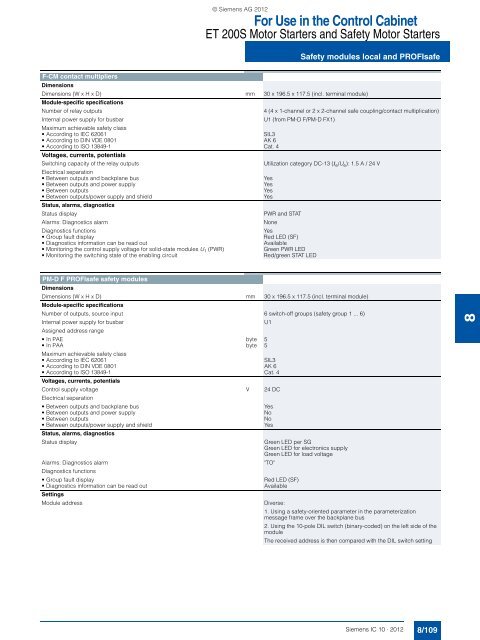
© Siemens AG <strong>2012</strong>For Use in the Control CabinetET 200S Motor Starters and Safety Motor StartersSafety modules local and PROFIsafeF-CM contact multipliersDimensionsDimensions (W x H x D) mm 30 x 196.5 x 117.5 (incl. terminal module)Module-specific specificationsNumber of relay outputsInternal power supply for busbarMaximum achievable safety class• According to IEC 62061SIL3• According to DIN VDE 0801 AK 6• According to ISO 13849-1 Cat. 4Voltages, currents, potentialsSwitching capacity of the relay outputsElectrical separation• Between outputs and backplane bus• Between outputs and power supply• Between outputs• Between outputs/power supply and shieldStatus, alarms, diagnosticsStatus displayAlarms: Diagnostics alarmDiagnostics functions• Group fault display• Diagnostics information can be read out• Monitoring the control supply voltage for solid-state modules U 1 (PWR)• Monitoring the switching state of the enabling circuit4 (4 x 1-channel or 2 x 2-channel safe coupling/contact multiplication)U1 (from PM-D F/PM-D FX1)Utilization category DC-13 (I e /U e ): 1.5 A / 24 VYesYesYesYesPWR and STATNoneYesRed LED (SF)AvailableGreen PWR LEDRed/green STAT LEDPM-D F PROFIsafe safety modulesDimensionsDimensions (W x H x D) mm 30 x 196.5 x 117.5 (incl. terminal module)Module-specific specificationsNumber of outputs, source input 6 switch-off groups (safety group 1 ... 6)Internal power supply for busbarAssigned address range•In PAE byte 5•In PAA byte 5Maximum achievable safety class• According to IEC 62061SIL3• According to DIN VDE 0801 AK 6• According to ISO 13849-1 Cat. 4Voltages, currents, potentialsControl supply voltage V 24 DCElectrical separation• Between outputs and backplane bus• Between outputs and power supply• Between outputs• Between outputs/power supply and shieldStatus, alarms, diagnosticsStatus displayAlarms: Diagnostics alarmDiagnostics functions• Group fault display• Diagnostics information can be read outSettingsModule addressU1YesNoNoYesGreen LED per SGGreen LED for electronics supplyGreen LED for load voltage"TO"Red LED (SF)AvailableDiverse:1. Using a safety-oriented parameter in the parameterizationmessage frame over the backplane bus2. Using the <strong>10</strong>-pole DIL switch (binary-coded) on the left side of themoduleThe received address is then compared with the DIL switch setting8Siemens <strong>IC</strong> <strong>10</strong> · <strong>2012</strong>8/<strong>10</strong>9