Datasheet HCA-100M-50K-C High Speed Current Amplifier
Datasheet HCA-100M-50K-C High Speed Current Amplifier
Datasheet HCA-100M-50K-C High Speed Current Amplifier

Create successful ePaper yourself
Turn your PDF publications into a flip-book with our unique Google optimized e-Paper software.
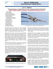
<strong>Datasheet</strong><br />
<strong>HCA</strong>-<strong>100M</strong>-<strong>50K</strong>-C<br />
<strong>High</strong> <strong>Speed</strong> <strong>Current</strong> <strong>Amplifier</strong><br />
Features • Bandwidth DC ... 100 MHz<br />
• Transimpedance (Gain) 5 x 10 4 V/A<br />
• Suitable for <strong>High</strong> Source Capacitance up to 20 pF<br />
• Low Equivalent Input Noise <strong>Current</strong> of 3.8 pA/√Hz<br />
Applications • Photodiode and Photomultiplier <strong>Amplifier</strong><br />
• Spectroscopy<br />
• Charge <strong>Amplifier</strong><br />
• Ionisation Detectors<br />
• Preamplifier for Lock-Ins, A/D Converters, etc.<br />
Specifications Test Conditions Vs = ± 15 V, Ta = 25°C<br />
Gain Transimpedance 5 x 10 4 V/A (@ 50 Ω load)<br />
Gain Accuracy ± 2 %<br />
Frequency Response Lower Cut-Off Frequency DC<br />
Upper Cut-Off Frequency (- 3 dB) 100 MHz (± 10 %, @ Csource 2 to 10 pF )<br />
80 MHz (± 10 %, @ Csource 11 to 20 pF)<br />
Max. Source Capacitance 20 pF (incl. cable, e.g. typical coax cable 1 pF/cm)<br />
Rise / Fall Time (10 % - 90 %) 3.4 ns (@ Csource 2 to 10 pF)<br />
4.0 ns (@ Csource 11 to 20 pF)<br />
Gain Flatness<br />
± 0.3 dB<br />
Input Equ. Input Noise <strong>Current</strong> 3.8 pA/√Hz (@ 10 MHz)<br />
Equ. Input Noise Voltage 0.9 nV/√Hz (@ 10 MHz)<br />
Equ. Integrated Noise 0.6 µA peak-peak<br />
Input Bias <strong>Current</strong><br />
12 µA typ.<br />
Input Bias <strong>Current</strong> Drift 3 nA / °C<br />
Offset <strong>Current</strong> Compensation ± 40 µA adjustable by offset trimpot<br />
Input <strong>Current</strong> Range<br />
± 30 µA (for linear amplification)<br />
Input Offset Voltage<br />
< 1 mV<br />
DC Input Impedance<br />
56 Ω (virtual) // 5 pF<br />
Output Output Voltage Range ± 1.5 V (@ 50 Ω load)<br />
for linear operation and low harmonic distortion<br />
Max. Output Voltage Range ± 1.7 V (@ 50 Ω load)<br />
Output Impedance<br />
50 Ω (terminate with 50 Ω load for best performance)<br />
Bias Output Bias Output Voltage Range ± 12 V, adjustable by bias trimpot<br />
Bias Output Impedance 10 kΩ // 1 µF<br />
SOPHISTICATED TOOLS FOR SIGNAL RECOVERY<br />
DE-<strong>HCA</strong>-<strong>100M</strong>-<strong>50K</strong>-C_3/SP/R3/03May07/ Page 1 of 6
<strong>Datasheet</strong><br />
<strong>HCA</strong>-<strong>100M</strong>-<strong>50K</strong>-C<br />
<strong>High</strong> <strong>Speed</strong> <strong>Current</strong> <strong>Amplifier</strong><br />
Specifications (continued)<br />
Power Supply Supply Voltage ± 15 V<br />
Supply <strong>Current</strong><br />
± 50 mA typ.<br />
(depends on operating conditions, recommended<br />
power supply capability minimum ± 150 mA)<br />
Case Weight 210 g (0.5 lbs)<br />
Material<br />
AlMg4.5Mn, nickel-plated<br />
Temperature Range Storage Temperature -40 ... +100 °C<br />
Operating Temperature 0 ... +60 °C<br />
Absolute Maximum Ratings Input Voltage ± 5 V<br />
Power Supply Voltage ± 22 V<br />
Connectors Input BNC<br />
Output<br />
BNC<br />
Power Supply<br />
LEMO series 1S, 3-pin fixed socket<br />
Pin 1: + 15V<br />
Pin 2: - 15V<br />
Pin 3: GND<br />
PIN 2<br />
-Vs<br />
PIN 1<br />
+Vs<br />
PIN 3<br />
GND<br />
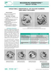
Application Diagrams<br />
Photo Detector Biasing in Photoconductive Mode:<br />
Best choice for high speed applications and<br />
optimum signal to noise performance.<br />
Use additional<br />
Bypass Capacitor<br />
close to Detector<br />
(~100 nF, Ceramic)<br />
CURRENT<br />
INPUT<br />
<strong>HCA</strong><br />
STABILIZED<br />
BIAS VOLTAGE<br />
OUTPUT<br />
<strong>High</strong>-<strong>Speed</strong><br />
<strong>Current</strong> to Voltage<br />
Converter<br />
I/U<br />
Connect the Detector<br />
as close as possible<br />
to the <strong>Amplifier</strong>.<br />
+12 V<br />
BIAS<br />
10 kΩ<br />
470 nF<br />
-12 V<br />
AZ01-0201-20<br />
SOPHISTICATED TOOLS FOR SIGNAL RECOVERY<br />
Page 2
<strong>Datasheet</strong><br />
<strong>HCA</strong>-<strong>100M</strong>-<strong>50K</strong>-C<br />
<strong>High</strong> <strong>Speed</strong> <strong>Current</strong> <strong>Amplifier</strong><br />
Typical Performance<br />
Characteristics<br />
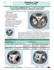
Frequency Response<br />
Noise Spectrum<br />
Note: Spectral noise data is measured at the amplifier output with open but shielded input.<br />
To determine the spectral input noise divide the measured output noise by the amplifier gain<br />
of 5 x 10 4 V/A, i.e.:<br />
Marker Frequency Output Noise Resulting Input Noise<br />
⎯⎯⎯⎯⎯⎯⎯⎯⎯⎯⎯⎯⎯⎯⎯⎯⎯⎯⎯⎯⎯⎯⎯⎯⎯⎯⎯⎯⎯<br />
1 10 MHz 190 nV/√Hz 3.8 pA√Hz<br />
2 100 MHz 273 nV/√Hz 5.5 pA√Hz<br />
SOPHISTICATED TOOLS FOR SIGNAL RECOVERY<br />
Page 3
<strong>Datasheet</strong><br />
<strong>HCA</strong>-<strong>100M</strong>-<strong>50K</strong>-C<br />
<strong>High</strong> <strong>Speed</strong> <strong>Current</strong> <strong>Amplifier</strong><br />
Typical Performance<br />
Characteristics<br />
(continued)<br />
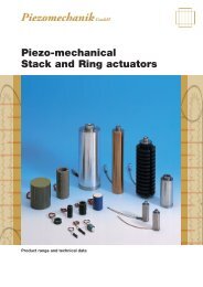
Pulse Response to Square Wave Input Signal<br />
(with 16 times averaging)<br />
Large Signal Response<br />
output signal for 50 MHz, 20 µA peak-peak input signal<br />
(with 4 times averaging)<br />
SOPHISTICATED TOOLS FOR SIGNAL RECOVERY<br />
Page 4
<strong>Datasheet</strong><br />
<strong>HCA</strong>-<strong>100M</strong>-<strong>50K</strong>-C<br />
<strong>High</strong> <strong>Speed</strong> <strong>Current</strong> <strong>Amplifier</strong><br />
Typical Performance<br />
Characteristics<br />
(continued)<br />
Small Signal Response<br />
output signal for 1 MHz, 500 nA peak-peak square wave input signal<br />
(without (top) and with 64 times averaging (bottom))<br />
SOPHISTICATED TOOLS FOR SIGNAL RECOVERY<br />
Page 5
<strong>Datasheet</strong><br />
<strong>HCA</strong>-<strong>100M</strong>-<strong>50K</strong>-C<br />
<strong>High</strong> <strong>Speed</strong> <strong>Current</strong> <strong>Amplifier</strong><br />
Dimensions<br />
94 mm<br />
87 mm<br />
74 mm<br />
IN<br />
<strong>HCA</strong><br />
OUT<br />
12 mm<br />
POWER<br />
14 mm<br />
27 mm<br />
15 mm<br />
44 mm<br />
51 mm<br />
22 mm<br />
∅ 3.3 mm<br />
41 mm<br />
DZ01-0201-22<br />
FEMTO Messtechnik GmbH<br />
Paul-Lincke-Ufer 34<br />
D-10999 Berlin • Germany<br />
Tel.: +49 (0)30 – 4 46 93 86<br />
Fax: +49 (0)30 – 4 46 93 88<br />
e-mail: info@femto.de<br />
http://www.femto.de<br />
Specifications are subject to change without notice. Information furnished herin is believed to<br />
be accurate and reliable. However, no responsibility is assumed by FEMTO Messtechnik<br />
GmbH for its use, nor for any infringement of patents or other rights granted by implication<br />
or otherwise under any patent rights of FEMTO Messtechnik GmbH. Product names<br />
mentioned may also be trademarks used here for identification purposes only.<br />
© by FEMTO Messtechnik GmbH<br />
Printed in Germany<br />
SOPHISTICATED TOOLS FOR SIGNAL RECOVERY<br />
Page 6