Datasheet LIA-MV-200-H Lock-In-Amplifier Module
Datasheet LIA-MV-200-H Lock-In-Amplifier Module
Datasheet LIA-MV-200-H Lock-In-Amplifier Module

Create successful ePaper yourself
Turn your PDF publications into a flip-book with our unique Google optimized e-Paper software.
<strong>Datasheet</strong><strong>LIA</strong>-<strong>MV</strong>-<strong>200</strong>-H<strong>Lock</strong>-<strong>In</strong>-<strong>Amplifier</strong> <strong>Module</strong><strong>In</strong>ternal Connector(of build-in <strong>Lock</strong>-<strong>In</strong> Board)Connector TypeEuro-Card DIN 41612 Connector, 64 pin male, (a+c)<strong>In</strong>put Pin C2: Voltage <strong>In</strong>put, Non <strong>In</strong>verting, DC-CoupledPin C3: Voltage <strong>In</strong>put, Non <strong>In</strong>verting, AC-CoupledPin C4: Voltage <strong>In</strong>put, <strong>In</strong>verting, AC-CoupledPin C5: Voltage <strong>In</strong>put, <strong>In</strong>verting, DC-CoupledPin C7: Current <strong>In</strong>putPin C6: Current <strong>Amplifier</strong> Voltage OutputPin A2- A6: <strong>In</strong>put GNDMonitor Output Pin C9: Monitor OutputPin A9: Monitor GNDOutput Pin C14: X-Signal OutputPin C15: Output GNDOffset <strong>In</strong>put Pin A10: X-Offset <strong>In</strong>putPin A13: Offset GNDStatus Output Pin C10: Unlocked Status OutputPin C11: Overload Status OutputPin C17: Status Output GND (=Power Supply GND)Power Supply Pin A16+C16: Power Supply – 15VPin A18+C18: Power Supply + 15VPin A17+C17: Power Supply GNDRemote Control <strong>In</strong>puts Pin C19: Time Constant (TC0)(Opto-Isolated) Pin A19: Time Constant (TC1)Pin C20: Time Constant (TC2)Pin A20: Time Constant Slope (TCSL)Pin A22: Sensitivity (SEN0)Pin C21: Sensitivity (SEN1)Pin A21: Sensitivity (SEN2)Pin C22: Dynamic Mode (DYN0)Pin A28: Phase Shift (PH0)Pin C28: Phase Shift (PH1)Pin A27: Phase Shift (PH2)Pin C27: Phase Shift (PH3)Pin A26: Phase Shift (PH4)Pin C26: Phase Shift (PH5)Pin A25: Phase Shift (PH6)Pin C25: Phase Shift (PH7)Pin C24: Disable Local Switch ControlPin A23+A24: Remote Control GND(Common Optocoupler Cathode)Reference <strong>In</strong>put Pin A32: Reference <strong>In</strong>putPin A31: Reference <strong>In</strong>put GroundReference Output Pin A30: Reference Output(Connected only if optional Pin A17: Refer. Output GND (=Power Supply GND)Oscillator <strong>Module</strong> is installed) Pin A29: Reference Synchronization <strong>In</strong>putStandard Control <strong>In</strong>terface Pin C29: <strong>In</strong>terface 0(Connected only if optional Pin C30: <strong>In</strong>terface 1Control <strong>In</strong>terface <strong>Module</strong> Pin C31: <strong>In</strong>terface 2(future product) is installed) Pin C32: <strong>In</strong>terface 3SOPHISTICATED TOOLS FOR SIGNAL RECOVERYPage 6
2 PIN-15V<strong>Datasheet</strong><strong>LIA</strong>-<strong>MV</strong>-<strong>200</strong>-H<strong>Lock</strong>-<strong>In</strong>-<strong>Amplifier</strong> <strong>Module</strong>External Connectors(at backside, StandardConfiguration)Signal <strong>In</strong>putX-OutputFactory set to BNC, isolated (single ended)BNCReference <strong>In</strong>putPower SupplyBNCLEMO Series 1S, 3-pin fixed SocketPin 1: + 15VPin 2: - 15VPin 3: GNDPIN 1+15VPIN 3GNDControl Port Sub-D 25-pin, female, Qual. Class 2Pin 1: +12V (Stabilized Power Supply Output)Pin 2: -12V (Stabilized Power Supply Output)Pin 3: AGND (Analog Ground)Pin 4: +5V (Stabilized Power Supply Output)Pin 5: X-OutputPin 6: Overload Status OutputPin 7: Unlocked Status OutputPin 8: Disable Local Switch Control <strong>In</strong>putPin 9: DGND (Ground f. Digital Control Pin 8 - 25)Pin 10: Dynamic Mode (DYN0)Pin 11: Sensitivity (SEN0)Pin 12: Sensitivity (SEN1)Pin 13: Sensitivity (SEN2)Pin 14: Time Constant Slope (TCSL)Pin 15: Time Constant (TC0)Pin 16: Time Constant (TC1)Pin 17: Time Constant (TC2)Pin 18: Phase Shift (PH0)Pin 19: Phase Shift (PH1)Pin 20: Phase Shift (PH2)Pin 21: Phase Shift (PH3)Pin 22: Phase Shift (PH4)Pin 23: Phase Shift (PH5)Pin 24: Phase Shift (PH6)Pin 25: Phase Shift (PH7)Connector Wiring Options General The BNC-connector configuration can be easily changed bysetting electrical jumpers at the internal I/O-adapter card.Disconnect the power supply and open the case byloosening the two upper screws at the case front and rearside. Please pay attention to the ground connection at thebackplane. Now open the case by lifting the top.The jumper options and functions are described in thefollowing table.SOPHISTICATED TOOLS FOR SIGNAL RECOVERYPage 7
<strong>Datasheet</strong><strong>LIA</strong>-<strong>MV</strong>-<strong>200</strong>-H<strong>Lock</strong>-<strong>In</strong>-<strong>Amplifier</strong> <strong>Module</strong>Connector Wiring Options,Jumpers on internalAdapter Board<strong>In</strong>put Connectors (JP1) <strong>In</strong>put wiring Jumper installed⎯⎯⎯⎯⎯⎯⎯⎯⎯⎯⎯⎯⎯⎯⎯⎯⎯⎯⎯⎯⎯IN A = Voltage <strong>In</strong>put "+V-IN → IN A"(Single Ended, AC) "GND → IN A/SHLD""-V-IN → IN A/SHLD"IN A = Voltage <strong>In</strong>put "+V-IN → IN A"(Differential, AC)"-V-IN → IN A/SHLD"IN A / IN B = Voltage <strong>In</strong>put "+V-IN → IN A"(2 BNC Differential, AC) "GND → IN A/SHLD"(OUT A cannot be used) "-V-IN → IN B"IN A = Current <strong>In</strong>put "C-IN → IN A"(Single Ended)"GND → IN A/SHLD""-V-IN → C-OUT"Output Connectors (JP2) Output wiring Jumper installed⎯⎯⎯⎯⎯⎯⎯⎯⎯⎯⎯⎯⎯⎯⎯⎯⎯⎯⎯⎯⎯OUT A = X-Output "X → OUT A"(JP1) "USE OUT A/NO IN B"OUT B = X-Output "X → OUT B"OUT A = Y-Output "Y → OUT A"(JP1) "USE OUT A/NO IN B"OUT B = Y-Output "Y → OUT B"OUT C = Y-Output "Y → OUT C"OUT A = R-Output "R → OUT A"(JP1) "USE OUT A/NO IN B"OUT B = R-Output "R → OUT B"OUT C = R-Output "R → OUT C"OUT B = Monitor Output "MON → OUT B"OUT C = Monitor Output "MON → OUT C"OUT B = Unlocked Output "UNL → OUT B"OUT C = Unlocked Output "UNL → OUT C"OUT B = Overload Output "OVL → OUT B"OUT C = Overload Output "OVL → OUT C"OUT C = Reference Output "REF-OUT → OUT C"Reference Connector (JP3) Reference wiring Jumper installed⎯⎯⎯⎯⎯⎯⎯⎯⎯⎯⎯⎯⎯⎯⎯⎯⎯⎯⎯⎯⎯REF = Reference <strong>In</strong>put "REF-IN → REF" (2 Jumper)(Reference Output only if REF = Reference Output "REF-OUT → REF-IN" (2 Jp.)optional Oscillator <strong>Module</strong> (Reference Output "REF-IN → REF" (2 Jumper)is installed)connected to Ref. <strong>In</strong>put)REF = Refer. Sync. <strong>In</strong>put "REF-SYNC → REF" (2 Jp.)(use OUT C asReference Output)SOPHISTICATED TOOLS FOR SIGNAL RECOVERYPage 8
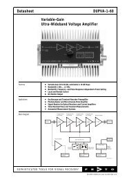
Time-ConstantREFERENCEINPUTSensitivityPhaseCoarseLOCK-IN-AMPLIFIER<strong>LIA</strong>-<strong>MV</strong>-<strong>200</strong>-HPhaseFineDynamicReserveH F 1f 0V2f 2V S L- OUTPUT X(IN-PHASE)ReferenceThresholdSIGNALINPUT<strong>Datasheet</strong><strong>LIA</strong>-<strong>MV</strong>-<strong>200</strong>-H<strong>Lock</strong>-<strong>In</strong>-<strong>Amplifier</strong> <strong>Module</strong>DimensionsTop ViewFront View64,4 mmUnlockedOverloadPowerPLLModeSingle Phase, 50 Hz - 120 kHz105,0 mm223,0 mmBack ViewPOWERPIN 1PIN 2CONTROL-15V+15VPIN 3GNDCase Material:Al, natural anodisedDZ01-1072-10Optional Extensions Reference Oscillator <strong>Module</strong> Model No.: SOM-1- Frequency Range 5 Hz ... 130 kHz, User adjustable- Output Voltage 0 ... 2 Vrms, User adjustable- 100 ppm/K Amplitude AccuracyFactory Set1 kHz, 1 VrmsFEMTO Messtechnik GmbHPaul Lincke-Ufer 34D-10999 Berlin GermanyTel.: +49 (0)30 – 4 46 93 86Fax: +49 (0)30 – 4 46 93 88e-mail: info@femto.dehttp://www.femto.deSpecifications are subject to change without notice. <strong>In</strong>formation furnished herin is believed tobe accurate and reliable. However, no responsibility is assumed by FEMTO MesstechnikGmbH for its use, nor for any infringement of patents or other rights granted by implicationor otherwise under any patent rights of FEMTO Messtechnik GmbH. Product namesmentioned may also be trademarks used here for identification purposes only.© by FEMTO Messtechnik GmbHPrinted in GermanySOPHISTICATED TOOLS FOR SIGNAL RECOVERYPage 10