Tenaga Nasional Berhad
Tenaga Nasional Berhad
Tenaga Nasional Berhad

You also want an ePaper? Increase the reach of your titles
YUMPU automatically turns print PDFs into web optimized ePapers that Google loves.
<br />
Vision<br />
To be among the leading corporations<br />
in energy and related businesses globally<br />
Mission<br />
We are committed to excellence<br />
in our products and services<br />
Shared values<br />
Our shared values provide us with<br />
a principle that will shape our<br />
business ethics and operations<br />
q<br />
q<br />
q<br />
q<br />
Customer first<br />
Business excellence<br />
Integrity<br />
Caring<br />
TENAGA<br />
NASIONAL B E R H A D
Acknowledgement<br />
<strong>Tenaga</strong> <strong>Nasional</strong> <strong>Berhad</strong> would like to acknowledge those that have<br />
actively contributed towards this effort in revisiting the TNB’s Supply<br />
Application Handbook initially launched in 2001.<br />
In our endeavor to provide more effective and efficient service to our<br />
customers, your inputs have been of tremendous help to us to further<br />
improve and add more substance to the initial First Edition.<br />
Special thanks to Federation of Malaysia Consumers Association<br />
(FOMCA), Federation of Malaysian Manufacturers (FMM), Association of<br />
Consulting Engineers of Malaysia (ACEM), The Electrical and Electronics<br />
Association of Malaysia (TEEAM), Real Estate and Housing Developers’<br />
Association (REHDA) and Jabatan Kerja Raya (JKR) for their written<br />
comments and all others that have contributed in more ways than one to<br />
the publication of the 2 nd Edition of the Supply Application Handbook.<br />
<br />
TENAGA<br />
NASIONAL B E R H A D
CONTENTS<br />
SUPPLY APPLICATION<br />
1.0 <strong>Tenaga</strong> <strong>Nasional</strong> <strong>Berhad</strong> Electricity System ........................................................................5<br />
2.0 Supply Application for Load up to 100kVA ......................................................................2<br />
3.0 Supply Application for Load Exceeding 100kVA .............................................................<br />
............................................................. 14<br />
4.0 Application Process for Streetlight ....................................................................................20<br />
CONNECTION GUIDELINES<br />
1.0 Planning for Connection ....................................................................................................22<br />
2.0 Planning and Design Criteria .............................................................................................29<br />
3.0 Demand Estimation ...........................................................................................................42<br />
4.0 Supply Schemes .................................................................................................................44<br />
METERING GUIDELINES<br />
1.0 General ............................................................................................................................51<br />
2.0 Single Phase Metering .......................................................................................................51<br />
3.0 Three Phase Whole Current Metering ...............................................................................54<br />
4.0 Group Metering For Whole Current Metering ..................................................................55<br />
5.0 LVCT Metering ..................................................................................................................56<br />
6.0 Medium and High Voltage Metering .................................................................................58<br />
GLOSSARY AND DEFINITIONS ...........................................................................................63<br />
APPENDIX .................................................................................................................................69<br />
TENAGA<br />
NASIONAL B E R H A D
CONTENTS<br />
1.0 TENAGA NASIONAL BERHAD ELECTRICITY SYSTEM.......................................5<br />
1.1 Introduction ..........................................................................................................................5<br />
1.2 Distribution Division ...........................................................................................................5<br />
1.3 Kedai <strong>Tenaga</strong> .......................................................................................................................6<br />
1.4 Voltages ...............................................................................................................................7<br />
1.5 Supply Frequency ................................................................................................................7<br />
1.6 Earthing System ...................................................................................................................7<br />
1.7 Short Circuit Ratings ...........................................................................................................7<br />
1.8 Act, Regulation and Code ....................................................................................................8<br />
1.9 Supply Voltage Options .......................................................................................................8<br />
1.10 Types of Supply Application ...............................................................................................9<br />
1.11 Consumer Standby Supply ..................................................................................................9<br />
1.12 Alternative Source of Supply ..............................................................................................9<br />
1.13 Provision of Temporary Supply ........................................................................................0 10<br />
1.14 Single Tenant Premise .......................................................................................................0 10<br />
1.15 Multi Tenanted Premises ...................................................................................................0 10<br />
1.16 Turnkey Projects ...............................................................................................................0<br />
...............................................................................................................10<br />
1.17 Connection Charges...........................................................................................................10<br />
1.18 Tariff ..................................................................................................................................<br />
..................................................................................................................................11<br />
1.19 Request for Additional or Special Features .......................................................................<br />
.......................................................................11<br />
1.20 Service Level Agreement (SLA) .......................................................................................11<br />
.......................................................................................<br />
2.0 SUPPLY APPLICATION FOR LOAD UP TO 100kVA ........................................... 12<br />
2.1 Purpose ..............................................................................................................................<br />
..............................................................................................................................12<br />
2.2 What the Applicant Should Do ..........................................................................................12<br />
..........................................................................................<br />
2.3 What the Electrical Contractor Should Do ........................................................................<br />
........................................................................12<br />
2.4 TNB Supply Lead Time ....................................................................................................<br />
....................................................................................................13<br />
2.5 Dispute Between Applicant and Electrical Contractor ......................................................13<br />
......................................................<br />
3.0 SUPPLY APPLICATION FOR LOAD EXCEEDING 100kVA ..............................14<br />
3.1 Purpose ..............................................................................................................................<br />
.............................................................................................................................. 14<br />
3.2 Application Process ...........................................................................................................<br />
........................................................................................................... 14<br />
3.3 Application Parts ...............................................................................................................<br />
............................................................................................................... 14<br />
Part A : Authorities Approval Process .............................................................................<br />
............................................................................. 14<br />
Part B : TNB Technical & Financial Approval Process ...................................................5 15<br />
3.4 What The Applicant Should Do ........................................................................................6 16<br />
3.5 Supply Project Lead Time .................................................................................................7 17<br />
3.6 What The Electrical Consultant Engineer Should Do .......................................................8 18<br />
3.7 Dispute Between Applicant and Electrical Consultant Engineer ......................................9 19<br />
4.0 APPLICATION PROCESS FOR STREETLIGHT ....................................................20<br />
4.1 Purpose ..............................................................................................................................0 20<br />
4.2 Types of Applications ........................................................................................................0 20<br />
4.3 Application by Developer ..................................................................................................0 20<br />
4.4 Application by Individuals/ Local Authority/Government Authority ...............................20<br />
<br />
TENAGA<br />
NASIONAL B E R H A D
1.0 TENAGA NASIONAL BERHAD ELECTRICITY SYSTEM<br />
1.1 Introduction<br />
The <strong>Tenaga</strong> <strong>Nasional</strong> <strong>Berhad</strong> (TNB), a public listed company registered under Companies Act 1965, is charged<br />
with the following responsibilities<br />
• To generate, transmit, distribute and sell energy to consumer throughout Peninsular Malaysia.<br />
• To plan, install, operate and maintain electricity installation for the generation, transmission and distribution<br />
of electricity.<br />
To achieve the above objectives, the company owns and operate power plants and the National Grid, and<br />
installed for this purpose, consumer service centres, call management centres, substations and administrative<br />
offices throughout Peninsular Malaysia. TNB’s core activities are in generation, transmission and distribution<br />
of electricity which are being handled by 3 Divisions :<br />
• Generation Division<br />
• Transmission Division<br />
• Distribution Division<br />
1.2 Distribution Division<br />
Distribution Division supplies electricity in strict accordance with the provisions of the Electricity Supply Act<br />
1990, the Licensee Supply Regulations 1990 and the Electricity Regulations 1994 (and all amendments thereto).<br />
Distribution Division is divided into 2 main regional operational areas where operational efficiency is further<br />
enhanced through the creation of 2 main regional areas, headed by the respective Senior General Managers<br />
which covers :<br />
Area<br />
Region 1<br />
Region 2<br />
States<br />
Selangor, Wilayah Persekutuan, Putrajaya/Cyberjaya,<br />
Negeri Sembilan, Melaka and Johor<br />
Perlis, Kedah, Pulau Pinang, Perak,<br />
Pahang, Terengganu and Kelantan<br />
The States are comprised of main jurisdiction areas under the care of Area Managers. Some areas have smaller<br />
jurisdiction areas and are managed by Branch Managers. All district offices (areas and branches) have one or<br />
more Kedai <strong>Tenaga</strong> under their jurisdiction.<br />
Kedai <strong>Tenaga</strong> provides functions pertaining to Application for Supply, Billing & Collection, Upgrading of<br />
Services and other consumer related activities.<br />
The technical aspects of the operations of the areas include planning, designing, construction, and system<br />
operation and maintenance that delivers supply to the Consumer.<br />
The support departments at the headquarters include Finance, Engineering, Human Resource Management,<br />
Materials Resource Management, Strategic Management and Organisational Development and Consumer<br />
Services and Marketing.<br />
TENAGA<br />
NASIONAL B E R H A D
1.3 Kedai <strong>Tenaga</strong><br />
Kedai <strong>Tenaga</strong> is TNB’s Service and Advisory Centre. It provides TNB’s consumers with Consumer Service<br />
and Elektrik Bestari, TNB’s first branded service that provides electricity advisory service for the home. There<br />
are 145 Kedai <strong>Tenaga</strong> centres throughout Peninsular Malaysia at your service. Please refer to Appendix 1 for<br />
complete information on Kedai <strong>Tenaga</strong> centres throughout Peninsular Malaysia. This list is subject to changes<br />
and may be reviewed from time to time.<br />
Kedai <strong>Tenaga</strong> is where TNB as a caring and friendly utility touches base with its consumers. At Kedai <strong>Tenaga</strong>,<br />
you may experience directly our value-added services which we have specially made available to you, our<br />
valued consumers. Services provided at Kedai <strong>Tenaga</strong> include:<br />
a) One stop payment counter for all electricity and other utility bills.<br />
• Come and meet our friendly personnel who will handle all your utility bills transactions.<br />
Payment can be made by cash, cheque or credit card.<br />
• You can also make arrangements to have your electricity bills paid through banks or<br />
ATM cards.<br />
• TNB, being a caring company, is always concerned about elderly and handicapped consumers<br />
who have genuine problems in settling their bills due to financial difficulties. TNB is aware of<br />
the difficulties encountered and special arrangements can be made for easy payment schemes<br />
for this group of people.<br />
b) Electricity supply application<br />
• At Kedai <strong>Tenaga</strong>, we offer you advice on all matters pertaining to your supply application.<br />
• For wiring purposes in your house, you may choose from a varied selection of contractors<br />
from our directory of registered electrical contractors. This directory enables you to select a<br />
contractor who is base close to your home. It ensures further efficiency and convenience.<br />
• We help you to find out the requirements for supply application in your home.<br />
c) Inquiries pertaining to billing and others.<br />
• Come and visit us to discuss or obtain further clarification on any billing inquiries that you<br />
have. Our front line staff will be happy to help you in resolving any problems you might have<br />
with these inquiries.<br />
d) TNB also offers the following services to its valued consumers:<br />
• Appointments to have the meter read in case the premises are locked during working hours.<br />
• Meter change if consumers suspect that the meter is faulty. If a consumer feels that the meter is<br />
not recording accurately, a written application should be submitted to have the meter tested. A<br />
fee of RM5 will be charged. However, if upon testing the meter it is found that the inaccuracy<br />
is more than 3%, the meter will be replaced and the testing fee of RM5 will be refunded.<br />
• Reconnection of supply to consumers’ premises if the supply is disconnected due to change of<br />
tenancy (if the premises have been vacant for more than 2 months) or nonpayment bill. For<br />
disconnection due to nonpayment of electricity bills, outstanding balances need to be paid<br />
before electricity supply can be reconnected.<br />
• Disconnection of supply if there is a change of tenancy.<br />
<br />
TENAGA<br />
NASIONAL B E R H A D
e) Elektrik Bestari<br />
TNB provides electricity advisory for the home. Our Kedai <strong>Tenaga</strong> has an Elektrik Bestari corner which provides<br />
consumers with basic information on energy efficiency, safety and related topics. For enquiries on electricity<br />
advisory, consumers may enquire at any nearest Kedai <strong>Tenaga</strong>.<br />
1.4 Voltages<br />
The transmission voltage networks are 500kV, 275kV and 132kV, whilst the distribution voltages are 33kV,<br />
11kV and 415/240 Volts. However, in the case of certain parts of Johor & Perak the distribution voltages may<br />
also include 22kV and 6.6kV.<br />
1.5 Supply Frequency<br />
The supply frequency is 50Hz ± 1%.<br />
1.6 Earthing System<br />
High Voltage and Extra High Voltage<br />
• 3 phase configuration<br />
• solidly earthed or impedance earthed<br />
• overhead lines and underground cable are used extensively for high and extra high voltage distribution<br />
Low Voltage 415/240V<br />
• 3 phase 4 wire system<br />
• neutral point solidly earthed mixture of overhead lines, underground cables and aerial insulated cables<br />
• mixture of overhead lines, underground cables and aerial insulated cables<br />
1.7 Short Circuit Ratings<br />
As a guide, the maximum fault levels for the various voltage systems are as follows. All equipment proposed to<br />
be installed and connected to TNB supply must comply with the stated short circuit ratings:<br />
System<br />
Short circuit rating for 3s<br />
i. 500kV 50 kA<br />
ii. 275kV 40 kA<br />
iii. 132kV 31.5 kA<br />
iv. 66kV 20 kA<br />
v. 33kV 25 kA<br />
vi. 22kV 20 kA<br />
vii. 11kV 20 kA<br />
viii. 6.6kV <br />
20 kA<br />
ix. 415/240 V 31.5 kA<br />
TENAGA<br />
NASIONAL B E R H A D
1.8 Act, Regulation and Code<br />
The electricity supply and installation practice in Peninsular Malaysia are governed by the following :-<br />
1 Electricity Supply Act 1990 – Act 447<br />
2 Licensee Supply Regulations 1990<br />
3 Electricity Regulations, 1994<br />
4 Occupational, Safety & Health Act 1994<br />
5 Malaysian Standard MS IEC 60364 Electrical Installation of Buildings<br />
1.9 Supply Voltage Options<br />
Supply may be provided at any of the declared voltages :-<br />
275 kV, 132kV, 33kV, 22 kV*, 11kV, 6.6 kV* and 415/240V. Generally, supplies to domestic premises are<br />
given at single phase 2-wire or three phase 4-wire. However, the actual supply voltage provided depends on the<br />
magnitude of the individual applicant’s load requirements :-<br />
Low Voltage<br />
i. Single-phase, two-wire, 240V, up to 12 kVA maximum demand<br />
ii. Three-phase, four-wire, 415V, up to 45 kVA maximum demand<br />
iii. Three-phase, four-wire, C.T. metered, 415V, up to 1,000 kVA maximum demand<br />
Medium Voltage & High Voltage<br />
i. Three-phase, three-wire and 11kV for load of 1,000 kVA maximum demand and above<br />
ii. Three-phase, three-wire, 22kV or 33kV for load of 5,000 kVA maximum demand and above<br />
iii. Three-phase, three-wire, 66kV, 132kV and 275kV for exceptionally large load of above 25 MVA maximum<br />
demand<br />
It should be noted that voltages other than the above classifications couldn’t be provided by TNB. However,<br />
consumers can make their own transformation arrangements where necessary.<br />
∗ System for certain parts of Johor and Perak only.<br />
<br />
TENAGA<br />
NASIONAL B E R H A D
1.10 Types Of Supply Application<br />
All new applications and upgrade of supply requirement can be classified into three (3) types of supply<br />
applications.<br />
1) Supply Application For Load Up To 100kVA<br />
• Supply usually from existing supply mains<br />
• Submission of applications to TNB by Electrical Contractor registered with the Energy Commission<br />
• Connection of supply may take a maximum of 3 weeks upon approval from the local authorities<br />
2) Supply Application For Load Exceeding 100kVA<br />
• Supply may require establishment of new substation/substations<br />
• Submission of applications to TNB by Consultant Engineer<br />
• Connection of supply may take a minimum of 6 months depending on the extent of electrical infrastructure<br />
required and approval from the local authorities<br />
3) Supply Application For Streetlight<br />
• Application made by the local authority/government department<br />
• Application by developer<br />
• Application by individual<br />
For any supply involving co-generating, a separate licence need to be obtained from the relevant governing<br />
authority.<br />
1.11 Consumers Standby Supply<br />
Standby generator(s) may be used by the applicant at their premises, subject to compliance with the relevant<br />
laws. The generators shall remain a separate system from TNB distribution system and the applicant shall<br />
declare to TNB on the safe installation of the generator(s).<br />
This may be used in place of TNB’s supply source through a suitable, approved changeover facility under<br />
emergency conditions. The Energy Commission and other relevant authorities govern the generators and standby<br />
supply.<br />
1.12 Alternative Source of Supply<br />
A large consumer may require an alternative source of supply. TNB will provide such alternative supply at an<br />
additional cost.<br />
<br />
TENAGA<br />
NASIONAL B E R H A D
1.13 Provision Of Temporary Supply<br />
Temporary supply can be installed for a period of 6 months. Supply is intended for purposes of electric supply for<br />
temporary work site, festivals and celebrations. The applicant shall provide a suitable corridor for installation of<br />
supply mains and site for metering point. The meter will be installed at a meter board provided by the applicant.<br />
The Electrical Contractor shall test the installation.<br />
If the requirement exceeds 6 months, the approval shall be subject to availability of supply<br />
Application for temporary supply shall be separately submitted, stating the load requirements. The applicant<br />
will be charged full cost and according to the appropriate tariff plus an additional 33% surcharge on the total<br />
monthly bill.<br />
1.14 Single Tenant Premises<br />
If the supply is for a single tenant only (the owner, the developer or the landlord) then the entire supply will<br />
be metered at the applicant’s incoming switchboard. The consumption will be charged at the appropriate tariff<br />
rates.<br />
1.15 Multi Tenanted Premises<br />
If the supply is for multi tenanted premises where part of the supply is intended for the owner, developer or<br />
landlord, and the rest for the tenants in the building, the landlord’s supply and each of the tenant’s supplies will<br />
be separately metered and billed by TNB.<br />
The owner, developer, or landlord shall provide, own, maintain and repair at his own expense the electrical<br />
systems in the buildings including adequate and necessary rising and lateral mains. The design, installation and<br />
operating of such electrical systems shall comply with requirements of all the relevant authorities including the<br />
Energy Commission’s and TNB’s.<br />
1.16 Turnkey Projects<br />
In certain cases, the applicant may apply to undertake the planning and installation of the electrical systems<br />
(including overhead lines, switchgears, cables, based on TNB’s specifications and requirements) with the<br />
assistance of Electrical Consultant Engineer(s) and Electrical Contractor(s). Under the ‘turnkey’ concept the<br />
applicant will then hand over the entire electrical system to TNB. A separate discussion on this will have to be<br />
conducted with TNB.<br />
1.17 Connection Charges<br />
Please refer to the Statement of Connection Charges booklet available at the Kedai <strong>Tenaga</strong>. The booklet is<br />
subjected to change as may be published from time to time.<br />
10 TENAGA<br />
NASIONAL B E R H A D
1.18 Tariff<br />
Please refer to the Tariff booklet available at the Kedai <strong>Tenaga</strong>. Tariffs are subjected to change as may be<br />
published from time to time and approved by the Minister of Energy, Water and Telecommunication<br />
1.19 Request For Additional Or Special Features<br />
Any request for additional or special features eg special request for an additional feeder by applicant, the<br />
applicant will have to pay the full cost of the additional request.<br />
1.20 Service Level Agreement (SLA)<br />
Offer is open to all housing developers to enter into a Service Level Agreement (SLA) with TNB when applying<br />
for electricity supply for housing development (as prescribed under the Housing Development (Control and<br />
Licensing) Act 1966). The scope of the SLA includes the time frame process for connection of supply and the<br />
duties and obligation by TNB and housing developers in ensuring the electricity supply is connected to the<br />
housing projects within the stipulated time to avoid delays in handing over houses to the purchaser.<br />
Please refer to the Kedai <strong>Tenaga</strong> for details on the SLA.<br />
11<br />
TENAGA<br />
NASIONAL B E R H A D<br />
11
2.0 SUPPLY APPLICATION FOR LOAD UP TO 100kVA<br />
2.1 Purpose<br />
The application for the supply of electricity with load up to 100kVA which is for a 3 phase low voltage system<br />
is outlined here.<br />
2.2 What The Applicant Should Do<br />
The applicant should take the following steps to apply for supply of electricity up to 100kVA for a 3-phase<br />
low voltage system.<br />
Steps Action Reference<br />
1<br />
Appoint an Electrical Contractor who is registered with The Energy<br />
Commission, who will act on their behalf and submit the application for the<br />
applicant using the Supply Application Form available at Kedai <strong>Tenaga</strong>.<br />
The Electrical Contractor must be<br />
registered with the Energy Commission<br />
2 Settle connection charges billed by TNB through the Electrical Contractor<br />
Statement of Connection Charges<br />
booklet available at any Kedai <strong>Tenaga</strong><br />
3<br />
After completion of TNB’s work (before installation of meter), the<br />
applicant shall:<br />
• Deposit a sum of money equivalent to 2 months bill or as reviewed from<br />
time to time. For deposit of more than RM2,000, the applicant can settle<br />
either in cash or Bankers Guarantee<br />
• Sign electricity supply contract with TNB through the appointed<br />
Electrical Contractor<br />
Tariff booklet available at the nearest<br />
Kedai <strong>Tenaga</strong><br />
2.3 What The Electrical Contractor Should Do<br />
The Electrical Contractor appointed by the applicant should take the following action:<br />
Steps Action Reference<br />
1 Submit application for the applicant using the Supply Application Form<br />
available at Kedai <strong>Tenaga</strong>.<br />
All documents in checklist must be completed, duly endorsed by the<br />
appropriate competent person(s) of the appropriate category and attached<br />
with the application.<br />
Appendix 3<br />
2 After TNB has :<br />
• validated compliance to checklist<br />
• conducted analysis of supply connection<br />
• reviewed connection charges and issue bill to contractor<br />
Statement of Connection<br />
Charges Booklet available<br />
at any Kedai <strong>Tenaga</strong><br />
The applicant shall settle connection charges to TNB.<br />
3 After TNB has implemented work on site, the Electrical Contractor shall:<br />
• Submit G and H form certifying the internal installations<br />
have been tested<br />
• Arrange for applicant to sign supply contract with TNB<br />
• Arrange appointment for meter installation with TNB<br />
Tariff Booklet available at nearest<br />
Kedai <strong>Tenaga</strong><br />
12 TENAGA<br />
NASIONAL B E R H A D
2.4 TNB Supply Lead Time<br />
The flowchart for the application process is as outlined in Appendix 2. TNB supply lead-time will take up to 3<br />
weeks depending on the approval from the local authorities.<br />
2.5 Dispute Between Applicant And The Electrical Contractor<br />
In the event of a dispute between the applicant and the Electrical Contractor and the applicant wishes to terminate<br />
the services of the Electrical Contractor, the applicant shall duly notify the Electrical Contractor concerned in<br />
writing with the copy extended to TNB. TNB shall not be a party to any dispute or litigation arising thereof.<br />
13<br />
TENAGA<br />
NASIONAL B E R H A D<br />
13
3.0 SUPPLY APPLICATION FOR LOAD EXCEEDING 100kVA<br />
3.1 Purpose<br />
To explain the process for supply application with load exceeding 100kVA.<br />
3.2 Application Process<br />
The application process incorporates not only TNB requirements but taking into account the Government<br />
Development Plan Approval Process in Peninsular Malaysia (except Wilayah Persekutuan Kuala Lumpur and<br />
Putrajaya) issued by the Bahagian Perancangan Dasar & Pembangunan Kementerian Perumahan dan Kerajaan<br />
Tempatan: 2002 Edition.<br />
The inclusion of the said Government procedure shall ensure :<br />
• Infrastructure planning and approval process of the TNB complements the National Policy<br />
• TNB as a member Agency of the Government Development Plan Committee has to ensure complete<br />
transparency of its process through timely responses to Development Plan Approval Process<br />
• TNB Supply Application Process ensures complete agreement of Distribution Division’s plans and the<br />
Consultant Engineers submissions especially on the location and size of substations needed for the supply<br />
of electricity to the development area, and is valid for 2 years after the approval from the Jabatan Perancang<br />
Bandar & Desa (JPBD).<br />
3.3 Application Parts<br />
There are two parts to the application :<br />
Part Function Reference<br />
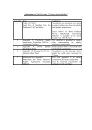
A Requirement of Approval from the Government’s Development Plan Approval Process Appendix 4 & 5<br />
B TNB Application Requirement after completion of Part A Appendix 7<br />
PART A : Authorities Approval Process<br />
The part A process approval that involves TNB’s technical comments is as shown in Development Plan Approval<br />
Process in Appendix 4 & 5. At each application process, TNB requires a processing time of up to 10 days to<br />
complete the comments for Jabatan Perancang Bandar & Desa (JPBD). The main process can be summarised<br />
as follows :<br />
Stage<br />
Description<br />
1 Submit Development Plan<br />
The Consultant Engineer submits development plan application for the proposed development to JPBD.<br />
All plans must be prepared by a licensed surveyor.<br />
The comments from all relevant technical agencies including TNB are required prior to approval by JPBD.<br />
14 TENAGA<br />
NASIONAL B E R H A D
Stage<br />
Description<br />
2 TNB Register Application<br />
The Consultant Engineer/JPBD submits application to TNB complete with required details as in Checklist<br />
in Appendix 6. TNB will:<br />
• Acknowledge receipt and gives a file number, which is used as reference in any dealings with TNB.<br />
Study the proposal. Match the existing system network and determine method of supply.<br />
3 Mutual Understanding Of Plan<br />
Both TNB and Consultant Engineer will conduct discussion to agree to technical requirement such as<br />
substation number, size, location, site and consumers main switch room.<br />
In case of a dispute on TNB proposal, the Consultant Engineer shall refer to the relevant State General<br />
Managers. A discussion shall be arranged by the relevant State General Managers to arrive at an agreement.<br />
4 TNB Submit Comments to JPBD<br />
TNB submit to JPBD the proposed development plans including all technical comments using TNB official<br />
stamp as required by JPBD.<br />
JPB approves the proposed development plan. The validity is subjected to:<br />
- confirmation of layout details and precomputation plans<br />
- no changes in development<br />
- 2 years extension<br />
5 TNB Application for Electricity Supply above 100KVA process starts<br />
(Part B)<br />
PART B : TNB Technical & Financial Approval Process<br />
Part B process is the TNB Application Process for Electricity Supply above 100 KVA as outlined in Appendix<br />
7. The process starts after the completion of Part A (Authorities Approval Process). The Process in Part B can<br />
be summarised as follows:<br />
Stage<br />
1 Submit Application<br />
Description<br />
The Electrical Consultant Engineer submits application for the Electricity Supply to the nearest Kedai<br />
<strong>Tenaga</strong>. Complete details as in Appendix 6 must be submitted with the application.<br />
TNB will issue an acknowledgement letter to the Electrical Consultant Engineer as in Appendix 8 using the<br />
same file reference given during Part A (Authorities Approval Process).<br />
2 Documentation Check And System Study<br />
TNB will advise on the necessary amendment 15 to the consultant by telephone or letter. The Electrical<br />
Consultant Engineer is to ensure that all the amendments are done and resubmitted to TNB.<br />
TENAGA<br />
NASIONAL B E R H A D<br />
15
Stage<br />
3 Joint Meeting<br />
Description<br />
TNB will restudy the amendments and arrange for a joint meeting with the Electrical Consultant Engineer<br />
for final acceptance of the technical requirements. Activities of both parties will be recorded in the Joint<br />
Meeting Action Log as in Appendix 9.<br />
4 Connection Charges<br />
TNB will issue a Notice of Connection Charges to the Electrical Consultant Engineer as per Appendix 10.<br />
5 Electricity Infrastructure Agreement (Optional)<br />
The applicant may decide to enter into an Electricity Infrastructure Agreement with TNB with regard to<br />
TNB scope of work, charges and timely connection.<br />
6 Discussion And Preparation Of Site Work<br />
After payment of connection charges, the Electrical Consultant Engineer will arrange for pre start work<br />
discussion and site and substation building hand over.<br />
7 Construction Completion And Substation Energising<br />
TNB will manage the construction work and is responsible for the commissioning of substations. The<br />
energising of supply by TNB will normally be done at the same time as the installation of the meters. For<br />
HV supply, the supply shall be energised in the presence of the Electrical Consultant Engineer and for LV<br />
consumers in the presence of the Electrical Contractor.<br />
8 Supply Application By The Electrical Contractor<br />
The Consultant Engineer advises the Electrical Contractor to submit supply application for load requirement<br />
up to 100kVA, normally for individual applicant. The process is the same as outlined in Section 2.<br />
3.4 What The Applicant Should Do<br />
The applicant should take the following action in applying for supply application for load exceeding<br />
100KVA.<br />
Steps Action Reference<br />
1 • Appoint one () Electrical Consultant Engineer for each supply application<br />
Appendix 11<br />
• Submit an appointment letter of the Electrical Consultant Engineer allowing him<br />
to act on behalf of the applicant to TNB.<br />
16 TENAGA<br />
NASIONAL B E R H A D
Steps Action Reference<br />
2 After approval from JPBD and TNB completion of work plan, the applicant settles<br />
connection charges to TNB at any Kedai <strong>Tenaga</strong>.<br />
The applicant may decide to enter into an Electricity Infrastructure Agreement with<br />
TNB with regard to TNB scope of work, charges and timely connection.<br />
Statement of<br />
Connection Charges<br />
Booklet available at<br />
Kedai <strong>Tenaga</strong><br />
3 • Provide the substation(s) land and building(s) to TNB by:<br />
- Leasing the substation land at a nominal value of RM10.00 to TNB, or<br />
- Transfer the substation land at a nominal value of RM10.00 to TNB<br />
• The Certificate of Fitness of the substation building/compartment shall be<br />
handed to the TNB.<br />
Statement of<br />
Connection charges<br />
booklet available at<br />
Kedai <strong>Tenaga</strong><br />
The transfer of the land title should be finalised prior to the handing over of site.<br />
In the absence of the land title, the applicant is to prepare a Bank Guarantee for<br />
TNB for the period of twelve () months and shall be renewed until the land title is<br />
transferred to TNB or registration of lease to TNB<br />
Delay in title transfer may affect project implementation. TNB have the right to use<br />
the substation to supply electricity to other consumers.<br />
4 Applicants are required to:<br />
• Deposit a sum of money equivalent to 2 months bill or as reviewed from time to<br />
time. For deposit of more than RM 2,000, the applicant can settle either in cash<br />
or Bankers Guarantee.<br />
• Sign electricity supply contract with TNB through the appointed Electrical<br />
Contractor.<br />
3.5 Supply Project Lead Time<br />
The lead-time for supply connection depends on a number of factors including the type of premises, the electrical<br />
load required and the location of the premises and approval of the local authorities.<br />
Applicants should submit their applications for supply as early as possible giving the necessary information of<br />
their requirements to the nearest Kedai <strong>Tenaga</strong>. They must also inform TNB of the progress of their project(s).<br />
The above measures are necessary to ensure that TNB’s supply projects are coordinated with the construction<br />
and wiring installation at the applicants’ premises, and thus avoid any delay in connection of supply. The typical<br />
supply project lead time required by TNB is as follows:<br />
17<br />
TENAGA<br />
NASIONAL B E R H A D<br />
17
Requirement<br />
Supply Project Typical Lead Time<br />
132 kV and above 3 years – 5 years<br />
33 kV 18 months - 2 years<br />
11 kV 6 months – 12 months<br />
415 V and below Less than 6 months<br />
3.6 What The Electrical Consultant Engineer Should Do<br />
The Electrical Consultant Engineer plays a major role to represent the applicant and ensure compliance with<br />
other relevant government departments and TNB. The Electrical Consultant Engineer is advised to observe the<br />
steps as outlined below:<br />
Steps<br />
1<br />
Action<br />
• Submits application for the proposed development to JPB and TNB<br />
• All plans must be prepared by a Licensed Surveyor<br />
Liaise with TNB to come up with a mutual understanding of plan and to get approval by JPBD<br />
Submits application for the electricity supply to Kedai <strong>Tenaga</strong>.<br />
Complete details as outlined in Appendix 6 and 12 must be submitted with the application. The application must be<br />
accompanied by 3 copies of the following :-<br />
2<br />
i) Location plan<br />
ii) Site plan showing the lot number(s)<br />
iii) The plan of the proposed substation (when relevant)<br />
iv) The proposed electrical wiring system designs<br />
v) The proposed consumer’s switchroom (where applicable)<br />
vi) The approval of the building plans by the relevant Authorities<br />
• Clearly state details of the applicants supply requirements.<br />
Provide a comprehensive description of the proposed development and a list including all detail of the connected<br />
loads, motors/appliances, the associated ratings, type of motor starter and their arrangements (where applicable).<br />
• Submit the metering requirements for CT Meters as in Appendix 20.<br />
3 Ensure that all the amendments are complied with and resubmitted to TNB.<br />
4<br />
5<br />
• Ensure that the applicants main switchroom shall be located adjoining the TNB’s substation or as mutually agreed<br />
to be most appropriate under the specific design<br />
• Provide appropriate cable trenching from the TNB’s substation to the main switchroom and a panel/cubicle for<br />
metering or a free standing meter cubicle in the case of high voltage installation in the consumer’s switchroom or<br />
substation<br />
• Ensure that consumer switchgears, control gears, transformers, relay panels, switchboards, metering current<br />
transformer, potential transformer etc. to be connected to TNB’s system must be approved by the Energy<br />
Commission.<br />
• Appoint an Electrical Contractor for wiring up the premises<br />
• Provide installation test results and protection settings for all CT metered applicants.<br />
6 Ensure that the wiring and the installation work of applicant’s equipment shall be supervised by competent person(s).<br />
18 TENAGA<br />
NASIONAL B E R H A D
Steps<br />
7<br />
8<br />
Action<br />
Advise applicant to submit application form through registered Electrical Contractor. The process is the same as outlined<br />
in Section 2.<br />
Advise applicant to deposit a sum of money equivalent to 2 months bill or as reviewed from time to time. For deposit of<br />
more than RM2,000 the applicant can settle either in cash or Bankers Guarantee.<br />
3.7 Dispute Between Applicant And Electrical Consultant Engineer<br />
In the event of a dispute between the applicant and the Electrical Consultant Engineer and the applicant wishes<br />
to terminate the services of the Electrical Consultant Engineer, the applicant shall duly notify the Electrical<br />
Consultant Engineer concerned in writing with the copy extended to TNB. TNB shall not be a party to any<br />
dispute or litigation arising thereof.<br />
19<br />
TENAGA<br />
NASIONAL B E R H A D<br />
19
4.0 Application Process for Streetlight<br />
4.1 Purpose<br />
This procedure outlines the process for the application for streetlight.<br />
4.2 Types of Applications<br />
The three () types of application for streetlights are:<br />
• Application made by the local authority/government authority<br />
• Application by developer<br />
• Application by individual<br />
4.3 Application by Developer<br />
The local authority or developer should take the following steps to apply for streetlight.<br />
Steps<br />
Action<br />
1 Appoint a Consultant Engineer and an Electrical Contractor that is registered with the Energy<br />
Commission.<br />
2 The application is made together with the supply application for a new housing development with<br />
all the load details of the proposed public lighting that is approved by the local authority.<br />
4.4 Application By Individuals/Local Authority/Government Authority<br />
The application process is similar for both individuals and local authority or government authority. Individuals<br />
must already have an account with TNB. The installation of streetlight depends on:<br />
• Installation of streetlight on existing TNB pole<br />
• Installation involving additional poles<br />
IF<br />
Installation of streetlight on existing<br />
TNB pole<br />
Installation involving<br />
additional poles<br />
THEN<br />
Consumer submits application to the Kedai <strong>Tenaga</strong>.<br />
The applicant settles the full cost of additional new pole/poles<br />
installed.<br />
20 TENAGA<br />
NASIONAL B E R H A D
CONTENTS<br />
Page<br />
<br />
1.0 PLANNING FOR CONNECTION ......................................................................................... 22<br />
1.1 Declaration Of Loads And Its Characteristics ............................................................................ 22<br />
1.1.1 Supplies at 415V and 240V .............................................................................. 22<br />
1.1.1.1 Technical Requirements For Connection ............................................ 23<br />
1.1.2 Supplies at 275kV, 132kV, 33kV, 22kV, 11kV and 6.6kV ............................... 23<br />
1.1.3 Supplies To Embedded / Distributed Generators ............................................. 24<br />
1.1.3.1 Planning Data Requirements For Connection of Embedded /<br />
Distributed Generators......................................................................... 24<br />
1.1.3.2 Pre-connection Studies For Embedded / Distributed Generators ....... 27<br />
1.2 Other Information Requirements .................................................................................. 28<br />
2.0 PLANNING AND DESIGN CRITERIA ............................................................................... 29<br />
2.1 Steady-State Supply Voltage Performance .................................................................... 29<br />
2.2 Supply Security Level ................................................................................................... 29<br />
2.2.1 Adopted Security Level Definitions For TNB Distribution System ................ 30<br />
2.2.2 Supply Security Level to Consumers ............................................................... 30<br />
2.2.3 Request For Higher Supply Security Level ..................................................... 30<br />
2.3 Power Quality ............................................................................................................... 30<br />
2.3.1 Power Quality Requirements ........................................................................... 30<br />
2.3.2 Scope ................................................................................................................ 31<br />
2.3.3 Voltage Dips/Sags ............................................................................................ 31<br />
2.3.4 Voltage Step Change ........................................................................................ 32<br />
2.3.5 Voltage Fluctuations and Flicker ..................................................................... 33<br />
2.3.6 Harmonics ........................................................................................................ 35<br />
2.3.7 Voltage Unbalance ........................................................................................... 38<br />
2.4 Short-Circuit Levels ...................................................................................................... 39<br />
2.5 Protection Requirements ............................................................................................... 40<br />
2.5.1 Basic Requirements .......................................................................................... 40<br />
2.5.2 Specific Requirement ........................................................................................ 40<br />
2.5.3 Protection System Evaluation Process ............................................................. 41<br />
3.0 DEMAND ESTIMATION ........................................................................................... 42<br />
3.1 Demand Estimates For Consumer Sub-Classes Or Premises ........................................ 42<br />
3.2 Group Diversity ............................................................................................................. 43<br />
3.3 Demand Estimates For A Mixed Development Area .................................................... 43<br />
3.4 Demand Projection And Substation Requirements For LV Scheme ............................. 43<br />
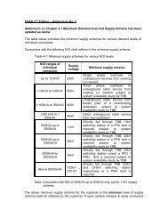
4.0 SUPPLY SCHEMES.................................................................................................................. 44<br />
4.1 Maximum Demand Levels And Supply Schemes ......................................................... 44<br />
4.2 Substation Categories, Type & Design .......................................................................... 44<br />
4.2.1 Sub-Station Categories ..................................................................................... 44<br />
4.2.2 Land Or Building Size Requirements For Sub-Station .................................... 46<br />
4.2.3 Type Of Fire Fighting System For The Sub-Station ......................................... 47<br />
4.3 Standard And Special Feature Design Schemes ............................................................ 47<br />
4.4 Supply Schemes For Interconnection To Embedded Generators .................................. 47<br />
TENAGA<br />
NASIONAL B E R H A D<br />
21
SECTION 1: PLANNING FOR CONNECTION<br />
Sets of data and information are to be furnished by Electrical Contractors and Electrical Consultant Engineers acting on<br />
behalf of consumers or developers at the time of application of supply and prior to connection of supply.<br />
Based upon submitted data and information, TNB will plan for the connection system to satisfy the planning and design<br />
criteria and use the best engineering practices to ensure reasonable cost of equipment, materials and workmanship as<br />
well as reasonable time period for connection of supplies.<br />
1.1 DECLARATION OF LOADS AND ITS CHARACTERISTICS<br />
TNB requires adequate information on magnitude and characteristics of the loads to be consumed by consumer or<br />
installation.<br />
1.1.1 Supplies at 415V and 240V<br />
For supplies at Low Voltages of 240V and 415V, the Consumer shall, in the appropriate application forms for<br />
connection obtainable from TNB provide the following data.<br />
(a) Maximum power requirements in kVA;<br />
(b) Types and number of equipment and its corresponding connected capacity in kVA;<br />
(c) Shunt connected reactors and capacitors in kVAr;<br />
(d) The date when connection is required;<br />
(e) For single-phase 240V motors with rating of greater than 6kVA and/or three-phase 415V motors<br />
with rating greater than 75kVA, the following information shall be provided for each motor;<br />
(i) Rating in HP or KVA;<br />
(ii) Types of control equipment;<br />
(iii) Methods of starting and starting current;<br />
(iv) Frequency of starting (number/hour); and<br />
(v) Rated power factor;<br />
(f) Voltage sensitive loads (indicating sensitivity)<br />
Where a preliminary examination of the above data indicates that more detailed information is required, the<br />
consumer shall provide additional information upon request by TNB.<br />
22 TENAGA<br />
NASIONAL B E R H A D
1.1.1.1 Technical Requirements For Connection<br />
For connections at Low Voltage the consumer’s installation shall comply with the Electricity Supply Act 1990<br />
and any regulations made there under and Malaysian Wiring Regulations and any requirements specified by<br />
TNB based on Malaysian MS-IEC Standards.<br />
In the case of connections to Consumers at Low Voltage, TNB has the responsibility to specify any technical<br />
requirements for the connection. This includes specification of technical requirements associated with loads<br />
which may give rise to voltage fluctuations and harmonics.<br />
1.1.2 Supplies at 275kV, 132kV, 33kV, 22 kV, 11kV and 6.6kV<br />
For supplies at voltages of 275kV, 132kV, 33kV, 22kV, 11kV and 6.6kV, the Consumer shall provide comprehensive<br />
information on the loads and their characteristics including but not limited to the following:<br />
a)<br />
For all types of loads:<br />
(i) Maximum Active Power consumption in kW; and<br />
(ii) Maximum Reactive Power consumption in kVAR.<br />
b)<br />
For motor loads:<br />
(i) Types of control equipment;<br />
(ii) Methods of starting;<br />
(iii) Magnitude and duration of the starting current;<br />
(iv) Frequency of starting (number/hour);<br />
(v) Under voltage setting and time;<br />
(vi) Negative phase sequence protection; and<br />
(vii) Sub-transient and/or locked rotor reactance of the motor.<br />
c)<br />
For nonlinear loads with harmonic current injections:<br />
(i) Harmonic current spectrum including harmonic number and the corresponding maximum<br />
current.<br />
d) For fluctuating loads:<br />
(i) The rates of change of Active Power and Reactive Power consumption in kW/minute and<br />
kVAR/minute respectively, both increasing and decreasing;<br />
(ii) The shortest repetitive time interval between fluctuations for Active Power and Reactive Power<br />
in minutes; and<br />
(iii) The magnitude of the largest step changes in Active Power and Reactive Power in kW and<br />
kVAR respectively, both increasing and decreasing.<br />
TENAGA<br />
NASIONAL B E R H A D<br />
23
e)<br />
f)<br />
For voltage sensitive loads:<br />
(i) steady-state voltage tolerance limits of the equipment in percentage of the nominal voltage;<br />
(ii) intrinsic immunity limits to short duration voltage variation;<br />
(iii) transient voltage tolerance limits of the equipment in percentage of the nominal voltage and the<br />
corresponding duration;<br />
(iv) harmonic current emission limit for equipment.<br />
For Shunt Connected Reactors and Capacitors:<br />
(i) configuration and sizes of individual banks;<br />
(ii) types of switching and control equipment; and<br />
(iii) types of harmonic filtering reactors.<br />
Should a preliminary examination of the above data indicate that a more detailed information is required, the<br />
consumer shall provide the information upon request by TNB.<br />
TNB upon receipt of the data and information should perform assessments of the impacts of the loads on<br />
TNB’s distribution system. Consumers shall then be advised on TNB’s design of supply scheme and other<br />
technical requirements to be complied with by the consumers to ensure system performance is within the limits<br />
or standard.<br />
1.1.3 Supplies To Embedded / Distributed Generators<br />
1.1.3.1 Planning Data Requirements For Connection Of Embedded / Distributed Generators<br />
Embedded / distributed generator installations are treated as a different consumer class. For the purposes of planning<br />
the connection of a Distributed Generator to the Distribution System, TNB requires sufficient information to model the<br />
generating plant and carry out engineering studies for determining the method of connection to be employed, the voltage<br />
level of connection and its impacts on the Distribution System. The Distributed Generator shall provide the following<br />
information to TNB for planning purposes.<br />
(a) For all Generating Units<br />
(i) Terminal voltage;<br />
(ii) Rated kVA;<br />
(iii) Rated kW;<br />
(iv) Maximum Reactive Power sent out or minimum lagging power factor;<br />
(v) Maximum Reactive Power absorbed or minimum leading power factor;<br />
(vi) Type of Generating Unit – synchronous, asynchronous, etc.<br />
(vii) Type of prime mover;<br />
(viii) Type of voltage control;<br />
(ix) Generating Unit sub-transient reactance;<br />
(x) Generating Unit transformer details;<br />
(xi)<br />
Requirements for Top-Up Supply and/or Standby Supply.<br />
24 TENAGA<br />
NASIONAL B E R H A D
Should a preliminary examination of the above data indicate that more detailed information is required; the Distributed<br />
Generator shall provide additional information as follows upon request by TNB.<br />
(b) For a Generating Unit with a capacity greater than 3 MW, the following additional information shall be<br />
provided to TNB by the Distributed Generator:<br />
(i) Generating Unit electric and mechanical data (all impedance (unsaturated) in p.u. of rating and time<br />
constants in seconds)<br />
• Type of prime mover<br />
• Rated MVA<br />
• Rated MW<br />
• Generating Unit rotor and turbine moment of inertia or inertia constant<br />
• Generating Unit MW / MVAR capability chart\<br />
• Type of excitation system<br />
• Stator resistance<br />
• Direct-axis sub-transient reactance<br />
• Direct-axis transient reactance<br />
• Direct-axis synchronous reactance<br />
• Quadrature-axis sub-transient reactance<br />
• Quadrature-axis transient reactance<br />
• Quadrature-axis synchronous reactance<br />
• Direct-axis sub- transient open circuit time constant<br />
• Direct-axis transient open circuit time constant<br />
• Quadrature-axis sub-transient open circuit time constant<br />
• Quadrature-axis transient open circuit time constant<br />
• Zero sequence resistance<br />
• Zero sequence reactance<br />
• Negative sequence resistance<br />
• Negative sequence reactance<br />
• Generating Unit open circuit saturation curve<br />
(ii) Generating Unit transformer data<br />
• MVA rating<br />
• % resistance<br />
• % reactance<br />
• Tap range in p.u.<br />
• Tap step in p.u.<br />
• Vector group<br />
• Method of earthing<br />
TENAGA<br />
NASIONAL B E R H A D<br />
25
(iii) Automatic voltage regulator (AVR) data<br />
• A block diagram for model of the AVR including the data in gains, forward and feedback gains,<br />
time constant and voltage control limits and limit characteristics.<br />
(iv) Speed governor and prime mover data<br />
A block diagram for the model of the generating unit speed governor including its control parameters,<br />
time constants, gains, valve limits, temperature controls, deadbands, turbine rating, maximum and<br />
minimum power, penstock parameters, tunnel parameter, surge chamber parameters and all other<br />
relevant data.<br />
Should a preliminary examination of the above data indicate that more detailed information is required;<br />
the Distributed Generator shall provide additional information upon request by TNB.<br />
(c)<br />
For Fixed Speed Asynchronous Induction Generating Units the following data may be required:<br />
• Stator Current at unity power factor<br />
• Stator Current max at lagging power factor<br />
• Stator Current min at lagging power factor<br />
• Magnetizing reactance<br />
• Stator resistance<br />
• Stator reactance<br />
• Inner cage or running rotor resistance<br />
• Inner cage or running rotor reactance<br />
• Outer cage or standstill rotor resistance<br />
• Outer cage or standstill rotor reactance<br />
• For the above state whether derived from inner outer cage or running-standstill measurements<br />
• Slip at rated output per unit<br />
• Load torque-speed coefficient B<br />
• Load torque-speed coefficient C<br />
• Inertia constant for generator prime mover drive chain<br />
Note:<br />
The torque-speed (T-N) relationship is defined as:<br />
T = T 0<br />
(A + BN = CN 2 ) where A = 1.0 – B – C<br />
Therefore only B & C are needed.<br />
Alternatively a per unit torque-speed curve can be provided.<br />
• Describe method of adding star capacitance over the operating range<br />
26 TENAGA<br />
NASIONAL B E R H A D
• Capacitance connected in parallel at % of rated output Starting<br />
20%<br />
40%<br />
60%<br />
80%<br />
100%<br />
• Maximum starting current in Amps<br />
• Starting Regime - Symmetrical RMS current at time t from energisation:<br />
- t = 0 ms<br />
- t = 50 ms<br />
- t = 200 ms<br />
- t = 1 s<br />
- t = 5 s<br />
• The operating chart to show range of reactive import and export with compensation as a function<br />
of Active Power.<br />
• Details of the turbine and governor model, described in block diagram form showing transfer<br />
functions of individual elements<br />
The Distributed Generator will need to provide the above characteristic for each asynchronous<br />
Generating Unit based on the number of pole sets (i.e. Two data sets are required for dual speed 4/6<br />
pole machines).<br />
For large sites, with multiple machines, the Distributed Generator may alternatively provide an equivalent network<br />
modelled as an asynchronous Generating Unit with matching Generating Unit Transformer at the Connection Point. This<br />
equivalent should also model the site electrical network and power factor correction, etc.<br />
Should a preliminary examination of the above data indicate that more detailed information is required; the Distributed<br />
Generator shall provide additional information upon request by TNB.<br />
1.1.3.2 Pre-Connection Studies For Embedded / Distributed Generators<br />
The following pre-connection studies are necessary for the purpose of designing the interconnection facilities for<br />
embedded / distributed generators:-<br />
(i) System studies of embedded / distributed generator installation encompassing load flow, short-circuit,<br />
stability, load rejection or islanding studies and protection coordination studies. The part of preconnection<br />
studies is to be carried by a consultant appointed the owner of embedded / distributed<br />
generator. The associated costs shall be borne by the owner of embedded generator. The results of study<br />
will be presented to TNB for evaluation.<br />
TENAGA<br />
NASIONAL B E R H A D<br />
27
(ii)<br />
TNB upon receiving the above study and other necessary data shall conduct an integrated study of the<br />
interconnected systems. The scope of study will include load flow, short-circuit, stability and protection<br />
coordination studies. The costs of this study will also be borne by the owner of generator seeking<br />
interconnection with the distribution system.<br />
1.2 OTHER INFORMATION REQUIREMENTS<br />
Other sets of information as listed below are necessary for TNBD to plan for connection of supply to consumers.<br />
1. Site plan or location plan (see Appendix ) indicating the geographical position of the premises/buildings<br />
of consumers. This information is essential for TNB to locate TNB’s infrastructure nearest to the prospective<br />
consumers.<br />
2. Layout plan (see Appendix ) for developed/proposed development. This information is necessary for TNB to<br />
locate sub-station locations, if not previously identified, and feeder routes for MV or LV networks. Sketched layout<br />
plans are required for individual or group applications less than 100KVA. Additional information, which needs to<br />
be specified in the supply application form, is the position of prospective consumer with respect to LV system or<br />
sub-station in terms of distance and estimated number of spans of LV feeders.<br />
3. Building layout plans are particularly useful for indicating services entrance location/positions, position of substations<br />
and consumer switch rooms.<br />
4. Sub-station layout plan for both sub-stations integrated into a building or in separate building.<br />
5. Consumer switch room layout indicating location of main switchboard, service cable entry position and necessary<br />
ducting or trenching.<br />
6. Wiring diagrams of installation to be approved and endorsed by Electrical Consultant Engineer for demand greater<br />
than 100kVA. The single line drawing of the installation must encompass the complete installations indicating<br />
incoming switches, main and sub-switchboards, main protection for incoming TNB supply as well as sub-circuit<br />
protection, metering schemes, conductor sizes, major equipment e.g motors etc., standby generators, capacitor<br />
banks. Ratings of switchgears and components must also be indicated.<br />
7. Appendix 14 is the form which registers the consent or acknowledgement of developer/owner for leasing/transfer<br />
of sub-station lot to TNB. This form is to be submitted by Electrical Consulting Engineers, acting on behalf of<br />
consumers, for projects requiring substations.<br />
Appendix 6 is a checklist for reference to consumers, electrical contractors and consultant engineers on range data<br />
or information required at the supply application processing stage.<br />
28 TENAGA<br />
NASIONAL B E R H A D
SECTION 2.0 PLANNING AND DESIGN CRITERIA<br />
TNB in developing the connection system or supply infrastructure needs to satisfy a set of planning and design criteria<br />
which are described in this section.<br />
2.1 STEADY-STATE SUPPLY VOLTAGE PERFORMANCE<br />
(a)<br />
Steady-State Voltage Fluctuation under Normal Condition<br />
Under normal condition, when all circuit elements are in service, the distribution network including<br />
the points before the consumer metering must be planned to be maintained as is table 2-1 below:-<br />
Table 2-1: Steady -state voltage level fluctuation limits under normal conditions<br />
Voltage level<br />
% variation<br />
415V and 240V -10% & +5%<br />
6.6kV, 11kV, 22kV,33kV +/- 5%<br />
132kV and 275kV -5% & +10%<br />
(b)<br />
Steady-State Voltage Fluctuation under Contingency Condition<br />
Under contingency condition, when one or more circuit elements are on outage, the power frequency<br />
steady-state voltage at all points in the distributor’s distribution system including the points before the<br />
consumer metering must be planned to be maintained as follows:<br />
Table 2-2: Steady-State Voltage Fluctuation Limits under Contingency Condition<br />
Voltage level<br />
% variation<br />
415V and 240V +/- 10%<br />
6.6kV, 11kV, 22kV,33kV +10 & -10%<br />
132kV & 275kV +/- 10%<br />
2.2 SUPPLY SECURITY LEVEL<br />
Supply security of a distribution system network defines the availability of supply to consumers following the occurrence<br />
of supply interruption. Systems and necessary network management infrastructure may be designed to meet any of the<br />
standardized security level definitions currently adopted by TNB as indicated in table 2-3.<br />
TENAGA<br />
NASIONAL B E R H A D<br />
29
2.2.1 Adopted Security Level Definitions For TNB Distribution Systems<br />
Table 2-3: Security Levels for Distribution Network<br />
Security Level<br />
Level 1<br />
Level 2<br />
Level 3<br />
Level 4<br />
Average Restoration Period<br />
Less than 5 seconds<br />
Less than 15 minutes<br />
Less than 4 hours<br />
Less than 24 hours<br />
2.2.2 Supply Security Level to Consumers<br />
For supplies to consumers at voltage levels of 6.6kV, 11kV, 22kV and 33kV, large part of the network are generally<br />
designed to facilitate an average supply restoration of less than 4 hours. For supplies at 240V and 415V, the restoration<br />
period may vary beyond 4 hours depending on the type of network fault.<br />
2.2.3 Request for Higher Supply Security Level<br />
However, TNB can design the supply scheme to meet higher security level requirement of individual consumer or group<br />
of consumers. All additional costs involved in providing the higher security level shall be borne by the consumer.<br />
2.3 POWER QUALITY<br />
2.3.1 Power Quality Requirements<br />
2.3.1.1 The electromagnetic disturbance covers the following phenomena:<br />
a. Voltage fluctuations and flickers<br />
b. Harmonics up to order of 50 th<br />
c. Voltage dips and short supply interruptions<br />
d. Voltage unbalance<br />
e. Inter-harmonics up to 50 th<br />
f. Voltage distortions at higher frequencies (above 50 th harmonics)<br />
g. Transient overvoltages<br />
h. Power frequency variation<br />
i. Dc components<br />
j. Mains signaling<br />
30 TENAGA<br />
NASIONAL B E R H A D
For the purpose of this guideline, Power Quality is defined as the degree to which the voltage at the point<br />
of connection to the consumer of the Distribution Network is maintained to be Sinusoidal at Rated Voltage<br />
Magnitude and Frequency. In this guideline only items a to d are considered.<br />
2.3.1.2 This section specifies the Power Quality requirements of the electricity supply to be delivered to the consumers<br />
in the TNB distribution system in terms of voltage and frequency to be within specific limits so that the consumer<br />
s’ equipment directly connected to the TNB distribution system can operate safely within its design performance<br />
without suffering undue damage or breakdown. Likewise this guidelines shall be complied with by all consumers<br />
connected and who intend to be connected to the TNB distribution system.<br />
2.3.1.3 In order to achieve the required Power Quality, these guidelines will be used by TNB in planning, developing,<br />
maintaining and operating the distribution system and in connecting Distributed Generation and Demand to the<br />
distribution system.<br />
2.3.1.4 In cases where, the nature and operation of the new types of plant and equipment to be connected to the<br />
distribution system is perceived to be likely to cause problems to customers connected to the System, but not<br />
fully covered by this guidelines, expert advice will be sought to ensure the appropriate remedial measures are<br />
put in place.<br />
2.3.2 Scope<br />
2.3.2.1 This guidelines covers most of the power quality related phenomena generated by various types of plant and<br />
equipment connected to the distribution system as well as those generated by the transmission system. In each<br />
particular case the Distribution Power Quality that should be maintained is indicated together with the remedial<br />
approach and responsibilities of parties.<br />
2.3.3 Voltage Dips/Sags<br />
2.3.3.1 This guidelines does not specifically cover the requirements for transient phenomena which can affect the<br />
voltage level known as voltage “dip” or “sag” and “swell” usually experienced during system faults and the<br />
subsequent recovery period, which can adversely affect some customer equipment sensitive to such changes.<br />
Currently, there is no local or international guidelines that has been established to specify requirements of the<br />
supply voltage to the consumers with respect to the magnitude and duration of voltage dips and swells.<br />
TENAGA<br />
NASIONAL B E R H A D<br />
31
2.3.3.2 Guidelines and guides that exist with respect to voltage dips and swell are those that describe the environment in<br />
which the sensitive voltage equipment may experience which include typical number of voltage sag experiences<br />
and their duration. The main purpose of such guidelines is to ensure that equipment designed to be connected to<br />
the distribution systems to be compatible with the supply voltage performance in terms of various power quality<br />
problems including voltage sags.<br />
2.3.3. Malaysian Standard MS 1760:2004 760:00 “Guides on Voltage Dips and Short Interruptions on Public Electric Power<br />
Supply Systems” contains definitions and descriptions of voltage sags and short interruptions. MS1760:2004 is<br />
based on IEC 61000-2-8 with some limited data on the characteristics for Malaysia. The purpose of the Guides<br />
is to discuss voltage dips and short interruptions primarily as phenomena observed on public supply systems and<br />
its effects on voltage sensitive equipment receiving supply from such systems.<br />
2.3.3.4 There exist standards on immunity of equipment to supply voltage fluctuations and distortion with defined<br />
magnitude and duration of voltage dips and harmonics. IEC 61000-2 series of guidelines set out the supply<br />
characteristics e.g. IEC 61000-2.8 as indicated above. IEC 61000-3 series of guidelines sets out the compatibility<br />
levels which should be achieved when designing electrical equipment which may give rise to voltage fluctuations<br />
and harmonic distortion and when connecting such equipment to the distribution system, which will give<br />
immunity to interference to similar equipment connected to the distribution system. MS IEC 61000-4-11 & MS<br />
IEC 61000-4-34 series of standards specifies test methods.<br />
2.3.3.5 Some equipment suppliers and trade organisations also specify the immunity levels for certain types of equipment<br />
for example Semiconductor Industry Guidelines SEMI F47, Computer and Business Equipment Manufacturing<br />
Association CBEMA Compatibility Guidelines.<br />
2.3.3.6 TNB shall upon request from any customer advise the consumer having connected voltage sensitive loads<br />
or intending to connect voltage sensitive loads in their installation to take into account the short duration<br />
electromagnetic disturbance phenomena for selecting equipment with proper maximum intrinsic immunity.<br />
2.3.4 Voltage Step Change<br />
2.3.4.1 Limits of voltage changes due to Load, frequent and infrequent operational switching of Load both by TNB and<br />
the consumer are defined table 2.3.4.1. These limits are based on UK’s Engineering Recommendation P2 P2 on<br />
“Planning Limits for Voltage Fluctuations Caused by Industrial, Commercial and Domestic Equipment in the<br />
United Kingdom”, 1989.<br />
32 TENAGA<br />
NASIONAL B E R H A D
Table 2.3.4.1: Voltage limits on switching of load<br />
Load Starting/Switching<br />
Limit of Voltage<br />
Change<br />
Starting/switching once or twice a year 6%<br />
Infrequent single starting/switching or<br />
disconnection of Load – once in two hours<br />
or more hours. Including capacitor or<br />
reactor bank<br />
Frequent starting/switching and/or<br />
disconnection of Load (e.g., Many times<br />
in a day)<br />
3%<br />
1%<br />
2.3.5 Voltage Fluctuations and Flicker<br />
2.3.5.1 The limits of Flicker that are acceptable on the distribution system are in accordance with the “Engineering<br />
Recommendation P28, Issued by The Electricity Council of UK in 1989 entitled Planning Limits for Voltage<br />
Fluctuation Caused by Industrial, Commercial and Domestic Equipment in the United Kingdom”. TNB uses the<br />
procedures contained in this document to plan the connection of Fluctuating Loads and applies the limits therein<br />
in measuring and monitoring the levels of Flicker at such points of connection.<br />
2.3.5.2.2 In accordance with the “Engineering Engineering Recommendation P2”, P2”, voltage fluctuations at a Point of Common<br />
Coupling with a fluctuating Load directly connected to the Distribution System shall not exceed:<br />
(a) % of the voltage level for step changes, which may occur repetitively. Any large voltage excursions other<br />
than step changes or less frequent step changes may be allowed up to a level of 3% provided that this<br />
does not constitute a risk to the distribution system or, in TNB’s view, any other party connected to the<br />
distribution system.<br />
(b) The planning limits for the Short and Long Term Flicker Severity applicable for Fluctuating Loads connected<br />
to the distribution system are as set out in the table below.<br />
TENAGA<br />
NASIONAL B E R H A D<br />
33
Table 2.3.5.2 : Maximum allowable flicker severity<br />
TNB distribution system<br />
Voltage Level at which the<br />
Fluctuating Load is<br />
Connected<br />
Absolute Short<br />
Term Flicker<br />
Severity (P st<br />
)<br />
Absolute Long<br />
Term Flicker<br />
Severity (P lt<br />
)<br />
500, 275 and 132kV 1.0 0.8<br />
Less than 132kV 0.8 0.6<br />
2.3.5.3 In connecting a Fluctuating Load at a particular point or Point of Common Coupling it is necessary to assess the<br />
total Flicker due to the Fluctuating Load itself and the background Flicker measured at that point. In assessing<br />
the total Flicker TNB shall use the so called “RSS Rule”. This assessment is carried out by the RSS Rule by<br />
obtaining the sum of the squares of the Flicker from the Fluctuating Load and the background Flicker, with the<br />
square root of this sum yielding the total assessed Flicker at that Point of Common Coupling due to the specific<br />
Fluctuating Load and the background Flicker at that point.<br />
2.3.5.4 Connection of more than one Fluctuating Load at the same Point of Common Coupling or addition of further<br />
Fluctuating Load at the same location is carried out on a “first come first served” basis on the distribution system.<br />
This means that whilst the first Fluctuating Load may be within the allowable Flicker limits and not require<br />
any Flicker mitigation or compensation equipment, the second Fluctuating Load which may cause violation<br />
of Flicker limits will be obliged to invest in appropriate Flicker mitigation or compensation equipment. At<br />
the planning stage, in carrying out the assessment of the total Flicker due to more than one Fluctuating Load<br />
connecting at a particular Points of Common Coupling, TNB shall use the methodology described in P28.<br />
2.3.5.5 In assessing the level of Flicker due to a Fluctuating Load at the planning stage the assessment will be carried<br />
out at a realistic System operating condition giving the minimum number of connections with which that point<br />
on the System can be operated within normal voltage limits and following Secured Contingency Events. This<br />
condition shall be considered as representative of the type of System conditions under which the Flicker due to<br />
a Fluctuating Load will be at its highest value as the voltage fluctuations due to the Fluctuating Load will be at<br />
their highest level under such conditions.<br />
34 TENAGA<br />
NASIONAL B E R H A D
2.3.5.6 If under the operating conditions described in 2.3.5.5 the Flicker due to a Fluctuating Load exceeds the limits<br />
then Flicker compensation, which will reduce the Flicker to an acceptable level shall be installed. For the<br />
avoidance of doubt the acceptance Criteria for Flicker is the 95% values of Short and Long Term Flicker<br />
Severity i.e., P st<br />
and P lt<br />
will be below the limits specified in table 2.3.5.2. Here the 95% values mean the values<br />
of Flicker Severity measured and observed during 95% of the total observation period. The System overall<br />
performance yardstick for the level of Flicker reduction to be achieved shall be based upon enabling connection<br />
of other similar Fluctuating Load and/or permitting for future extension and development of the location with<br />
further Fluctuating Load installations. The Flicker compensation method and equipment to be used shall be<br />
of a type that does not cause resonance problems with the existing and intended future developments of the<br />
distribution system.<br />
2.3.5.7 If the permissible Flicker limits cannot be met even with installation of Flicker compensation at a particular<br />
Points of Common Coupling at a particular System voltage level then connection of the Fluctuating Load at a<br />
higher voltage level or elsewhere in the System shall be considered. The connection point of choice will need<br />
to have to experience lower voltage fluctuations than the first connection point considered under the operational<br />
conditions in 2.3.5.5.<br />
2.3.6 Harmonics<br />
2.3.6.1 All plant and equipment connected to the Distribution System, and that part of the TNB distribution system at<br />
each connection site, should be capable of withstanding the following distortions of the voltage waveform in<br />
respect of harmonic content. The maximum total levels of Harmonic Distortion at any connection point on the<br />
distribution system from all sources under both planned outage and Secured Contingency Event conditions,<br />
unless abnormal conditions prevail, shall not exceed:<br />
(a) at 33kV and 22kV, a Total Harmonic Distortion of 3% with no individual harmonic voltage greater than that<br />
shown in the tables X;<br />
(b) at 11kV and 6.6kV, a Total Harmonic Distortion of 4% with no individual harmonic voltage greater than that<br />
shown in the tables Y;<br />
(c) at 415V and below, a Total Harmonic Distortion of 5% with no individual harmonic voltage greater than that<br />
shown in the tables Z;<br />
(d) infrequent short duration peaks may be permitted by TNB to exceed the above levels for harmonic<br />
distortion;<br />
TENAGA<br />
NASIONAL B E R H A D<br />
35
2.3.6. .2 A Consumer who intends to connect non-linear loads to the TNB system shall carry out assessment harmonic<br />
distortion levels for the connection of each non-linear Load to the Distribution System. TNB will verify the<br />
results of the assessments.<br />
2.3.6. Consumers shall ensure that the Immunity Level of their plant and Apparatus is compatible with the<br />
electromagnetic disturbances present on the System including harmonics.<br />
2.3.6. .4 In assessing the level of harmonic distortion and individual harmonic levels at the planning stage, the assessment<br />
will be carried out at a realistic system operating condition giving the minimum number of connections with<br />
which that point on the system can be operated within normal voltage limits and following secured contingency<br />
events. This condition shall be considered as representative of the type of system conditions under which the<br />
harmonic distortion and individual harmonic levels will be at their highest level.<br />
2.3.6.5.5 If under the operating conditions describes in ..6. 2.3.6.1 (a) (a) the harmonic distortion and individual harmonic levels<br />
due to the load exceed the limits then harmonic filters which will reduce the harmonics to an acceptable level<br />
shall be installed to bring the levels within limits. The system overall performance yardstick for the level of<br />
harmonic reduction to be achieved shall be based upon enabling connection of other similar harmonic producing<br />
load and/or permitting for future extension and development of the location with further harmonic producing<br />
load installations.<br />
2.3.6.6.6 The planning limits of harmonics that are acceptable of the distribution system are in accordance with MS<br />
IEC 61000-3-6 “ Assessment of emission limits for distorting loads in MV & HV power systems”, and where<br />
appropriate Engineering Recommendations G5/4 is adopted.<br />
2.3.6.7.7 TNB uses the procedures contained in this document to plan the connection of loads producing harmonics and<br />
applies the limits therein in measuring and monitoring the levels of harmonics at such points of connection.<br />
These are given in summary in the tables below.<br />
36 TENAGA<br />
NASIONAL B E R H A D
Table X: Planning Levels for Harmonic Voltages in TNB distribution systems >20kV to 145kV (22kV and<br />
33kV) including background harmonics<br />
Odd Harmonics<br />
(Non-multiple of 3)<br />
Order<br />
“h”<br />
5<br />
7<br />
11<br />
13<br />
17<br />
19<br />
23<br />
25<br />
>25<br />
Harmonic<br />
Voltage (%)<br />
5.0 (2.0)<br />
4.0 (2.0)<br />
3.0 (1.5)<br />
2.5 (1.5)<br />
1.6 (1.0)<br />
1.2 (1.0)<br />
1.2 (0.7)<br />
1.2 (0.7)<br />
0.2+0.5(25/h)<br />
Order<br />
“h”<br />
Odd Harmonics<br />
(Multiple of 3)<br />
Harmonic<br />
Voltage (%)<br />
Order<br />
“h”<br />
Values in brackets are the Engineering Recommendation G5/4 levels.<br />
3<br />
9<br />
15<br />
21<br />
>21<br />
4.0 (2.0)<br />
1.2 (1.0)<br />
0.3<br />
0.2<br />
0.2<br />
2<br />
4<br />
6<br />
8<br />
10<br />
12<br />
>12<br />
The total harmonic distortion level is 6.5 % (3%)<br />
Even Harmonics<br />
Harmonic<br />
Voltage (%)<br />
1.6 (1.0)<br />
1.0 (0.8)<br />
0.5<br />
0.4<br />
0.4<br />
0.2<br />
0.2<br />
Table Y: Planning Levels for Harmonic Voltages in TNB distribution systems 6.6kV and 11kV including<br />
background harmonics<br />
Odd Harmonics<br />
(Non-multiple of 3)<br />
Odd Harmonics<br />
(Multiple of 3)<br />
Even Harmonics<br />
Order<br />
Harmonic<br />
Order<br />
Harmonic<br />
Order<br />
Harmonic<br />
“h”<br />
Voltage (%)<br />
“h”<br />
Voltage (%)<br />
“h”<br />
Voltage (%)<br />
5<br />
7<br />
11<br />
13<br />
17<br />
19<br />
23<br />
25<br />
>25<br />
5.0 (3.0)<br />
4.0 (3.0)<br />
3.0 (2.0)<br />
2.5 (2.0)<br />
1.6<br />
1.2<br />
1.2<br />
1.2 (0.7)<br />
0.2+0.5(25/h)<br />
3<br />
9<br />
15<br />
21<br />
>21<br />
4.0 (3.0)<br />
1.2<br />
0.3<br />
0.2<br />
0.2<br />
2<br />
4<br />
6<br />
8<br />
10<br />
12<br />
>12<br />
The total voltage harmonic distortion level is 6.5 % (4%)<br />
1.6 (1.5)<br />
1.0<br />
0.5<br />
0.4<br />
0.4<br />
0.2<br />
0.2<br />
Values in brackets are the Engineering Recommendation G5/4 levels.<br />
TENAGA<br />
NASIONAL B E R H A D<br />
37
Table Z: Planning Levels for Harmonic Voltages in TNB distribution systems 415V and below including<br />
background harmonics<br />
Odd Harmonics<br />
Odd Harmonics<br />
(Non-multiple of 3)<br />
(Multiple of 3)<br />
Even Harmonics<br />
Order Harmonic Order Harmonic Order Harmonic<br />
“h” Voltage (%) “h” Voltage (%) “h” Voltage (%)<br />
5<br />
4.0<br />
7<br />
4.0<br />
2 1.6<br />
11<br />
3.0<br />
3<br />
4.0 4 1.0<br />
13<br />
2.5<br />
9<br />
1.2 6 0.5<br />
17<br />
1.6<br />
15<br />
0.3 8 0.4<br />
19<br />
1.2<br />
21<br />
0.2 10 0.4<br />
23<br />
1.2 >21 0.2 12 0.2<br />
25<br />
0.7<br />
>12 0.2<br />
>25 0.2+0.5(25/h)<br />
The total voltage harmonic distortion level is 5%<br />
Note: The above table shows the Engineering Recommendation G5/4 levels. TNB is in the process of adopting<br />
IEC levels and the values in the above table will be updated later<br />
2.3.7 Voltage Unbalance<br />
2.3.7.1 All plant and equipment connected to the distribution system, and that part of the distribution system at each<br />
connection site, should be capable of withstanding the following distortions of the voltage waveform in respect<br />
of Voltage Unbalance at the planning stage.<br />
) Under planned outage conditions, the maximum negative phase sequence component of the phase voltage<br />
on the distribution system should remain below 1% unless abnormal conditions prevail.<br />
) Under the planned outage conditions, infrequent short duration peaks with a maximum value of 2% are<br />
permitted for Voltage Unbalance, subject to the prior agreement of TNB under the connection agreement.<br />
TNB will only agree following a specific assessment of the impact of these levels on TNB and other<br />
Customers’ plant and equipment with which it is satisfied.<br />
38 TENAGA<br />
NASIONAL B E R H A D
3) At the terminals of a Customer’s installation or specific Load the Voltage Unbalance voltage shall not<br />
exceed 1% for 5 occasions within any 30 minute time period.<br />
) In terms of traction Loads connected to the distribution system the acceptable limits of Voltage Unbalance<br />
are in accordance with “Engineering Recommendation (E/R) P29, issued by the Electricity Council of UK<br />
in 1984 entitled “AC Traction Supplies to British Rail” and its successor document P 29 issued in 1990<br />
“Planning Limits for Voltage Unbalance in the United Kingdom”. TNB uses the procedures contained in<br />
this document to plan the connection of Loads producing Voltage Unbalance and applies the limits therein<br />
in measuring and monitoring the levels of unbalance at such points of connection.<br />
2.3.7.2 In assessing level of Voltage Unbalance at the planning stage the assessment will be carried out at a realistic<br />
System operating condition giving the minimum number of connections with which that point on the System<br />
can be operated within normal voltage limits with maintenance outages and following Secured Contingency<br />
Events. This condition shall be considered as representative of the type of System conditions under which the<br />
Voltage Unbalance will be at its highest value.<br />
2.3.7.3 If under the operating conditions described earlier the Voltage Unbalance due to the Load exceeds the limits then<br />
balancing compensation equipment, which will reduce the unbalance to an acceptable level shall be installed<br />
to bring the levels within the limits. The System overall performance yardstick for the level of unbalance<br />
reduction to be achieved shall be based upon enabling connection of other similar unbalance producing Load<br />
and/or permitting for future extension and development of the location with further unbalance producing Load<br />
installations. The balancing compensation equipment to be installed shall be of a type that does not cause<br />
resonance problems with the existing and intended future developments of the distribution system.<br />
2.4 SHORT-CIRCUIT LEVELS<br />
TNB network are design and operated in order to remain within the limits of short-circuit levels as in Table 2-4. TNB<br />
equipment design are specified to the same S.C rating. Consumer equipment at the point of interface or part of the<br />
interconnection design shall also the minimum S.C rating. TNB may provide indicative or prospective fault level in<br />
terms of X/R ratio at the interface point with consumer, if so required for detailed installation design. Values in table 2-4<br />
gives the maximum short-circuit level at the various voltage levels.<br />
TENAGA<br />
NASIONAL B E R H A D<br />
39
Table 2-4: Short-circuit levels for various voltage levels<br />
Supply Voltage Level S.C Rating<br />
275kV 40 kA for 3s<br />
132kV 31.5 kA for 3s<br />
33kV 25 kA for 3s<br />
22kV & 11kV 20 kA for 3s<br />
6.6 kV 20 kA for 3s<br />
415V & 240V 31.5 kA for 3s<br />
2.5 PROTECTION REQUIREMENTS<br />
2.5.1 Basic Requirements<br />
In all cases, the basic requirement is that the consumer’s arrangements for protection at the connection point, including<br />
types of equipment and protection settings, must be compatible with standard practices on the TNB’s system, and be as<br />
TNB specifies during the application for supply process. This is especially critical for MV and HV consumers.<br />
2.5.2 Specific Requirements<br />
Consumers shall take into consideration the following specific protection practices of TNB in designing their<br />
installation:<br />
(a)<br />
(b)<br />
(c)<br />
Maximum clearance times (from fault current inception to fault clearing) must be within the limits established<br />
TNB in their short circuit rating policy for the distribution system.<br />
Auto-reclosing or sequential switching features may be used on TNB’s distribution system. TNB will provide<br />
details on the operating sequence utilised for the supplies on the proposed installation so the consumer can plan<br />
for this in the design and protection of his facility.<br />
On some of TNB’s distribution systems, certain types of faults may cause disconnection of one phase only of a<br />
three-phase supply.<br />
40 TENAGA<br />
NASIONAL B E R H A D
2.5.3 Protection System Evaluation Process<br />
Consumer’s installation to supplied at 11kV and above shall provide the appropriate and matching protection scheme<br />
to support the desired operation of the designed supply scheme. The reliability of the equipment, protective devices and<br />
protection systems being deployed at the consumer connection or interface points may effect the reliability of TNB’s<br />
supply system.<br />
Submission of schematic of<br />
installation indicating proposed<br />
protection schemes for incoming<br />
points<br />
Review of installations protection<br />
scheme and design of supply scheme<br />
to consumer<br />
Consumer advised on required changes<br />
to match planned supply schemes<br />
Submission of device<br />
specifications & test results<br />
Submission of Protection<br />
Coordination Studies of internal<br />
installation & proposed setting<br />
TNB performed integrated<br />
protection coordination studies &<br />
confirm setting<br />
Witness testing and verification at<br />
site before commissioning<br />
Fig 2-1 Protection System Evaluation Process<br />
Figure 2-1 above illustrates the steps involved in the evaluation of protection schemes.<br />
TENAGA<br />
NASIONAL B E R H A D<br />
41
SECTION 3.0: DEMAND ESTIMATION<br />
Supply schemes and networks are to be adequately designed or dimensioned to meet initial and growth of consumer<br />
individual and group maximum demand.<br />
The demand estimates are based upon load declared by consumer and TNB’s own information on load profile<br />
characteristics for various consumer classes. Range of values are given as demand profile are known to varies according<br />
to geographical location of consumers around the TNB service areas in Peninsular Malaysia.<br />
Fairly accurate assessment of individual and group demand of consumers are critical for correct dimensioning of network<br />
or facilities in meeting the initial and future demand of consumers as imposed on the network.<br />
3.1 Demand Estimates For Consumer Sub-Classes Or Premises<br />
Table 3-1 and 3-2 indicates the typical ranges of maximum demand for domestic and shop-lots or shop-houses respectively.<br />
These values shall be subjected to revisions based upon of latest results load profiling studies.<br />
Table 3-1: Range of maximum demand (M.D) for domestic consumer sub-classes or premises<br />
No:<br />
1<br />
2<br />
3<br />
4<br />
5<br />
Type Of Premises<br />
Low cost flats, single storey<br />
terrace<br />
Double storey terrace or<br />
apartment<br />
Single storey, semidetached<br />
Single storey bungalow &<br />
three-room condominium<br />
Double storey bungalow &<br />
luxury condominium<br />
Minimum<br />
(kW)<br />
Average<br />
(kW)<br />
Maximum<br />
(kW)<br />
1.5 2.0 3.0<br />
3.0 4.0 5.0<br />
3.0 5.0 7.0<br />
5 7.0 10<br />
8.0 12 15<br />
Table 3-2: Range of maximum demand (M.D) for types of shop-houses<br />
No:<br />
Type Of Premises<br />
Minimum<br />
(kW)<br />
Average<br />
(kW)<br />
Maximum<br />
(kW)<br />
1 Single storey shop house 5 10 15<br />
3 Double storey shop house 15 20 25<br />
3 Three storey shop house 20 30 35<br />
4 Four storey shop house 25 35 45<br />
5 Five storey shop house 30 40 55<br />
42 TENAGA<br />
NASIONAL B E R H A D
3.2 Group Diversity<br />
Group diversity is applied in the computation of unit demand and group demand. The typical values for diversity factors<br />
for various consumer classes is as in the table below.<br />
Table 3-3: Typical Group Diversity Values<br />
Consumer classes<br />
Domestic<br />
Less than 10 consumers<br />
More than 10 consumers<br />
Commercial or industrial<br />
Less than 10 consumers<br />
More than 10 consumers<br />
Group Diversity factors<br />
0.80<br />
0.75<br />
0.80<br />
0.75<br />
3.3 Demand Estimates For A Mixed Development Area.<br />
Accurate determination of the maximum possible demand for a newly proposed development is critical in the effective<br />
long-term planning of supply network within the specific area. Adequate land areas for transmission main intakes (PMU<br />
132/33kV, 132/22kV, 132/11kV), major distribution stations (PPU 33/11kV, 22/11kV), sub-stations (PE 11/. 415kV,<br />
22/. 415kV), underground cable and overhead line routes will have to be allocated at the layout approval stage by the<br />
relevant authorities.<br />
The total demand will indicate the supply voltage and target network configuration for the whole development area.<br />
Network facilities will be developed in phases in tandem with physical development.<br />
Site selections for PMU, PPU, sub-stations and feeder routes are normally made to achieve optimal technical performance<br />
of network and costs based on the planned target network.<br />
Appendix 15 indicates the sample M.D worksheet for a mix development area to be filled up and submitted to TNB at<br />
the supply application stage.<br />
3.4 Demand Projection And Substation Requirements For LV Scheme<br />
Demand projection of a new development area, say a proposed housing scheme, determines the number of sub-station<br />
requirements (11/. 415kV) in the design of low voltage system.<br />
Appendix 16 indicates the method for determining the overall numbers and capacity of sub-station for a typical housing<br />
or commercial scheme based upon the projected demand growth.<br />
TENAGA<br />
NASIONAL B E R H A D<br />
43
SECTION 4: SUPPLY SCHEMES<br />
Based upon consumer declared demand level and required security level, supply schemes to consumers are appropriately<br />
designed to meet these requirements and planning criteria as discussed in section 2.<br />
4.1 Maximum Demand Levels And Supply Schemes<br />
The table below indicates the typical schemes for various demand levels of individual consumers. In the case of<br />
maximum demand (M.D) ranges of 5MVA to 10MVA, the supply voltage options of either 11kV or 33kV will ultimately<br />
be determined by the predominant supply voltage where the prospective consumer is to be connected.<br />
Consumers with M.D approaching 1000kVA have the option of taking supply at 11kV.<br />
Table 4-1: Typical supply schemes for various M.D levels<br />
M.D ranges of individual<br />
consumer<br />
Supply<br />
voltage<br />
Typical supply scheme<br />
Up to 12 KVA 240V Overhead services from LV mains.<br />
12kVA to 100kVA<br />
100kVA to 1000kVA<br />
1000kVA to 5000kVA<br />
1000kVA to 10000kVA<br />
5000kVA to 25000kVA<br />
Above 25000kVA<br />
415V<br />
415V<br />
11kV<br />
22kV<br />
33kV<br />
132kV ,<br />
275 kV<br />
Three phase overhead or underground<br />
cable service from existing LV mains.<br />
Direct cable service from LV board from<br />
a sub-station<br />
Directly fed through TNB 11kV switching<br />
station<br />
Directly fed through TNB 22kV switching<br />
station<br />
Directly fed through TNB 33kV switching<br />
station<br />
Directly fed through TNB 132kV and<br />
275kV switching station respectively<br />
4.2 Substation Categories, Type & Design<br />
4.2.1 Sub-station categories<br />
a. Transmission Main Intake (Pencawang Masuk Utama-PMU)<br />
Transmission Main Intake is the interconnection point of 132kV or 275kV to the distribution network. The standard<br />
transmission capacity and voltage transformation provided at the PMU are as follows:-<br />
44 TENAGA<br />
NASIONAL B E R H A D
- 132/33kV, 2 x 90 MVA<br />
- 132/22kV, 2 x 60 MVA<br />
- 132/11kV, 2 x 30 MVA<br />
b. Main Distribution Sub-station (Pencawang Pembahagian Utama- PPU)<br />
Main Distribution Sub-station is normally applicable to 33kV for interconnecting 33kV networks with 11kV networks.<br />
It provides capacity injection into 11kV network through a standardized transformation of 33/11kV.<br />
c. Main Switching Station (Stesyen Suis Utama- SSU)<br />
SSU at 33kV, 22kV and 11kV are established to serve the following function:-<br />
1. To supply a dedicated bulk consumer ( 33kV, 22kV, 11kV)<br />
2. To provide bulk capacity injection or transfer from a PMU/PPU to a load center for further localized distribution.<br />
d. Distribution Substation (Pencawang Elektrik – P/E)<br />
Distribution sub-stations are capacity injection points from 11kV, 22kV and sometimes 33kV systems to the low voltage<br />
network (415V, 240V). Typical capacity ratings are 1000kVA, 750kVA, 500kVA and 300kVA.<br />
Conventional substation designs are of indoor type (equipment housed in a permanent building) and out-door type<br />
(ground-mounted or pole-mounted). Standardized M & E design of 11/. 433kV sub-station is available at TNB offices.<br />
Compact substation (11/. 415kV) has limited application and is to be strictly applied in selective situations under the<br />
following circumstances:-<br />
• System reinforcement projects for highly built-up areas where substation land is difficult to acquire.<br />
• Any request to use compact substation for dedicated supply to a single or limited group of low voltage consumers is<br />
subject to TNB approval in accordance to site constraints situation, and to be considered as ‘special feature design<br />
schemes’.<br />
The main reasons for the above application criteria are as follows:-<br />
• Compact design reduces future system flexibility in terms of network expansion.<br />
• Compact design features, which limits the capacity of outgoing circuits.<br />
TENAGA<br />
NASIONAL B E R H A D<br />
45
4.2.2 Land Or Building Size Requirements For Sub-Stations<br />
Table 4-2 : Land and building size requirements for sub-stations<br />
Note: Set-back<br />
Substation<br />
Category<br />
Transmission Main Intake/<br />
Pencawang Masuk Utama<br />
(PMU):<br />
(a) 132/33/11kV<br />
Transmission Main Intake/<br />
Pencawang Masuk Utama<br />
(PMU):<br />
(a) 132/33/11kV<br />
Main Distribution Substation<br />
(PPU)<br />
(a) /11kV<br />
(b) /11kV<br />
Main Distribution Substation<br />
(PPU)<br />
(a) /11kV<br />
(b) 22/11kV<br />
Main Switching Substation<br />
(SSU)<br />
(a) kV<br />
(b) kV<br />
(c) kV<br />
Distribution Substation (P/E)<br />
(a) /.415kV<br />
(b) /.415kV<br />
(a) JKR : On all Federal and State Routes: 20.1m (66ft) from center of road + 15.0m (50ft) for service road to<br />
substation site.<br />
Type<br />
Gas Insulated Switchgear<br />
(GIS) Without outdoor<br />
switchyard<br />
Air Insulated Switchgear<br />
(AIS) With outdoor<br />
switchyard<br />
(b) Local Authority/City Council/Jabatan Perancang Bandar : 6.1m (20ft) for building line + other requirements as<br />
requisitioned by Local Authority/City council/Jabatan Perancang Bandar.<br />
(c) LLM (Malaysian Highway Authority): As requisitioned by LLM.<br />
Land Size (Average<br />
Dimensions – NOT<br />
inclusive of Land Set-back<br />
Requirements)<br />
60.0m x 80.0m<br />
130.m x 130.0m<br />
Indoor type 46.0m x 46.0m<br />
Outdoor switchyard 130.0m x 130.0m<br />
Building Size (Average<br />
Dimensions)<br />
Customized design to<br />
match land size building<br />
bylaws<br />
Customized design to<br />
match land size building<br />
bylaws<br />
Customized design to<br />
match land size building<br />
bylaws<br />
Customized design to<br />
match land size building<br />
bylaws<br />
Conventional 31.0m x 31.0m 24.0m x 9.1m<br />
Conventional<br />
(a) Single chamber<br />
(Appendix 17)<br />
(b) Double chamber<br />
(Appendix 18)<br />
14.63m x 14.63m 7.67m x 5.72m<br />
17.68m x 14.63m 10.67m x 5.72m<br />
(c) Compact substation 5.0m x 5.0m 2.5m x 2.0m<br />
46 TENAGA<br />
NASIONAL B E R H A D
The establishment of transmission main intake also requires the allocation and acquisition of right of way or wayleaves<br />
for the transmission lines. Depending on the specific design of each PMU, the overall right of way or wayleaves<br />
requirements may be different.<br />
Developers of large-scale development areas, depending on the estimated demand may be required to allocate land for<br />
any or a combination of sub-stations categories, wayleaves or right of way for 132kV/275kV lines. These requirements<br />
will be specified by TNB upon submission of tentative layout plans and load estimates for the whole development<br />
area.<br />
4.2.3 Type of fire fighting System for the Substation<br />
Type of fire fighting system that is suitable for the substation has to meet the following criteria:<br />
• The fire extinguishing agent has to be the type that is approved by TNB.<br />
4.3 Standard And Special Feature Design Schemes<br />
Standard features of supply schemes are categorized as those typical design schemes for individual or consumer groups<br />
or classes. Typical cases are as follows:-<br />
(i)<br />
(ii)<br />
Supply scheme supplying domestic premises is predominantly through overhead systems and conventional substation.<br />
A fully underground network and any application of compact sub-station shall be considered as special<br />
features for which all extra costs incurred by TNB are to be paid in full by the consumer.<br />
Bulk consumers supplied at 11kV and above, are normally supplied via two in-feeds operating in parallel or nonparallel<br />
operation depending on the demand and security level required. If for any reason another dedicated cable<br />
is required purely for reasons of additional security, the extra costs shall have to be borne by the consumer.<br />
4.4 Supply Schemes For Interconnection To Embedded Generators<br />
Embedded generators depending on the capacity will be interconnected at 11kV and 33kV. The design of interconnection<br />
scheme or facilities, which may include protection, operational control facilities will be so determined to ensure safe,<br />
reliable and efficient interconnection scheme. The other design objective is to ensure that the interconnection of embedded<br />
generators should not negatively impact system performance and reliability to existing consumers connected to the TNB<br />
system.<br />
TENAGA<br />
NASIONAL B E R H A D<br />
47
All associated costs of network upgrading, which includes protection schemes, SCADA and communication facilities<br />
shall be borne by the owner of embedded generator seeking interconnection to the distribution network.<br />
48 TENAGA<br />
NASIONAL<br />
B E R H A D
CONTENTS<br />
Page<br />
ABBREVIATIONS .................................................................................................................50<br />
1.0 GENERAL REQUIREMENTS ............................................................................... 51<br />
2.0 SINGLE PHASE METERING<br />
2.1 Voltage and Current Rating ............................................................................ 51<br />
2.2 Location of Meter Position ............................................................................ 51<br />
2.3 Height of Meter Position ............................................................................... 52<br />
2.4 Meter Board ................................................................................................... 52<br />
2.5 Wiring Arrangements ..................................................................................... 53<br />
3.0 THREE PHASE WHOLE CURRENT METERING<br />
3.1 Voltage and Current Rating ........................................................................... 54<br />
3.2 Location of Meter Position ............................................................................ 54<br />
3.3 Height of Meter Position ............................................................................... 54<br />
3.4 Meter Board ................................................................................................... 54<br />
3.5 Wiring Arrangements ..................................................................................... 54<br />
4.0 GROUP METERING FOR WHOLE CURRENT METERING<br />
4.1 Location and Height of Meter Position .......................................................... 55<br />
4.2 Meter Panel .................................................................................................... 55<br />
5.0 LV CT METERING<br />
5.1 Location of Meter Position ............................................................................ 56<br />
5.2 Meter Panel Requirements ............................................................................. 56<br />
5.3 LVCT Metering Installation Requirements ................................................... 57<br />
5.4 Mounting of Metering LVCTs ....................................................................... 57<br />
6.0 MEDIUM AND HIGH VOLTAGE METERING<br />
6.1 General ........................................................................................................... 58<br />
6.2 Specifications of Metering PTs and CTs ........................................................ 59<br />
6.3 Test Certificates .............................................................................................. 59<br />
6.4 Metering Cubicle ............................................................................................ 60<br />
6.5 Location of Metering Cubicle ........................................................................ 60<br />
6.6 Power Supply Point for Remote Meter Reading ............................................ 60<br />
6.7 Cable Requirement ......................................................................................... 60<br />
6. Specification of Mild Steel Kiosk for Medium and High<br />
Voltage Metering .............................. .............................. ............................. 61<br />
6.9 Sealing Facilities ............................................................................................ 62<br />
TENAGA<br />
NASIONAL B E R H A D<br />
49
ABBREVIATIONS:<br />
TNB<br />
LV<br />
MV<br />
HV<br />
CT<br />
PT<br />
<strong>Tenaga</strong> <strong>Nasional</strong> <strong>Berhad</strong><br />
Low Voltage<br />
Medium Voltage<br />
High Voltage<br />
Current Transformer<br />
Potential Transformer<br />
50 TENAGA<br />
NASIONAL B E R H A D
1.0 GENERAL REQUIREMENTS<br />
1.1 All the necessary meters for measuring the consumption of electricity shall be provided and maintained by<br />
TNB. TNB shall determine the point at which every supply line shall terminate in any premises in view of ease<br />
of accessibility to TNB’s personnel.<br />
1.2 At any point in the premises at which supply line or lines terminate, the developer/consumer shall provide<br />
the meter board or meter panel or meter cubicle as required for the installation of meter and their accessories.<br />
TNB may change any meter or its position in any premises as deemed necessary at any time for purposes of<br />
maintenance and meter reading.<br />
1.3 For low voltage supply requiring CT metering, TNB shall provide low voltage CTs for the meter installation.<br />
The CTs shall be of the single ratio and single purpose type.<br />
1.4 For medium and high voltage consumers, where the CTs are incorporated in switchgear panels, the consumer<br />
shall provide the metering CTs and PTs according to TNB’s specifications. The manufacturer’s test certificates<br />
for the metering CTs and PTs shall be the submitted and approved by TNB before the metering installation. The<br />
metering CTs shall be subjected to testing by TNB and a floor mounted metering cubicle must be provided.<br />
1.5 The Electrical Consultant/Registered Electrical Contractor should ensure that he has clearly understood the<br />
metering requirements of TNB as detailed below. Should there be any doubt, he should consult the TNB<br />
Distribution Division Local Office.<br />
1.6 The metering guidelines are subjected to change from time to time.<br />
2.0 SINGLE PHASE METERING<br />
2.1 Voltage And Current Rating<br />
The voltage supply shall be 240V. The normal current rating of the electronic meter shall be 10A-<br />
100A. The consumer/developer is advised to consult TNB Distribution Division Local Office for any<br />
enquiries.<br />
2.2 Location of Meter Position<br />
i. The meter board which accommodates TNB’s service cutout, meters and other auxiliary equipment<br />
shall, as far as is practical, be located near the termination of the service line and facing the main<br />
entrance of the premises.<br />
TENAGA<br />
NASIONAL B E R H A D<br />
51
ii.<br />
iii.<br />
iv.<br />
Where it is necessary to terminate the service line in a position outside the premise and exposed to the<br />
weather, prior approval shall be obtained for such a location from TNB Distribution Division Local<br />
Office.<br />
For domestic consumers, the meter shall be located at the premises and it is recommended that the meter<br />
shall be placed at the gate post.<br />
Other than domestic consumers, the meter that is located outside the premises shall be in a weather<br />
proof and ventilated panel/area which is suitable for meter installation and meter reading.<br />
v. Group metering for multi tenanted consumers or open commercial outlets shall be addressed in Section<br />
4.0<br />
vi.<br />
vii.<br />
The installation of the meter board in kitchens, bedrooms, bathrooms, utility rooms and in location<br />
injurious to the metering equipment or to the safety of personnel shall not be permitted, e.g. above a<br />
cooker point, hot rooms, below the opening for rising mains, directly in a riser duct, over a trunking or<br />
stairways, etc.<br />
Meter and their accessories should be installed only in clean and dry location not exposed to the<br />
weather or mechanical injury, free from vibration and not expose to direct sunlight and rain.viii.<br />
2.3 Height Of Meter Position<br />
i. The height of the meter board in the consumer’s premise at the wall facing the main entrance shall be<br />
1.75m (top of the meter) above ground level.<br />
ii.<br />
iii.<br />
The height of the meter board at the gate post shall be between minimum 1.0m and 1.5m above ground<br />
level.<br />
For other cases, the height of meter position shall be at maximum of 1.75m (top of the meter).<br />
2.4 Meter Board<br />
i. The meter board shall be:<br />
• Any hard wood chemically treated against attack by termites (Plywood is NOT to be used).<br />
• Any new material shall be subjected to SIRIM’s approval for non-hygroscopic, non-ignitable, ultra<br />
violet stabilized and distortion free under high outdoor temperature as well as subject to TNB’s<br />
prior approval.<br />
• Meter board other than wood shall be transparent.<br />
52 TENAGA<br />
NASIONAL B E R H A D
ii.<br />
iii.<br />
iv.<br />
The tickness of board shall be at least 2 cm with a border 1.5 cm so that fixing screws for meter cannot<br />
penetrate and puncture the insulation of wires behind the board. The diagram of the board is shown in<br />
Appendix 21, Drawing No 1. Other than wood, the thickness of the approved material shall be minimum<br />
3 mm and the board’s depth shall be 2 cm.<br />
The arrangement for the meter, cut out, termination wires and the recommended size of the board is<br />
shown in Appendix 22, Drawing No. 2A and 2B.<br />
All board shall be rigidly fixed by a minimum of 5 fixing screws where one screw shall be at the center<br />
of the meter. The length of the screw at the center of the meter board must be long enough to penetrate<br />
the wall.<br />
v. The consumer’s main switches and accessories are not allowed to be installed on the same board.<br />
vi.<br />
vii.<br />
viii.<br />
In the case of meter installation outside the consumer’s premise, a suitable weather-proof, well-ventilated<br />
box with the transparent meter board approved by TNB shall be provided by the consumer at his own<br />
expense to house the cable termination and meter board. The door cover shall have a transparent window<br />
correctly positioned in front of the meter to enable meter reading. The recommended meter box and<br />
board is shown in Appendix 23, Drawing No. 3A.<br />
Consumers whose nature of business involve very dusty or dirty environment shall be required to have<br />
a transparent cover to protect the meter installation.<br />
In the case of outdoor meter installations at poles for e.g. temporary supply or in mining areas, the<br />
recommended meter box is shown in Appendix 24, Drawing No. 3B.<br />
2.5 Wiring Arrangement<br />
i. The size of meter cables shall not exceed 35sq.mm according to the current rating of the meter which is<br />
10A – 100A.<br />
ii.<br />
iii.<br />
The wiring at the meter board shall be dependent on the type of material used as follows:<br />
• Internal wiring for transparent meter board<br />
• External wiring for non transparent meter board<br />
The termination of wiring at the meter terminals must have extra length of 4cm for maintenance purposes<br />
in case of using clamp-on ammeter, etc.<br />
TENAGA<br />
NASIONAL B E R H A D<br />
53
3.0 THREE PHASE WHOLE CURRENT METERING<br />
3.1 Voltage And Current Rating<br />
The voltage supply shall be 415V. The normal current rating of the meter shall be 10A-100A. The consumer/<br />
developer is advised to consult the TNB Distribution Division Local Office.<br />
3.2 Location of meter position<br />
The requirements given in 2.2 (i) – (vii) applies for the locations of three phase meter position.<br />
3.3 Height of meter position<br />
The requirements given in 2.3 (i) – (iii) applies for the height of three phase meter.<br />
3.4 Meter Board<br />
i. The recommended size and arrangement of the three phase meter, cutouts and neutral link for the<br />
overhead and underground service is as shown in Appendix 25, Drawing No. 4A – 4C respectively.<br />
ii.<br />
iii.<br />
iv.<br />
The meter panel can be of mild steel or other TNB approved material and of a thickness not less than<br />
1.5mm.<br />
The meter shall be fixed on a transparent meter board of thickness 5mm. Usage of any other material<br />
shall be subjected to TNB’s approval and recommended to be transparent.<br />
The requirements given in 2.4 (iv) – (viii) applies for the three phase meter board.<br />
3.5 Wiring Arrangement<br />
i. The requirement given in 2.5 (i) – (iii) also applies for the three phase wiring arrangement.<br />
ii. Wiring colour scheme shall follow :<br />
• Incoming to meter :<br />
Red phase = red colour<br />
Yellow phase = yellow colour<br />
Blue phase = blue colour<br />
Neutral = black colour<br />
• Outgoing from meter :<br />
All phases = black colour.<br />
iii. For external wiring, please refer to Appendix 26 Drawing No. 4D, 4E and 4F.<br />
54 TENAGA<br />
NASIONAL B E R H A D
4.0 GROUP METERING FOR WHOLE CURRENT METERING<br />
4.1 Location and height of meter position<br />
i. In multi-tenanted premises for e.g. high rise buildings, residential office/shopping complexes, flatted<br />
factories etc the meters shall be grouped at each floor of the tenants metering. There may be more than<br />
one group of metering location at each floor.<br />
ii.<br />
iii.<br />
iv.<br />
In open commercial outlets for e.g. hawker centres, there shall be centralized metering where the meter<br />
panel or box shall be rigidly and vertically mounted.<br />
The individual meter shall be properly and eligibly labelled with permanent metal plate to indicate<br />
clearly the meter supplying to the respective consumer.<br />
The height from the top of the meter panel shall not exceed 2.1m.<br />
4.2 Meter Panel<br />
i. The meter panel can be of mild steel or other TNB approved material and of thickness not less than 1.5<br />
mm.<br />
ii.<br />
iii.<br />
iv.<br />
Each meter panel shall accommodate a maximum of 5 meters only.<br />
The recommended size and arrangement of the meters, cutouts, and neutral link is as shown in Appendix<br />
27, Drawing No. 5A – 5C for single phase group metering and Appendix 28, Drawing No. 5D – 5F for<br />
three phase group metering.<br />
The holes for the termination wire to the meters shall have appropriate bushings to prevent the wires<br />
from being damaged.<br />
v. In the case of meter box with a cover, the metal plate on which the meters are mounted as well as the<br />
cover shall have minimum two metal hinges to enable it to be swung open for at least 90 o .<br />
vi.<br />
The wiring arrangement shall follow:<br />
• Single phase – Section 2 no. 2.5<br />
• Three phase – Section 3 no. 3.5<br />
TENAGA<br />
NASIONAL B E R H A D<br />
55
5.0 LVCT METERING<br />
LV consumers taking more than 100A per phase shall require current transformers for the metering scheme.<br />
5.1 Location Of Meter Position<br />
i. The Electrical Consultant Engineer / Electrical Contractor is required to arrange for a suitable space for<br />
the metering installation on a panel/cubicle separate from the main switchboard.<br />
ii.<br />
iii.<br />
The position of the meter panel/cubicle shall be determined by the type of LV supply. The final metering<br />
position shall be decided by TNB.<br />
Consumers whose supplies are coming from a substation (load>800A) shall have the meter panel/<br />
cubicle preferably installed inside TNB substation.<br />
iv. The maximum distance of the cable from the CTs to the meter panel allowable is shown in Table 1<br />
below. Prior approval for location of the metering panel shall first be obtained from TNB.<br />
Table 1<br />
CT Burden<br />
VA<br />
Secondary Rated<br />
Current<br />
A<br />
Cross Connection of<br />
Conductor<br />
mm2<br />
Maximum Distance<br />
Allowable<br />
m<br />
7.5<br />
7.5<br />
5<br />
5<br />
2.5<br />
4.0<br />
12.0<br />
20.0<br />
Where meter burden for current circuit is: L.V. = 0.5 VA/ph<br />
5.2 Meter Panel Requirement<br />
i. The meter panel shall be of mild steel or other approved material, and of a thickness not less than<br />
1.5mm.<br />
ii. The meter panel for single feeder metering shall be detachable and as illustrated in Appendix 29,<br />
Drawing No. 6A and 6B.<br />
iii.<br />
iv.<br />
For multi-feeder metering, separate meter panels are to be used for each feeder.<br />
Provisions shall be made for sealing of the meter panel/cubicle.<br />
56 TENAGA<br />
NASIONAL B E R H A D
v. The panel cover and metal plate with TNB’s meter(s) mounted thereon shall be able to swing or open<br />
out for at least one right angle i.e. 90 o .<br />
vi.<br />
vii.<br />
The meter panel cover and metal plate shall have at least two metal hinges.<br />
Appropriate bushing shall be provided in all openings/ holes for the meter wiring.<br />
5.3 LVCT Metering Installation Requirements<br />
i. The height from the ground to the top of the meter panel shall not exceed 1.8 meters.<br />
ii.<br />
iii.<br />
iv.<br />
The switchboard shall be completed with all its components and accessories installed, and shall be<br />
mounted securely in its final position before the TNB’s meter(s) can be installed.<br />
There shall be working space of 1 m in front of the meter panel for the meter installation and meter<br />
reading. In the case of meter cubicle, there shall be working space of 1 m all round the cubicle.<br />
A 12 core 2.5 mm 2 or 4 mm 2 steel wire armoured cable shall be provided between the meter panel and<br />
current transformers and voltage source. The armoured cable shall not be buried or enclosed<br />
v. A 6.0 mm tap-hole plus screw/washer shall be provided on each busbar to facilitate connection of the<br />
voltage supply to the meter voltage coils.<br />
5.4 Mounting of Metering LVCTs<br />
i. Current transformers shall be mounted on incoming busbar for easy installation, removal or replacement,<br />
where necessary.<br />
ii.<br />
iii.<br />
iv.<br />
Proper bakelite clamps shall be provided to secure the metering current transformers in position.<br />
Adequate insulation shall be provided between the metering current transformers and the busbar.<br />
Where the incoming supply is controlled by a circuit breaker in consumer’s main switchboard, the<br />
metering CTs shall be installed before the circuit breaker and the meter voltage connections made.<br />
v. A two leaf door provided with hasp for locking facility shall be used to close the CT chamber.<br />
vi.<br />
There shall be working space of minimum 1 m from the back of the switchboard to the wall for<br />
installation of metering current transformers.<br />
TENAGA<br />
NASIONAL B E R H A D<br />
57
vii.<br />
Dimension for LVCTs are as shown in Table 2 for the appropriate sizing of the busbar.<br />
Table 2<br />
C.T Ratio Internal Diameter External Diameter<br />
100/5 35 mm 90 mm<br />
150/5 40 mm 90 mm<br />
200/5 40 mm 90 mm<br />
300/5 60 mm 100 mm<br />
400/5 60 mm 100 mm<br />
500/5 65 mm 125 mm<br />
600/5 65 mm 125 mm<br />
800/5 65 mm 125 mm<br />
1000/5 85 mm 125 mm<br />
1200/5 100 mm 140 mm<br />
1600/5 100 mm 140 mm<br />
2000/5 110 mm 145 mm<br />
viii.<br />
The Electrical consultant Engineer / Electrical Wiring Contractor shall ensure the above requirements<br />
are complied wih. Should there be any deviation(s) from the requirements, he should consult the TNB<br />
Distribution Division Local Office.<br />
6.0 MEDIUM AND HIGH VOLTAGE METERING<br />
6.1 General<br />
Currrent transformers (CTs) and potential transformers (PTs) for all metering shall be provided by the consumer. A<br />
consumer shall be required to install suitable metering CTs and PTs at his incoming switchgear at his own expense<br />
following TNB’s specifications and subjected to test by TNB.<br />
A floor mounted metering cubicle as per Appendix 19, Drawing No. 7A-7L shall be provided by the consumer in the<br />
specified metering room for the installation of TNB’s meter.<br />
The schematic drawings together with the load data using the form as in Appendix 20 are required to be forwarded to<br />
the TNB Metering Services HQ/Regional for his advice on the metering requirements. All drawings must be signed by<br />
a Professional Engineer.<br />
58 TENAGA<br />
NASIONAL B E R H A D
6.2 Specifications For Metering PTs and CTs<br />
Metering PTs<br />
Ratio : Vs / √3V<br />
0 / √3V<br />
* where Vs is the supply voltage given to the consumer<br />
Class : 0.5<br />
Burden : 100VA minimum.<br />
Sharing can be allowed provided separate fusing is provided and the burden of the shared load<br />
shall not exceed 10 VA. If the burden of the shared load is more than 10 VA, then 200 VA PT<br />
shall be used.<br />
Unit : 3 Nos. for each feeder<br />
Standards : BS.3941 or IEC 60044-2 (1997)<br />
Metering CTs<br />
For consumer taking 6.6kV, 11kV, 22kV and 33kV (Indoor breaker)<br />
Ratio : Is/5A<br />
* where Is is the primary ratio of the metering CT<br />
Class : 0.2<br />
Burden : 15VA<br />
Unit : 3 Nos. for each feeder<br />
Standards : BS.7626 or IEC 60044-1 (1996)<br />
For consumer taking 33kV (with outdoor breaker), 132kV and 275kV,<br />
Ratio : Is/1A<br />
* where Is is the primary ratio of the metering CT<br />
Class : 0.2<br />
Burden : 30VA<br />
Unit : 3 Nos. for each feeder<br />
Standards : BS.7626 or IEC 60044-1 (1996)<br />
6.3 Test Certificate<br />
All metering CTs and PTs together with the Manufacturer’s Test Certificate shall be submitted with test results of the<br />
installed equipment by the Registered Service Engineer. The schematic and wiring diagram of the particular consumer’s<br />
switchgear signed by a Professional Engineer shall be supplied to facilitate metering equipment installation.<br />
TENAGA<br />
NASIONAL B E R H A D<br />
59
6.4 Metering Cubicle<br />
The consumer shall provide an appropriate metering cubicle to specifications stated in Appendix 19. The maximum<br />
distance allowable between the metering CTs and the metering cubicle is shown in Table 3. The consumer shall send the<br />
cubicle to TNB Metering Services HQ/Regional office for wiring up.<br />
Table 3<br />
CT Burden<br />
(VA)<br />
15<br />
15<br />
30<br />
30<br />
30<br />
30<br />
Secondary Rate Current<br />
(Amps)<br />
5<br />
5<br />
5<br />
5<br />
1<br />
1<br />
Cross Connection Of<br />
Conductor<br />
(mm 2 )<br />
2.5<br />
4.0<br />
2.5<br />
4.0<br />
2.5<br />
4.0<br />
Maximum Distance<br />
Allowable<br />
(m)<br />
30<br />
47<br />
65<br />
100<br />
1,647<br />
2,545<br />
Where meter burden for current circuit = 0.5 VA/ph<br />
6.5 Location of Metering Cubicle<br />
An enclosed locked room specifically for the purpose of installing the floor mounted metering cubicle shall be provided.<br />
The minimum area shall be 1.5 m by 1.7 m.<br />
6.6 Power Supply Point for Remote Meter Reading<br />
A 13 Amps Switch Socket Outlet (S.S.O) is to be provided and shall be installed at the top of metering cubicle.<br />
6.7 Cable Requirement<br />
6.7.1 Indoor Breakers<br />
The consumer shall provide and connect a 12-core PVC/SWA/PVC of 2.5mm 2 or higher between the consumer high<br />
voltage switchboard and the metering cubicle. There shall be no intermediary joint.<br />
The armoured cable shall not be buried or enclosed. Preferably it shall be laid on cable tray.<br />
60 TENAGA<br />
NASIONAL B E R H A D
6.7.2 Outdoor Breakers<br />
A ‘marshalling box’ with independent sealing facility shall be provided by the consumer for the purpose of terminating<br />
the secondary circuit cabling of the current transformer and voltage transformer.<br />
The consumer shall provide and connect PVC/SWA/PVC of 4mm 2 or higher between the ‘marshalling box’ and the floor<br />
mounted metering cubicle.<br />
6.8 Specification of mild steel kiosks for medium and high voltage metering<br />
6.8.1 General<br />
This specification spells out the requirement for fabrication of steel floor mounted metering cubicle for the mounting of<br />
meters and accessories commonly installed for the purpose of medium and high voltage metering.<br />
Unless otherwise stated, all material and accessories used in the fabrication of the kiosks shall be specified in Appendix<br />
19 (Drawing 7A-7L).<br />
The overall dimension shall be as specified in the drawings, but minor alteration to the positions and sizes of the cut-out<br />
panels, holes, etc. may be required to be made in the whole or part of the consignment.<br />
6.8.2 Construction details<br />
i<br />
Physical Dimensions<br />
The overall dimension of the kiosks shall be as specified in the drawings.<br />
All dimension are stated in Metric units.<br />
The permissible tolerance shall be ± 4.0 mm.<br />
ii<br />
Materials<br />
The kiosk shall be constructed of either plain or electro-plated mild steel sheets of minimum thickness<br />
of 1.00 mm.<br />
iii<br />
External Construction Detail<br />
Provision of a double – left closed fitting mild steel doors shall be made for easy accessibility at the<br />
back of the kiosks. The doors shall be hinged such that they can be operated through an angle of<br />
180 o . The doors shall be lockable for security reasons, an operation of the doors shall be through<br />
TENAGA<br />
NASIONAL B E R H A D<br />
61
a handle provided with a lock. The lock shall be chrome-plated, of good quality and tamper-proof.<br />
Three () keys are to be provided for each lock.<br />
In addition, hasp shall be provided for the purpose of locking the door with padlock.<br />
Ventilation slits shall be provided as shown. These shall be rendered vermin-proof by fitting brass gauze<br />
screens in the interior of the kiosks. The cut-out panels, holes for the mounting of meters, test terminal<br />
block, time switches and fuses shall be provided in the front panels of the kiosks.<br />
The edge of the cutting or drilling shall be rendered smooth.<br />
The arrangement for meters and accessories will be as shown in the drawings.<br />
iv<br />
Internal Construction Details<br />
The kiosk shall be constructed for door mounting. A base frame on which the kiosks sites shall be<br />
provided as shown in Appendix 19 (Drawing 7C) for 2 feeder kiosk and Appendix 19 (Drawing 7F)<br />
for 3 feeder kiosks. Holes in the frame shall be provided for the passage of four floor mounted studs<br />
to which the kiosk can be anchored. A base plate with provision for cable entries shall be removable<br />
through four mounting screws at each corner.<br />
Mild steel cross bars of at least 35 mm x 2 mm with 4 mm diameter holes spaced evenly apart shall be<br />
provided for anchoring bunched conductors. Alternatively, mild steel slotted angles shall be provided<br />
and this is preferable. These cross bars shall form the framework of the kiosk.<br />
v<br />
Painting and Finishing<br />
The kiosk shall be treated to prevent corrosion by rust. This can be achieved either by using electro-plated<br />
mild steel sheets or by painting the mild steel metal surface with zinc-based anti corrosive paint.<br />
The interior surface shall be painted with matt white paint.<br />
The base frame shall be black in colour.<br />
6.9 Sealing Facilities<br />
Facilities for sealing of all connection of metering wires and incoming cable at consumer’s high voltage<br />
switchboard shall be provided by the consumer.<br />
Should there be by any deviation from the foresaid requirement, the Electrical Consultant Engineer should<br />
consult TNB Distribution Division Local Office and TNB Metering Services HQ/Regional Unit.<br />
62 TENAGA<br />
NASIONAL B E R H A D
GLOSSARY AND DEFINITIONS<br />
In this guideline, the following words and expressions shall bear the following meanings:<br />
Active Energy<br />
Active Power<br />
Adequate / Adequacy<br />
Apparent Power<br />
Automatic Voltage Regulator<br />
Capacitor Bank<br />
Capacity<br />
Connection Point<br />
Consumer<br />
Contingency<br />
Current Harmonic Distortion<br />
The electrical energy produced, flowing, or supplied by an electric<br />
circuit during a time interval, being the integral with respect to<br />
time of the instantaneous power, measured in units of watt-hours<br />
(wh) and multiples thereof.<br />
The product of voltage and the in-phase component of alternating<br />
current measured in units of watts and multiples thereof.<br />
The ability of the distribution system to provide acceptable and<br />
continuous supply while remaining within component ratings<br />
during contingencies.<br />
The product of voltage and of alternating current measured in units<br />
of volt amperes. Is also the square root of the sum of the squares of<br />
the active power and the reactive power.<br />
A System for controlling generating unit or transformer voltage<br />
within setlimits.<br />
Electrical equipment used to generate reactive power and support<br />
voltage levels on distribution and transmission lines in periods of<br />
high load.<br />
The net MW and MVAr capacity of a generating unit, or any other<br />
transmission/distribution apparatus at a particular time, to supply<br />
electrical energy.<br />
The agreed point of supply established between a distributor and<br />
other entity.<br />
A person who engages in the activity of purchasing energy supplied<br />
through a Transmission or distribution system; and/or the final end<br />
User of energy.<br />
In respect of a transmission or distribution network, a sequence of<br />
related Events which result in outages of one or more transmission<br />
or distribution elements.<br />
It is the measure of the departure of the a.c. current waveform<br />
from sinusoidal shape, that is caused by the addition of one or<br />
more harmonics to the fundamental.<br />
TENAGA<br />
NASIONAL B E R H A D<br />
63
Current Transformer (CT)<br />
Customer<br />
Demand<br />
Discrimination<br />
Distribution Network<br />
Distribution System<br />
Disturbance<br />
Electrical Contractors<br />
Electrical Consultant<br />
Engineer<br />
A transformer for use with meters and/or protection devices in<br />
which the current in the secondary winding is, within prescribed<br />
error limits, proportional to and in phase with the current in the<br />
primary winding.<br />
Please refer to the term consumer.<br />
The demand of MW and MVAr of electricity (i.e., both Active and<br />
reactive power), unless otherwise stated, at a particular time or<br />
during a time period.<br />
The quality where a relay or protective system is enabled to pick<br />
out and cause to be disconnected only the faulty apparatus.<br />
A system comprising of electrically connected equipment or<br />
elements that produce, transport, transform, control, and consume<br />
electrical power at voltage levels of 33kV, 22kV, 11kV, 6.6kV,<br />
415V and 240V.<br />
The system consisting (wholly or mainly) of electric lines which are<br />
owned and operated by distributor and used for the distribution of<br />
electricity from grid supply points or generating units or other entry<br />
points to the point of delivery to consumers or Other distributors.<br />
Any perturbation to the electric system caused by the sudden loss<br />
of generation or interruption of load.<br />
Are contractors having a license from PKK in the electrical category<br />
(Class I, II or III) and also registered with the Energy Commission<br />
and have own certified chargeman and wireman also registered<br />
with the Energy Commission.<br />
Professional Electrical Engineer registered with the Institution of<br />
Engineers Malaysia (IEM) or Board of Engineers Malaysia (BEM)<br />
after having fulfill all requirements to be a professional engineer<br />
as specified by IEM or BEM.<br />
64 TENAGA<br />
NASIONAL B E R H A D
Embedded Generating Unit<br />
A generating unit connected within a distributrion network and not<br />
having direct access to transmission network. This includes an embedded<br />
generator connected to its own Network which Network is Interconnected<br />
with the distributor’s Network either directly or through a step up<br />
transformer.<br />
Embedded Generation<br />
Embedded Generator<br />
Energy (Active and Reactive)<br />
Embedded Generator<br />
Frequency<br />
Generation<br />
Generating Plant<br />
Generating System<br />
Generating Unit<br />
Interface<br />
Interruption<br />
High Voltage (HV)<br />
Load<br />
Loading<br />
The production of electrical power by converting another form of energy in a<br />
generating unit that is connected to the distribution system.<br />
A generator or consumer who owns, operates, or controls an embedded<br />
generating unit.<br />
Active energy is the electrical energy produced, flowing or supplied during<br />
a time interval measured in units of watt-hours (Wh) or standard multiples<br />
thereof. Reactive energy is the energy produced, flowing or supplied during<br />
a time interval measured in units of volt-ampere-hours reactive, (varh) or<br />
standard multiples thereof.<br />
A generator or consumer who owns, operates, or controls an embedded<br />
generating unit.<br />
The number of alternating current cycles per second (expressed in hertz) at<br />
which alternating current electricity is operating.<br />
The production of electrical power by converting another form of energy in a<br />
generating unit.<br />
Please refer to the term generating system.<br />
A system comprising one or more generating units.<br />
Any apparatus which produces electricity.<br />
Point of connection defining the boundary between entities.<br />
The loss of service to one or more consumers or other facilities and is<br />
the result of one or more component outages for a sustained duration of<br />
greater than 1 minute, depending on the system configuration.<br />
A voltage equal to or greater than 50 kV.<br />
To Active, Reactive, or apparent power, as the context requires, generated,<br />
transmitted, distributed or consumed.<br />
The apparent power level at which each element of the network is<br />
operated.<br />
TENAGA<br />
NASIONAL B E R H A D<br />
65
Low Voltage or LV<br />
Medium Voltage or MV<br />
Meter<br />
Metering<br />
Metering Data<br />
Metering Point<br />
Metering System<br />
MV Distribution Network<br />
Outage<br />
Planning Criteria<br />
Planning & design criteria<br />
Point of Interface<br />
Power Factor<br />
Power Quality<br />
A voltage level less than 1000 volts or 1 kV.<br />
A voltage equal to or exceeding 1 kV but not exceeding 50 kV.<br />
A device complying with Standards which measures and records the production<br />
or consumption of electrical energy.<br />
Recording the production or consumption of electrical energy.<br />
The data obtained from a metering installation, the processed data or substituted<br />
data.<br />
The point of physical connection of the device measuring the current in the<br />
power conductor.<br />
The collection of all components and arrangements installed or existing<br />
between each metering point and the metering database.<br />
The various circuits and apparatus owned by the distributor operating at<br />
primary phase to phase voltages above 1 kV and less than 50 kV.<br />
Describes the sate of the component when it is not available to perform the<br />
intended function due to some Event associated with that equipment. duration<br />
will count toward computation of SAIDI.<br />
Please refer to the term planning and design criteria<br />
Refers to a set of measures for assessing the performance of the distribution<br />
system during the planning stage.<br />
A designated boundary of ownership between the distributor and the other<br />
entities.<br />
The ratio of active power to apparent power.<br />
It is the measure of the purity of supply voltage and current waveforms.<br />
Power Quality Characteristics In this Code the term refers to the measures used for determining the purity of<br />
the a.c. voltage or current waveforms.<br />
66 TENAGA<br />
NASIONAL B E R H A D
Protection<br />
Protection Apparatus<br />
Protection System<br />
Prudent Utility Practices<br />
Reactive Energy<br />
Reactive Power<br />
Reliability<br />
Security<br />
Security of Supply<br />
Single Contingency<br />
Substation<br />
The provisions for detecting abnormal conditions on a system and initiating<br />
fault clearance or actuating signals or indications.<br />
A group of one or more protection relays and/or logic elements designated<br />
to perform a specified protection function.<br />
A system, which includes equipment, used to protect facilities from damage<br />
due to an electrical or mechanical fault or due to certain conditions of the<br />
power system.<br />
With respect to the distributor, means the exercise of that degree of skills,<br />
diligence, prudence and foresight consistent with Electricity Supply Act<br />
1990 and the Regulations, condition of Licence, standards, the Code and<br />
the distributor owned standards and practices.<br />
A measure, in varhours (varh) of the alternating exchange of stored energy<br />
in inductors and capacitors, which is the time-integral of the product of<br />
voltage and the out-of-phase component of current flow across a connection<br />
point.<br />
The product of voltage and current and the sine of the phase angle between<br />
them measured in units of volt amperes reactive. The rate at which reactive<br />
energy is transferred.<br />
In the context of a distribution system is a measure of availability of<br />
Adequate and secure supply to the consumers<br />
Means security Supply.<br />
The ability of the distribution system restore supply to consumers following<br />
momentary or temporary interruptions.<br />
In respect of a transmission or distribution network, a sequence of related<br />
Events which result in the removal from service of one transmission or<br />
distribution line, or transformer. The sequence of Events may include the<br />
application and clearance of a fault of defined severity.<br />
A facility at which two or more lines are switched for operational purposes.<br />
May include one or more transformers so that some connected lines operate<br />
at different nominal voltages to others.<br />
TENAGA<br />
NASIONAL B E R H A D<br />
67
Supply Security<br />
Total Harmonic Distortion<br />
Transformer<br />
Distribution System<br />
Voltage Dip<br />
Voltage Harmonic Distortion<br />
Voltage Sag<br />
Voltage Sensitive Load<br />
Voltage Transformer (VT)<br />
Please refer to the term Security Supply.<br />
The departure of a wave form from sinusoidal shape, that is caused by<br />
the addition of one or more harmonics to the fundamental, and is the<br />
square root of the sum of the squares of all harmonics expressed as a<br />
percentage of the magnitude of the fundamental frequency.<br />
A plant or device that reduces or increases the voltage of alternating<br />
current.<br />
A distribution system that: () is used to convey, and control the<br />
conveyance of, electricity to consumers (whether wholesale or retail);<br />
and () is connected to another such system.<br />
Transient reduction in voltage magnitude measured as the percentage<br />
or per unit reduction of the voltage magnitude to the nominal voltage<br />
magnitude.<br />
It is the measure of the departure of the a.c. voltage waveform from<br />
sinusoidal shape, that is caused by the addition of one or more harmonics<br />
to the fundamental.<br />
Transient reduction in voltage magnitude measured as the percentage or<br />
per unit remaining voltage magnitude to nominal voltage magnitude.<br />
A load that will mal-operate on transient distortion of supply voltage<br />
sinusoidal waveform.<br />
A transformer for use with meters and/or protection devices in which the<br />
voltage across the secondary terminals is proportional to and in phase<br />
with the voltage across the primary terminals.<br />
68 TENAGA<br />
NASIONAL B E R H A D
Appendix Topic Page<br />
1 List of Kedai <strong>Tenaga</strong> in Semenanjung Malaysia 70<br />
2 Flowchart For TNB New Supply Application Process For Load Up To 100kVA 74<br />
3<br />
4<br />
Permohonan Bekalan Elektrik 100kVA) 81<br />
10 Cas Sambungan Pengguna - Notis 82<br />
11 Sample Of Appointment Letter of Consultant Engineer 83<br />
12 Summary Of Load Data For Demand Exceeding 100kVA (∼140A) 84<br />
13 Location Plan 87<br />
14 Borang A – Borang Perakuan Pajakan / Pindahmilik Tanah Pencawang 88<br />
15 Maximum Demand Estimates for Mixed Development Area 90<br />
16 Demand Forecast & Sub-Station Capacity for LV System 91<br />
- Site Plan/Location Plan and Layout Plan<br />
17 Single Chamber - Substation Layout Drawings for single Chamber 92<br />
- Logo Details for Single Chamber<br />
- Site Plan/Location Plan and Layout Plant<br />
18 Double Chamber - Substation Layout Drawings for Double Chamber 95<br />
- Logo Details for Double Chamber<br />
19<br />
Drawing 7A, 7B, 7C, 7D, 7E, 7F, 7G, 7H, 7I & 7J, 7K & L : MV & HV<br />
Metering Cubicle<br />
20 Borang Maklumat Awal Perjangkaan Besar 109<br />
21 Drawing 1 : Single Phase Meter Board 110<br />
22 Drawing 2A & 2B : Single Phase Metering Arrangement 111<br />
23 Drawing 3A : Outdoor Metering Panel 113<br />
24 Drawing 3B : Pole-mounted Single Phase Metering Panel 114<br />
25 Drawing 4A & 4B : Three Phase Overhead Incoming 115<br />
25 Drawing 4C : Three Phase Underground Incoming 117<br />
26 Drawing 4D, 4E & 4F : External Surface Wiring 118<br />
27 Drawing 5A, 5B & 5C : Single Phase Group Metering 121<br />
28 Drawing 5D, 5E & 5F : Three Phase Group Metering 124<br />
29 Drawing 6A : LVCT Single Feeder Metering 127<br />
29 Drawing 6B : LVCT Summation Metering 127<br />
69<br />
75<br />
76<br />
78<br />
79<br />
98
Appendix 1<br />
List of Kedai <strong>Tenaga</strong> in Semenanjung Malaysia<br />
Kedai <strong>Tenaga</strong> Alamat No Telefon No Fax<br />
PUTRAJAYA/<br />
CYBERJAYA<br />
Kedai <strong>Tenaga</strong> Putrajaya Lot 25, Tkt. 3, Kompleks Anjung, 62000 Precint 1, Putrajaya 03-88894835 03-88894693<br />
WILAYAH<br />
PERSEKUTUAN<br />
KUALA LUMPUR<br />
Zon K.L Pusat<br />
Kedai <strong>Tenaga</strong> Pekan Ampang TNB, Lot 18 & 19 Jalan Besar Ampang, 68000 Ampang, Kuala Lumpur. 03-42969561/62 03-42950692<br />
Kedai <strong>Tenaga</strong> Pudu TNB, 508-510 Bangunan Bee Hin, Jalan Pudu, 55100 Kuala Lumpur. 03-92215341 03-92221800<br />
Kedai <strong>Tenaga</strong> KL-Pusat<br />
Zon K.L Barat<br />
TNB, Aras Bawah, Menara Selborn, 153 Jalan Tun Razak, 50400 Kuala<br />
Lumpur.<br />
03-26814122 03-26812637<br />
Kedai <strong>Tenaga</strong> Kepong TNB, Tingkat Bawah, Wisma TNB, Jalan Kepong, 50990 Kuala Lumpur. 03-62506020 03-62506509<br />
Kedai <strong>Tenaga</strong> Medan Bonus TNB, 83, Medan Bonus, Jalan Masjid India, 50732 Kuala Lumpur. 03-26987366 03-26930292<br />
Kedai <strong>Tenaga</strong> Bangunan Penjanaan<br />
Zon K.L Timur<br />
TNB, Tingkat Bawah, Bangunan Penjanaan, Ibu Pejabat TNB, 59200 Kuala<br />
Lumpur.<br />
03-22965504<br />
Kedai <strong>Tenaga</strong> Taman Melawati TNB, No. 247 & 248, Jalan Bandar 13, Taman Melawati, 53100 Kuala Lumpur. 03-41079355 03-41079373<br />
Kedai <strong>Tenaga</strong> Setapak TNB, 128, Taman Sri Setapak, Batu 3 1/2, Jalan Gombak, 53000 Kuala Lumpur. 03-40222020 03-40222021<br />
Kedai <strong>Tenaga</strong> Batu Caves<br />
Zon K.L Selatan<br />
TNB, No. 24, Jalan Medan Batu Caves 1, Medan Batu Caves, 68100 Batu<br />
Caves.<br />
Kedai <strong>Tenaga</strong> Jalan Klang Lama TNB, 2 Jalan 1/137C, Bedford Business Park, Batu 5, Jalan Klang Lama, 58200<br />
Kuala Lumpur.<br />
03-61869103 03-61869104<br />
03-77843844 03-77838344<br />
Kedai <strong>Tenaga</strong> Taman Pertama TNB, 31 & 32, Jalan 2/90, Taman Pertama Cheras, 56000 Kuala Lumpur. 03-92877179/69 03-92877176<br />
SELANGOR<br />
Kedai <strong>Tenaga</strong> Sungai Besar TNB, Lot 9727 & 9728, Jalan Anggerik, 45300 Sungai Besar 03-32241226 03-32242464<br />
Kedai <strong>Tenaga</strong> Kuala Selangor TNB, Jalan Batu Harimau, 45000 Kuala Selangor 03-32892020/1586 03-32893161<br />
Kedai <strong>Tenaga</strong> Subang Jaya TNB, Subang Square, East Wing E-01-0, Jalan SS 15/4G, 47500 Subang Jaya 03-56337000 03-56314659<br />
Kedai <strong>Tenaga</strong> Klang TNB, Jalan Meru, Peti Surat 2010, 41990 Klang 03-33412020 03-33422020<br />
Kedai <strong>Tenaga</strong> Bangi TNB, Lot 1, Jalan 6C/13, 43650 Bandar Baru Bangi 03-89264990 03-89263966<br />
Kedai <strong>Tenaga</strong> Kajang TNB, Jalan Besar, 43000 Kajang 03-87343704<br />
Kedai <strong>Tenaga</strong> Serdang TNB, No. 12G, Jalan SR 7/4, Taman Serdang Raya, 43300 Seri Kembangan 03-89458491<br />
Kedai <strong>Tenaga</strong> Kuala Kubu Bharu TNB, Jalan Rasathurai, 44000 Kuala Kubu Bharu 03-60643020 03-60642969<br />
Kedai <strong>Tenaga</strong> Salak Tinggi TNB, No. 19, Jalan ST 1C/6 Medan 88, Bandar Baru Salak Tinggi, 43900<br />
Sepang<br />
03-87064413<br />
Kedai <strong>Tenaga</strong> Petaling Jaya TNB, No. 72, Jalan Selangor, 46990 Petaling Jaya, 03-79541590 / 57733 03-79559046<br />
Kedai <strong>Tenaga</strong> Shah Alam TNB, Persiaran Damai, Seksyen 11, 40702 Shah Alam 03-55102020 03-55103643<br />
Kedai <strong>Tenaga</strong> Banting TNB, Lot 4, Jalan Bunga Pekan, 42700 Banting 03-3187 2020 03-31871782<br />
Kedai <strong>Tenaga</strong> Pelabuhan Klang TNB, Jalan Kem, P.O. Box 220, 42009 Pelabuhan Klang 03-31672020 03-31679113<br />
Kedai <strong>Tenaga</strong> Sg. Pelek TNB, Lot 93-11, Jalan Besar sungai Pelek, 43950 Sepang 03-31413012<br />
Kedai <strong>Tenaga</strong> Rawang TNB, No. 211, Jalan Maxwell, 48000 Rawang 03-6092 7000 03-60916330<br />
Kedai <strong>Tenaga</strong> Puchong TNB, No. 22, Jalan Persiaran Puteri 1, Bandar Puteri, 47100 Puchong 03-80609224/9373 03-80609854<br />
70 TENAGA<br />
NASIONAL B E R H A D
Appendix 1<br />
List of Kedai <strong>Tenaga</strong> in Semenanjung Malaysia<br />
NEGERI SEMBILAN<br />
Kedai <strong>Tenaga</strong> Seremban<br />
TNB, Lot 14, Wisma Arab Malaysian Business Centre, Jalan Tuanku Munawar<br />
70000 Seremban<br />
06-7675050 06-7634837<br />
Kedai <strong>Tenaga</strong> Bandar Baru Nilai TNB, PT 7444, Jalan BBN 1/2H, Putra Point, Bandar Baru Nilai, 71800 Nilai, 06-8500858/722 06-8500522<br />
Kedai <strong>Tenaga</strong> Tampin TNB, Lot 176, Jalan Besar, 73000 Tampin, 06-4411364 06-4411524<br />
Kedai <strong>Tenaga</strong> Port Dickson TNB, KM 3, Jalan Pantai, 71009 Port Dickson, 06-6472622/7700 06-6474101<br />
Kedai <strong>Tenaga</strong> Kuala Pilah TNB, Jalan Bahau, 72009 Kuala Pilah, 06-4811193 06-4815910<br />
Kedai <strong>Tenaga</strong> Kuala Klawang TNB, PT 54, Jalan Dato Menteri, 71600 Kuala Klawang, 06-6138361 06-6137446<br />
Kedai <strong>Tenaga</strong> Jempol TNB, 133 & 134, Jalan Mewah, 72100 Jempol, 06-4545802 06-4542905<br />
Kedai <strong>Tenaga</strong> Gemas TNB, No. 21, Jalan Pasar 73400 Gemas, 07-9484636 07-9482442<br />
Kedai <strong>Tenaga</strong> Rembau TNB, No. 7709, Lot 783, Jalan Mahkamah, 71300 Rembau 06-6855763/64 06-6854577<br />
Kedai <strong>Tenaga</strong> Seremban TNB, Jalan Dato Bandar Tunggal, 70990 Seremban 06-7652150 06-7644271<br />
Kedai <strong>Tenaga</strong> Gemencheh TNB, Lot 6717, Taman Gemencheh Baru, 73200 Gemencheh 06-4318262<br />
MELAKA<br />
Kedai <strong>Tenaga</strong> Melaka TNB, Jalan Banda Kaba, 75990 Melaka. 06-2828544 06-2826460<br />
Kedai <strong>Tenaga</strong> Masjid Tanah TNB, Jalan Besar, 78300 Masjid Tanah. 06-3843000/03 06-3844120<br />
Kedai <strong>Tenaga</strong> Merlimau TNB, Jalan Jasin, 77300 Merlimau. 06-2632517 06-2635041<br />
Kedai <strong>Tenaga</strong> Jasin TNB, JB 3636, Jalan Melaka, 77000 Jasin. 06-5292132 06-5292001<br />
Kedai <strong>Tenaga</strong> Alor Gajah TNB, No. 3055, Lot 11, Bangunan Prima, 78000 Alor Gajah. 06-5562840 06-5564453<br />
JOHOR<br />
Kedai <strong>Tenaga</strong> Johor Bahru TNB, Aras 1, Wisma TNB, Jalan Yahya Awal, 80100 Johor bahru 07-2192200 07-2192232<br />
Kedai <strong>Tenaga</strong> Johor Bahru TNB, Jalan Duke, 80000 Johor Bahru 07-2242513 07-2192232<br />
Kedai <strong>Tenaga</strong> Batu Pahat TNB, Jalan Bakau Chondong, 83000 Batu Pahat 07-4346088 07-4319727<br />
Kedai <strong>Tenaga</strong> Yong Peng TNB, No. 1, Jalan Kota 2, Taman Kota, 83700 Yong Peng 07-4677854 07-4675093<br />
Kedai <strong>Tenaga</strong> Batu Pahat TNB, Jalan Mohd Khalid, 83000 Batu Pahat 07-4329627<br />
Kedai <strong>Tenaga</strong> Johor Jaya TNB, No. 79-81, Jalan Molek 3/10, Taman Molek, 81100 Johor Jaya 07-3562753 07-3533044<br />
Kedai <strong>Tenaga</strong> Muar TNB, Jalan Sulaiman, 84009 Muar 06-9532950 06-9528739<br />
Kedai <strong>Tenaga</strong> Kluang TNB, Jalan Mengkibol, 86000 Kluang 07-7722020 07-7724410<br />
Kedai <strong>Tenaga</strong> Tangkak TNB, Jalan Payamas, 84900 Tangkak 06-9784067 06-9784598<br />
Kedai <strong>Tenaga</strong> Mersing TNB, No. 48, Jalan Ismail, 86800 Mersing 07-7992020 07-7992773<br />
Kedai <strong>Tenaga</strong> Simpang Renggam TNB, No. 1, Jalan Delima, Taman Samudera, 86200 Simpang Renggam 07-7551401 07-7551401<br />
Kedai <strong>Tenaga</strong> Segamat TNB, Jalan Hassan, 85000 Segamat, 07-9314020 07-9313744<br />
Kedai <strong>Tenaga</strong> Pontian TNB, Jalan Parit Masjid, 82000 Pontian 07-6871172 07-6870622<br />
Kedai <strong>Tenaga</strong> Pontian TNB, Jalan Kampung Sawah, 85100 Pekan Nenas, Pontian 07-6995801<br />
Kedai <strong>Tenaga</strong> Kota Tinggi TNB, Jalan Tun Habab, 81900 Kota Tinggi 07-8833013/2589 07-8834898<br />
Kedai <strong>Tenaga</strong> Kulai TNB, Lot 6610, Batu 18 1/4, Jalan Senai-Kulai, 81000 Kulai 07-6632128 07-6632267<br />
Kedai <strong>Tenaga</strong> Bandar Tenggara TNB, No. 6, Jalan Tun Ali, Bandar Tenggara, 81000 Kulai 07-8966977<br />
Kedai <strong>Tenaga</strong> Pasir Gudang TNB, L1-06/06A, Kompleks Pusat Bandar, Jalan Bandar, 81700 Pasir Gudang 07-2529176 07-2511362<br />
TENAGA<br />
NASIONAL B E R H A D<br />
71
Appendix 1<br />
List of Kedai <strong>Tenaga</strong> in Semenanjung Malaysia (cont.)<br />
PERAK<br />
Kedai <strong>Tenaga</strong> Ipoh TNB, Wisma TNB, Jalan Lahat, 30200 Ipoh 05-2532020 05-2410855<br />
Kedai <strong>Tenaga</strong> Kampar TNB, 16A Jalan Kuala Dipang, 31907 Kampar 05-4651199 05-4662858<br />
Kedai <strong>Tenaga</strong> Taiping TNB, No. 20, Jalan Istana Larut, 34000 Taiping 05-8082020 05-8073321<br />
Kedai <strong>Tenaga</strong> Kuala Kangsar TNB, Lot 1535, Jalan Sultan Iskandar Shah, 33000 Kuala Kangsar 05-7762 021 05-7762744<br />
Kedai <strong>Tenaga</strong> Teluk Intan TNB, Jalan Changkat Jong, 36000 Teluk Intan 05-6223 011/012 05-6213563<br />
Kedai <strong>Tenaga</strong> Seri Manjung TNB, Lot 1754, Jalan Dato Sri Kamaruddin, 32040 Seri Manjung 05-688 2020/4850 05-6884763<br />
Kedai <strong>Tenaga</strong> Bagan Serai TNB, Lot 7364, Jalan Taiping, 34300 Bagan Serai 05-7215020 05-7211293<br />
Kedai <strong>Tenaga</strong> Tanjung Rambutan TNB, Jalan Besar, Ulu Kinta, 31250 Tanjung Rambutan 05-533 2122 05-5332932<br />
Kedai <strong>Tenaga</strong> Bidor TNB, Lot 6121, Jalan Tapah, 35500 Bidor 05-434 3041/1020 05-4342870<br />
Kedai <strong>Tenaga</strong> Batu Gajah TNB, No. 29, Jalan Dewangsa, 31000 Batu Gajah 05-366 2021/1155 05-3662977<br />
Kedai <strong>Tenaga</strong> Gerik TNB, No 101, Jalan Takong Datok 33300 Gerik 05-7912855 05-7911950<br />
Kedai <strong>Tenaga</strong> Sungai Siput (U) TNB, 14-15, Jalan Ipoh, 31100 Sungai Siput(U) 05-5981234 05-5986050<br />
Kedai <strong>Tenaga</strong> Tanjung Malim TNB, No. 51, Jalan Taman Bunga Raya, 35900 Tanjung Malim 05-4597020 05-4595461<br />
Kedai <strong>Tenaga</strong> Gopeng TNB, 19-B, Jalan Kampung Rawa, 31600 Gopeng 05-3591533<br />
Kedai <strong>Tenaga</strong> Lenggong TNB, Lot 9073 & 9074, Taman Lenggong, 33400 Lenggong. 05-7677209<br />
Kedai <strong>Tenaga</strong> Slim River TNB, No. 615, Jalan Ahmad Boestaman, 35800 Slim River 05-4528020 05-4520031<br />
Kedai <strong>Tenaga</strong> Parit TNB, No. 12, Jalan Pejabat Pos 32800 Parit 05-3771020 05-3771439<br />
Kedai <strong>Tenaga</strong> Tapah TNB, No. 1, Jalan Masjid, 35000 Tapah 05-4013021<br />
Kedai <strong>Tenaga</strong> Ipoh TNB, No. 1-5, Jalan Dato Maharaja Lela, 30000 Ipoh 05-2549 534 05-2545199<br />
Kedai <strong>Tenaga</strong> Hutan Melintang TNB, No. 3, Lorong Wawasan 1, Jalan Hutan Melintang, 36400 Hutan Melintang 05-6416218 05-6414840<br />
Kedai <strong>Tenaga</strong> Menglembu TNB, Jalan Pasar, 31450 Menglembu, Ipoh 05-2813558<br />
KEDAH<br />
Kedai <strong>Tenaga</strong> Alor Setar TNB, No. 887, Jalan Sultan Badlishah, 05990 Alor Setar 04-7333737 04-7331167<br />
Kedai <strong>Tenaga</strong> Jitra TNB, Bt. 13 Jalan Changlun, 06000 Jitra 04-9171 004/455 04-9172646<br />
Kedai <strong>Tenaga</strong> P. Langkawi TNB, Jalan Ayer Hangat, 07000 Kuah, Pulau Langkawi 04-9666020 04-9667020<br />
Kedai <strong>Tenaga</strong> Pendang TNB, No. 119-121 Rumah Kedai 2 Tkt, Jalan Sukamari, 06700 Pendang, 04-7597294 04-7597141<br />
Kedai <strong>Tenaga</strong> Kuala Nerang TNB, No. 1A-1B, Pekan Kuala Nerang, 06300 Kuala Nerang 04-7866 021 04-7866290<br />
Kedai <strong>Tenaga</strong> Sungai Petani TNB, No. 23, Jalan Petri, 08009, Sg. Petani 04-4212 020 04-4218027<br />
Kedai <strong>Tenaga</strong> Guar Cempedak TNB, Lot 234, Taman Warisan, 08000 Guar Cempedak, 04-4686020 04-4687400<br />
Kedai <strong>Tenaga</strong> Sik TNB, No. 8-9, Bangunan Inai Pekan Sik, 08200 Sik 04-4695151 04-4695500<br />
Kedai <strong>Tenaga</strong> Kulim TNB, Jalan Pondok Labu, 09000 Kulim 04-4906020 04-4905019<br />
Kedai <strong>Tenaga</strong> Baling TNB, Bangunan Umno/Wakaf, Jalan Sultan Abdul Halim, 09100 Baling 04-4701021 04-4702025<br />
Kedai <strong>Tenaga</strong> Bandar Baru TNB, No. 11, Jalan Bulatan, 34950 Bandar Baru 05-7161713 05-7169745<br />
PULAU PINANG<br />
Kedai <strong>Tenaga</strong> Perda (Bkt. Mertajam) TNB, No. 1, Wisma TNB, Jalan Perda Barat, Bandar Perda,14000 Bukit Mertajam 04-6210800 04-538 6900<br />
Kedai <strong>Tenaga</strong> Pulau Pinang TNB, No. 30, Jalan Anson,10400 Pulau Pinang, 04-2224 000 04-2270637<br />
Kedai <strong>Tenaga</strong> Pulau Pinang TNB, Lorong Kulit, 10460 Pulau Pinang 04-2260625 04-2279248<br />
Kedai <strong>Tenaga</strong> Bandar Bayan Baru, TNB, No. 64 Off Jalan Mahsuri, 11950 Bandar Bayan Baru 04-6427121 04-6421011<br />
Kedai <strong>Tenaga</strong> Balik Pulau TNB, Jalan Relau, 11000 Balik Pulau 04-8669191 04-8661624<br />
Kedai <strong>Tenaga</strong> Seberang Jaya TNB, No. 3031, Jalan <strong>Tenaga</strong>, Seberang Jaya, 13700 Perai 04-3820200 04-3903044<br />
Kedai <strong>Tenaga</strong> Bukit Mertajam TNB, No. 1899-1902, Taman Sri Mangga, Juru, 14000 Bukit Mertajam 04-5070461<br />
Kedai <strong>Tenaga</strong> Bukit Mertajam TNB, No. 14, Jalan Chiku, Taman Chiku, 14000 Bukit Mertajam 04-5305603<br />
Kedai <strong>Tenaga</strong> Nibong Tebal TNB, Jalan Nuri, Taman Sentosa, 14300 Nibong Tebal 04-5931606 04-5933070<br />
Kedai <strong>Tenaga</strong> Bertam TNB, Aras Bawah, Bgn.Umno, Jalan Bertam, 13200 Kepala Batas 04-5751020 04-5751126<br />
Kedai <strong>Tenaga</strong> Nibong Tebal TNB, No. 1310 Jalan Besar, Sungai Bakap, 14200 Nibong Tebal 04-5827820 04-5820617<br />
72 TENAGA<br />
NASIONAL B E R H A D
Appendix 1<br />
List of Kedai <strong>Tenaga</strong> in Semenanjung Malaysia (cont.)<br />
PERLIS<br />
Kedai <strong>Tenaga</strong> Kangar TNB, Bulatan Jubli Emas, 01000 Kangar, Perlis 04-9760021 04-9761921<br />
PAHANG<br />
Kedai <strong>Tenaga</strong> Temerloh TNB, No. 40, Jalan Tengku Ismail, 28000 Temerloh 09-2965020 09-2964020<br />
Kedai <strong>Tenaga</strong> Maran TNB, Bandar Baru Maran, 26500 Maran. 09-4771520 09-4771746<br />
Kedai <strong>Tenaga</strong> Bentong TNB, Jalan Sri Jaafar, 28709 Bentong 09-2222020/1769 09-2225979<br />
Kedai <strong>Tenaga</strong> Raub TNB, Jalan Pekeliling, 27600 Raub. 09-3552020/021 09-3551410<br />
Kedai <strong>Tenaga</strong> Kuala Lipis TNB, Jalan Lipis Benta, 27200 Kuala Lipis. 09-3122020 09-3122001<br />
Kedai <strong>Tenaga</strong> Pekan TNB, Lot 27, Seksyen 8, Jalan Sultan Ahmad, 26600 Pekan. 09-4221961/2020 09-4221001<br />
Kedai <strong>Tenaga</strong> Jerantut TNB, Jalan Dulang, Bandar Baru, 27000 Jerantut. 09-2666146 09-2661887<br />
Kedai <strong>Tenaga</strong> Jengka TNB, Jalan Besar, 26400 Pusat Bandar Jengka. 09-4662455 09-4662600<br />
Kedai <strong>Tenaga</strong> Muadzam Shah TNB, MM84 & 85, Medan Mewah, 26700 Muadzam Shah. 09-4522275 09- 4522476<br />
Kedai <strong>Tenaga</strong> Kuala Rompin TNB, No. 49/51, Jalan Syed Othman, Taman sentosa 26800 Kuala Rompin 09-4145020 09-4145177<br />
Kedai <strong>Tenaga</strong> Pulau Tioman TNB, Kg. Tekek, 86800 Pulau Tioman 09-4191224<br />
Kedai <strong>Tenaga</strong> Kuantan TNB, Wisma TNB, Lot 14, Seksyen 19, Jalan Gambut, 25150 Kuantan 09-5155688/559/672 09-5155674<br />
Kedai <strong>Tenaga</strong> Cameron Highlands<br />
TNB, No. 64, Persiaran Camelia 3, Juta Villa, 39000 Tanah Rata, Cameron<br />
Highlands<br />
TENAGA<br />
NASIONAL B E R H A D<br />
73<br />
05-4911177 05-4911444<br />
Kedai <strong>Tenaga</strong> Gebeng TNB, A5, Jalan Gebeng 2/8, Kawasan Perindustrian Gebeng, 26080 Kuantan. 09-5836021 09-5839028<br />
Kedai <strong>Tenaga</strong> Triang TNB, No. 28, Jalan Sri Kerayong 2, Bandar Baru Bera, 28300 Triang 09-2554086 09-2554781<br />
TERENGGANU<br />
Kedai <strong>Tenaga</strong> Kuala Terengganu TNB, Jalan Cherong Lanjut, 20673 Kuala Terengganu 09-6223401 09-6313955<br />
Kedai <strong>Tenaga</strong> Kuala Terengganu TNB, Jalan Banggol, 20100 Kuala Terengganu 09-6245592<br />
Kedai <strong>Tenaga</strong> Besut TNB, Jalan Tembila, Kg. Raja, 22200 Besut 09-695 6217 09-6956807<br />
Kedai <strong>Tenaga</strong> Dungun TNB, Lot 7933 Jalan Baru Pak Sabah, 23000 Dungun 09-8481628 09-8483230<br />
Kedai <strong>Tenaga</strong> Kemaman TNB, Jalan Sulaimani, 24000 Kemaman 09-8583300/809 09-8591066<br />
Kedai <strong>Tenaga</strong> Kuala Berang TNB, No 7, Taman Tiras, 21700 Kuala Berang 09-6811498/9 09-6811729<br />
Kedai <strong>Tenaga</strong> Setiu TNB, Jalan Permaisuri 2, Bandar Permaisuri, 22100 Setiu 09-6099694 09-6099461<br />
Kedai <strong>Tenaga</strong> Kerteh TNB, Lot 72 & 73, Bandar Sri Kerteh, 24300 Kerteh, Kemaman. 09-8260400 09-8260403<br />
Kedai <strong>Tenaga</strong> Jertih TNB, PT231, Jalan Dato Kamaruddin, 22000 Jertih, Besut. 09-6971581<br />
Kedai <strong>Tenaga</strong> AMBS<br />
TNB, Bangunan Koperasi 3K, Jln. Sultan Zainal Abidin1, Bandar Al-Muktafi<br />
Billah Shah, 23400 Dungun.<br />
09-8221426 09-8221475<br />
Kedai <strong>Tenaga</strong> Marang TNB, No. 15, KM 2, Jalan Wakaf Tapai, 21600 Marang 09-6182810 09-6182812<br />
KELANTAN<br />
Kedai <strong>Tenaga</strong> Pasir Puteh TNB, Jalan Machang, 16800 Pasir Puteh 09-7867020 09-7866786<br />
Kedai <strong>Tenaga</strong> Bachok TNB, PT 147, Jalan Kampong Telok, 16300 Bachok. 09-7789020 09-7789211<br />
Kedai <strong>Tenaga</strong> Pasir Mas TNB, Jalan Masjid Lama, 17000 Pasir Mas. 09-7909029 09-7908120<br />
Kedai <strong>Tenaga</strong> Tumpat TNB, Jalan Besar, 16200 Tumpat. 09-7256607 09-7256162<br />
Kedai <strong>Tenaga</strong> Wakaf Baru No. 9, Wisma MDT, Jalan Puteri Saadong, 16250 Wakaf Baru. 09-7195957 09-7194297<br />
Kedai <strong>Tenaga</strong> Kuala Krai TNB, Jalan Tengku Zainal Abidin, 18000 Kuala Krai. 09-9666020 09-9666651<br />
Kedai <strong>Tenaga</strong> Gua Musang TNB, Lot 336, Bandar Baru,18300 Gua Musang. 09-9121020 09-9122257<br />
Kedai <strong>Tenaga</strong> Machang TNB, Lot 779 & 780, Jalan Bakti, 18500 Machang. 09-9752020 09-9752243<br />
Kedai <strong>Tenaga</strong> Tanah Merah TNB, Lot 531, Jalan Pasir Mas, 17500 Tanah Merah. 09-9552040 09-9557024<br />
Kedai <strong>Tenaga</strong> Ketereh TNB, PT 175 & 176, Jalan Pasar, 16450 Ketereh. 09-7886020 09-7886231<br />
Kedai <strong>Tenaga</strong> Jeli TNB, Jalan Jeli/Dabong, 17600 Jeli. 09-9440180 09-9440010<br />
Kedai <strong>Tenaga</strong> Rantau Panjang TNB, Lot PT 193, Pekedaian Baru, Zon Bebas Cukai, 17200 Rantau Panjang 09-7953454 09-7908120<br />
Kedai <strong>Tenaga</strong> Kota Bharu TNB, Aras 1, Wisma TNB, Jalan Tok Hakim, 15000 Kota Bharu. 09-7483988 09-7431625
Appendix 2<br />
FLOWCHART FOR TNB NEW SUPLY APPLICATION PROCESS<br />
FOR LOAD UP TO 100 KVA<br />
START<br />
YES<br />
Application<br />
< 3 poles<br />
NO<br />
No<br />
Registration<br />
Connection<br />
Charges &<br />
Deposit<br />
<br />
No<br />
Estimation<br />
No<br />
Yes<br />
Approval<br />
<br />
Payment<br />
<br />
Yes<br />
Yes<br />
Connection<br />
Charges<br />
Service Installation<br />
Meter Installation<br />
Confirm Estimation<br />
Payment<br />
<br />
Yes<br />
Yes<br />
Service Installation<br />
Deposit Payment<br />
Issue “Welcome<br />
Letter” to<br />
Meter Installation &<br />
Commissioning<br />
END<br />
74 TENAGA<br />
NASIONAL B E R H A D
Appendix 3<br />
PERMOHONAN BEKALAN ELEKTRIK < 100kVA :<br />
SENARAI SEMAK PERMOHONAN BEKALAN ELEKTRIK<br />
No. Pelanggan : ___________________________________<br />
Tarikh : ___________<br />
Bil. Perkara Baru Tambahan Sementara<br />
1. Borang Permohonan Elektrik Lengkap<br />
a) Tandatangan Pemohon<br />
b) Cop Syarikat<br />
2 Pelan Tapak<br />
3 Rajah ‘Skimatik” pepasangan<br />
4 Pelan susun atur<br />
5 No Akaun terdekat<br />
6 No tiang terdekat<br />
7 Salinan kad pengenalan<br />
8 Borang G & H yang lengkap<br />
(bila siap pepasangan)<br />
9 Lesen Pengilang<br />
(jika berkaitan)<br />
Tandatangan Penyemak :<br />
____________________________<br />
TENAGA<br />
NASIONAL B E R H A D<br />
75
Appendix 4<br />
APPENDIX 4<br />
1. Permohonan Kelulusan<br />
Dasar Pembangunan /<br />
Permohonan Kelulusan<br />
Tukar Syarat dan Pecah<br />
Sempadan<br />
CARTA ALIRAN PROSES KELULUSAN PEMBANGUNAN<br />
SEMENANJUNG MALAYSIA (KECUALI WILAYAH<br />
PERSEKUTUAN KUALA LUMPUR DAN PUTRAJAYA)<br />
Pendekatan I<br />
PTD / PTG<br />
(1) (A)<br />
PermohonanKelulusan Dasar Tukar Syarat<br />
Kelulusan Dasar Pembangunan<br />
Oleh MMKN (17 minggu)<br />
(tidak termasuk peringkat<br />
Kelulusan Lembaga Tanah Ladang)<br />
Ulasan / Perakuan<br />
Jabatan Pertanian<br />
JPBD<br />
JPS<br />
JPP<br />
PBAN<br />
PBAN<br />
TNB<br />
TM<br />
PBPT<br />
JKR<br />
Jabatan Penilaian<br />
Jika perlu: Jab. Mineral &<br />
Geosains, JAS, Jabatan<br />
Penerbangan Awam dll.<br />
Diberi<br />
Tempoh<br />
30 hari<br />
(1) (B)<br />
Kelulusan Muktamad Tukar Syarat dan<br />
Pecah Sempadan (9 hingga 10 minggu)<br />
Perakuan<br />
JPBD - 21 hari<br />
PBT - 30 hari<br />
Ulasan / Perakuan<br />
Pendekatan II<br />
Tukar Syarat dan pecah Sempadan<br />
(22 minggu)<br />
Jabatan Pertanian<br />
JPBD<br />
JPS<br />
JPP<br />
PBAN<br />
PBAN<br />
TNB<br />
TM<br />
PBPT<br />
JKR<br />
Jabatan Penilaian<br />
Jika perlu: Jab. Mineral &<br />
Geosains, JAS, Jabatan<br />
Penerbangan Awam dll.<br />
Diberi<br />
Tempoh<br />
30 hari<br />
2. Permohonan<br />
Kebenaran Merancang<br />
3. Permohonan Lesen<br />
Pemaju<br />
4. Permohonan Kelulusan<br />
Pelan bangunan<br />
5. Permohonan Permit Iklan<br />
dan Jualan<br />
6. Permohonan Kelulusan Sijil Kelayakan Menduduki<br />
Petunjuk :<br />
Akta 118 - Akta Pemaju Perumahan<br />
(Kawalan & Perlesenan) 1966<br />
Akta 133 - Akta Jalan, Parit dan Bangunan 1974<br />
KPKT<br />
Akta 172 - Akta Perancangan Bandar & Desa 1976<br />
BPKN - Bahagian Perlesenan & Khidmat Nasihat<br />
Kementerian Perumahan & Kerajaan<br />
Tempatan<br />
KPKT - Kementerian Perumahan & Kerajaan<br />
Tempatan<br />
KTN - Kanun Tanah Negara 1965<br />
MMKN - Mesyuarat Majlis Kerajaan Negeri<br />
PBAN - Pihak Berkuasa Air Negeri<br />
PBT - Pihak Berkuasa Tempatan<br />
PBPT - Pihak Berkuasa Perancang Temapatan<br />
(termasuk PBT, SEDC Lemabga<br />
Kemajuan Wilayah, Pegawai Daerah dll)<br />
UKBS - Undang-Undang Kecil Bangunan<br />
Seragam 1984<br />
UUK - Undang-Undang Kecil<br />
(2)<br />
Kebenaran Merancang Sek. 21(1) Akta<br />
172<br />
Dilulus Oleh Majlis PBPT (12 minggu)<br />
(3)<br />
Lesen Pemaju<br />
Perumahan<br />
(Sek.5, Akta 118)<br />
Dilulus Oleh Pegawal<br />
(5)<br />
Permit Iklan Dan<br />
Jualan<br />
(Per. 5 Peraturan-<br />
Peraturan<br />
Pemaju Perumahan,<br />
Kawalan &<br />
Pelesenan,<br />
1989) Dilulus oleh<br />
Pengawal Perumahan<br />
(4 minggu)<br />
PBT<br />
PBT<br />
(4)<br />
Kelulusan Pelan<br />
Bangunan<br />
(Seksyen 70 Akta<br />
133<br />
Dilulus Oleh Majlis<br />
Penuh PBT (12<br />
minggu)<br />
(6)<br />
Sijil Kelayakan<br />
Menduduki (CFO)<br />
(UUK 25 UKBS)<br />
Atau<br />
Sijil Kelayan<br />
Menduduki<br />
Sementara (TCFO)<br />
(UUK 26 UKBS)<br />
Sijil Ke Kelayakan<br />
Menduduki<br />
Sebahagian<br />
(UUK 27 UKBS)<br />
Dilulus oleh PBT –<br />
2 minggu<br />
76 TENAGA<br />
NASIONAL B E R H A D<br />
Ulasan / Perakuan<br />
JPBD - 24 hari<br />
JPP - 30 hari<br />
JAS - 90 hari (ElA)<br />
- 21 hari (lain)<br />
JKR - 30 hari<br />
PBAN - 30 hari<br />
JPS - 30 hari<br />
TNB - 30 hari<br />
TM - 30 hari<br />
Lain-lain (jika perlu)<br />
Perakuan (Urusan Pemohon)<br />
JPP - 30 hari<br />
JBPM - 30 hari<br />
JKR - 30 hari<br />
JPS - 21 hari<br />
TNB - 30 hari<br />
TM - 30 hari<br />
PBAN - 42 hari<br />
PBT (Dalaman) - 21 hari<br />
Lain-lain (jika perlu)<br />
-Jab. Penerbangan Awam<br />
-LLM<br />
-KTM<br />
Perakuan (Urusan Pemohon)<br />
JPP - 14 hari<br />
JBPM - 30 hari<br />
JKR - 30 hari<br />
JPS - 21 hari<br />
TNB - 14 hari<br />
TM - 30 hari<br />
PBAN - 21 hari<br />
PBT (dalaman) - 21 hari<br />
Lain-lain (jika perlu)<br />
Architect Certification of Completion /<br />
dikeluarkan Untuk tujuan penyerahan<br />
Pemilikan kosong
Appendix 5<br />
TENAGA<br />
NASIONAL B E R H A D<br />
77
Appendix 6<br />
ELECTRICITY SUPPLY APPLICATION EXCEEDING 100 kVA<br />
CONSULTANT ENGINEER CHECKLIST<br />
No. Form / Document Information Required<br />
1 Summary of Load Data<br />
(A) Basic Information<br />
Address of Installation<br />
Name & Address of Architect<br />
Name & Address of Surveyor<br />
Name & Address of Owner/Developer<br />
Name & Address of Consultant Engineer<br />
Name & Address of Electrical Contractor<br />
Type of Premise<br />
Voltage Level (HV or LV)<br />
Total Load required (kW)<br />
Date Supply Required<br />
Plans & Drawings<br />
i. Master Development/Layout Plan<br />
ii. Site Plan/Proposed Sub-station Sites<br />
iii. Layout Plan of Sub-station Building<br />
iv. Layout Plan of Main Switch-room<br />
v. Single Line Diagram/Schematic of Installation<br />
vi. Diskette for all the above plans<br />
(B) Load Details<br />
(C) Motor Loads<br />
(D) Harmonic Spectrum<br />
(E) Fluctuating Loads<br />
(F) Tolerence Limits<br />
(G) Capacitor Bank Installation<br />
(H) Load Profile & Consumption<br />
(I) Load Details for Mixed Development<br />
2 Substation Land Consent from land owner for leasing sub-station lot<br />
3. Metering Preliminary metering information sheet<br />
78 TENAGA<br />
NASIONAL B E R H A D
Appendix 7<br />
PART B : TNB SUPPLY APPLICATION PROCESS FOR LOAD EXCEEDING<br />
100 kVA FLOW CHART<br />
3<br />
TENAGA<br />
NASIONAL B E R H A D<br />
79
Appendix 8<br />
Kepada : Tarikh :<br />
Jurutera Perunding ……………………………………………… Rujukan :<br />
……………………………………………………………………..<br />
……………………………………………………………………..<br />
PERAKUAN PENERIMAAN BAGI PERMOHONAN BEKALAN ELEKTRIK KE :<br />
Sukacita dimaklumkan kepada pihak tuan bahawa permohonan bekalan di atas telah didaftarkan di pejabat kami<br />
dengan nombor rujukan di atas. Sila pihak tuan gunakan nombor rujukan ini dalam urusan permohonan bekalan<br />
dengan pihak kami.<br />
Pihak kami mendapati* :<br />
_____________________________________________________________<br />
1. Dokumen yang diperlukan bagi memproses permohonan ini telah lengkap. Oleh yang demikian, tuan adalah<br />
dijemput untuk menghadiri satu sesi perbincangan bersama dengan TNB pada tarikh dan waktu yang ditetapkan<br />
seperti berikut :<br />
Tarikh<br />
Masa<br />
: ……………………………………<br />
: ……………………………………<br />
Tempat : ……………………………………<br />
______________________________________________________________<br />
2. Dokumen yang diperlukan bagi memproses permohonan ini adalah masih belum mencukupi. Sila pihak tuan hantarkan<br />
dokumen-dokumen yang belum diterima oleh pihak kami iaitu yang tidak bertanda √ di Senarai Semak di sebelah<br />
dengan segera kepada pihak kami. Kami akan mengaturkan sesi perbincangan dengan pihak tuan sebaik sahaja semua<br />
dokumen lengkap telah diperolehi.<br />
______________________________________________________________<br />
Sila pihak tuan maklum bahawa pegawai kami yang bertanggungjawab menguruskan permohonan bekalan tuan ini<br />
ialah Encik/Cik/Puan/……………………………………………... dan beliau boleh dihubungi di talian ………………………….<br />
sambungan …………………..<br />
Kami di TNB mengalu-alukan kesudian pihak tuan berurusan dengan kami. Dengan kerjasama ini, kami berharap<br />
agar dapat memberikan bekalan pada masa yang ditetapkan dan seterusnya meningkatkan mutu perkhidmatan<br />
kami kepada pengguna.<br />
Sekian, terima kasih.<br />
“TNB Penggerak Kemajuan Negara”<br />
Pengurus Kawasan<br />
COP PK<br />
s.k. Pemohon<br />
80 TENAGA<br />
NASIONAL B E R H A D
Appendix 9<br />
JOINT MEETING ACTION LOG (FOR SUPPLY APPLICATION > 100 kVA)<br />
To be filled in during joint Meeting<br />
DEVELOPER COMPANY : ___________________________<br />
CONSULTANT COMPANY : __________________________<br />
CONSULTANT ENGINEER CONTACT PERSON NAME : ________________<br />
CONSULTANT ENGINEER CONTACT NUMBER : ____________________<br />
MEETING<br />
DATE:<br />
MEETING<br />
DATE:<br />
PROJECT NO.<br />
PROJECT<br />
DESCRIPTION<br />
DATE APPLIED:<br />
ORIGINAL SUPPLY<br />
REQUEST DATE:<br />
REMARKS (OR TICK) RESPONSIBILITY (TICK ONLY) TARGET DATE<br />
Tech Item PK CONSULTANT PLAN OTHERS INITIAL REVISED<br />
1 Load Detail (Total Connected<br />
Load) (kVA)<br />
2. Load Applied MD<br />
(kW or A)<br />
3. Schematic<br />
Drawing (whole scheme)<br />
4. Location Plan<br />
5. Site Plan (Tapak)<br />
6. Key Plan<br />
7. HV & LV Cable Route<br />
& F/Pillar location<br />
8. Borang A for Substation<br />
9. Substation Design<br />
(if defers from TNB std)<br />
10. Trenches details<br />
(if defers from TNB std)<br />
11. Road Accessibility<br />
(8wks before work<br />
commence by TNB)<br />
12. Switch Room/MSB/<br />
Genset Location<br />
13. Tariff<br />
14. Metering Details<br />
CT sizes – Etc<br />
Tech Item:<br />
1. Customer Project Schedule<br />
2. Commitment Letter (if required)<br />
3. Deposit /Bank Guarantee<br />
(for P/E)<br />
Other Comment/issues Related To Project<br />
FILLED BY TNB PLANNER IN THE FINAL JOINT MEETING<br />
Date Planning Clock Starts<br />
Revised Supply Request<br />
Date (base on project timeline)<br />
………………………. ……………………… ……………………<br />
Pengurus Kawasan Consultant Planner Engineer<br />
TENAGA<br />
NASIONAL B E R H A D<br />
81
Appendix 10<br />
Rujukan Kami :<br />
Rujukan Tuan :<br />
Tarikh<br />
Jurutera Perunding<br />
_________________________<br />
Pemaju<br />
_________________________<br />
<br />
TAJUK PROJEK : SLA<br />
NO. PROJEK:<br />
CAS SAMBUNGAN PENGGUNA<br />
Sukacita dimaklumkan, bahawa jumlah Cas Sambungan untuk pembangunan di atas yang perlu dijelaskan oleh pihak<br />
tuan adalah seperti di bawah:<br />
Bil<br />
Bayaran Cas Sambungan = RMXXX,XXX.XX<br />
Dengan perkataan : Ringgit Malaysia “XXX”<br />
Perkara<br />
1 Cas Beban<br />
Cas Kabel<br />
2<br />
Jumlah kabel melebihi 6 km (jika ada)<br />
3 Cas “Special Features” (jika ada)<br />
4 Jumlah keseluruhan<br />
Bil Bangunan<br />
/Jumlah kabel<br />
Jumlah seunit/km<br />
Jumlah<br />
Nota:Maklumat terperinci bagi perkara () dan () pada jadual di atas adalah seperti pada lampiran yang dikepilkan<br />
bersama dengan surat ini.<br />
2. Pembayaran Cas Sambungan ini hendaklah dibuat dengan segera bagi memastikan bekalan elektrik dapat disalurkan<br />
kepada pihak tuan. Cek hendaklah dipalang “Akaun Penerima Sahaja” dan dibayar di atas nama “<strong>Tenaga</strong> Nasionl<br />
<strong>Berhad</strong>”.<br />
3. Kerja-kerja bekalan elektrik akan dimulakan selepas Cas Sambungan Pengguna telah dijelaskan. Walau bagaimanapun,<br />
pemberian bekalan elektrik adalah tertakluk juga kepada perkara-perkara berikut:<br />
1.1 Penyerahan pencawang elektrik<br />
1.2 Keadaan tapak yang membolehkan kerja-kerja TNB dijalankan.<br />
1.3 Jaminan bank bagi tapak pencawang diserahkan.<br />
4. Jumlah cas sambungan ini adalah dikira berdasarkan Kenyataan Cas Sambungan yang diluluskan oleh Kementerian<br />
<strong>Tenaga</strong>, Air dan Komunikasi, mengikut jenis beban pengguna (tariff jangka), punca bekalan yang di ambil, skim bekalan<br />
yang dipilih (Special Features) dan kehendak-kehendak Majlis Tempatan. Oleh yang demikian jumlah Cas Sambungan<br />
yang dinyatakan ini adalah tertakluk kepada perubahan semasa.Tempoh sahlaku surat cas sambungan ini adalah<br />
selama 8 bulan dari tarikh surat ini.<br />
5. Selaras dengan Service Level Agreement di antara pihak TNB dengan pihak tuan, pihak tuan perlulah menjelas<br />
bayaran cas sambungan dalam tempoh lapan (8) bulan dari tarikh surat ini.<br />
Sekian, terima kasih.<br />
“TNB PENGGERAK KEMAJUAN NEGARA”<br />
(Nama)<br />
(Jawatan)<br />
82 TENAGA<br />
NASIONAL B E R H A D
Appendix 11<br />
SAMPLE OF APPOINTMENT LETTER OF CONSULTANT ENGINEER<br />
Applicant’s Letterhead (if available) consisting applicant’s name and address<br />
____________________________________________________________________________________________<br />
Rujukan :<br />
Tarikh :<br />
Kepada :<br />
Pengurus Besar Negeri (Selangor)<br />
Bahagian Pembahagian TNB<br />
Persiaran Damai, Seksyen 11<br />
40000 Shah Alam<br />
Selangor.<br />
SURAT PERLANTIKAN SYARIKAT JURUTERA PERUNDING …………………………………….…<br />
SEBAGAI PERUNDING BAGI MENGURUSKAN PERMOHONAN BEKALAN ELEKTRIK KE<br />
……………………………………………<br />
_______________________________________________________________________________________<br />
Dengan ini kami mengesahkan pelantikan syarikat perunding di atas sebagai perunding rasmi yang akan menguruskan<br />
proses permohonan bekalan elektrik ke premis / tapak pembangunan di atas dengan pihak TNB.<br />
Sekian, harap maklum.<br />
Yang Benar,<br />
…………………………………………….<br />
(Name of Applicant)<br />
Office Stamp<br />
s.k. Jurutera Perunding<br />
TENAGA<br />
NASIONAL B E R H A D<br />
83
Appendix 12<br />
1 Address of installation<br />
2 Site Location (Lot & Mk No.)<br />
3 Single-tenancy or multi-tenanted premise<br />
4 Type of Premise<br />
5 Total Gross Built-in Floor Area<br />
6 Total Land Area<br />
7 Name of Architect<br />
Address<br />
Telephone no.<br />
Fax no<br />
E-mail Address<br />
8 Name of Surveyor<br />
Address<br />
Telephone no.<br />
Fax no<br />
E-mail Address<br />
9 Name of Owner/Developer<br />
Address<br />
Telephone no.<br />
Fax no<br />
E-mail Address<br />
10 Name of Consultant Engineer<br />
Address<br />
Telephone no<br />
Fax no<br />
E-mail Address<br />
11 Name of Electrical Contractor<br />
Address<br />
Telephone no<br />
Fax no<br />
E-mail Address<br />
12 Requirements for temporary supply<br />
A. Basic Information<br />
MD (kW) : Date supply required :<br />
Voltage (V) :<br />
13 Date supply required (ORIGINAL) MD (kW) : Date supply required :<br />
14 Date supply required (FINAL) MD (kW) : Date supply required :<br />
15 PLANS* CERTIFIED BY PROFESSIONAL ENGINEER<br />
3 SETS : (Please specify plan no & date below)<br />
15a<br />
15b<br />
15c<br />
15d<br />
15e<br />
Master Development/Layout Plan<br />
(Pelan Induk Lokasi & Lot Pembangunan Tanah)<br />
approved by JPB&D Plan No. : Date :<br />
Site Plan/Proposed Sub-station Sites<br />
(Pelan Lokasi & Cadangan Tapak Pencawang<br />
Elektrik Fasa) Plan No. : Date :<br />
Layout Plan of Sub-station Building<br />
(Stand-Alone / Compartment)<br />
Pelan SusunAtur (Layout) Bangunan Pencawang Plan No. : Date :<br />
Layout Plan of Main Switch Rooms<br />
(Pelan Bilik Suis & Skematik Papan Suis Pengguna) Plan No. : Date :<br />
Single Line Diagram/Schematic of Installation<br />
<br />
SUMMARY OF LOAD DATA FOR DEMAND EXCEEDING 100 KVA (~140A)<br />
(Pelan Skematik Pepasangan) Plan No. : Date :<br />
* NOTES :<br />
(i) The Master Development/Layout Plans (15a) are approved by Local Authority/Jabatan Perancang Bandar & Desa/Jabatan Tanah & Galian.<br />
These Plans should already contain TNB preliminary comments on sub-station and right of way/wayleave requirement, as the case may be.<br />
(ii) The Site Plans/Proposed Sub-stations Sites (15b) indicate the locations of sub-station sites for the overall development area.<br />
(iii) The Layout Plans of sub-station building (15c) must show the cable entry locations, trenching and ducting details according to TNB specifications.<br />
(iv) Layout Plan of Main Switch-room (15d) must indicate the location of MSB, trenching/ducting details for cable entry.<br />
(v) The Wiring Diagrams should indicate incoming switches, metering location and devices, protection schemes and devices, bus-bar and switchegear rating.<br />
(vi) All drawings and plans are to be submitted in three (3) complete sets. Soft copies in ACAD are also preferable.<br />
84 TENAGA<br />
NASIONAL B E R H A D
Appendix 12<br />
Load Category<br />
Total lighting points and load<br />
(kW)<br />
Total air-conditioning points and<br />
load (kW)<br />
Total motor nos. and loads -<br />
Single phase<br />
- Three phase<br />
Other special loads (arc welding,<br />
arc furnace & others)<br />
1.<br />
2.<br />
3.<br />
4.<br />
5.<br />
Total load (kW)<br />
- Maximum<br />
Total (kW)<br />
- Minimum<br />
B. Load Details<br />
Connected Load Information<br />
Nos. kVA Power Factor kW<br />
* Minimum values nee to be specified for customer taking supply at above 6.6kV<br />
Load after Diversity kW @<br />
diversity factor<br />
C. Details on Motor Loads<br />
Motor Size<br />
Type of control<br />
equipment<br />
Sub-transient<br />
Reactance/<br />
Locked Rotor<br />
Reactance<br />
Starting<br />
Current<br />
(Amps)<br />
Starting<br />
Frequency<br />
(nos/hour)<br />
Power Factor<br />
Under voltage<br />
setting<br />
D. The availability of harmonic spectrum and submission status to TNB for all harmonic generating<br />
equipment to be summarized in table below:-<br />
Non-linear<br />
load<br />
Availability of harmonic spectrum<br />
(Yes or No)<br />
Submission Status<br />
(Yes or No)<br />
TENAGA<br />
NASIONAL B E R H A D<br />
85
Appendix 12<br />
Type of Fluctuating<br />
Load<br />
E. Details On Fluctuating Lo ads To Be Specified In Table Below:-<br />
Rate Of Changes For kW And<br />
kVAr per Minute<br />
kW/min kVAr/min<br />
Shortest repetitive time<br />
interval between kW & kVAr<br />
fluctuations in minutes<br />
The largest step changes<br />
in kW and kVAr<br />
F. Tolerence Limits For All Voltage Sensitive Equipment To Be Provided In The Table Below:-<br />
Voltage Sensitive Loads<br />
Steady-state tolerence limits<br />
as % of nominal voltage<br />
(maximum & minimum)<br />
Transient voltage tolerence<br />
limits of equipment as %<br />
of nominal voltage and<br />
corresponding duration<br />
% Time (ms)<br />
Harmonic voltage<br />
distortion tolerence limits<br />
as % of total harmonic<br />
and individual harmonic<br />
distortion<br />
Type of connection<br />
No. of bank<br />
kVAr/bank<br />
Total kVAr<br />
Type of control<br />
equipment<br />
G. Capacitor bank installation:-<br />
Star / Delta<br />
Monthly Peak MD (kW)<br />
H. Load profile and consumption data, if relevant:-<br />
Monthly Consumption<br />
Load Factor<br />
(hours/month)<br />
Estimated monthly consumption<br />
(kWh)<br />
Submitted by :<br />
(Signature of Electrical Consultant)<br />
I. Load details for mixed development:-*<br />
Date :<br />
* Kindly use the format as in APPENDIX 13<br />
86 TENAGA<br />
NASIONAL B E R H A D
Appendix 13<br />
LOCATION PLAN<br />
TENAGA<br />
NASIONAL B E R H A D<br />
87
Appendix 14<br />
BORANG PERAKUAN PAJAKAN/PINDAHMILIK TANAH PENCAWANG<br />
Nota:<br />
• Borang ini digunakan untuk tapak pencawang elektrik yang diperlukan atas permintaan pengguna/pemaju<br />
sahaja.<br />
• Salinan hakmilik tanah disertakan.<br />
A. Tajuk projek:<br />
B. Butir-butir Pemilik / Permohon / Pemaju :<br />
B1. Nama pemilik : ________________________________________________________<br />
B2. No. Kad Pengenalan : ________________________________________________________<br />
B3. Alamat : ________________________________________________________<br />
B4. Nama dan No.<br />
Pendaftaran Syarikat/<br />
Perniagaan<br />
*pemohon/pemaju :<br />
________________________________________________________<br />
________________________________________________________<br />
B5. Alamat : ________________________________________________________<br />
B6. Nama Perunding : _______________________________________________________<br />
B7. Alamat : ________________________________________________________<br />
C. Butir-butir Tanah untuk pembinaan pencawang elektrik<br />
C1. No Suratan Hakmilik: ________________________________________________________<br />
C2. No: Lot: _______________________________________________________<br />
C3. Mukim/Daerah: _______________________________________________________<br />
C4. Negeri _______________________________________________________<br />
C5. Keluasan Lot: _______________________________________________________<br />
C6. Luas tapak pencawang<br />
yang diperlukan TNB:<br />
________________________________________________________<br />
88 TENAGA<br />
NASIONAL B E R H A D
Aku Janji dan Tanggungrugi *Pemilik/Pemaju<br />
Appendix 14<br />
Sebagai balasan kepada <strong>Tenaga</strong> <strong>Nasional</strong> <strong>Berhad</strong> (No. 20066-W) (‘TNB’) kerana penyediaan kelengkapan bagi tujuan<br />
pemberian bekalan elektrik, saya/kami ________________________________ sesungguhnya bersetuju dan berakujanji<br />
seperti berikut:<br />
a. Untuk memajakan tanah tapak pencawang diatas kepada TNB selama 30 tahun dengan bayaran sebanyak RM 10.00<br />
sahaja dengan pilihan bagi TNB untuk membaharui pajakan itu selama 30 tahun lagi dengan terma dan syarat yang<br />
sama.<br />
ATAU<br />
b. Untuk memindahmilik tanah tapak pencawang diatas kepada TNB dengan bayaran nominal sebanyak RM10.00<br />
sahaja.<br />
ATAU<br />
c. Untuk membiayai semua kos dan perbelanjaan bagi membolehkan TNB memperolehi tapak tanah pencawang<br />
elektrik atau pajakan tanah selama 30 tahun dengan pilihan untuk memperbaharui pajakan selama 30 tahun dengan<br />
terma dan syarat yang sama bagi tanah yang tidak dimiliki oleh saya/kami serta telah memperolehi kebenaran<br />
pindahmilik tanah/pajakan kepada TNB atau telah diberi kuasa oleh (nama pemilik) melalui surat kuasa wakil<br />
bertarikh _________ dan dilampirkan bersama-sama ini..<br />
Sekiranya saya/kami memerlukan bekalan elektrik dengan segera (iaitu sebelum urusan pajakan/pindahmilik tanah<br />
tapak pencawang selesai dilaksanakan), pihak saya/kami bersetuju mengadakan satu Jaminan Bank bernilai RM 20,000(<br />
Ringgit: Dua Puluh Ribu Sahaja) atas nama TNB dan saya/kami bersetuju membaharui Jaminan Bank itu sehingga tanah<br />
di pajak atau dipindahmilik kepada TNB.<br />
Sekiranya berlaku kemungkiran dari pihak saya/kami dalam mana-mana akujanji seperti yang telah ditetapkan yang<br />
mana akibat dari itu TNB telah menanggung apa-apa kerugian, kehilangan, menanggung apa-apa perbelanjaan, tindakan<br />
mahkamah, saya/kami akan menanggung rugi atau apa-apa perbelanjaan termasuk kos dan yuran guaman pihak TNB.<br />
Akujanji ini mengikat pewaris, wasi, pentadbir, pengganti hakmilik dan wakil-wakil yang dilantik oleh pihak saya/<br />
kami.<br />
Klausa-klausa di dalam akujanji ini adalah berasingan dan berbeza diantara satu sama lain dan pada bila-bila masa<br />
sekiranya terdapat salah satu atau lebih daripada klausa-klausa tersebut menjadi tidak sah dari segi undang-undang,<br />
maka ketidaksahan tersebut tidak akan sama sekali memberi kesan kepada klausa-klausa yang lain.<br />
Akujanji ini telah dilaksanakan pada tarikh __________________ tahun ________.<br />
__________________________________<br />
(Tandatangan Pemilik/Pemaju)<br />
Nama : ________________________________<br />
No. Kad Pengenalan : ___________________<br />
Jawatan : ______________________________<br />
Disaksikan oleh:<br />
Nama : _________________________________<br />
No. Kad Pengenalan : _____________________<br />
Jawatan : ______________________________<br />
* Potong mana-mana yang tidak berkaitan<br />
TENAGA<br />
NASIONAL B E R H A D<br />
89
Appendix 15<br />
90 TENAGA<br />
NASIONAL B E R H A D
Appendix 16<br />
Demand forecast and sub-station capacity for LV system<br />
No Year<br />
Annual Maximum<br />
Growth Demand(kVA)<br />
1 0 2.00% 2000<br />
2 1 3.00% 2060.00<br />
3 2 3.00% 2121.80<br />
4 3 3.00% 2185.45<br />
5 4 3.00% 2251.02<br />
6 5 3.00% 2318.55<br />
7 6 2.00% 2364.92<br />
8 7 2.00% 2412.22<br />
9 8 2.00% 2460.46<br />
10 9 2.00% 2509.67<br />
11 10 2.00% 2559.86<br />
12 11 1.00% 2585.46<br />
13 12 1.00% 2611.32<br />
14 13 1.00% 2637.43<br />
15 14 1.00% 2663.81<br />
Remark<br />
Nos. of sub-station required and transformer sizes<br />
Year<br />
M.D (kVA)<br />
Transformer<br />
Loading (%)<br />
Transformer Sizes/Number of sub-stations<br />
500 750<br />
0 2000 60 6.67 4.44<br />
2 2060.00 65 6.34 4.23<br />
5 2251.02 70 6.43 4.29<br />
10 2509.67 75 6.69 4.46<br />
15 2663.81 80 6.66 4.44<br />
No. of sub-stations= M.D/( Tx size x % loading/100)<br />
No. of s/stns required = 4 (for a 1000 kVA Tx size)<br />
Year<br />
Maximum<br />
Demand (kVA)<br />
Feeder %<br />
Loading<br />
185mm2 Al<br />
XLPE 4-C<br />
230kVA @<br />
320A,0.415kV<br />
Feeder Capacity (kVA)/No. of feeders<br />
185mm2 Cu<br />
XLPE 4-C<br />
337kVA@<br />
470A,0.415kV<br />
300mm2 A1<br />
XLPE 4-C<br />
294kVA @<br />
410A, 0.415 kV<br />
300mm2 Cu<br />
XLPE 4-C<br />
431kVA @<br />
600A, 0.415kV<br />
0 2000 40 21.74 14.84 17.01 11.60<br />
2 2060 50 17.91 12.23 14.01 9.56<br />
5 2251 60 16.31 11.13 12.76 8.70<br />
10 2509 70 15.58 10.64 12.19 8.32<br />
15 2663 70 16.54 11.29 12.94 8.83<br />
No. of feeders = Max. Demand/( feeder capacity x % loading/100)<br />
TENAGA<br />
NASIONAL B E R H A D<br />
91
Appendix 17<br />
SITE PLAN / LOCATION PLAN AND LAYOUT PLAN<br />
92 TENAGA<br />
NASIONAL B E R H A D
Appendix 17<br />
SUBSTATION LAYOUT DRAWING OF SINGLE CHAMBER<br />
TENAGA<br />
NASIONAL B E R H A D<br />
93
Appendix 17<br />
LOGO DETAILS OF SINGLE CHAMBER<br />
94 TENAGA<br />
NASIONAL B E R H A D
Appendix 18<br />
SITE PLAN / LOCATION PLAN AND LAYOUT PLAN<br />
TENAGA<br />
NASIONAL B E R H A D<br />
95
Appendix 18<br />
SUBSTATION LAYOUT DRAWING FOR DOUBLE CHAMBER<br />
96 TENAGA<br />
NASIONAL B E R H A D
Appendix 18<br />
LOGO DETAIL FOR DOUBLE CHAMBER<br />
TENAGA<br />
NASIONAL B E R H A D<br />
97
Appendix 19 (Drawing 7A)<br />
MV/HV, 1 OR 2 FEEDER METERING KIOSK - Front View<br />
PERKHIDMATAN PERJANGKAAN (PERJANGKAAN BESAR)<br />
Drawing 7A<br />
98 TENAGA<br />
NASIONAL B E R H A D
Appendix 19 (Drawing 7B)<br />
MV/HV, 1 OR 2 FEEDER METERING KIOSK - Rear View<br />
PERKHIDMATAN PERJANGKAAN (PERJANGKAAN BESAR) Drawing 7B November 2006<br />
TENAGA<br />
NASIONAL B E R H A D<br />
99
Appendix 19<br />
MV/HV, 1 OR 2 FEEDER METERING KIOSK - Base View<br />
PERKHIDMATAN PERJANGKAAN (PERJANGKAAN BESAR) Drawing 7C November 2006<br />
100 TENAGA<br />
NASIONAL B E R H A D
Appendix 19 (Drawing 7D)<br />
3 FEEDER METERING KIOSK - Front View<br />
PERKHIDMATAN PERJANGKAAN (PERJANGKAAN BESAR) Drawing 7D November 2006<br />
TENAGA<br />
NASIONAL B E R H A D<br />
101
Appendix 19 (Drawing 7E)<br />
MV/HV, 3 FEEDER METERING KIOSK - Rear View<br />
PERKHIDMATAN PERJANGKAAN (PERJANGKAAN BESAR) Drawing 7E November 2006<br />
102 TENAGA<br />
NASIONAL B E R H A D
Appendix 19 (Drawing 7F)<br />
MV/HV, 3 Feeder Base<br />
Frame:<br />
Top View<br />
MV/HV, 3 FEEDER METERING KIOSK - Base Frame<br />
PERKHIDMATAN PERJANGKAAN (PERJANGKAAN BESAR) Drawing 7F November 2006<br />
TENAGA<br />
NASIONAL B E R H A D<br />
103
Appendix 19 (Drawing 7G)<br />
MV/HV, 1, 2 OR 3 FEEDER METERING KIOSK - Side View<br />
PERKHIDMATAN PERJANGKAAN (PERJANGKAAN BESAR) Drawing 7G November 2006<br />
104 TENAGA<br />
NASIONAL B E R H A D
Appendix 19 (Drawing 7H)<br />
1, 2, 3 OR 4 FEEDER METER TEST BOX - To be placed inside Metering Kiosk<br />
PERKHIDMATAN PERJANGKAAN (PERJANGKAAN BESAR) Drawing 7H November 2006<br />
TENAGA<br />
NASIONAL B E R H A D<br />
105
Appendix 19 (Drawing 7I)<br />
MV/HV, 1, 2, 3 OR 4 FEEDER METER TEST BOX - Front View<br />
PERKHIDMATAN PERJANGKAAN (PERJANGKAAN BESAR) Drawing 7I November 2006<br />
106 TENAGA<br />
NASIONAL B E R H A D
Appendix 19 (Drawing 7J)<br />
1, 2, 3 OR 4 FEEDER METER TEST BOX - Rear View<br />
PERKHIDMATAN PERJANGKAAN (PERJANGKAAN BESAR) Drawing 7J November 2006<br />
TENAGA<br />
NASIONAL B E R H A D<br />
107
Appendix 19 (Drawing 7K & 7L)<br />
MV/HV 1, 2, 3 OR 4 FEEDER METER TEST BOX - Side View & Top View<br />
PERKHIDMATAN PERJANGKAAN (PERJANGKAAN BESAR) Drawing 7K & 7L November 2006<br />
108 TENAGA<br />
NASIONAL B E R H A D
Appendix 20<br />
TENAGA<br />
NASIONAL B E R H A D<br />
109
Appendix 21<br />
DRAWING NO 1 : SINGLE PHASE METER BOARD<br />
110 TENAGA<br />
NASIONAL B E R H A D
Appendix 22<br />
DRAWING NO 2A : SINGLE PHASE METERING ARRANGEMENT<br />
TENAGA<br />
NASIONAL B E R H A D<br />
111
Appendix 22<br />
DRAWING NO 2B : SINGLE PHASE METERING ARRANGEMENT.<br />
112 TENAGA<br />
NASIONAL B E R H A D
Appendix 23<br />
DRAWING NO 3A : OUTDOOR METERING PANEL<br />
TENAGA<br />
NASIONAL B E R H A D<br />
113
Appendix 24<br />
DRAWING NO 3B : POLE MOUNTED SINGLE PHASE METERING PANEL<br />
114 TENAGA<br />
NASIONAL B E R H A D
Appendix 25<br />
DRAWING NO 4A : 3 PHASE OVERHEAD INCOMING.<br />
TENAGA<br />
NASIONAL B E R H A D<br />
115
Appendix 25<br />
DRAWING NO 4B : 3 PHASE OVERHEAD INCOMING.<br />
116 TENAGA<br />
NASIONAL B E R H A D
Appendix 25<br />
DRAWING NO 4C : 3 PHASE UNDERGROUND INCOMING.<br />
TENAGA<br />
NASIONAL B E R H A D<br />
117
Appendix 26<br />
DRAWING NO. 4D: EXTERNAL SURFACE WIRING<br />
118 TENAGA<br />
NASIONAL B E R H A D
Appendix 26<br />
DRAWING NO. 4E<br />
TENAGA<br />
NASIONAL B E R H A D<br />
119
Appendix 26<br />
DRAWING NO. 4F<br />
120 TENAGA<br />
NASIONAL B E R H A D
Appendix 27<br />
DRAWING NO 5A : SINGLE PHASE GROUP METERING<br />
TENAGA<br />
NASIONAL B E R H A D<br />
121
Appendix 27<br />
DRAWING NO 5B: SINGLE PHASE GROUP METERING<br />
122 TENAGA<br />
NASIONAL B E R H A D
Appendix 27<br />
DRAWING NO 5C : SINGLE PHASE GROUP METERING<br />
1030mm<br />
TENAGA<br />
NASIONAL B E R H A D<br />
123
Appendix 28<br />
DRAWING NO 5D: 3 PHASE GROUP METERING<br />
124 TENAGA<br />
NASIONAL B E R H A D
Appendix 28<br />
DRAWING NO 5E: 3 PHASE GROUP METERING<br />
TENAGA<br />
NASIONAL B E R H A D<br />
125
Appendix 28<br />
DRAWING NO 5F: 3 PHASE GROUP METERING.<br />
126 TENAGA<br />
NASIONAL B E R H A D
Appendix 29<br />
TENAGA<br />
NASIONAL B E R H A D<br />
127
Publishedby:<br />
DistributionDivision<br />
<strong>Tenaga</strong><strong>Nasional</strong><strong>Berhad</strong><br />
Website:http://www.tnb.com.my<br />
ElectricitySupplyApplicationHandbook<br />
SecondEditionMarch2007