The Scarlet Solar Array - PDS Small Bodies Node
The Scarlet Solar Array - PDS Small Bodies Node
The Scarlet Solar Array - PDS Small Bodies Node
- No tags were found...

Create successful ePaper yourself
Turn your PDF publications into a flip-book with our unique Google optimized e-Paper software.
DS1 <strong>Scarlet</strong> Technology Validation Page 12<br />
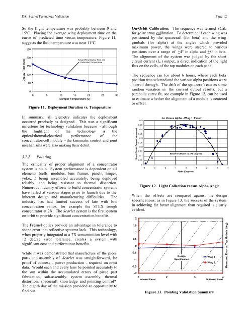
So the flight temperature was probably between 0 and<br />
15ºC. Placing the average wing deployment time on the<br />
curve of predicted time versus temperature, Figure 11,<br />
suggests the fluid temperature was near 11°C.<br />
Deploy Time (sec)<br />
250<br />
200<br />
150<br />
100<br />
50<br />
0<br />
Actual Wing Deploy Time and<br />
Estimated Temperature<br />
0 5 10 15 20 25 30<br />
Damper Temperature (C)<br />
Figure 11. Deployment Duration vs. Temperature<br />
In summary, all telemetry indicates the deployment<br />
occurred precisely as designed. This was a significant<br />
milestone for technology validation because - although<br />
the highlight of the technology is the<br />
optical/thermal/electrical performance of the<br />
concentrator/cell module - the kinematic control and joint<br />
mechanisms were also making their debut.<br />
3.7.2 Pointing<br />
<strong>The</strong> criticality of proper alignment of a concentrator<br />
system is plain. System performance is dependent on all<br />
elements (cells, modules, lens frames, panels, hinges,<br />
yoke,…) being assembled accurately, being deployed<br />
reliably, and being resistant to thermal dis tortion.<br />
Numerous industry efforts to build concentrator systems<br />
have failed at various stages prior to launch due to the<br />
inherent design and manufacturing difficulties. <strong>The</strong><br />
industry has had limited success of late with low<br />
concentration ratios, for example the STEX trough<br />
concentrator at 2X. <strong>The</strong> <strong>Scarlet</strong> system is the first system<br />
on-orbit to provide significant concentration benefits.<br />
<strong>The</strong> Fresnel optics provide an advantage in tolerance to<br />
shape error that reflective systems lack. This technology,<br />
when properly integrated at a 7X concentration level with<br />
+2 degree error tolerance, creates a system with<br />
significant cost and performance benefits.<br />
While it was demonstrated that manufacture of the piece<br />
parts and assembly of <strong>Scarlet</strong> was straightforward, the<br />
proof of success - power production - required on orbit<br />
data. Would each and every lens be pointed accurately to<br />
the sun within the accumulated errors of piece part<br />
fabrication, sub-assembly, system assembly, thermal<br />
distortion, spacecraft knowledge and pointing control<br />
<strong>The</strong> eighth day of the mission provided an opportunity to<br />
find out.<br />
On-Orbit Calibration: <strong>The</strong> sequence was termed SCal,<br />
for solar array calibration. To determine if each wing was<br />
positioned by the spacecraft (for beta) and the wing<br />
gimbals (for alpha) at the angles which provided<br />
maximum power, the wings were steered to various<br />
positions over a range of +4° in alpha and +8° in beta.<br />
<strong>The</strong> alignment of the system was judged by the short<br />
circuit current (I sc ) output, a direct indication of the light<br />
flux on the cells, of the tap modules on each panel.<br />
<strong>The</strong> sequence ran for about 6 hours, where each beta<br />
position was selected and the various alpha positions were<br />
steered through. <strong>The</strong> drift of the spacecraft causes some<br />
random variation in the current output results, but a<br />
parabolic curve fit, see example in Figure 12, can be used<br />
to estimate whether the alignment of a module is centered<br />
or offset.<br />
Short Circuit Current (Amperes)<br />
0.5<br />
0.45<br />
0.4<br />
0.35<br />
0.3<br />
0.25<br />
0.2<br />
0.15<br />
0.1<br />
0.05<br />
Isc Versus Alpha - Wing 1, Panel 1<br />
Best Fit Offset = -0.175 Degrees<br />
0<br />
-4 -3 -2 -1 0 1 2 3 4<br />
Alpha (Degrees)<br />
Figure 12. Light Collection versus Alpha Angle<br />
When the offsets are compared against the design<br />
specifications, as in Figure 13, the success of the system<br />
in achieving far better alignment than required is clearly<br />
evident.<br />
2<br />
1.5<br />
1<br />
0.5<br />
0<br />
-0.5<br />
-1<br />
-1.5<br />
-2<br />
Design<br />
Specification<br />
Wing 1<br />
Wing 2<br />
1 2 3 4<br />
Inboard Panel<br />
Outboard Panel<br />
Figure 13. Pointing Validation Summary<br />
Measured Error at Tap Module (deg)