The Scarlet Solar Array - PDS Small Bodies Node
The Scarlet Solar Array - PDS Small Bodies Node
The Scarlet Solar Array - PDS Small Bodies Node
- No tags were found...

Create successful ePaper yourself
Turn your PDF publications into a flip-book with our unique Google optimized e-Paper software.
DS1 <strong>Scarlet</strong> Technology Validation Page 14<br />
90<br />
RTD Location: Front, Near Cells<br />
90<br />
RTD Location: Front, Between Modules<br />
85<br />
85<br />
80<br />
80<br />
RTD Temperature (C)<br />
75<br />
70<br />
65<br />
60<br />
55<br />
50<br />
45<br />
Wing 1, Panel 1<br />
Wing 1, Panel 4<br />
Wing 2, Panel 1<br />
Wing 2, Panel 4<br />
Analysis<br />
RTD Temperature (C)<br />
75<br />
70<br />
65<br />
60<br />
55<br />
50<br />
45<br />
Wing 1, Panel 1<br />
Wing 1, Panel 4<br />
Analysis<br />
40<br />
0% 20% 40% 60% 80% 100%<br />
% of Full Power Draw<br />
40<br />
0% 20% 40% 60% 80% 100%<br />
% of Full Power Draw<br />
RTD Temperature (C)<br />
90<br />
85<br />
80<br />
75<br />
70<br />
65<br />
60<br />
55<br />
50<br />
45<br />
40<br />
RTD Location: Rear, Behind Cells<br />
Wing 1, Panel 1<br />
Wing 1, Panel 4<br />
Analysis<br />
0% 20% 40% 60% 80% 100%<br />
% of Full Power Draw<br />
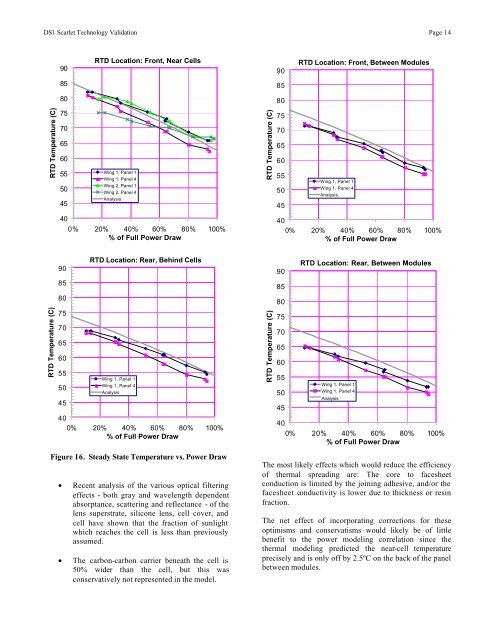
Figure 16. Steady State Temperature vs. Power Draw<br />
• Recent analysis of the various optical filtering<br />
effects - both gray and wavelength dependent<br />
absorptance, scattering and reflectance - of the<br />
lens superstrate, silicone lens, cell cover, and<br />
cell have shown that the fraction of sunlight<br />
which reaches the cell is less than previously<br />
assumed.<br />
• <strong>The</strong> carbon-carbon carrier beneath the cell is<br />
50% wider than the cell, but this was<br />
conservatively not represented in the model.<br />
RTD Temperature (C)<br />
90<br />
85<br />
80<br />
75<br />
70<br />
65<br />
60<br />
55<br />
50<br />
45<br />
40<br />
RTD Location: Rear, Between Modules<br />
Wing 1, Panel 1<br />
Wing 1, Panel 4<br />
Analysis<br />
0% 20% 40% 60% 80% 100%<br />
% of Full Power Draw<br />
<strong>The</strong> most likely effects which would reduce the efficiency<br />
of thermal spreading are: <strong>The</strong> core to facesheet<br />
conduction is limited by the joining adhesive, and/or the<br />
facesheet conductivity is lower due to thickness or resin<br />
fraction.<br />
<strong>The</strong> net effect of incorporating corrections for these<br />
optimisms and conservatisms would likely be of little<br />
benefit to the power modeling correlation since the<br />
thermal modeling predicted the near-cell temperature<br />
precisely and is only off by 2.5ºC on the back of the panel<br />
between modules.