HH, PHH, RHH and CHH HORIZONTAL HYDRONIC FAN ... - First Co.
HH, PHH, RHH and CHH HORIZONTAL HYDRONIC FAN ... - First Co.
HH, PHH, RHH and CHH HORIZONTAL HYDRONIC FAN ... - First Co.
- No tags were found...

Create successful ePaper yourself
Turn your PDF publications into a flip-book with our unique Google optimized e-Paper software.
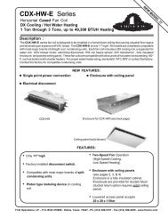
<strong>HH</strong>, P<strong>HH</strong>, R<strong>HH</strong> <strong>and</strong> C<strong>HH</strong><br />
<strong>HORIZONTAL</strong> <strong>HYDRONIC</strong> <strong>FAN</strong> COIL UNITS<br />
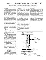
INSTALLATION, OPERATION & MAINTENANCE INSTRUCTIONS<br />
***** WARNING TO INSTALLER, SERVICE PERSONNEL AND OWNER *****<br />
Altering the product or replacing parts with non authorized factory parts voids all warranty or<br />
implied warranty <strong>and</strong> may result in adverse operational performance <strong>and</strong>/or a possible hazardous<br />
safety condition to service personnel <strong>and</strong> occupants. <strong>Co</strong>mpany employees <strong>and</strong>/or contractors are<br />
not authorized to waive this warning.<br />
GENERAL<br />
The manufacturer assumes no responsibility<br />
for equipment installed in<br />
violation of any code requirement.<br />
These instructions give information<br />
relative to the installation of these fan<br />
coil units only. For other related<br />
equipment refer to the proper instructions.<br />
Material in this shipment has been<br />
inspected at the factory <strong>and</strong> released<br />
to the transportation agency in good<br />
condition. When received, a visual<br />
inspection of all cartons should be<br />
made immediately. Any evidence of<br />
rough h<strong>and</strong>ling or apparent damage<br />
should be noted on the delivery receipt<br />
<strong>and</strong> the material inspected in the<br />
presence of the carrier's representative.<br />
If damage is found, a claim<br />
should be filed against the carrier immediately.<br />
****** WARNING ******<br />
Unit must not be operated during<br />
building construction due<br />
to excessive airborne dust <strong>and</strong><br />
debris. The units must not be<br />
operated under any circumstances<br />
without an air filter in<br />
place.<br />
<strong>FAN</strong> COIL UNIT<br />
The installer must adhere strictly to<br />
all local <strong>and</strong> national code requirements<br />
pertaining to the installation of<br />
this equipment. The <strong>HH</strong>, P<strong>HH</strong>, <strong>and</strong><br />
R<strong>HH</strong> units are designed for installation<br />
in a horizontal position above a<br />
dropped ceiling. The C<strong>HH</strong> is a cabinet<br />
unit intended for horizontal exposed<br />
surface mounting.<br />
In a <strong>HH</strong> free return installation (nonducted<br />
return air), the furred down area<br />
must be completely sealed (except<br />
return air grille) to ensure that all return<br />
air is pulled from the conditioned<br />
space <strong>and</strong> not from other areas of the<br />
building structure.<br />
Access must be provided for servicing<br />
the unit. If this access is provided<br />
by a removable ceiling panel, ample<br />
space must be allowed for removal of<br />
the blower panel <strong>and</strong> to provide access<br />
to electrical <strong>and</strong> plumbing controls.<br />
While most fan coil units are U.L.<br />
Listed for installations with zero clearance<br />
to combustible materials, reference<br />
should be made to the marking<br />
on the particular unit being installed<br />
where specific information regarding<br />
clearances is provided.<br />
AIR DISTRIBUTION<br />
DUCTS<br />
All duct work must be installed in<br />
accordance with National Fire Protection<br />
Association <strong>Co</strong>des 90A <strong>and</strong> 90B.<br />
Ducts should be adequately insulated<br />
to prevent condensation during the<br />
cooling cycle <strong>and</strong> to minimize heat<br />
loss during the heating cycle. All<br />
return air must be filtered to prevent<br />
dirt buildup on the coil surface. If there<br />
is no ducted return, applicable installation<br />
codes may limit the unit to installation<br />
only in a single story residence.<br />
In many cases it is acceptable<br />
to use ducting of the same size as the<br />
fan coil connections. However,<br />
unique arrangements or long duct<br />
runs must be confirmed by a local<br />
professional. The manufacturer will<br />
not be responsible for misapplied<br />
equipment.<br />
ELECTRICAL<br />
All wiring must comply with local<br />
<strong>and</strong> national code requirements.<br />
Units are provided with wiring diagrams<br />
<strong>and</strong> nameplate data to provide<br />
information required for necessary<br />
field wiring. On some unit models<br />
remote control boxes are furnished for<br />
field installation. In these instances<br />
care should be taken to assure that the<br />
control box used is the same as that<br />
indicated by the marking on the unit.<br />
The control box should be located as<br />
near the unit as possible in a location<br />
readily accessible for servicing. Wiring<br />
between the control box <strong>and</strong> the<br />
unit must be in accordance with the<br />
****** WARNING ******<br />
Any devices such as fan<br />
switches or thermostats that<br />
have been furnished by the<br />
factory for field installation<br />
must be wired in strict accordance<br />
with the wiring diagram<br />
that is supplied with the unit.<br />
Failure to do so could result<br />
in damage to components <strong>and</strong><br />
will void all warranties.<br />
L2391 9/01
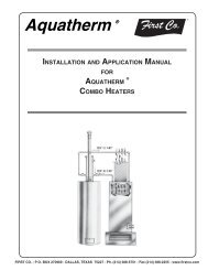
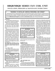
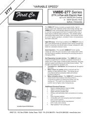
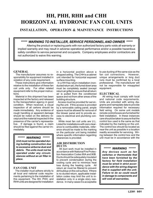
AIR<br />
FLOW<br />
Supply <strong>Co</strong>nnection<br />
Return <strong>Co</strong>nnection<br />
Left H<strong>and</strong> Arrangement<br />
Plenum<br />
(Optional)<br />
Right H<strong>and</strong> Arrangement<br />
Figure 1 - Determination of Right-h<strong>and</strong>/Left-h<strong>and</strong> References<br />
diagrams provided. The field wiring<br />
between the control box <strong>and</strong> the motor<br />
junction box must be installed using<br />
either flexible metal conduit or armored<br />
cable with sufficient length to<br />
allow removal of the blower section for<br />
service access to the heater elements<br />
<strong>and</strong> thermal cutoffs.<br />
These units are provided with a optional<br />
Class 2 transformer for 24-volt<br />
control circuits. Should any add-on<br />
equipment also have a Class 2 transformer<br />
furnished, care must be taken<br />
to prevent interconnecting outputs of<br />
the two transformers by using a<br />
thermostat with isolating contacts.<br />
****** WARNING ******<br />
When connecting piping or<br />
valve kits to fan coil units, do<br />
not bend or reposition the coil<br />
header tubing for alignment<br />
purposes. This could cause a<br />
tubing fracture resulting in a<br />
water leak when water pressure<br />
is applied to the system.<br />
PIPING<br />
These units employ a hydronic coil<br />
designed for use with either hot or<br />
chilled water.<br />
All piping must be adequately<br />
sized to meet the design water flow<br />
requirements as specified for the specific<br />
installation. Piping must be installed<br />
in accordance with all applicable<br />
codes.<br />
The piping connections on the equipment<br />
are not necessarily indicative of<br />
the proper supply <strong>and</strong> return line<br />
sizes. To minimize restrictions piping<br />
design should be kept as simple as<br />
possible.<br />
Caution: Prior to connecting to the<br />
fan coil all external piping must be<br />
purged of debris.<br />
All chilled water piping must be<br />
insulated to prevent condensation.<br />
<strong>Co</strong>ndensate drain lines must be installed<br />
with adequate slope away from<br />
the unit to assure positive drainage.<br />
Since the drain pan is located on the<br />
suction side of the blower, a negative<br />
pressure exists at the drain pan. R<strong>HH</strong><br />
<strong>and</strong> C<strong>HH</strong> fan coil units require a minimum<br />
trap of 1-1/2 inches be provided<br />
in the drain line to assure proper drainage.<br />
<strong>HH</strong> <strong>and</strong> P<strong>HH</strong> fan coil units may<br />
be located where the return air space<br />
is large enough that a negative pressure<br />
is not present, however, a trapped<br />
condensate line is recommended in<br />
case a negative condition should occur,<br />
the unit would drain properly.<br />
PIPING PRECAUTIONS<br />
1. Flush all field piping prior to connection<br />
to remove all debris.<br />
2. Use wet cotton rags to cool valve<br />
bodies when soldering.<br />
3. Open all valves (mid-way for h<strong>and</strong><br />
valves, manually open on motorized<br />
valves) prior to soldering.<br />
4. When soldering to bronze or brass,<br />
heat the piping while in the socket/cup<br />
<strong>and</strong> begin introducing the solder when<br />
the flux boils rapidly.<br />
Avoid direct flame into the solder joint.<br />
5. Heat can only be applied to the cup<br />
of the valve body for a minimal time<br />
before damage occurs (even with the<br />
use of wet rags.<br />
6. Avoid rapid quenching of solder<br />
joints as this will produce joints of<br />
inferior quality.<br />
7. The valve package will not support<br />
the weight of the connecting pipes. All<br />
pipes which are connected to the units<br />
must be completely supported prior to<br />
connection to the unit.<br />
8. Provisions must be made for expansion<br />
<strong>and</strong> contraction of piping systems.<br />
All horizontal <strong>and</strong> vertical risers,<br />
including runouts, must be able to<br />
withst<strong>and</strong> significant movement with<br />
temperature changes. Failure to do<br />
so will result in damage <strong>and</strong> failure of<br />
piping, fittings <strong>and</strong> valves throughout<br />
the building.<br />
9. Never insulate the heads or motorized<br />
portion of control valves. Damage<br />
can occur in the form of excessive heat<br />
build up <strong>and</strong> interference to the operation<br />
<strong>and</strong> moving parts will result.<br />
10. All piping made in the field should<br />
be installed with consideration of additional<br />
space for any electrical routing<br />
that may be required.
11. <strong>Co</strong>nnect all piping per accepted<br />
industry st<strong>and</strong>ards <strong>and</strong> observe all<br />
regulations governing installation of<br />
piping systems. When all connections<br />
are complete the system must<br />
be pressure tested. Repair any solder<br />
joint leaks <strong>and</strong> gently tighten any leaking<br />
valve packing nuts <strong>and</strong> piping accessories<br />
as required. Hydronic systems<br />
are not designed to hold pressurized<br />
air <strong>and</strong> should only be tested<br />
with water.<br />
PIPING INSULATION<br />
After the system has been proven<br />
leak free, all lines <strong>and</strong> valve control<br />
packages must be insulated to prevent<br />
condensate drippage or insulated as<br />
specified on the building plans.<br />
Note: Many valve packages will not<br />
physically allow all components to fit<br />
over an auxiliary drain pan. It is the<br />
installers responsibility to insulate all<br />
piping to ensure adequate condensation<br />
prevention.<br />
DUCT WORK<br />
All duct work must be installed in<br />
accordance with industry accepted<br />
practices, <strong>and</strong> all applicable national<br />
<strong>and</strong> local code requirements.<br />
NOISE<br />
These fan coil units are designed for<br />
quiet operation, however, all air conditioning<br />
equipment will transfer some<br />
amount of noise to the conditioned<br />
space. This should be taken into<br />
consideration when planning the location<br />
of the equipment.<br />
MOUNTING<br />
It is important to ensure that the fan<br />
coils are securely mounted <strong>and</strong> the<br />
structure is sufficient to support the<br />
weight of the equipment. All anchors<br />
for mounting the equipment must be<br />
placed <strong>and</strong> sized to ensure a safe <strong>and</strong><br />
durable installation.<br />
These units are provided with six (6)<br />
mounting holes. Metal washers <strong>and</strong><br />
nuts of the proper size are to be provided<br />
by the installer. When necessary<br />
use shims to obtain the proper<br />
level. This will ensure that the condensate<br />
will drain from the unit.<br />
INSTALLATION<br />
PRECAUTIONS<br />
Installation of this equipment<br />
should only be performed by properly<br />
trained personnel to ensure proper<br />
installation <strong>and</strong> the safety of the installer.<br />
The following are some precautions<br />
to be followed for typical installations.<br />
1. Always use proper tools <strong>and</strong> equipment.<br />
2. No wiring or other work should be<br />
attempted without first ensuring that<br />
the fan coil is completely disconnected<br />
from the power source <strong>and</strong><br />
locked out. Always verify that a good<br />
ground connection exists prior to energizing<br />
any power sources.<br />
3. Always review the nameplate on<br />
each unit for proper voltage <strong>and</strong> control<br />
configurations. This information is<br />
determined from the components <strong>and</strong><br />
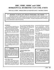
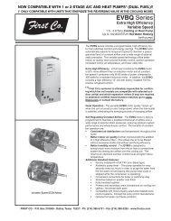
2-Way Motorized Valve Assemblies<br />
1. The motorized valve assembly should be attached to<br />
the supply header which is the connection nearest the air<br />
outlet flange on the unit.<br />
2. Prior to soldering the joints, operate all the h<strong>and</strong> valves<br />
to ensure that the h<strong>and</strong>les will fully open <strong>and</strong> close without<br />
interference to other valves, ceiling, wall, plenum or other<br />
accessories.<br />
3. All valves will operate at any angle with the exception<br />
of the motorized valve, which must never be installed with<br />
the power head below horizontal. The actuator box<br />
requires a 3/4" clearance for removal.<br />
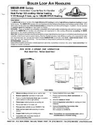
Figure 2 - Installation of Valve Cluster Assemblies<br />
3-Way Motorized Valve Assembly<br />
1. The 3-way valve assemblies will mount to the coil in<br />
only one position.<br />
2. Prior to soldering the joints, operate all the h<strong>and</strong><br />
valves to ensure that the h<strong>and</strong>les will fully open <strong>and</strong><br />
close without interference to other valves, ceiling, wall,<br />
plenum or other accessories.<br />
3. All valves will operate at any angle with the exception<br />
of the motorized valve, which must never be installed with<br />
the power head below horizontal. The actuator box<br />
requires a 3/4" clearance for removal.
wiring of the unit <strong>and</strong> may vary from unit<br />
to unit.<br />
4. When soldering or brazing to the<br />
unit it is recommended to have a fire<br />
extinguisher readily available. When<br />
soldering close to valve packages or<br />
other components heat shields or wet<br />
rags are required to prevent damage.<br />
5. When the fan coil unit is in operation<br />
components are rotating at high<br />
speeds.<br />
****** WARNING ******<br />
Do not touch any rotating<br />
component with any object.<br />
Damage to the equipment <strong>and</strong><br />
personal injury can occur.<br />
6. Units must be installed level to<br />
ensure proper drainage <strong>and</strong> operation.<br />
7. Check unit prior to operation to<br />
ensure that the condensate water will<br />
drain toward the drain connection. An<br />
overflow drain may be required as a<br />
back up to a clogged primary drain.<br />
8. Be sure that the drain pan is free<br />
from foreign material prior to start up.<br />
9. Check filter media installation to<br />
ensure that it is installed correctly.<br />
Use the directional arrows or other<br />
information on the filter to determine<br />
the proper flow direction.<br />
10. Ensure that the air distribution<br />
system does not exceed the external<br />
static rating of the unit.<br />
OPERATION AND<br />
MAINTENANCE<br />
Pre-start Check<br />
1. Check that supply voltage matches<br />
nameplate data.<br />
2. Ensure that the unit is properly<br />
grounded.<br />
3. With power off, check blower<br />
wheel set screws for tightness <strong>and</strong><br />
ensure that the blower wheel(s) rotate<br />
freely <strong>and</strong> quietly.<br />
4. Check that coil(s), valves <strong>and</strong> piping<br />
have been leak checked <strong>and</strong> insulated<br />
as required.<br />
5. Ensure that all air has been vented<br />
from the system.<br />
6. Install all panels.<br />
7. Install any filters which may have<br />
been removed during the installation<br />
process.<br />
****** WARNING ******<br />
• Always wear eye protection.<br />
• When fan coil is operating,<br />
some components are operating<br />
at high speeds. Personal injury<br />
can result from touching these<br />
items with any object<br />
• All electrical <strong>and</strong> service<br />
access panels must be returned<br />
<strong>and</strong> secured in their proper place.<br />
• Clear surrounding area of all<br />
tools, equipment <strong>and</strong> debris.<br />
• Check the entire unit to ensure<br />
it's cleanliness.<br />
Inspection <strong>and</strong> Cleaning<br />
Before start-up all of the components<br />
should be given a thorough<br />
check. Optimal operation of this<br />
equipment requires cleanliness. Often<br />
after installation of this equipment<br />
additional construction activities occur.<br />
Care must be taken to protect the<br />
equipment from debris during these<br />
construction phases.<br />
****** WARNING ******<br />
The manufacturer does NOT<br />
WARRANT equipment subjected<br />
to abuse. Metal chips,<br />
dust, drywall tape, paint over<br />
spray, etc. can void warranties<br />
<strong>and</strong> liability for equipment failure,<br />
personal injury <strong>and</strong> property<br />
damage.<br />
Fan<br />
The fan should be inspected <strong>and</strong><br />
cleaned, in conjunction with maintenance<br />
of the motor <strong>and</strong> bearings. It is<br />
important to keep the wheel clean in<br />
order to avoid imbalance <strong>and</strong> vibration.<br />
Motor<br />
Check motor connections to ensure<br />
that they are secure <strong>and</strong> made in<br />
accordance with the wiring diagram.<br />
The blower motor should be<br />
cleaned annually.<br />
<strong>Co</strong>il<br />
Any dust or other contaminants<br />
which accumulate on the heat transfer<br />
surfaces interferes with the air flow<br />
<strong>and</strong> impairs heat transfer. The coil<br />
must be kept clean by any of the<br />
following methods.<br />
1. Cleaning with low pressure compressed<br />
air.<br />
2. Flushing or rinsing with water (a<br />
detergent is advisable for greasy surfaces).<br />
3. Prior to the water system start-up<br />
<strong>and</strong> balancing, the chilled/hot water<br />
systems should be flushed to clean<br />
out dirt <strong>and</strong> debris which may have<br />
accumulated during construction. All<br />
unit service valves are to closed during<br />
this process. Strainers are to be<br />
installed in the piping mains to prevent<br />
this material from entering the units<br />
during normal operation.<br />
Caution: Be sure to return valves to<br />
their proper operating positions prior<br />
to start-up.<br />
Filter<br />
The air filter should be cleaned or<br />
replaced as often as necessary to<br />
prevent restriction of air flow. Always<br />
replace the filter with the same type as<br />
originally furnished.<br />
Drain Piping<br />
The drain should always be:<br />
-<strong>Co</strong>nnected or piped to an acceptable<br />
disposal point sloped away<br />
from the unit at least 1/8" per foot<br />
-Checked before summer operation<br />
-Periodically checked during summer<br />
operation<br />
Note: A trap may be required per local<br />
codes <strong>and</strong> for odor containment.<br />
Preventative Maintenance<br />
To achieve maximum performance<br />
<strong>and</strong> service life of each piece of equipment<br />
a formal schedule of regular<br />
maintenance should be established<br />
<strong>and</strong> maintained.