O:\L2465 UC-HW Inst\L2465 4-05 - First Co.
O:\L2465 UC-HW Inst\L2465 4-05 - First Co.
O:\L2465 UC-HW Inst\L2465 4-05 - First Co.

You also want an ePaper? Increase the reach of your titles
YUMPU automatically turns print PDFs into web optimized ePapers that Google loves.
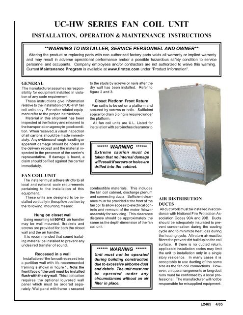
<strong>UC</strong>-<strong>HW</strong> SERIES FAN COIL UNITINSTALLATION, OPERATION & MAINTENANCE INSTR<strong>UC</strong>TIONS**WARNING TO INSTALLER, SERVICE PERSONNEL AND OWNER**Altering the product or replacing parts with non authorized factory parts voids all warranty or implied warrantyand may result in adverse operational performance and/or a possible hazardous safety condition to servicepersonnel and occupants. <strong>Co</strong>mpany employees and/or contractors are not authorized to waive this warning.Current Maintenance Program is available at www.firstco.com under "Product Information".GENERALThe manufacturer assumes no responsibilityfor equipment installed in violationof any code requirement.These instructions give informationrelative to the installation of <strong>UC</strong>-<strong>HW</strong> fancoil units only. For other related equipmentrefer to the proper instructions.Material in this shipment has beeninspected at the factory and released tothe transportation agency in good condition.When received, a visual inspectionof all cartons should be made immediately.Any evidence of rough handling orapparent damage should be noted onthe delivery receipt and the material inspectedin the presence of the carrier'srepresentative. If damage is found, aclaim should be filed against the carrierimmediately.FAN COIL UNITThe installer must adhere strictly to alllocal and national code requirementspertaining to the installation of thisequipment.These units are designed to be installedvertically in the upflow position bythe following mounting means:Hung on closet wallUsing mounting kit 90PK3, air handlermay be wall mounted. Brackets andscrews are provided for both the closetwall and the air handler.It is recommended that sound isolatingmaterial be installed to prevent anyundesired transfer of sound.Recessed in a wallInstallation of the fan coil recessed intoa partition wall with it's recommendedframing is shown in figure 1. Note: thefront face of the unit must be installedflush with the dry wall. This applicationrequires the optional louvered wallpanel which must be ordered separately.Wall panel with frame is securedto the studs by screws or nails after thedry wall has been installed. Refer tofigure 2 and 3.Closet Platform Front ReturnFan coil is to be set on a platform andsecured by screws or nails. Sufficientspace for drain piping is required underthe platform.All fan coil units are U.L. Listed forinstallation with zero inches clearance to****** WARNING ******Extreme caution must betaken that no internal damagewill result if screws or holes aredrilled into the cabinet.combustible materials. This includesthe fan coil cabinet, discharge plenumand connecting ducts. Sufficient clearancemust be provided at the front of thefan coil to allow access to electrical controlsand removal of the motor /blowerassembly for servicing. This clearancedistance should be approximately thesame as the depth dimension of the fancoil unit.****** WARNING ******Unit must not be operatedduring building constructiondue to excessive airborne dustand debris. The unit must notbe operated under anycircumstances without an airfilter in place.AIR DISTRIBUTIOND<strong>UC</strong>TSAll duct work must be installed in accordancewith National Fire Protection Association<strong>Co</strong>des 90A and 90B. Ductsshould be adequately insulated to preventcondensation during the coolingcycle and to minimize heat loss duringthe heating cycle. All return air must befiltered to prevent dirt buildup on the coilsurface. If there is no ducted return,applicable installation codes may limitthe unit to installation only in a singlestory residence. In many cases it isacceptable to use ducting of the samesize as the fan coil connections. However,unique arrangements or long ductruns must be confirmed by a local professional.The manufacturer will not beresponsible for misapplied equipment.L2465 4/<strong>05</strong>
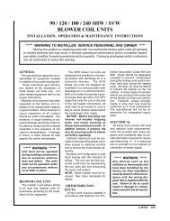
ELECTRICALAll wiring must comply with local andnational code requirements. Units areprovided with wiring diagrams andnameplate data to provide informationrequired for necessary field wiring. Referto figure 2 for points of entry of thewiring into the cabinet.****** WARNING ******Any devices such as fanswitches or thermostats thathave been furnished by the factoryfor field installation mustbe wired in strict accordancewith the wiring diagram that issupplied with the unit. Failureto do so could result indamage to components andwill void all warranties.These units may be provided with aClass 2 transformer for 24-volt controlcircuits. Should any add-on equipmentalso have a Class 2 transformer furnished,care must be taken to preventinterconnecting outputs of the two transformersby using a thermostat with isolatingcontacts.INSTALLATIONPRECAUTIONSInstallation of this fan coil should onlybe performed by a licensed contractor toensure proper installation and the safetyof the installer. The following are someprecautions to be followed for typicalinstallations.• Always use proper tools and equipment.• No wiring or other work should beattempted without first ensuring that thefan coil is completely disconnected fromthe power source and locked out. Alwaysverify that a good ground connection existsprior to energizing any powersources.• Always review the nameplate on eachunit for proper voltage and control configurations.This information is determinedfrom the components and wiringof the unit and may vary from unit to unit.• When soldering or brazing to the unit,it is recommended to have a fire extinguisherreadily available. When solderingclose to valve packages or othercomponents, heat shields or wet ragsare required to prevent damage.• When the fan coil unit is in operationcomponents are rotating at highspeeds.• Units must be installed level to ensureproper drainage and operation.• Check unit prior to operation to ensurethat the condensate water will drain towardthe drain connection. An overflowdrain or an auxiliary drain pan under thefan coil may be required as a back up toa clogged primary drain.• On units with plastic drain pans DONOT tighten more than hand tight.• Be sure that the drain pan is free fromforeign material prior to start up.• Check filter media installation to ensurethat it is installed correctly. Use thedirectional arrows or other informationon the filter to determine the proper flowdirection.NOISEThese fan coil units are designed forquiet operation, however, all air conditioningequipment will transfer someamount of noise to the conditionedspace. This should be taken into considerationwhen planning the location of theequipment.COOLING COIL PIPINGThese fan coil units are supplied with adirect expansion refrigerant coil. Thesuction and liquid lines must be sized inaccordance with the outdoor unitmanufacturer's recommendations.<strong>Co</strong>ndensate drain lines must be installedwith adequate slope away fromthe unit to assure positive drainage.Since the drain pan is located on thesuction side of the blower, a negativepressure exists at the drain pan and aminimum trap of 1-1/2 inches must beprovided in the drain line to assureproper drainage.NOTE: If a <strong>Co</strong>ndensate Overflow ShutoffSwitch, that is designed to be installedin the drain line, is used in place of asecondary drain line, then the cut-offswitch should be located in the primarydrain line between the fan coil unit andthe P-trap.<strong>UC</strong>-<strong>HW</strong> RECESSED WALL MOUNTINGCROSS MEMBER - TOP & BOTTOM(PLACE UPPER CROSS MEMBER 3"ABOVE <strong>UC</strong> UNIT)ATTACH UNIT TO FRAME USING 6SCREWS / NAILS IN CABINET ATLOCATIONS SHOWN****** WARNING ******On units with plastic drainpans the drain connectionsmust be made hand tight only.VERTICAL 2 X 4WALL STUDSBRACKET PLACEMENT FORHANGING IN A CLOSETMOUNT UNIT FLUS<strong>HW</strong>ITH DRY WALL(1/2" MIN. IN FRONTOF WALL STUD)****** WARNING ******Do not touch any rotatingcomponent with any object.Damage to the equipment andpersonal injury can occur.SUPPORT FRAMINGFigure 1LEAVE SUFFICIENTSPACE FOR DRAINPIPING10" TO 12" MINIMUMRECOMMENDED
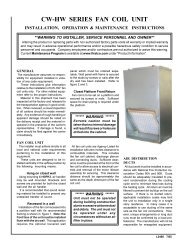
HOT WATER COILPIPING PRECAUTIONS• Flush all field piping prior to connectionto remove all debris.• Use wet cotton rags to cool valve bodieswhen soldering.• Open all valves (midway for handvalves, manually open on motorizedvalves) prior to soldering.•When soldering to bronze or brass, heatthe piping while in the socket/cup andbegin introducing the solder when theflux boils rapidly. Avoid direct flame intothe solder joint.• Heat can only be applied to the cup of thevalve body for a minimal time beforedamage occurs (even with the use of wetrags.• Avoid rapid quenching of solder jointsas this will produce joints of inferior quality.****** WARNING ******When connecting piping tofan coil units, do not bend orreposition the coil header tubingfor alignment purposes.This could cause a tubing fractureresulting in a water leakwhen water pressure is appliedto the system.• <strong>Co</strong>nnect all piping per accepted industrystandards and observe all regulationsgoverning installation of pipingsystems. When all connections arecomplete the system must be pressuretested. Repair any solder joint leaks andgently tighten any leaking valve packingnuts and piping accessories as required.Hydronic systems are not designedto hold pressurized air andshould only be tested with water.HOT WATER COIL PIPINGRefer to Flow <strong>Co</strong>ntrol Module installationinstructions for proper pump installation,if used.The hot water coil connections are 3/4 inch nominal (7/8” OD) copper. The hotwater supply to the fan coil should be onthe right when facing the fan coil uprightand from the front.****** WARNING ******An expansion tank may be requiredif a back-flow preventeris installed in the system.All piping between the water heaterand fan coil unit should be copper andshould not exceed 200 feet of total piping.It is recommended that 3/4” nominal(7/8” OD) piping should be used on all<strong>UC</strong>-<strong>HW</strong> units to prevent excessive headpressure losses. (<strong>Co</strong>nsult the factory forother piping applications.)It is also recommended that all pipingbe adequately insulated to preventfreezing when piping is run in an unconditionedspace.Solder <strong>Co</strong>nnections - All copperjoints in the water lines must be madewith low temperature - non leadsolder."T" <strong>Co</strong>nnections (at the waterheater)-Water lines to and from the fan coil unitmust be taken from the horizontal connectionof the "T" fittings in the vertical hotand cold water supply lines at the waterheater. This ensures that any air in thesystem will be purged each time water isused in the dwelling. See figure 4.Isolation Valves - Two valves arerecommended to be installed within thecirculating loop to permit servicingof the system if required and to assist inpurging the system.NOTE: Hot water coil freeze protectionis available for applications where thefan coil is located in ambient air locations(attics, crawl spaces, etc.) or withinstructures that may be unoccupied duringfreezing conditions. <strong>Co</strong>nsult the factoryfor additional information.OPERATION ANDMAINTENANCEPre-start Check• Check that supply voltage matchesnameplate data.• Ensure that the unit is properlygrounded.• With power off, check blower wheelset screw for tightness and ensure thatthe blower wheels rotates freely andquietly.• Check that the refrigerant coil connectionsand piping have been leak checkedand insulated as required.• Check that the water coil, valves andpiping have been leak checked and insulatedas required.• Ensure that all air has been ventedfrom the hot water coil.NOTE: It may require purging severalgallons of water so have a means ofdiscarding the water.• Install all panels.• Install any filters which may havebeen removed during the installationprocess.THERMOSTATWIRINGPOWERSUPPLY WIRINGLIQUID LINES<strong>UC</strong>TION LINE2 x 4 WALL STUD2 X 4WALL STUDDRY WALL<strong>UC</strong> WALL PANEL FRAME(PANEL ASSEMBLY ISORDERED SEPARATELY)WATEROUTLETCROSS MEMBER(ON EDGE)INSTALLED UNITTOP VIEWFigure 2WATERINLETDRY WALLNote: Front edge of unitto be flush with dry wall.SCREWDETAIL OF WALL PANEL FRAMEINSTALLATIONFigure 3WALL PANELFRAME
****** WARNING ******• Always wear eye protection.• When fan coil is operating,some components are operatingat high speeds. Personal injurycan result from touching theseitems with any object• All electrical and serviceaccess panels must be returnedand secured in their proper place.• Clear surrounding area of alltools, equipment and debris.• Check the entire unit to ensureit's cleanliness.Start-up and MaintenanceBefore start-up, all of the componentsshould be given a thorough check. Optimaloperation of this equipment requirescleanliness. Often afterinstalllation of this equipment additionalconstruction activities occur. Care mustbe taken to protect the equipment fromdebris during these constructionphases.FanThe fan should be inspected andcleaned, in conjunction with maintenanceof the motor and bearings. It isimportant to keep the wheel clean inorder to avoid imbalance and vibration.MotorCheck motor connections to ensurethat they are secure and made in accordancewith the wiring diagram.The blower motor should be cleanedannually.<strong>Co</strong>ilAny dust or other contaminants whichaccumulate on the heat transfer surfacesinterferes with the air flow andimpairs heat transfer. The coil must bekept clean by any of the following methods.• Cleaning with low pressure compressedair.• Flushing or rinsing with water (a detergentis advisable for greasy surfaces).FilterThe air filter should be cleaned or replacedevery 30 days or more frequentlyif severe conditions exist. Always replacethe filter with the same type asoriginally furnished.****** WARNING ******The manufacturer does NOTWARRANT equipment subjectedto abuse. Metal chips,dust, drywall tape, paint overspray, etc. can void warrantiesand liability for equipment failure,personal injury and propertydamage.Drain PipingThe drain should always be:• <strong>Co</strong>nnected or piped to an acceptabledisposal point sloped away from theunit at least 1/8" per foot• Checked before summer operation• Periodically checked during summeroperationPreventative MaintenanceTo achieve maximum performanceand service life of each piece of equipmenta formal schedule of regular maintenanceshould be established andmaintained by a licensed contractor.HEATING CYCLESTART - UP1) Fill the water heater. Open a hot waterfaucet while filling the water heater tovent the air. When the tank is full andall the air is purged, close the faucet.2) Ignite the water heater and set thethermostat to 140 degrees.3) Purge the air handler's hot water coiland lines.NOTE: It may require purging severalgallons of water so either have abucket available or a means of discardingthe water.Close valve number 2 and open valvenumber 3. (See figure 4 ) Next, openthe air bleed valve. When all of the airis purged from the lines close valvenumber 3 and open valve number 2.After all the air is purged from the coiland lines, open both valve number 1and 2 and close the air bleed valve.4) Switch the room thermostat to the"Heat" position and raise the temperaturesetting to a position approximatelyten degrees above room temperature.The pump should energize and begincirculating the hot water throughthe coil. If the pump is operating****** WARNING ******To prevent pump damage, thefan coil unit should not beenergized for heating until thehot water coil and all waterlines have been purged of air.properly and the water temperaturein the water heater has reached theset point, then the hot water inlet at thefan coil unit will be hot. If the pump isrunning but hot water is not circulating,open the air bleed valve longenough to purge any remaining airfrom the hot water lines and coil. Thiswill allow the pump to begin circulatinghot water.****** WARNING ******Hot water can cause scalding.A hot water mixing valve canbe applied to the system totemper domestic water draw.5) The water heater thermostat shouldbe adjusted so that the water temperatureentering the hot water coil isas close to 140 degrees as possiblewith the system energized and operatinglong enough for all temperaturesto stabilize.PUMP REPLACEMENT(If Flow <strong>Co</strong>ntrol Module isinstalled)Disconnect electrical power beforeservicing the unit.To replace the circulator pump, closethe isolation valves and relieve the waterpressure within the heating loop. Disconnectthe pump's 115 volt power lineswithin the control box and remove thefour hex head screws securing the pumpmotor to the pump's volute.Reverse the above steps for reassemblingthe pump, however make surethat the pump or volute has the rubber o-ring in place before assembling.CHECK VALVEREPLACEMENTDisconnect electrical power beforeservicing the unit.To replace the internal check valve,close the isolation valves and relieve thewater pressure within the heating loop.Remove the four hex head screws se-
curing the pump motor to the pump'svolute and remove. The check valve islocated in the volute.Rotate the check valve to release andremove from the volute.Reverse the above steps for reinstallinga check valve, however makesure that the pump or volute has therubber o-ring in place before assembling.**MAINTENANCE UPDATES**For a current copy of theMaintenance Program log onto www.firstco.com andlook under "Product Information"TYPICAL PIPING SCHEMATICw / Flow <strong>Co</strong>ntrol ModuleHOT WATERSUPPLY TOHOUSE2FLOW1FLOW CONTROLMODULEFLOWWATER SUPPLYTO HEATER3BLEEDVALVEFLOWHOT WATER COILHOTWATERHEATER1)FLOW CONTROL MODULECONSIST OF: PUMP, CHECKVALVE AND BLEED VALVE2) ISOLATION VALVE: SUPPLY LINE3) ISOLATION VALVE: RETURN LINEFigure 4