
You also want an ePaper? Increase the reach of your titles
YUMPU automatically turns print PDFs into web optimized ePapers that Google loves.
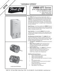
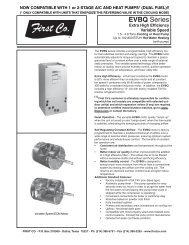
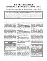
ume sizing guide <strong>is</strong> sat<strong>is</strong>factory in most parts of thecountry: (minimum requirements)1.5 and 2 ton air handlers = minimum 40 gallon2.5 and 3 ton air handlers = minimum 50 gallon3.5 and 4 ton air handlers = either two 40 gallon waterheaters piped together, one high input (63,000 to75,000 BTUH) 50 gallon or one 72 to 75 gallon.5.0 ton air handlers = multiple water heaters or boilerwith at least 105,000 BTUH output.For additional ass<strong>is</strong>tance in water heater sizing,contact the factory or a qualified profession engineer.INSTALLATIONThe installer must adhere strictly to all local andnational code requirements pertaining to the installationof th<strong>is</strong> equipment.Detailed installation instructions are shipped witheach component of the system and should also befollowed in detail.Duct work: The return air duct must have the samefree area as the opening provided on the air handler.If there <strong>is</strong> no ducted return, applicable installationcodes may limit the unit to installation only in a singlestory residence.Electrical: Units are provided with wiring diagramsand nameplate data to provide information requiredfor necessary field wiring. Knockouts are provided inthe cabinet for connection of power supply. See “accessories”for thermostat information. All air handlersoperate on 115 volt - 1phase - 60 cycle line voltageand 24 volt control.5
(See figures 3, 4, 5, 14 and 15 for typical wiringdiagrams.)Water piping:1. Material: It <strong>is</strong> recommended that all piping betweenthe water heater and hot water coil be3/4 inch nominal (7/8 O.D.) copper except the60HBQB and 60HBXB-HW <strong>is</strong> 1" nominal (1-1/8"O.D.). Other material approved for potable hot watersystems may also be used if approved by localcode authorities.2. Solder connections: All copper joints in the waterlines must be made with low temperature, nonlead solder!3. Insulation: It <strong>is</strong> recommended that all pipingbe adequately insulated to prevent freezing and“freeze protector” ( see “accessories” ) be installedon the hot water coil to prevent freezing whenpiping <strong>is</strong> run in a space subjected to freezingtemperatures.4. Length: Piping should not exceed 200 total feet oflength. Air handlers should not be installed morethan 40 feet above the water heater.5. Shut - off valves: In addition to the main coldwater valve supplying the water heater, it <strong>is</strong> recommendedthat one shut - off valve be installedon the hot water supply line to the air handler andone on the return line from the air handler (or hotwater coil). These valves will facilitate air purgingduring start - up ( see “start - up” ) and allow unit<strong>is</strong>olation for repair.6. Piping connections: On all cased type air handlersthe water inlet or “supply” connection to thehot water coil <strong>is</strong> the one on the right as you facethe the air handler and will be marked accordingly.Air handlers with internally installed circulatingpumps will not circulate water if piped backwards.Water lines to and from the air handlermust be connected to the horizontal connectionof the “T” fittings in the vertical hot and cold watersupply lines at the water heater. (See figure 6).Th<strong>is</strong> insures that any air in the water heater willbypass the heating loop and then be purged eachtime hot water <strong>is</strong> used in the dwelling. If th<strong>is</strong> pipingprocedure <strong>is</strong> not followed the pump may “airlock” and fail to pump hot water. Any other pipingprocedure must address the elimination of air inthe heating loop. See figures 8 through 9 for approvedpiping variations. <strong>Co</strong>ntact the factory forass<strong>is</strong>tance with alternate piping procedures.Air handler: Holes should not be drilled into the airhandler or coil cabinets (except through duct flanges)since damage to the coils could result. Multiple airhandlers may be installed on one water heater providedthe water heater and piping are sized properly.Piping should be similar to that required for individualair handler.Flow control module (if required): The flow controlmodule can be installed anywhere in the hot waterloop to or from the air handler (between the waterheater and air handler). Modules must be installedwith the motor in a horizontal position. Junction boxshould not be installed underneath the pump. Watershould flow from the outlet (hot) side of the waterheater to the air handler and then back to the supply(cold ) side of the water heater. Arrow on bottom ofpump indicates the direction of flow when pump <strong>is</strong>energized. The module <strong>is</strong> furn<strong>is</strong>hed with a 6 foot cordand plug for convenient connection to a wall outlet.For those areas where local codes require “hard”wiring, d<strong>is</strong>card the cord assembly and wire directly tothe connections within the 4 x 4 box using acceptablewiring materials.Water heater: Water heaters should be installed accordingto the manufacturer’s installation instructions.If a “back flow preventer” <strong>is</strong> required by code,the T & P valve on the water heater may tend todrip water because of pressure build-up in the water6
heater. Th<strong>is</strong> problem <strong>is</strong> a direct result of the backflow preventer . . . . . not the heating system. Anexpansion tank may need to be installed to solve th<strong>is</strong>problem. Most water heaters are now labeled withth<strong>is</strong> information.Multiple water heaters: When sizing requirementscall for more than one water heater per air handler,water heaters may be connected together accordingto the water heater manufacturer’s instructions. (Seefigure 10 page 9)Anti-scald valve: A water heater <strong>is</strong> designed toproduce hot water. Hot water represents a serioussafety hazard due to the potential of scalding. Thetemperature of water normally required to providespace heating (135 to 140 degrees) may be hotterthan certain codes allow for domestic hot water. An“anti-scald valve” can be installed in the hot waterpiping that would allow the domestic water to be suppliedat a lower temperature than the space heatingwater. These can be obtained locally and should beinstalled according to the manufacturer’s installationinstructions. (See figure 12)START - UP PROCEDURE(Heating cycle)1. Open the main shut - off valve to the water heaterand the two shut - off valves to and from the airhandler or hot water coil.2. Fill the water heater. Open a hot water faucetsomewhere in the house while filling the waterheater in order to vent the air. When the tank <strong>is</strong>full and all the air <strong>is</strong> purged, close the faucet.3. Ignite the water heater according to the manufacturer’sinstructions and allow it to come up totemperature (about 45 minutes). DO NOT IGNITETHE WATER HEATER WITHOUT WATER INTHE TANK!4. Purge the air handler’s hot water coil and lines: Thefollowing procedure allows the use of city waterpressure to purge the air handler hot water coil andlines even when the air handler <strong>is</strong> located higherthan the water heater. Once the air <strong>is</strong> completelyremoved upon start - up, the circulating pumpwill circulate the required amount of hot waterthrough the heating loop.Note: It may require purging several gallons of waterso either have a bucket available or connect a gardenhose to the purge valve and route to a drain.Close valve number 2 and open valve number 3(See figure 7). Next , open the air purge valvelocated either on the flow control module or insidethe air handler. When all the air <strong>is</strong> purged, closevalve number 3 and open valve number 2. Whenall the air <strong>is</strong> purged, open both valves and closethe air purge valve.5. On Grundfos pumps, vent the air from the pumpchamber by loosening the large screw plug ontop of the pump motor until water appears. Thenretighten the plug.6. Switch the room thermostat to “heat” and set it highenough to energize the fan motor and pump. Itmay be necessary to “feel” the pump to determineif it <strong>is</strong> operating. If the pump <strong>is</strong> operating properlyand the water temperature in the water heater hasreached the set point, the hot water line going intothe air handler will begin to get hot. If the pump<strong>is</strong> running but hot water <strong>is</strong> not circulating, refer to"troubleshooting”.7. Adjust the water heater thermostat so that the waterentering the hot water coil <strong>is</strong> 135 to 140 degreeswith the system energized and operating longenough for all temperatures to stabilize.7
<strong>Co</strong>nventional Piping DiagramFIGURE 8Side Tap (4 Pipe) Water Heater PipingFIGURE 98
9FIGURE 10
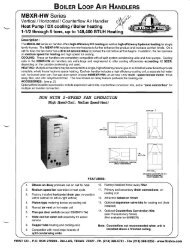
Zone ValvesInstall a motorized valve with each air handler to control flow to that zone asrequired.FIGURE 11TYPICAL WIRING SCHEMATICFOR MULTIPLE ZONE CONNECTIONSWITH ZONE VALVES24 VOLTCLASS 2 WIRING4 CONDUCTORCLASS 2 WIRING24 VOLTCLASS 2 WIRINGGWGWHBXB-HWFAN COILTTTTHBXB-HWFAN COILGWGWRR24V24VRRY24V REMOTETHERMOSTATBRNCPIGTAIL LEADS FORMOTORIZED VALVE24VTT24VPIGTAIL LEADS FORMOTORIZED VALVECBRNY24V REMOTETHERMOSTATCONDENSERCONTACTORNOTE: CAP OFFBROWN IF NOCONDENSING UNITIS USEDMV24V MOTORIZEDZONE VALVEBOILERMV24V MOTORIZEDZONE VALVENOTE: CAP OFFBROWN IF NOCONDENSING UNITIS USEDCONDENSERCONTACTORTYPICAL WIRING SCHEMATICFOR MULTIPLE ZONE CONNECTIONS TOTACO SR-504/506 SWITCHING RELAY24 VOLTCLASS 2 WIRINGCLASS 2 WIRING24 VOLTCLASS 2 WIRINGGWGWHBXB-HWFAN COILTTTTHBXB-HWFAN COILGWGWRR24V24VRRY24V REMOTETHERMOSTATBRNC24VTACOSR 504ZONE 1 ZONE 3ZONE 2 ZONE 424VCBRNY24V REMOTETHERMOSTATCONDENSERCONTACTORNOTE: CAP OFFBROWN IF NOCONDENSING UNITIS USEDBOILERSWITCHINGRELAYTTX X120V CIRCULATORCONNECTIONSNOTE: CAP OFFBROWN IF NOCONDENSING UNITIS USEDCONDENSERCONTACTOR10
Catalog No. IAM1010 (Replaces IAM309)12